1
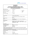
9. Technical Specifications
Power Unit Specification:
Part number:
Input:
Power consumption:
Fuse rating:
Weight:
Dimension:
UK and Euro Electrical Safety Standards:
Complies with:
Degree of protection against electric shock:
Degree of protection against water ingress:
Mode of operation:
Integrity® Specification:
Dimension:
Weight of air mattress within a bag:
Accessories/Spare Parts:
Detachable mattress cover 2-way stretch cover:
Alternating pressure mattress system complete:
Alternating pressure mattress (including tube but not the pump):
Alternating pressure mattress system pump:
Carry bag:
Power lead:
Environmental Protection:
Please dispose of this unit in accordance with local regulations.
Retardancy:
Complies with BS7177 crib 5, BS597-1, BS597-2
12345P
220-240V AC, 50Hz
10W max
T1AL/250V
1.5kg (approx)
L26cm x W8cm x H13cm
EN 60601-1:1990/A13:1996
Class I, Type BF
IPX0
Continuous
L195.5cm x W86.4cm x 15cm (approx)
12kg (approx)
Part No 12345C
Part No 12345
Part No 12345M
Part No 12345P
Part No 12345B
Part No 12345PL
10. Warranty and Service
In the event of a problem you must first contact your supplier. The Manufacturer, Sumed®, recommends
that this product is serviced annually.
This product carries a Manufacturer’s warranty period for the power unit and the air mattress of 2 years
against manufacturing defects. The Manufacturer’s warranty will be invalidated if the tamper-evident
seal on the pump has been broken.
For after sales service, maintenance and any questions regarding this, or any other Sumed® product,
please contact:
Sumed International (UK) Limited
Integrity House, Units 1-2 Graphite Way, Hadfield, Glossop, Derbyshire SK13 1QH
Telephone 01457 890980 Fax 01457 890990
Website: www.sumed.co.uk E-mail: [email protected]
12
User Manual
INTEGRITY® AUTO ADJUSTING FULL DYNAMIC REPLACEMENT MATTRESS SYSTEM
Maximum Working Load Limit 178kg (28 stones)
General Safety
Introduction
Before connecting the pump to a mains socket, carefully read all the installation instructions in
Section 4 Page 8 “Installation and Set Up”
About this manual
Safety Criteria
This product conforms with the requirements of
EN60601, EN60601-1, EN 60601-1-2.
Safety Warnings
The product is only intended to be used as an aid to assist
in healing and prevention of pressure ulcers and should be
used in conjunction with a patient-specific care plan.
The Manufacturer cannot be held responsible for
inappropriate or incorrect use.
• Do not tamper with the power unit.
• The power unit is not suitable for use in anaesthetic
procedures involving inflammable gases.
• Do not pull the CPR tag in normal working use
except in an emergency situation.
For your own safety and the safety of the equipment,
always take the following precautions:
• Apart from thin cover sheets, placing extra layers
between the patient and the system reduces the
benefits provided by the system. The mattress cover
should not be pulled tight and covering sheets
should fit loosely.
• It is advisable to avoid wearing clothing which may
cause areas of localised high pressure due to creases,
seams, or similar risks.
• Keep the pump away from liquids.
• Do not expose the system to naked flames or other
heat sources.
• Do not store the system in direct sunlight.
• Do not use sharp or pointed objects or subject the
mattress to high temperatures.
• Disconnect the pump from the mains power supply
before cleaning before cleaning.
• The cover of this product is vapour permeable but
not air permeable and may present a suffocation
risk. It is the responsibility of the user to ensure that
this product can be used safely.
• Do not use phenol-based solutions to clean the
system.
• Electrical equipment may be hazardous if misused.
The pump should only be dismantled by authorised
technical personnel.
• Do not use the pump in the presence of flammable
gases such as anaesthetic gas or in places exposed to
water, liquids, oil, smoke and flammable chemicals.
• Safety sides/bed rails should be used at an
appropriate height based on clinical assessment and
in line with local hospital policy and/or risk
assessments.
• Ensure that there are no gaps wide enough to entrap
a patient's head or body between the system and
the bed frame. Care should be exercised to prevent
occurrence of gaps by compression or movement of
the system as death or serious injury may occur.
2
Precautions
This manual is your introduction to Integrity® Auto
Adjusting Full Dynamic Replacement Mattress
System. Use this manual to initially set up the
system, and keep it as a reference for day-to-day
routines and as a guide to maintenance.
Noise levels should be less than 30dB.
Contents
1. Usage and Controls of the Integrity® Pump
Page 4 - 5
2. Integrity® Mattress Components
Page 6 - 7
About Integrity®
Integrity® is an Auto Adjusting Full Dynamic
Replacement Mattress System to assist in the
prevention, treatment and management of pressure
ulcers.
3. Clinical Applications
Page 8
Integrity® comprises a pump and mattress
replacement system which can be used on standard
hospital, profiling, auto regression and normal
domestic beds with bed rails or sides. Beds can be
adjusted or profiled with the Integrity® mattress
in position.
4. Installation and Set Up
Page 8
5. Operation
Page 9
6. Cleaning and Decontamination
Page 10
• Make sure the system is clean and dry prior to use or
storage.
7. Routine Maintenance
Page 11
• Never use sharp objects or electrically heated underblankets on or under the system.
• Store the pump and mattress in the protective bag
supplied.
• Only the pump and mattress combination as
supplied by Sumed® should be used. The correct
function of the product cannot be guaranteed if any
other Manufacturer’s pump and mattress
combination is used.
• Maximum working load limit is 178kg (28 stones)
Manufactured by
Sumed International (UK) Ltd
Integrity House, Units 1-2 Graphite Way
Hadfield, Glossop, Derbyshire SK13 1QH
Telephone 01457 890980 Fax 01457 890990
[email protected] www.sumed.co.uk
8. Troubleshooting
Page 11
9. Technical Specifications
Page 12
10. Warranty and Service
Page 12
3
1. Usage and Controls of the Integrity® Pump
The controls and indicators are located on the top panel:
Auto Firm (Nursing): When carers are providing nursing care, the mattress is pressurised to be
flat and firm to provide a more stable surface to make nursing care easier. When the green indicator
is on, the Auto Firm (Nursing) button is activated. However, after 30 minutes, the unit will resume
its previous setting in order to protect the patient from the risk of developing pressure ulcers. This
can be used in Lock or Unlock mode.
Auto Dual Mode: This enables a combination of pressure therapy. The function enables
Alternating and Static Modes to alternate on one hour cycles. The mattress automatically adjusts to
the set comfort level.
• As an example, if the Alternating Comfort setting is 27mmHg, this will adjust to a Static Mode
setting of 18mmHg. If the Alternating Comfort setting is 38mmHg, this will adjust to a Static
Mode setting of 24mmHg. This can only be used in Unlock mode.
The pump can be fixed to the foot-end of a hospital bed by the bed brackets provided. The pump can also be
placed upright on the floor.
Low Pressure Alarm: The alarm automatically sounds when a low air pressure is detected in the
mattress. The alarm can be muted by pressing the Low Pressure Alarm button. In order to restore
the audible alarm function, you have to press the On/Standby button and reset to a chosen setting.
This can only be used in Unlock mode.
On/Standby: When the green indicator is on, this means that the power unit will start to operate.
When the orange indicator is on, this means that the unit is in Standby mode and will not operate.
This can only be used in Unlock mode.
Power Failure Alarm: The alarm automatically sounds within 80 seconds when there is a loss of
power during normal operation of the system.
Comfort: Select the green indicators for a soft, medium or firm setting. The power unit
automatically adjusts and shifts to the most appropriate pressure depending on the selected
setting. This function can be used only to adjust the Comfort level around the preset levels for
S (Soft), M (Medium) and F (Firm).
• The indicators do not turn on during normal operation. However, when the orange indicators are
on, it means that either the Low Pressure Alarm or the Power Failure Alarm has sounded. The
alarm can be muted by pressing the Power Failure Alarm button. If a prolonged power failure
occurs refer to initial set-up.
In Alternating Mode: Soft = 20mmHg, Medium = 30mmHg, and Firm = 40mmHg. The up and
down arrow will allow for adjustment between 20-29 on the S setting, 30-39 on the M setting and
40-49 on the F setting. This adjustment can only be made in Unlock mode.
Lock/Unlock: This is used to prevent the user from accidentally changing the control panel
settings. The button can lock the existing settings status. Press again to unlock.
In Static Mode: Soft = 15mmHg, Medium = 20mmHg, and Firm = 25mmHg. The up and down
arrow will allow for adjustment between 15-19 on the S setting, 20-24 on the M setting and 25-29
on the F setting. This adjustment can only be made in Unlock mode.
Alternating Mode: This feature allows the time cycle to be changed from its default cycle time of
10 minutes per cycle. Options include: 5, 10, 15 or 20 minutes per cycle. The green light indicates
which cycle time has been selected.
• Please note the ON/Standby button will also be locked as an additional safety feature however the
Auto Firm (Nursing) button cannot be locked.
Display: Where a dot appears after a reading, this means that the panel is unlocked to enable the
system to be reset/adjusted. When there is no dot the reading is a display of the pressure being
supplied to cells which are being inflated. This is an indication of the Comfort
setting.
• This feature allows temporary relief of pressure in conjunction with the selected time cycle. This in
turn improves blood supply and assists in the healing and prevention of pressure ulcers. This can
only be used in Unlock mode.
Static Mode: On this setting the system does not alternate. If the green indicator is on, this means
that the Static Mode is activated.
• After 1 hour Integrity® automatically reverts to the last comfort and cycle time setting in
Alternating Mode. This can only be used in Unlock mode.
4
5
CPR Control
2. Integrity® Mattress Components
The CPR (Cardio-Pulmonary Resuscitation) Control is at the head-end position of the mattress and
is identified by the clearly marked pull tag. This allows the air to be evacuated in approximately
10 seconds.
Integrity® comprises the following components:
Detachable Cover
The standard protective cover is a 2-way stretch cover zipped on 4 sides to a durable anti-slip base. The zips
are protected by flaps to prevent ingress of fluid and allow easy removal of the cover for cleaning or
replacement.
Cells
a. Emergency CPR Deflate: With the patient lying down, pull down hard on the tag (pictured
right) for quick deflation.
b. Remember to replace the CPR tag when resuming operation, or the unit will not inflate.
c. Pull open the CPR tag to deflate non-alternating air cells for storage.
Integrity® has 29 separate welded double-height cells:
Transport Control
• 10 x blue - non-ventilated cells on both rows,
• 19 x grey - ventilated micro air loss cells on the top row - non-ventilated cells on the bottom row.
The Transport Control facility is enabled by
disconnecting the air supply tubes from the pump and
re-connecting the male and female ends together
This gives a 58 cell construction including 19 micro air loss cells coloured grey and
printed “Ventilated” (less than 10 Litres per hour), 5 at the head, 5 at the feet
and 9 in the central area.
Pump
Power lead
Detachable Cover
Air Tubes
19 x
Ventilated
Cells
Double-height cell
construction
CPR tag
6
10 x Non-ventilated Cells
Foam Insert
7
Indications
Step 8: Wait until the inflation cycle has completed and the pump has stabilised to its default settings
(10 minute cycles on a medium setting) before placing the patient on the system. This should take
approximately 30 minutes.
Integrity® is suitable for patients weighing up to 28 stones (177kg) with no minimum working load limit and
is suitable for the prevention and management of all grades of pressure ulcers.
Step 9: The unit AUTOMATICALLY adjusts for the weight of the user. Then select the desired Comfort setting
for the patient if required.
Contra-Indications
WARNING! Make sure the mains power cord and air tubes are always positioned to avoid causing a hazard.
• Integrity® (both in Alternating and Static Modes) should not be used for patients with unstable spinal
fractures. In the case of patients with other unstable fractures, where a moving surface can be harmful,
advice should be obtained from the appropriate physician before use.
Make sure the mains power cord and air tubes are clear of any moving bed mechanisms or other possible
entrapment areas.
• Integrity® is designed as an aid to assist in the healing and prevention of pressure ulcers. If there is no
improvement in the patient's condition, clinical advice should be sought.
5. Operation
The above are guidelines only and should not replace clinical judgement or professional experience.
These instructions cover day-to-day operation of the system. Other operations, such as maintenance and
repair, should only be carried out by suitably qualified personnel.
3. Clinical Applications
4. Installation and Set Up
Integrity® is supplied in its own carrying bag and comprises of the following:
• Integrity® pump
• Mains power cord
• Integrity® mattress replacement system
• Laminated quick set up guide
Remove the existing mattress from the bed frame then follow the steps below:
Deflating and storing the mattress
1. Switch off the pump, and disconnect the pump from the mains power supply.
2. Remove the tubes from the pump and mattress.
3. If quick deflation is required the CPR tag can be used.
WARNING! This CPR tag MUST be reconnected before resuming normal use.
4. Make sure the mattress is clean and dry before rolling it up.
5. Once deflated, roll up the mattress starting at the head-end.
Step 1: Check that there are no sharp objects on the bed frame surface that will come into contact with the
mattress system. The end with a connector for the power unit is the foot-end.
Step 2: Ensure the mattress is positioned centrally on the bed ensuring there are no gaps that could cause
entrapment. Secure the mattress to the bed with the securing straps on to the fixed section of the bed,
however, with a profiling bed the straps must be attached to the profiling sections.
Step 3: Place the pump in the preferred position.
Step 4: Connect the air hoses at the foot-end of the mattress to the air outlet of the pump (these only fit in
one way). Ensure CPR tag is in closed position.
Step 5: Connect the power lead to the pump.
Step 6: Plug the power cord of the pump into a socket with a power supply.
Step 7: Turn on the main power switch located at the side of the pump adjacent to the pipe inlets.
The orange indicator light will show, indicating that the system is in Standby mode.
Press the On/Standby button and the green indicator light will show. The pump will start pumping air after a
few seconds.
8
9
6. Cleaning and Decontamination
7. Routine Maintenance
WARNING! Remove the electrical supply to the pump by disconnecting the mains power cord from the
mains power supply before cleaning. Protective clothing should always be worn when carrying out
decontamination procedures. Avoid immersing electrical parts in water during the cleaning process.
Maintenance
Always refer to your Infection Control specialist for advice.
During use
It is recommended that, where practicable, all parts of the system (including mattress, mattress top cover,
pump and tube set) should be cleaned weekly.
Suggested cleaning materials
• Neutral detergents or neutral detergents combined with disinfectants.
• Alcohol disinfectant wipes.
• Mild soap and water (mattress assembly only).
Method
1. Dampen or rinse a clean cloth in the cleaning solution and remove excess fluid.
2. Wipe all external cover surfaces clean. Ensure they are dry before replacing the mattress in position.
For greasy or stubborn soiling use a non-abrasive cloth.
3. A clean cloth should be used with each application. Each application of solution should be made in
accordance with the Manufacturer’s instructions. Rinse after application with clean water using a clean
cloth.
4. If a combined detergent and disinfection solution is used, rinse after application with clean water using a
clean cloth
5. Allow the mattress to dry.
6. Wipe all surfaces with an alcohol disinfectant wipe.
To launder the mattress top cover
1. To achieve thermal disinfection, the temperature in the washing cycle of the laundering process must be
maintained at:
• 71°C for a minimum of 3 minutes, or
• 65°C for a minimum of 10 minutes.
This data is based on the United Kingdom Health Service Guideline HSG (95)18.
The equipment has been designed to be virtually maintenance-free between service periods.
Service manuals
Component parts lists and other information necessary for Integrity® trained personnel to repair the system
will be available from Sumed® on request.
Service period
It is recommended that the pump is serviced every 12 months by a Sumed® authorised service agent.
Integrity® pump
General Care, Maintenance and Inspection.
Check all electrical connections and the mains power cord for signs of excessive wear. In the event of the
pump being subjected to abnormal treatment, e.g. immersed in water or dropped, the unit must be returned
to an authorised service centre.
Integrity® mattress
General Care: Check for obvious signs of wear and tear or other damage. If in doubt contact your supplier.
Serial number labels
Pump: The serial number label for the pump is on the back of the pump case.
Mattress: The mattress is marked with a LOT number. From this the Manufacturer can determine the date of
manufacture.
8. Troubleshooting
In the event of malfunction contact your supplier if the following does not resolve your problem.
a. Power unit does not operate:
Check if the two ends of the power cord are connected and that the main power switch on the pump is on.
b. Power unit is working but mattress is not inflating:
First check the CPR tag is in place and replace if appropriate. Secondly, check that the pipes are connected to
the pump.
2. The top cover is then dried as follows:
• Covers can be tumble dried up to 85°C or air dried.
10
11