1
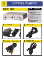
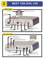
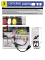
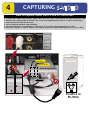
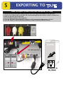
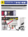
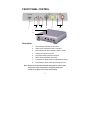
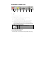
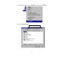
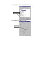
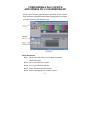
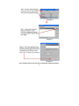
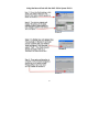
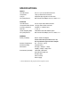
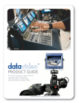
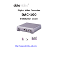
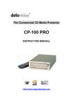
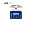
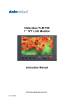
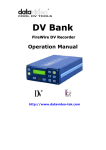
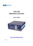
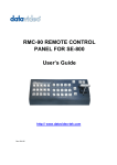
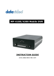
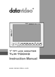
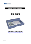
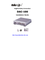
Digital Video Converter
DAC-100
Installation Guide
http://www.datavideo-tek.com
1
GETTING STARTED
DAC-100
What’s in the Box?
DAC-100
AC ADAPTER
S-VIDEO CABLE
(REQUIRES RED & WHITE RCA
AUDIO CABLE)
RCA VIDEO & AUDIO CABLE
FIREWIRE
(6 PIN MALE TO 6 PIN MALE)
INSTALLATION GUIDE
MANUAL
REGISTRATION CARD
SUPPORT INFO
1 AC ADAPTER
2 S-VIDEO CABLE
3
4
RCA VIDEO & AUDIO CABLE
FIREWIRE CABLE
6 PIN MALE TO 6 PIN MALE
2
MEET THE DAC-100
INPUT SIDE
Audio Bit Rate Selector
Input Selector
FireWire
Input/Output
Source Indicator
Audio
Bit Rate Indicator
S-Video
Input
Right Audio Input
Left Audio Input
Composite Video Input
OUTPUT SIDE
Right Audio Output
Left Audio Output
Composite Video Output
S-Video Output
Dip Switches
(Behind the Plastic Cover)
Power Switch
AC Adapter Connector
FireWire
Input/Output
3
CAPTURING
How to connect DAC-100 to capture Video from a VCR or Camcorder
1.
2.
3.
4.
5.
6.
Connect the RCA Video/audio cables from the VCR’s Line output to the input on the DAC-100.
Connect the FireWire cable to the DAC-100, connect opposite end to the PC or Mac’s FireWire Port.
Power on the DAC-100 and the VCR.
Start the Editing Software. (Not Supplied)
Press the DAC-100’s Source Button to switch it to “AV” and the A Encode Button to “16 bit”.
Go to the “Capture or Import” mode on the Editing software to begin capturing video to a PC or a MAC
PRESS
Set to “AV”
PRESS
Set to “16 bit”
Side
Input
DAC-100
FRONT
(Input)
ire
SOURCE
A ENCODE
W
re
i
F
FireWire to
PC/MAC
4
CAPTURING
How to capture Video from a VCR or Camcorder
1.
2.
3.
4.
5.
6.
Connect the S-Video cable and RCA audio cables from the VCR’s Line output to the input on the DAC-100.
Connect the FireWire cable to the DAC-100, connect the opposite end to the PC or Mac’s FireWire Port.
Power on the DAC-100 and the VCR.
Start the Editing Software. (Not Supplied)
Press the DAC-100’s Source Button to switch it to “AV” and the A Encode Button to “16 bit”.
Go to the “Capture or Import” mode on the Editing software to begin capturing video to a PC or a MAC.
PRESS
Set to “AV”
PRESS
Set to “16 bit”
DAC-100 Input Side
SOURCE
ire
eW
A ENCODE
S-Video
r
Fi
FireWire to
PC/MAC
5
EXPORTING TO
How to Export Video from the computer to Tape
1.
2.
3.
4.
5.
6.
Connect the RCA Video/audio cables from the VCR’s Line input to the output on the DAC-100.
Connect the FireWire cable to the DAC-100, connect the opposite end to the PC or Mac’s FireWire Port.
Power on the DAC-100 and the VCR.
Start the Editing Software. (Not Supplied)
Press the DAC-100’s Source Button to switch it to “DV” and the A Encode Button to “16 bit”.
Go to the “Export” mode on the Editing software to begin exporting video to the VCR.
PUSH
Set to “16 bit”
PUSH
Set to “AV”
DAC-100 Output Side
ire
SOURCE
A ENCODE
W
re
i
F
FireWire to
PC/MAC
6
EXPORTING TO
(
)
How to Export Video from the computer back to Tape
1.
2.
3.
4.
5.
6.
Connect the S-Video and RCA audio cables from the VCR’s Line input to the output on the DAC-100.
Connect the FireWire cable to the DAC-100, connect the opposite end to the PC or Mac’s FireWire Port.
Power on the DAC-100 and the VCR.
Start the Editing Software. (Not Supplied)
Press the DAC-100’s Source Button to switch it to “DV” and the A Encode Button to “16 bit”.
Go to the “Export” mode on the Editing software to begin exporting video to the VCR.
Set to “16 bit”
PUSH
Set to “16 bit”
PUSH
Set to “AV”
REAR VIEW
DAC-100 Output Side
SOURCE
A ENCODE
ire
W
re
Fi
FireWire to
PC/MAC
The Important Notice of Safety Instruction
and Radio & TV Interference
1.
Read all of these instructions and save them for later reference.
2.
Follow all warnings and instructions marked on the products.
3.
Unplug this product from the wall outlet before cleaning. Do not use
liquid or aerosol cleaners. Use a damp cloth for cleaning.
4.
Do not use this product near water.
5.
Do not place this product on an unstable cart, stand or table. The
6.
Slots and openings on the cabinet and the back or bottom are
product may fall, causing serious damage to the product.
provided for ventilation. To ensure reliable operation of the product
and to protect it from overheating, do not block or cover these
openings. The openings should never be blocked by placing the
products on a bed, sofa, rug or other similar surface. This product
should never be placed near or over a radiator or heat register. This
product should not be placed in a built-in installation unless proper
ventilation is provided.
7.
This product should be operated from the type of power source
indicated on the marking label of the AC adapter. If you are not sure
of the type of power available, consult your dealer or local Power
Company.
8.
Do not allow anything to rest on the power cord. Do not locate this
product where the cord will be walked on.
9.
If an extension cord is used with this product, make sure that the total
of the ampere ratings on the products plugged into the extension cord
to not exceed the extension cord ampere rating. Also, make sure that
the total of all products plugged into the wall outlet does not exceed
15 amperes.
1
10.
Never push objects of any kind into this product through cabinet slots
as they may touch dangerous voltage points or short out parts that
could result in a risk of fire or electric shock. Never spill liquid of any
kind on the product.
11.
Except as explained elsewhere in this guide, don’t attempt to service
this product yourself. Opening and removing those covers that are
marked “Do Not Remove” may expose you to dangerous voltage
points or other risks. Refer all servicing on those compartments to
service personnel.
12.
Unplug this product from the wall outlet and refer servicing to
qualified service personnel under the following conditions:
A.
When the power cord or plug is damaged or frayed.
B.
If liquid has been spilled into the product.
C.
If the product has been exposed to rain or water.
D.
If the product does not operate normally when the operating
instructions are followed. Adjust only those controls that are
covered
by
the
operating
instructions
since
improper
adjustment of other controls may result in damage and will often
require extensive work by a qualified technician to restore the
product to normal operation.
E.
If the product has been dropped or the cabinet has been
damaged.
F.
If the product exhibits a distinct change in performance,
indicating a need for service.
2
Service and Support
It is our goal to make your products ownership a satisfying experience. Our
supporting staff is available to assist you in setting up and operating your
system. Please refer to our web site www.datavideo-tek.com for answers
to common questions, support requests or contact your local office below.
Datavideo Corporation (USA)
12300-U East Washington Blvd., Whittier, CA 90606 USA
Tel: +1 562 696 2324
www.datavideo.us
Datavideo Technologies Europe BV
Californiedreef 263565 BL Utrecht, The Netherlands
Tel: +31 30 261 9656
www.datavideo.info
Datavideo UK Limited
Unit 2 Waterside Business Park, Hadfield, Glossop, Derbyshire SK131BE UK
Tel: +44 1457 851000
www.datavideo.info
Datavideo Technologies Co., Ltd.
10F, 176 Jian-Yi Rd, Chung Ho City, Taipei Hsien, Taiwan 235
Tel: +886 2 8227 2888
www.datavideo.com.tw
Datavideo Technologies China Co.
2F-D, 2 Lane 777, West Guangzhong Rd, Zhabei District, Shanghai, China
Tel: +86 21 5603 6599
www.datavideo.cn
Datavideo Technologies (S) PTE Ltd.
100 Lor 23, Geylang Rd, #01-03 D’Centennial, Singapore 388398
Tel: +65 6749 6866
www.datavideo.sg
3
RADIO & TELEVISION INTERFERENCE
UNITED STATES. The equipment described in this guide generates and
uses radio frequency energy. If it is not installed and used in
accordance with the instructions in this guide, it may cause
interference with radio and television reception.
This equipment has been tested and found to comply with the limits for
a Class B digital device, pursuant to Part 15 of the FCC Rules. These
limits are designed to provide reasonable protection against harmful
interference in a residential installation. This equipment generates,
uses and can radiate radio frequency energy and, if not installed and
used in accordance with the instructions, may cause harmful
interference to radio communications. However, there is no guarantee
that interference will not occur in a particular installation. If this
equipment does cause harmful interference to radio or television
reception, which can be determined by turning the equipment off and
on, the user is encouraged to try to correct the interference by one or
more of the following measures:
Reorient or relocate the receiving antenna.
Increase the separation between the equipment and receiver.
Connect the equipment into an outlet on a circuit difference from that to
which the receiver is connected.
Consult the dealer or an experienced radio/TV technician for help.
If necessary, you should consult your dealer or experienced radio/television
technician for additional suggestions. You may find helpful the following
booklet, prepared by the Federal Communications Commission: How to
4
Identify and Resolve Radio-TV Interference Problems. This booklet is
available from the United States Government printing office, Washington,
D.C. 20402. The booklet number is 004-000-00345-4.
Note: Changes or Modifications not expressly approved by the party
responsible for compliance could void the users right to operate this
equipment.
Peripheral used in conjunction with this equipment must be connected via
shielded interface cables. Use of unshielded interface cables may result in
interference to radio and TV reception, and may void the user’s right to
operate this equipment.
Declaration of Conformity
Model Number: DAC-100
Trade Name: Datavideo
Responsible: Datavideo Corporation (USA)
Address: 12300-U East Washington Blvd., Whittier,
CA 90606 USA
Telephone: (562) 696-2324
This device complies with Part 15 of the FCC Rules. Operation is
subject to the following two conditions:
(1) This device may not cause harmful interference.
(2) This device must accept any interference received, including
interference that may cause undesired operation.
5
CONTENTS
Important Notice ------------------------------ 1
Service and Support --------------------------- 3
Radio & Television Interference-------------- 4
Introduction ------------------------------------ 7
Front Panel Control ---------------------------- 8
Rear Panel Control ---------------------------- 9
Important Notice for editing systems ------- 10
Configuring a DAC-100 with
Avid DV Xpress 3.5 on Windows XP---------- 14
Specifications ---------------------------------- 18
6
INTRODUCTION
Bi-Directional DV to Analog Video Converter
DV to Analog / Analog to DV
The DAC-100 is a simple, competent solution for encoding video and audio
back and forth between analog tape and DV in both the Mac and PC
platforms.
Using the DAC-100 to convert analog to DV let’s you maintain the quality of
your analog tape without generation loss.
Key Features
Supports DV, S Video - Y/C, Composite inputs and outputs for easy
conversion across platforms
Video Comb Filter for High Quality Video
Selectable digital audio sampling rate at 12-bit 32KHz or 16-bit 48KHz
Selectable Audio Decoding at 32KHz, 44.1KHz and 48KHz
Selectable 0 IRE / 7.5 IRE black level setting
Compatible with DV (iLink), Digital 8, Video 8, Hi8, VHS, S-VHS,
VHS-C and S-VHS-C formats
Encode to or decode from the Mac environment
FireWire In and out
Works with PC Windows 98SE/ME/2000 and XP
7
FRONT PANEL CONTROL
1
2
3
4
5
6
7
8
Description:
1.
6-Pin FireWire interface for DV In/Out
2.
Video source indicators for DV or AV input
3.
LED indicators for Audio encoder 12-Bit or 16-Bit
4.
S-Video (Y/C) input connector.
5.
Composite Video input RCA connector
6.
Stereo Audio input RCA connectors
7.
Push button to select 12-Bit or 16-Bit Audio encoding
8.
Push button to select video input source DV or AV
Note: Please wait 5 seconds for the LED ready status to come on after
you push the video source button. The system needs a few
seconds to recognize a new video source setting.
8
REAR PANEL CONNECTION
1
2
3
4
5
6
7
Description:
1. Stereo Audio output RCA connectors
2. Composite Video output RCA connector
3. S-Video (Y/C) output connector
4. Mode DIP switch (Reboot the DAC-100 if you change a DIP Switch)
S1. PAL or NTSC (PAL-ON, NTSC-OFF)
S2. 7.5 IRE / 0 IRE (0 IRE-ON, 7.5 IRE-OFF).
Please note: 0 IRE is most often used in Japan. 7.5 IRE is used elsewhere.
S3. Auto / Manual DV Decode or Encode (Default at Manual Mode)
(*. Manual Mode (S3 -- OFF): select the input video manually, refer to Page 8)
(*. Auto Mode (S3 -- ON) will enable protocol communication with editing system)
S4 & S5 for NTSC and PAL video system
ON
S4
ON
OFF
S4
ON Windows ME / XP
OFF Windows 98, Windows 2000
S5
Normal Mode for DV Cam, MAC OS
S6. Reserved, set normal OFF.
5. 6-Pin FireWire interface for DV In/Out
6. DC Input Jack (+ 5VDC / 6Watts)
7. Power switch (Note: Turn-on DAC-100 before booting the PC/MAC editing software.)
9
IMPORTANT NOTICE FOR PC/MAC
EDITING SYSTEMS
1.Please shut down all resident programs in your PC for better editing
performance. Such as the Anti-Virus program, screen saver, system
power management software… etc.
2.Enable the Disk DMA function in windows to improve system HDD
access performance
To install a proper HDD DMA or Bus Master driver will improve your PC
system’s overall performance.
Please refer to following web site for various PC main board chipset
drivers, which could be Disk DMA driver related to your system.
INTEL chipset:
http://www.intel.com/intel/nav/support.htm?iid=Homepage+Head
erSupport&
VIA chipset:
http://www.via.com.tw/drivers/index.htm
ALI chipset:
http://www.ali.com.tw/eng/support/support_driver.htm
SIS chipset:
http://www.sis.com/support/driver/index.htm
Please make sure to download the right chipset driver for your system
If there is no any main board Chipset driver in your system, you
may enable DISK DMA function in Windows device driver section.
Please refer to the installation procedures below for windows 98.
Note: Windows ME has similar DISK DMA setting procedure as Windows 98
below; The DISK DMA are enabled as default setting in both Windows
XP and Windows 2000 operating system.
10
S1. On windows desktop, click on “My computer” and check the “properties”
S2. Click on “Device manager”
Click on Device Manager
11
S3. Click on ”Disk drives” and Select “Generic IDE Disk” and then click on
“Properties”
Click on “Properties”
S4. Select “Setting” and enable “DMA” and click on “OK”.
Enable “DMA”
12
3.To work with MAC Final cut pro (Recommended):
1). Select "Preferences" from Final Cut Pro menu
2). Select "General" page.
3). Uncheck "Abort capture on dropped frame"
4). Uncheck "Abort capture on time code break" for Final cut pro
5). Click OK button
4. For Avid XpressDV Users:
1). Set the Dip switch to Windows 2000 mode (refer to page 9)
2). Launch the Avid XpressDV Software.
3). Check “Setting” and select the “Generic” DV Basic Device in the “Deck
Configuration” menu.
*. Note: Please refer to following pages of the set up procedure for Avid
XpressDV 3.5 / windows XP user.
13
CONFIGURING A DAC-100 WITH
AVID XPRESS DV 3.5 ON WINDOWS XP
Screen 1 above shows a typical desktop in Xpress DV 3.5, key areas for
setup have been highlighted. Please follow the steps below to configure
your DAC-100 for use with Xpress DV 3.5.
Setup Procedure:
Step 1. Connect your DAC-100 to your computer via FireWire.
(IEEE/1394 cable)
Step 2. Turn on your DAC-100 converter.
Step 3. Turn on your Windows computer.
Step 4. Launch the Avid Xpress DV software.
Step 5. Open an existing project or create a new one.
14
Note: The DAC-100 uses the same deck configuration setting as the DAC-2
15
Using the Record Tool with the DAC-100 in Xpress DV 3.0
16
17
SPECIFICATIONS:
INPUTS
*S-VHS sources
*Composite
*C-Sync
*DV (iLink) Source
Y/C in: 4—pin 75 ohm DIN connector
1.0Vp-p 75ohm RCA connector
Composite Sync signal in for Gen-lock
OUTPUTS
*S-VHS Source
*Composite Video Source
*Frequency Response
*DG, DP
*Audio Sampling Rate
*DV (iLink) Source
Y/C out 4-pin 75ohm DIN connector
1.0 Vp-p 75ohm RCA connector
4.5 MHz +/- 3 dB (DV input)
+/- 3%, 3°
12bit 32KHz and 16bit 48KHz option
GENERAL
Power (Included)
Data Transfer Rate 25Mbps, PAL 4:2:0 / NTSC 4:1:1
Data Transfer Rate 25Mbps, PAL 4:2:0 / NTSC 4:1:1
DC 5V / 6.0W AC Adapter
Caution: DAC-100 requires DC 5 Volt +/- 4%,
Use only Datavideo approved Power Adaptor.
Ambient Temperature
Ambient Humidity
Dimensions
Accessories (included)
32° - 131°F (0° - 55°C)
Less than 90 %
6.15”(W) × 6.0”(D) × 1.6”(H)
156(W) × 150(D) × 40(H) m/m
1.8m IEEE 1394 cable
3R to 3R RCA cable set
S-Video cable
User’s manual
Power supply
*. All the trademarks are the properties of their respective owners
18