1
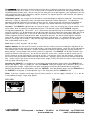
PARALLEL
USER MANUAL
NOTE: This product uses a visible laser diode as the light source. It is characteristic of laser
light that it contains a high amount of power in a small beam cross section. This makes it
potentially hazardous to the eyes. We have chosen to make the PARALLEL with the
lowest practical power level. This power level, FDA Class II, is considered a hazard only if
stared into. An accidental glance of the beam is not considered hazardous.
Packing list :
Projection box
2 AA batteries ( installed )
3 small reflectors
1 large reflector
rubber band harness
1 hex wrench
USE ( all items mentioned in the following instructions are included unless noted)
Basic. In use, the PARALLEL consists of a laser projection box and a reflector. The reflection of the laser beam
creates a red dot on the top of the projection box. The position of this dot is a direct indicator of the alignment of the
reflector to the surface that the projection box is sitting on. If the reflector is perfectly parallel to the surface that the
PARALLEL is sitting on (the reference surface), the red dot will be centered over the hole that the laser beam is
projected out of. Any error in parallelism of the reflector to the reference surface will cause the dot to be displaced
from this ideal position.
Install a reflector, basic. One of the many ways we have optimized the price/performance of the PARALLEL is to
use plain un-mirrored glass for the reflectors. The proportion of light reflected is quite sufficient, the reflectors are
inexpensive and very flat, and they are as accurate as first surface mirrors in use since the reflection off both front and
rear surfaces coincide when everything is aligned parallel. The small reflectors measure 1” x 3” x .04”, the large 5 1/2”
x 2 1/2” x .04”. One of the small reflectors is backed with a white paper label. Since light passes through the
reflectors, this label prevents stray reflections from the glass elements of the lens. Anything nearly opaque can be used,
and may be wanted on the negative carrier reflectors to prevent reflections off condensers, or other lighthead
glassware.
Lens reflector. For a quick check of lens alignment you can simply hold one of the reflectors against the front rim of
the enlarging lens. If alignment is needed, you can then fasten the reflector to the lens front by use of the rubber
band assembly provided. This allows hands-free use of the PARALLEL.
An odd looking thing, this is a rubber strip with two small rubber bands looped around it, the
strip joined by passing through a metal washer. Slip the large band around the outside of the
enlarging lens barrel and then move the two small bands to opposite sides. Slip the reflector
through the loop of each of the small bands. Move the large band up or down the lens barrel
adding or lessening tension so that the small bands gently hold the reflector to the front rim of
the lens. [[You can adjust the length of the large band by moving the washer position - most
easily if you stretch the rubber at the same time. The dynamics of the rubber allow adjustment
yet hold position when stretched around an object.]] The reflector does not sit on the front element of the lens, but
on the rim of metal that sticks out past the glass. One of the small reflectors has a paper label on one side (use as the
back side) which prevents additional reflections from glass parts behind the reflector - such as the lens elements or
condensers. If this trouble occurs with the other reflectors, any nearly opaque material from paper to tape can be
used to prevent it.
Negative carrier reflector. First remove the lens so that the projected beam can directly reflect from the bottom
surface of a reflector in the negative carrier. The standard reflector will fit into any glass-less carrier up to 6 cm. by
whatever width. Open the carrier, remove any negatives, and set the reflector across the negative area. Be certain
that all surfaces are clean. Do not cause high local pressure to the reflector, such as squeezing it between a carrier
plate and locating pins, since it may break and leave glass chips in the enlarger.
For glass-less carriers up to 5 x 7, use the large reflector in place of the negative as described above.
You can omit the reflector with glass carriers. Use the glass itself as the reflector.
The DOT. Once a reflector is in place, move the projector box to the approximate center of the easel and switch on
the laser. Move the box around until the beam hits the reflector. The red dot will appear on or near the projector
box when you are in place under the reflector. If you look closely at the dot you will see that it has concentric rings
around it. The rings are formed by optical diffraction effects as the beam passes through the various openings in the
projector box. Diffraction is much more obvious with laser light.
If the reflector is mounted to a perfectly aligned part of the enlarger, the dot will fall perfectly back onto the small hole
in the middle of the target area - you may only see the diffraction rings surrounding the hole. If you tilt the PARALLEL,
the dot will move out of the hole onto the surrounding target area.
Dot continued. Make adjustments to the enlarger until the dot is as perfectly centered on this hole as possible. You
are likely to find that even as much as 1/16” or more error in the position of the dot (with the enlarger head 20” up)
still provides pretty flawless prints. We can’t tell you how close you have to get alignment, your requirements will vary
with enlarger light source (grain definition), negative and print size, negative graininess and resolution, lens aperture,
and probably a bunch of other things.
Adjustments typical. Any enlarger can be adjusted to a reasonable degree of alignment perfection. Some enlargers
come with a variety of adjustments, others claim permanent perfection without adjustments. The adjustment
procedures should be outlined in the enlarger’s owners manual. Please contact the manufacturer or distributor of
your enlarger for instructions if yours are missing. Enlargers truly without adjustments may require shimming.
Accuracy. The PARALLEL is adjusted close to a minute of angle - a fancy way of saying that 44” from the box, it will
still be within .015” of a perfectly true perpendicular beam. The reflection system of the PARALLEL magnifies
misalignment proportionally. For instance - at 15” distance from the projection box to the reflector (easel to negative
carrier for instance) 1/16” of displacement of the dot away from the center hole of the target equals .002” per inch of
negative width out of parallelism. In the case of 35mm film this would mean that the entire negative (except for
inherent negative curvature) would be within .003” of parallel to the easel! For 4x5 the whole negative would be
within .010”. Other errors can be approximated by the formula, Error distance ÷ 2 ÷ projection distance = out of
parallel in inches (per inch of width). Note that the larger the projection distance the greater is the dot position
error, and therefore easier to see!
Care. Keep in a clean, dry place. Do not drop.
Replace batteries. Use the small hex wrench to remove the four stainless steel screws holding the top plate on the
box. Make certain that the switch on the end of the box is turned to the off position. Gently pry out the old batteries
with something like a small screwdriver. Snap the new batteries into place in the battery box - paying attention to
battery polarity. Do not tamper with the laser system or its alignment. The PARALLEL will be most accurate if you
replace the lid with a little extra care. Just so that our references are the same - position the box in front of you so
that the words on the lid read normally, running left to right. Start the four screws into their threads. Gently push
the lid away from you toward the back of the box and to the left - aligning it against the back of the box and the left
side. Gently snug the two screws on the left end (near the target), and run the other two screws (switch end) down
until just gently contacting the lid.
Checking the PARALLEL. It is possible that at some point you would become concerned that the PARALLEL had
become mis-aligned. There is a simple test. Place the PARALLEL under your enlarger with a reflector in place, just as
when aligning the enlarger. Make certain that some misalignment causes the dot to be outside the target hole.
Watching the position of the reflected dot, rotate the PARALLEL. If the dot position rotates with the PARALLEL then
the PARALLEL is mis-aligned. If the dot position stays in the same place, then the PARALLEL is fine.
Extras. If you have a negative carrier larger than 5x7 please contact us. We can supply a reflector 9” x 3” x .04” for
a small additional charge. Larger strips quoted.
END LABEL
√
TOP LABEL
1509 Sunnyside • Loveland • CO 80538
www.versalab.com
tel. 970.622.0240 fax 970.622.0239
email: [email protected]