1
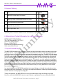
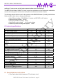
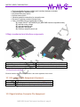
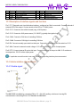
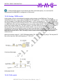
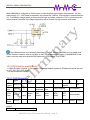
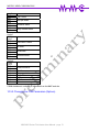
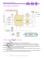
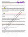
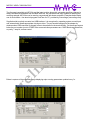
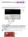
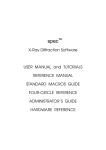
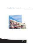
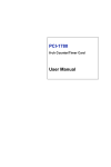
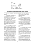
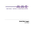
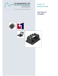
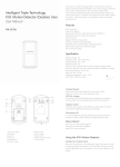
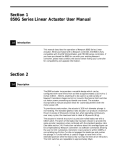
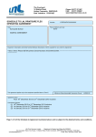
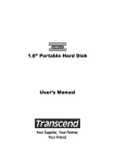
METRIC MIND CORPORATION
MMC4000LV
MMC4000HV
EV Fluid Heater User Manual
Version 0.9 - Preliminary
MMC4000 Series Fluid heater User Manual - page 1
METRIC MIND CORPORATION
Publisher
Metric Mind Corporation 10117 SE Sunnyside Rd., Clackamas, OR 97015 USA +1-503-477-6071
www.metricmind.com
[email protected]
Date
Nov 15 2014
© 1999-2015 Metric Mind Corporation.
Copyright
Updates
All rights reserved.
Distributing or copying this document whole in part or using excerpts of its content without written
permission of its owner (Metric Mind Corporation, MMC) is prohibited. Violators are liable for damages
resulted from failure to comply with applicable copyright laws.
MMC reserves right to periodically update user manual with new information or error corrections. All
changes will be documented in the revisions section of this manual.
Disclaimer
The hardware described in this manual is not a consumer product. It is OEM part meant for installation and service by qualified
personnel. Operation involves high temperature, poisonous liquid and lethal voltages. UNDER NO CIRCUMATANCES,
EXPRESSED OR IMPLIED, MMC WILL BE HELD LIABLE FOR ANY DIRECT OR CONSEQUENTIAL DAMAGES TO LIFE,
PROPERTY OR HARDWARE, OR LOSS OF BUSINESS OR PROFITS RESULTING FROM USAGE OF THIS PRODUCT. USER
ASSUMES ALL THE RISK ASSOCIATED WITH USE OF THIS PRODUCT.
REVISIONS
REV
DATE
NAME
COMMENT
01
Nov 15 2014
Victor Tikhonov
Initial Release
Warning and Caution labeling
The following internationally recognized icons are used in this manual to indicate danger, warning and caution
conditions. Paying attention, observing and following safety rules is sole responsibility of the user.
General Prohibition
General Warning
Do Not Turn On
Warning - High Voltage
Disconnect or Turn Off
Warning - Magnetic Field
Do Not Touch - High Voltage
Warning – hot liquids
Relevant Information
Hint
MMC4000 Series Fluid heater User Manual - page 2
METRIC MIND CORPORATION
TABLE OF CONTENTS
1 Foreword .................................................................................................................................................. 4
2 List of Abbreviations ................................................................................................................................. 4
3 Safety and Warning Instructions ............................................................................................................... 4
3.1 Safety Instructions for Electrical Systems .......................................................................................... 5
3.2 Safety instructions for fluid heating systems ...................................................................................... 6
4 Model Identification................................................................................................................................... 6
5 Scope of Delivery ..................................................................................................................................... 7
6. Manufacturer Contact Information for ordering spare parts ...................................................................... 7
7 Proper Intended Use................................................................................................................................. 7
8 Technical specifications............................................................................................................................ 8
8.1 Special features and options.............................................................................................................. 8
9 Major mechanical and interface components............................................................................................ 9
10 Electrical interface .................................................................................................................................. 9
10.1 HV connector Pin Assignment (if present)........................................................................................ 9
10.2 Signal Interface Connector Pin Assignment ..................................................................................... 9
10.3 Description of interface signals and functions ................................................................................ 10
10.4 Vehicle interface internal circuits.................................................................................................... 10
10.4.1 Enable signal .......................................................................................................................... 10
10.4.2 Analog / PWM control ............................................................................................................. 11
10.4.3 CAN control ............................................................................................................................ 11
10.5 CAN interface specifications. ......................................................................................................... 12
10.5.1 CAN Messaging ...................................................................................................................... 12
10.5.2 Changing the CAN Parameters (Options) ............................................................................... 13
11 Block Diagram of the MMC4000 ........................................................................................................... 14
12 Dimensions and Installation Information ............................................................................................... 14
12.1 Installing and Connecting the Heater ............................................................................................. 15
12.2 Using USB/Fiber Optic Cable interface dongle to configure the heater .......................................... 15
13 Serial communication ........................................................................................................................... 15
14 Changing internal fuse.......................................................................................................................... 17
15 Warranty............................................................................................................................................... 18
16 Liability waver and legal disclaimer....................................................................................................... 18
MMC4000 Series Fluid heater User Manual - page 3
METRIC MIND CORPORATION
1 Foreword
Dear Customer!
You have acquired one of the most capable and sophisticated hardware capable to fulfill your performance
demands. Please keep in mind that its operation involves high temperatures (near water boiling point
100°C), poisonous liquids (ethylene glycol, aka "antifreeze") and high voltages (your traction battery
voltage). Therefore it is critical to observe safety and warning instructions and have this product installed
and serviced by qualified personnel. The MMC4000 is NOT a consumer product and thus it is not designed
to be "consumer friendly". It this is specialized OEM sub-system meant to be part of electric or a hybrid
vehicle, conventional vehicles (usually commercial trucks) requiring running heating subsystem but
restricted in idling its engine just for that purpose, or a stationary infrastructure.
Please read and understand this manual. Contact Metric Mind Corporation technical support if you have
any questions not addressed in this manual.
2 List of Abbreviations
Throughout this manual, some specific technical abbreviations are used. Their meaning is shown in the
table below.
AUX
BMS
CAN
EMI
GND
HV
LV
Auxiliary
Battery Management System
Controller Area Network
Electromagnetic Interference
Ground
High Voltage
Low Voltage*
*Throughout this manual the term "HV” or “high voltage" is used to refer to the voltage applied to the
power connector whether heater model is "low" voltage range (200...500 VDC) or high voltage range
(450...900 VDC). This is often referred to as “traction battery voltage”. Unless specifically mentioned, “low”
voltage range is still considered high voltage as far as safety context, in contrast with auxiliary 12VDC or
24VDC voltages powering internal control logic, which is referred to as “AUX”, the same voltage running
lights, wipers, radio and other such subsystems.
3 Safety and Warning Instructions
In this chapter you will find safety instructions which apply to this device and refer to assembly,
start-up and running operation in the vehicle. These instructions mostly apply to stationary application as
well. Always read and observe them in order to maintain personal safety and avoid damage to the device
and other property!
The following generally applicable safety measures have been developed based on the knowledge
MMC4000 Series Fluid heater User Manual - page 4
METRIC MIND CORPORATION
of the manufacturer. They are not complete, they can be supplemented by local and/or country-specific
safety instructions and guidelines for accident prevention. The system integrator and/or distributor of the
device must therefore supplement the present general safety instructions by country-specific and local
guidelines.
3.1 Safety Instructions for Electrical Systems
High voltage! Danger to life!
) Do not touch any HV wiring unless you're assured there is no high voltage applied to the heater!
) The device may only be connected by a qualified electrician!
Potential Damage to the traction battery or power source!
) Make sure the battery or other power source supplying heater (fuel cell, solar panel, generator
and such) has enough power and current capability to sustain prolonged operation. While the heater has
low voltage lockout feature, it will not prevent your battery from overdischarging if left unattended.
) You must make sure that the battery voltage is within working voltage range of chosen device. If
your battery voltage falls in overlapping range (450VDC to 500VDC) LV or HV model can be used with
identical outcome.
Potential Damage to infrastructure:
) Only use compatible and high-quality power cable and connector!
) Make sure the power leads are of sufficient cross-section area to continuously carry max.
working current.
) Make sure crimp terminals in power connector are secured - loose crimp will cause local
overheating and arcing resulting in melting near by plastic parts and potentially causing fire.
) Make sure to protect optical interface parts in case heater is washed from outside. Avoid direct
contact with road debris, salt or corrosive liquids.
) The heater features galvanic isolation between AUX voltage and HV. Connecting traction battery
to device’s Ground terminal will not damage the MMC4000 but may destroy other control circuits in the
vehicle relying on the isolation between HV and AUX (chassis).
Potential Damage to the MMV4000:
) Make sure maximum voltage applied to power input of heater does not exceed specification.
) Make sure AUX power and control voltages are within specified limits. Exceeding absolute
maximum limit will damage heater control electronics.
) There are no user serviceable parts inside other than power fuse. In case software monitor
reports error, contact MMC tech support. Most of these errors can be cleared and issues resolved remotely.
) If your device is equipped with flow sensor, DO NOT defeat its operation. Doing so may leave
heating elements powered up while there is insufficient fluid flow, which may lead to elements burning out
before stalled liquid will trigger overtemperature protection.
) The MMC4000 is internally fused. Under no circumstances should you bypass, upgrade or
replace fuse with higher current rating. If power fuse keeps blowing, you must determine root cause of
malfunction. The fuse is sized with enough margin not to blow under any normal working condition. In the
even of fuse blow the heater software takes a snapshot of the fault condition and stores it in non-volatile
memory. This information is user accessible (read only), and helps to determine root cause of the failure.
Mere replacing fuse will not fixing underlying problem and the same blow will likely reoccur.
MMC4000 Series Fluid heater User Manual - page 5
METRIC MIND CORPORATION
CAUTION
) Overheating of the cables! Fire hazard!
) Heater enclosure is sealed. Unauthorized opening or attempted repairs will void warranty
Generic rules when servicing any HV hardware:
) Physically unplug system power. Do not rely on relays or contactors still under software control
as any microcontroller glitch may cause inadvertent closure of power relays. Turn off the ignition and
remove key. If equipped, remove service disconnect or main power fuse
) Make sure the system cannot re-apply HV power due to software glitch or unauthorized access.
) When practical, do HV measurements with one hand - connect/disconnect test leads using spring
loaded hooks or alligator clips. Remember the current path from one hand to another lies through your
heart, while from any one hand to your feet the heart will be bypassed.
3.2 Safety instructions for fluid heating systems
) Make sure fittings are tight and fluid hoses are in good condition.
) Make sure retaining clips are used to secure hoses onto the fittings as high temperature liquid
increases pressure of vapors and insecure hoses may slip off fitting during maintenance or inspection
causing severe burns by hot ethylene glycol or water. Disassemble, service or open expansion tank for
refill only when liquid is cold.
) Use of expansion tank for safety is required. Aside of convenient point to fill up the system with
fluid, it will allow vapor to escape in case of malfunction causing fluid to boil.
4 Model Identification
MMC 4000 HV PF
P = no integrated water pump
F = no internal flow sensor
LV = Low voltage
HV = High Voltage
4000 = max power (watts)
Manufacturer identifier
The MMC4000 can be ordered without integrated fluid pump (P version) and/or without internal flow
sensor (F version) or without both (PF version). If external water pump is used, make sure the flow rate
does not exceed max 10 l/min to avoid damage to the flow sensor.
Reversing direction of fluid flow will not damage but will disable the MMC4000*.
* This does not apply to MMC4000xx-PF version
MMC4000 Series Fluid heater User Manual - page 6
METRIC MIND CORPORATION
5 Scope of Delivery
Pos Item
Qty
1
MMC4000 series heater fluid heater
1
2
MMC optic fiber to USB serial interface converter
1
3
8 circuits Ampseal interface plug
1
4
Ampseal crimp terminals
8
5
Fiber Optic cable 1.5m
2
Representative
photo
Optionally items 2-5 can be ordered from the manufacturer as spare parts
6. Manufacturer Contact Information for ordering spare parts
METRIC MIND CORPORATION
10117 SE Sunnyside Rd., STE F1211
Clackamas, OR 97015 USA
Phone: +1(503)477-6071
Email: [email protected]
Web: www.metricmind.com
7 Proper Intended Use.
The MMC4000 fluid heaters are designed to maintain set liquid temperature closed circulation loop using a
DC power source. In general, MMC4000 is meant to be installed in a battery or fuel cell powered electric
vehicle (or a boat) or a hybrid vehicle/boat, equipped with standard heater core. The MMC4000 will replace
your engine as a source of heat. It can also be used in semi-stationary applications such as - space heaters
in RVs or ground camps. It is especially usable in electric or hybrid vehicles converted from conventional
gasoline or diesel powered ones, so that all internal heating system (air ducts, blowers and controls) can
remain unchanged and only source of hot liquid replaced. For instance, one such application is heating of
the cabin of long haul trucks using on-board DC battery as tighter environmental regulations prohibit idling
large diesel engines overnight or during long stay. Also increasing numbers of ocean ports and cargo docs
prohibit fossil fuel powered trucks and other vehicles to enter their premises all together and only electric
powered ones are allowed to operate within certain radius of the port. Using MMC4000 in such vehicles
solves cabin heating issues.
In a typical installation the MMC4000 is plumbed to the same fittings on a firewall the coolant hoses from
the engine used to be connected to. This is by far the simplest modification, unlike major system redesign if
ceramic elements or heat pumps are deployed.
Though not optimized, the MMC4000 can be used as portable space heater in buildings or garages.
However, note that the MMC4000 cannot accept AC power or pulsating DC power resulting from direct
MMC4000 Series Fluid heater User Manual - page 7
METRIC MIND CORPORATION
rectifying AC mains power and will require external radiator as a heat exchanger.
The MMC400 fluid heater CANNOT be used in open loop application such as on-demand residential or
commercial running water heaters where hot liquid is not returned to the inlet of heater.
The following absolute limits are set for the operation of the MMC4000 heater. Operating outside these
limits can lead to shut down or damage to the heater:
) Max. DC input voltage 500 VDC for LV version and 900 VDC for HV version
) Max AUX supply voltage 32 VDC
) Max temp control DC voltage 5VDC
) Max Enable control voltage < AUX supply voltage
) Maximum pressure cooling water system 1.0 bar
8 Technical specifications
Parameter
Min. input voltage (PWR)
Max. input voltage (PWR)
Min. AUX voltage
Max. AUX voltage
Max. temp control voltage (analog input)
Max. DC input power (adjustable)
CAN 2b 11 bit identifier, comm. speed
(default)
Power - control isolation resistance min
(initial)
Fluid flow rate*
Reverse polarity (HV power) protection
Dry Weight LV and HV version
Dry Weight LVP and HVP version
8
32
5
4000
Unit
VDC
VDC
VDC
VDC
VDC
W
125/250/500/1000
kbps
1
GOhm
600
Yes (fuse)
1.2
1.0
l/hr
--kg
kg
Yes
Yes (optional)
-
AUX power voltage
8...32
VDC
IP protection
Enclosure Body Height
Enclosure Body Width
Enclosure Body Length
Insulation testing (AC input / DC output)
Power inlet over-voltage protection
IP54
88
334
250
2
264
--mm
mm
mm
kV
V
Overtemperature protection
Insufficient fluid flow protection
MMC4000LVx
200
500
MMC4000HVx
450
900
* parameter does not apply to LVP or HVP version
8.1 Special features and options
) Fiber Optic cable isolation between a PC and heater circuit
MMC4000 Series Fluid heater User Manual - page 8
METRIC MIND CORPORATION
) Field upgradeable firmware via fiber optic interface (hardware included)
) External output for diagnostic LED
) No internal fluid pump option
) No flow sensor option
) Vibration-resistant construction for automotive use
) Reverse HV polarity protected (internal fuse)
) 5 way controllable (user programmable modes):
- By simple ON/OFF via ENABLE input (MES RM3/4 series compatible mode)
- By external analog voltage
- By external potentiometer
- By external PWM signal
- By CAN from external control unit
9 Major mechanical and interface components
4
5
6
2
3
1. Cooling water inlet (Ø 19 mm or 3/4")
3. HV battery power connector (input)
5. Fiber optic interface transmit port
1
2. Cooling water outlet (Ø 19 mm or 3/4")
4. Interface connector (input/output)
6. Fiber optic interface receive port
10 Electrical interface
Electrical interface and pinout of connectors is the same regardless of the model.
10.1 HV connector Pin Assignment (if present)
Pin number
1
2
Function
High voltage power input positive (always RED wire)
High voltage power input negative (always BLUE wire)
10.2 Signal Interface Connector Pin Assignment
MMC4000 Series Fluid heater User Manual - page 9
METRIC MIND CORPORATION
Pin
1
3
5
7
Name
FLT
CL15
CANH
ANA
Function
Fault out (LED)
AUX power input
CAN High
Analog control input
Pin
2
4
6
8
Name
CL31
CANL
EN
POT+
Function
AUX power return (GND)
CAN Low
Heater ENABLE
Potentiometer bias
10.3 Description of interface signals and functions
Pin 1 FLT. Diagnostic and visual indication interface – configured as 10mA current sink. Connect cathode of
external LED to this output. Connect anode of the LED to C15 AUX power.
Pin 2 CL31. Connect to the vehicle chassis (neg. of AUX power)
Pin 3 CL15. Connect to AUX power source (12…24VDC), typically after ignition key.
Pin 4 CANL. Connect to CAN low of controlling CAN bus.
Pin 5 CANH. Connect to CAN high of controlling CAN bus.
Pin 6 EN. Connect normally open switch to this input. Connect the other terminal of the switch to CL15.
Pin 7 ANA. Connect to external control voltage. 0…5V corresponds to 0…100% of output power.
Pin 8 POT+ Connect external 5k pot to this input. Connect other side of the pot to ANA. 0…5k resistance
corresponds to 100…0% of the output power.
If a particular control function is not used, leave corresponding interface pins unconnected.
10.4 Vehicle interface internal circuits
10.4.1 Enable signal
The MMC4000 is enabled by connecting EN to +12...+24 VDC auxiliary vehicle net. Leaving EN
unconnected or connecting EN to CL31 disables the MMC4000.
MMC4000 Series Fluid heater User Manual - page 10
METRIC MIND CORPORATION
In CAN mode EN signal is not monitored and CAN control takes priority. You can leave EN
unconnected if the MMC4000 is configured for CAN control.
10.4.2 Analog / PWM control
Analog power control is accomplished by applying analog voltage to Ana/PWM input. This can be
implemented two ways: if your vehicle controlled has DAC output with 0...5 VDC output voltage range, you
can directly apply it to the MMC4000 Ana/PWM input. 0...5VDC corresponds to 0...100% of preconfigured
max power. To improve noise immunity there are ~0.7V dead zones designed to the analog control circuitry,
e.g. MMC4000 will not will start outputting power when analog voltage reach 0.7 VDC, and will output 100%
power when analog voltage is at ~4.3 VDC or above. If you don't have any analog voltage source, there is
special output (POT+) to bias external 5k variable resistor. You can use any linear potentiometer by
connecting one fixed end to the bias power and viper to the ANA input. Leave the other fixed end of the
potentiometer unconnected. Reducing resistance from 5k to 0k (with some dead zone margins) increases
MMC4000 power from 0% to 100%. This way in case of broken control pot connection output power is
reduced to zero.
ANA input can also receive 0...5 VDC PWM signal within 150...5000 Hz frequency range. The low pass RC
filter on the input has -3dB cutoff frequency of ~130 Hz.
Control pot bias supply
Analog input circuit
10.4.3 CAN control
MMC4000 Series Fluid heater User Manual - page 11
METRIC MIND CORPORATION
When MMC4000 is configured for CAN control, no other interface signal need to be connected. You only
need to apply +12...+24V power to the heater, and connect the CAN bus. CAN interface is isolated from the
HV. To avoid high voltage spikes on the transceiver input and output, make sure CL31 is connected to the
vehicle chassis, otherwise overvoltage suppressors will not function for high common mode noise.
The CAN transceiver is not internally terminated by default, allowing MMC4000 to be a middle node
on the CAN bus. However, there is provision on the PCB for the node termination. If the MMC4000 is last
node on the bus used must short two SMT pads on the PCB labeled "CAN TERM."
10.5 CAN interface specifications.
) CAN 2.0B comm. protocol, 11 bit identifier. CAN speed default is preset to 125kbps and can be user set
to (125 / 250 / 500 / 1000 kbps).
) No bus termination installed.
10.5.1 CAN Messaging
Byte#
->
7C1h
Control
7C2h
Vars
7
6
5
4
3
DLC=6
DLC=8
7C4h
Status
DLC=3
1
Battery PWR
request
DLC=3
7C3h
Fixed
2
Acces
s
counte
r
Model
type
0
EN
Temp
computed
Ana %
Req.
PWR computed
HV computed
SW
version
Main
Fuse
MFG
Week
MFG
Year
Serial number
Limits 2
Limits 1
Limits 0
7C4H
MMC4000 Series Fluid heater User Manual - page 12
Limits 0
METRIC MIND CORPORATION
byte 0
Bit 7
Bit 6
Bit 5
Bit 4
Bit 3
Bit 2
Bit 1
Bit 0
Limits 1
7C4H
byte 1
Bit 7
Bit 6
Bit 5
Bit 4
Bit 3
Bit 2
Bit 1
Bit 0
Limits 2
7C4H
byte 2
Bit 7
Bit 6
Bit 5
Bit 4
Bit 3
Bit 2
Bit 1
Bit 0
IGBT status
ANA pot status
Limitation status
Temp. sensor status
CAN comm. status
HV limits
PWM limits
elements status
Crow bar source
Fluid flow
Temp reached
Pump EN
3.3V power
FLT status
EN status
CANdb database is available for download from the MMC web site.
10.5.2 Changing the CAN Parameters (Options)
MMC4000 Series Fluid heater User Manual - page 13
METRIC MIND CORPORATION
11 Block Diagram of the MMC4000
12 Dimensions and Installation Information
For installation of the heater, the following points must be strictly adhered to:
) All models featuring fluid flow sensor must be installed in correct orientation according to the
arrows molded on the enclosure. Installing heater at wrong angle will prevent sensor from detecting the
flow and disable the heater*.
) The air-cooled version must be installed so that a constant fresh air supply is guaranteed. This
has a direct influence on the power of the device (de-rating).
) The mechanical fixings must be arranged so that the device is fitted firmly and in a way that is as
vibration-proof as possible.
) The cable feeds and cooling water tubes should have sufficient space for routing and plumbing,
and may under no circumstances sit in contact with sharp-edged components.
MMC4000 Series Fluid heater User Manual - page 14
METRIC MIND CORPORATION
12.1 Installing and Connecting the Heater
The MMC4000 heater is intended to be installed on a firewall in the engine compartment, but can be
installed on any vertical surface or supporting brackets providing upright position, Tilt up to 15° in any
direction is allowed*.
The MMC4000xx heaters are equipped with flow rate sensor which is operational only if the
heater is installed in correct vertical position. Heater should not be installed in horizontal or any other
orientation than vertical. It is allowed to install MMC4000xx heater in any position if the fluid flow rate
sensor is disabled in the software. In such configuration is a responsibility of the user to make sure fluid
chamber is always filled with fluid, and there is sufficient fluid flow while heater is electrically enabled.
Note that integrated fluid pump is not self-priming. Make sure the air is removed from the coolant
loop before operating heater.
Be aware that in case of loss of liquid heating elements exposed to the air will burn up within
a few seconds. With liquid present but not moving, heater may protect itself from burning out, but
depending on the ethylene glycol and water mixture ratio the fluid might boil before temp protection kicks
in, this will cause rapid pressure increase and unless expansion tank is used - burst of hot liquid, damage to
the seals and water pump. In case of internal leak due to increased vapor pressure, controller circuit may
get damaged.
Rapid temperature increase due to this condition will be detected and stored in memory for service and
troubleshooting purposes and damaged heating elements or control circuit due to insufficient fluid flow or
absence of fluid is not covered by warranty. For this reason running heater with its flow sensor disabled is
not recommended, regardless whether internal or external water pump is used.
* If a flow sensor is disables or not present, the MMC4000 will work in any position. However, care must be
taken to ensure sufficient fluid flow. Keep in mind that in case of clogged or kinked tubes or loss of liquid
and no external means to disable heater due to insufficient flow rate, the heating elements may burn out.
12.2 Using USB/Fiber Optic Cable interface dongle to configure the heater
Because heater is installed near hot liquid, to avoid corrosion of the serial interface contacts used very
rarely and increase safety by complete galvanic isolation the heater is equipped with fiber optic interface to
a PC.
To upgrade heater’s firmware in the field, you can use any serial terminal utility allowing sending external
ASCII files such as RealTerm (also available from MMC web site).
13 Serial communication
The MMC4000 is equipped with serial port for diagnostics and field upgrades of the firmware. To prevent
contact corrosion in close proximity to hot corrosive liquid, assure absolute electrical safety and immunity to
EMI, no physical connectors or any metal parts are present, and communication is implemented via fiber
optic cables. Operation is transparent to the user, as special supplied USB/optical transceiver dongle
converts serial transmitted data to modulated optical transmission which is demodulated on the receiving
end. For full duplex operation two fiber optic cables are used.
MMC4000 Series Fluid heater User Manual - page 15
METRIC MIND CORPORATION
The firmware is supplied as ASCII file and the latest revision along with comments specifying changes is
always available for download from the MMC web site. Any serial terminal utitily capable of sending and
receiving external ASCII files can be used to communicate with heater controller. Examples below depict
one of such utilities - free terminal program RealTerm for PC, provided by Sourceforge (sourceforge.net).
Supplied serial to optical converter has USB interface. It is recognized by operating system as serial port
and automatically installs appropriate virtual port driver. The port number assigned to the adapter by
windows when USB connector is plugged in has to be selected in the terminal utility. On the screen capture
below the port number is set to COM4. Other communication parameters are: 19200 Baud rate, 8 data bits,
no parity, 1 stop bit, no flow control.
Below is capture of the main status page displaying major running parameters updated every 1s.
MMC4000 Series Fluid heater User Manual - page 16
METRIC MIND CORPORATION
To upgrade heater firmware choose "Setup" from the main window and then choose "Firmware download".
Navigate to the directory containing firmware file and click "Send File" button.
Select file
Send file
14 Changing internal fuse.
There are no user serviceable parts inside heater other than HV fuse and CAN termination jumper. The
fuse will blow in case of excessive power consumption or connecting HV in reverse. Always replace fuse
with the same type and ratings. If fuse blows, it indicates internal problem and increasing fuse rating will not
make problem go away and will only cause further damage to the power connector HV wiring and external
power source or components. Contact the manufacturer for assistance if such situation will occur.
Location of the power fuse is shown on the photo below. Fuse rating depends on the model: it is 25A for LV
version and 10A HV version.
The fuse rated for 1000VDC (Direct Current) operation. DO NOT install AC rated fuse.
FUSE
MMC4000 Series Fluid heater User Manual - page 17
METRIC MIND CORPORATION
If you attempt to replace internal fuse without taking heater out of the vehicle, ALWAYS
physically unplug main power connector before performing this step.
DO NOT rely on the power electronics such as relays or contactors to keep high voltage away - in case of
software glitch or external interference such components might unexpectedly engage. DC voltage above
36V is considered dangerous and in "right" circumstances such as wet hands of the person subjected to it
can be lethal. Traction battery voltage is typically 10...20 times higher than this, thus there is
proportionally higher probability that a person subjected to such a high voltage will be killed!
Lethality is virtually guaranteed if electric current passes from one hand to the other through the heart.
Note that only 5mA is enough to stop heart of average person. Thus we are stressing again that the user
must unplug main power connector before servicing the MMC4000. If the traction battery service
disconnect is removed instead, make sure power inverter's capacitors that may still be connected to DC
bus and thus to the heater power input do not store charge that can still present danger to the user.
15 Warranty
MMC warrants proper operation of the heater for 24 month from the sale date. Warranty repair or
replacement will be provided if uniquely verifiable material and/or assembly workmanship defects are
discovered.
Warranty is void if the seal on the housing is damaged or missing or internal diagnostic reveals tampering
with the device or its software. Warranty is not transferable.
16 Liability waver and legal disclaimer
THE MMC400 IS NOT A CONSUMER PRODUCT AND AS SUCH IS NOT A SUBJECT TO LAWS AND
REGULATIONS APPLIED AND ENFORCED BY A CONSUMER PROTECTION AGENCIES. IT IS OEM
HARDWARE SUBSYSTEM, MEANT TO BE INSTALLED AND SERVICES ONLY BY QUALIFIED
MMC4000 Series Fluid heater User Manual - page 18
METRIC MIND CORPORATION
PERSONNEL. MMC HAS NO WAY TO ASSESS QUALIFICATIONS OF THE END USER, THUS MMC
ACCEPTS NO LIABILITY FOR PERSONAL INJURY, DEATH OR PROPERTY DAMAGE RESULTING
FROM INCORRECT OR IMPROPER HANDLING OF THE MMC4000 FLUID HEATER. BY PURCHASING
THIS HARDWARE ORIGINAL PURCHASER AGREES WITH THIS LIABILITY WAVER AND ACCEPTS
RESPONSIBILITY AND ALL THE RISKS ASSOCIATED WITH USING THIS DEVICE.
THIS WAVER IS SUPPLIED TO THE ORIGINAL PURCHASER TOGETHER WITH THE HARDWARE. IN
CASE THE HARDWARE IS RE-SOLD, IT IS RESPONSIBILITY OF THE SELLER TO PROVIDE THIS
USER MANUAL TO THE NEW USER OR RESPONSIBILITY OF THE NEW USER TO OBTAIN THIS
MANUAL BY DOWNLOADING IT FROM THE MMC WEB SITE. LIKE FOR THE ORIGINAL PURCHASER,
BY PURCHASING USED OR SECOND HAND UNIT, NEW USER AGREES NOT TO HOLD
MANUFACTURER LIABLE FOR ANY PERSONAL INJURY, DEATH OR PROPERTY DAMAGE
RESULTING FROM INCORRECT OR IMPROPER HANDLING OF THE MM4000 FLUID HEATER.
MMC4000 Series Fluid heater User Manual - page 19