1
Mentor Graphics VHDL
Reference Manual
July 1994
Copyright 1991-1994 Mentor Graphics Corporation. All rights reserved.
Confidential. May be photocopied by licensed customers of
Mentor Graphics for internal business purposes only.
The software programs described in this document are confidential and proprietary products of Mentor
Graphics Corporation (Mentor Graphics) or its licensors. No part of this document may be photocopied,
reproduced or translated, or transferred, disclosed or otherwise provided to third parties, without the
prior written consent of Mentor Graphics.
The document is for informational and instructional purposes. Mentor Graphics reserves the right to
make changes in specifications and other information contained in this publication without prior notice,
and the reader should, in all cases, consult Mentor Graphics to determine whether any changes have
been made.
The terms and conditions governing the sale and licensing of Mentor Graphics products are set forth in
the written contracts between Mentor Graphics and its customers. No representation or other
affirmation of fact contained in this publication shall be deemed to be a warranty or give rise to any
liability of Mentor Graphics whatsoever.
MENTOR GRAPHICS MAKES NO WARRANTY OF ANY KIND WITH REGARD TO THIS MATERIAL
INCLUDING, BUT NOT LIMITED TO, THE IMPLIED WARRANTIES OR MERCHANTABILITY AND
FITNESS FOR A PARTICULAR PURPOSE.
MENTOR GRAPHICS SHALL NOT BE LIABLE FOR ANY INCIDENTAL, INDIRECT, SPECIAL, OR
CONSEQUENTIAL DAMAGES WHATSOEVER (INCLUDING BUT NOT LIMITED TO LOST PROFITS)
ARISING OUT OF OR RELATED TO THIS PUBLICATION OR THE INFORMATION CONTAINED IN
IT, EVEN IF MENTOR GRAPHICS CORPORATION HAS BEEN ADVISED OF THE POSSIBILITY OF
SUCH DAMAGES.
Portions of this manual are based on IEEE Std 1076-1987, IEEE Standard VHDL Language Reference
Manual, copyright 1988 by the Institute of Electrical and Electronics Engineers, Inc.. The IEEE does
not, in whole or in part, endorse the contents of this manual. For information on purchasing the IEEE
Standard, call 1-800-678-IEEE.
RESTRICTED RIGHTS LEGEND Use, duplication, or disclosure by the Government is subject to
restrictions as set forth in subdivision (c)(1)(ii) of the Rights in Technical Data and Computer Software
clause at DFARS 252.227-7013.
A complete list of trademark names appears in a separate "Trademark Information" document.
Mentor Graphics Corporation
8005 S.W. Boeckman Road, Wilsonville, Oregon 97070.
Copyright Mentor Graphics Corporation 1993. All rights reserved.
An unpublished work of Mentor Graphics Corporation.
Table of Contents
________________________________________________________________________________________________________________________
TABLE OF CONTENTS
About This Manual
xv
Section 1
Lexical Elements
Definition of Lexical Elements
Character Set
Replacement Characters
Identifiers
Reserved Words
Comments
Literals
Numeric Literals
Character Literals
String Literals
Character and String Literal Differences
Bit String Literals
Separators and Delimiters
Separators
Delimiters
1-1
1-3
1-5
1-6
1-8
1-9
1-15
1-15
1-15
1-18
1-19
1-20
1-20
1-21
1-21
1-22
Section 2
Expressions
Definition of Expressions
General Expression Rules
Operands (Primaries)
Names
Literal
Aggregates
Function Calls
Qualified Expressions
Type Conversions
Mentor Graphics VHDL Reference Manual, July 1994
2-1
2-3
2-4
2-6
2-6
2-7
2-8
2-10
2-10
2-12
iii
Table of Contents
________________________________________________________________________________________________________________________
TABLE OF CONTENTS [continued]
Section 2 Expressions [continued]
Allocators
VHDL Predefined Operators
Important Notes About Operators
Miscellaneous Operators
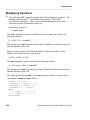
Multiplying Operators
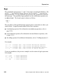
Sign
Adding Operators
Shift Operators
Relational Operators
Predefined Equality and Inequality Operators
Predefined Ordering Operators
Logical Operators
Static Expressions
Universal Expressions
2-13
2-16
2-17
2-18
2-20
2-22
2-23
2-28
2-28
2-29
2-30
2-31
2-32
2-36
Section 3
Naming, Scope, and Visibility
Naming
Simple Names
Selected Names
Indexed Names
Slice Names
Attribute Names
Scope and Visibility
Declarative Region
Scope
Scope Rules
Visibility
Visibility Rules
use_clause
Overload Resolution
iv
3-1
3-3
3-4
3-4
3-8
3-9
3-10
3-12
3-12
3-13
3-15
3-16
3-17
3-22
3-24
Mentor Graphics VHDL Reference Manual, July 1994
Table of Contents
________________________________________________________________________________________________________________________
TABLE OF CONTENTS [continued]
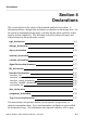
Section 4
Declarations
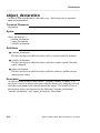
type_declaration
subtype_declaration
object_declaration
constant_declaration
variable_declaration
Signal Declaration Summary
file_declaration
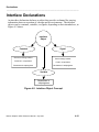
Interface Declarations
interface_list
interface_constant_declaration
interface_signal_declaration
interface_variable_declaration
association_list
alias_declaration
component_declaration
Type Conversion Functions
4-1
4-4
4-7
4-10
4-13
4-15
4-17
4-18
4-21
4-22
4-24
4-26
4-29
4-31
4-35
4-36
4-37
Section 5
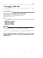
Types
scalar_type_definition
range_constraint
integer_type_definition
Predefined Integer Types
floating_type_definition
Predefined Floating Point Types
physical_type_definition
Predefined Physical Types
enumeration_type_definition
Predefined Enumeration Types
composite_type_definition
Mentor Graphics VHDL Reference Manual, July 1994
5-1
5-4
5-5
5-9
5-11
5-12
5-14
5-15
5-18
5-19
5-21
5-22
v
Table of Contents
________________________________________________________________________________________________________________________
TABLE OF CONTENTS [continued]
Section 5 Types [continued]
array_type_definition
Summary of Array Type Rules
Array Operations
record_type_definition
access_type_definition
Incomplete Types
file_type_definition
5-22
5-27
5-28
5-29
5-31
5-32
5-34
Section 6
6-1
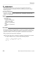
Statements
Statement Classes
sequential_statement
concurrent_statement
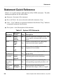
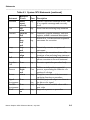
Statement Quick Reference
assertion_statement
block_statement
case_statement
component_instantiation_statement
concurrent_assertion_statement
concurrent_procedure_call
concurrent_signal_assignment_stmnt
conditional_signal_assignment
selected_signal_assignment
exit_statement
generate_statement
if_statement
loop_statement
next_statement
null_statement
procedure_call_statement
process_statement
return_statement
vi
6-2
6-5
6-7
6-8
6-10
6-12
6-15
6-17
6-19
6-21
6-23
6-25
6-27
6-28
6-30
6-34
6-36
6-38
6-39
6-40
6-41
6-44
Mentor Graphics VHDL Reference Manual, July 1994
Table of Contents
________________________________________________________________________________________________________________________
TABLE OF CONTENTS [continued]
Section 6 Statements [continued]
signal_assignment_statement
variable_assignment_statement
wait_statement
6-46
6-48
6-49
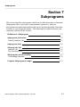
Section 7
Subprograms
Definition of a Subprogram
subprogram_declaration
formal_parameter_list
subprogram_body
Subprogram Calls
function_call
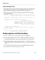
The Procedure Call
Subprograms and Overloading
Overloading Operators
Rules for Operator Overloading
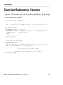
Complete Subprogram Example
7-1
7-3
7-6
7-8
7-10
7-13
7-15
7-17
7-17
7-18
7-18
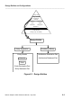
7-19
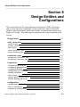
Section 8
Design Entities and Configurations
8-1
Design Entities
entity_declaration
entity_header
generic_clause
port_clause
entity_declarative_part
entity_statement_part
architecture_body
architecture_declarative_part
8-2
8-4
8-6
8-7
8-8
8-10
8-12
8-14
8-17
Mentor Graphics VHDL Reference Manual, July 1994
vii
Table of Contents
________________________________________________________________________________________________________________________
TABLE OF CONTENTS [continued]
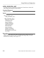
Section 8 Design Entities and Configurations [continued]
architecture_statement_part
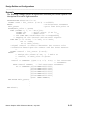
Components
Component Declarations
Component Instantiations
Component Binding
configuration_specification
binding_indication
entity_aspect
Generic and Port Map Aspects
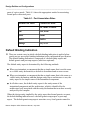
Default Binding Indication
Configurations
configuration_declaration
block_configuration
component_configuration
8-18
8-20
8-21
8-22
8-23
8-25
8-29
8-31
8-32
8-33
8-34
8-35
8-39
8-43
Section 9
9-1
Design Units and Packages
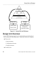
Design Unit Overview
context_clause
library_clause
Example of a Design Library
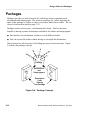
Packages
package_declaration
package_body
Predefined Packages
Package Standard
std_logic_1164
std_logic_1164_ext
Package Textio
Mentor Graphics Predefined Packages
std.math
mgc_portable.qsim_logic
viii
9-2
9-5
9-8
9-10
9-12
9-13
9-15
9-18
9-18
9-21
9-26
9-30
9-33
9-34
9-36
Mentor Graphics VHDL Reference Manual, July 1994
Table of Contents
________________________________________________________________________________________________________________________
TABLE OF CONTENTS [continued]
Section 9 Design Units and Packages [continued]
mgc_portable.qsim_relations
9-47
Section 10
Attributes
Attribute Overview
attribute_name
Predefined Attributes
Detailed Predefined Attribute Description
Array Object Attributes
’high[(n)]
’left[(n)]
’length[(n)]
’low[(n)]
’range[(n)]
’reverse_range[(n)]
’right[(n)]
Block Attributes
’behavior
’structure
Signal Attributes
’active
’delayed[(t)]
’event
’last_active
’last_event
’last_value
’quiet[(t)]
’stable[(t)]
’transaction
Signal Attribute Example
Type Attributes
’base
Mentor Graphics VHDL Reference Manual, July 1994
10-1
10-1
10-3
10-5
10-7
10-8
10-11
10-13
10-15
10-17
10-19
10-21
10-23
10-24
10-25
10-26
10-28
10-29
10-30
10-31
10-32
10-33
10-34
10-35
10-36
10-37
10-38
10-40
10-42
ix
Table of Contents
________________________________________________________________________________________________________________________
TABLE OF CONTENTS [continued]
Section 10 Attributes [continued]
’high
’left
’leftof(x)
’low
’pos(x)
’pred(x)
’right
’rightof(x)
’succ(x)
’val(x)
User-Defined Attributes
attribute_declaration
attribute_specification
10-43
10-44
10-45
10-46
10-47
10-48
10-49
10-50
10-51
10-52
10-53
10-54
10-55
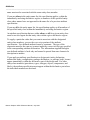
Section 11
11-1
Signals
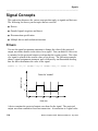
Signal Concepts
Drivers
Guarded Signals
disconnection_specification
Multiple Drivers and Resolution Functions
signal_declaration
Default Expression
Signal Assignments
Sequential Signal Assignments
Concurrent Signal Assignments
Delay Concepts
Delta Delay
x
11-4
11-4
11-5
11-8
11-10
11-14
11-15
11-16
11-16
11-17
11-19
11-20
Mentor Graphics VHDL Reference Manual, July 1994
Table of Contents
________________________________________________________________________________________________________________________
TABLE OF CONTENTS [continued]
Appendix A
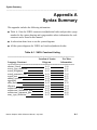
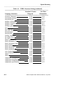
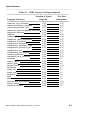
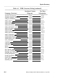
Syntax Summary
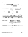
How to Read a Syntax Diagram
A-1
A-9
Appendix B
Locating Language Constructs
B-1
Index
Mentor Graphics VHDL Reference Manual, July 1994
xi
Table of Contents
________________________________________________________________________________________________________________________
LIST OF FIGURES
1-1. Lexical Elements
1-2. Lexical Element Use
1-3. Special Characters Syntax
2-1. Expressions
2-2. Expression Concept
3-1. Naming, Scope, and Visibility
3-2. Slice Name Concept
3-3. Scope
3-4. Scope of Entity Plus Architecture
3-5. Visibility
3-6. Declaration Hiding and Homographs
3-7. No Homograph Instance
3-8. Multiple Use Clauses
4-1. Declarations
4-2. Interface Object Concept
4-3. Association List Concept
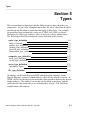
5-1. Types
5-2. Range Constraints in Subtype Indications
5-3. Unconstrained Arrays
6-1. Statements
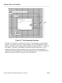
7-1. Subprograms
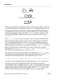
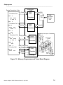
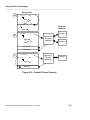
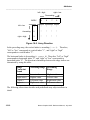
7-2. Memory Programmer and Tester Block Diagram
8-1. Design Entities
8-2. Components
9-1. Design Units and Packages
9-2. Context Clause Concept
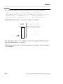
9-3. Input Buffer Schematic
9-4. Package Concept
10-1. Attributes
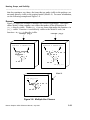
10-2. Array Direction
10-3. Signal Attribute Concept
10-4. Example of All The Signal Attributes
11-1. Signals
11-2. Composition of a Signal
11-3. Resolution Function Concept
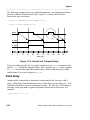
11-4. Inertial and Transport Delay
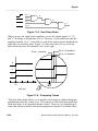
11-5. Zero Delay Gates
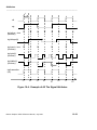
11-6. Comparing Traces
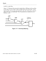
11-7. Unit-delay Modeling
xii
1-2
1-4
1-5
2-2
2-3
3-2
3-9
3-14
3-15
3-17
3-20
3-21
3-23
4-2
4-21
4-32
5-3
5-7
5-27
6-4
7-2
7-5
8-3
8-20
9-2
9-7
9-10
9-12
10-2
10-10
10-28
10-39
11-2
11-3
11-11
11-20
11-22
11-22
11-23
Mentor Graphics VHDL Reference Manual, July 1994
Table of Contents
________________________________________________________________________________________________________________________
LIST OF FIGURES [continued]
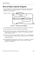
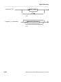
A-1. Example Syntax Diagram
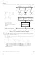
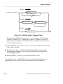
A-2. Multiple Syntax Diagram Paths
Mentor Graphics VHDL Reference Manual, July 1994
A-9
A-10
xiii
Table of Contents
________________________________________________________________________________________________________________________
LIST OF TABLES
1-1. Replacement Characters
1-2. VHDL Reserved Words
2-1. Type Conversions
2-2. Operators by Precedence
2-3. Miscellaneous Operators
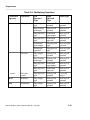
2-4. Multiplying Operators
2-5. Adding Operators
2-6. VHDL Relational Operators
2-7. Local Static Operands
2-8. Global Static Operands
2-9. Universal Expression Operators
3-1. Immediate Scope Exceptions
3-2. Visibility by Selection
4-1. Objects
6-1. System-1076 Statements
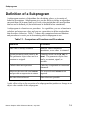
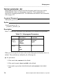
7-1. Comparison of Functions and Procedures
7-2. Subprogram Parameters
8-1. Port Association Rules
10-1. Attributes
11-1. Driver Resolution Table
A-1. VHDL Construct Listing
xiv
1-7
1-9
2-12
2-17
2-18
2-21
2-23
2-29
2-33
2-35
2-36
3-16
3-19
4-12
6-8
7-3
7-8
8-33
10-6
11-12
A-1
Mentor Graphics VHDL Reference Manual, July 1994
About This Manual
________________________________________________________________________________________________________________________
About This Manual
This manual contains reference material for the VHDL* language defined in
IEEE Std 1076-1987, IEEE Standard VHDL Language Reference Manual.
Mentor Graphics has several product offerings based on VHDL that allow
system and component designers to create and analyze language models of their
systems and integrated circuits.
Manual Organization
●
Section 1, "Lexical Elements," describes the most basic items that you use to
form the VHDL language.
●
Section 2, "Expressions," describes the items you use to create formulas for
computing values and the operators you use in these formulas.
●
Section 3, "Naming, Scope, and Visibility," describes how to identify items,
and the region of code in which the item has effect.
●
Section 4, "Declarations," describes how to define a design item.
●
Section 5, "Types," describes how to specify the kind of a defined design
item.
●
Section 6, "Statements," describes all the concurrent and sequential statements
you can use to specify different actions.
●
Section 7, "Subprograms," describes the procedure and the function which
allow you to partition descriptions into stand-alone modules.
●
Section 8, "Design Entities and Configurations," discusses the major hardware
abstraction in VHDL, the design entity, and it describes how components are
bound together to make a complete design.
___________________
*VHDL stands for VHSIC (Very High Speed Integrated Circuit) Hardware
Description Language.
Mentor Graphics VHDL Reference Manual, July 1994
xv
About This Manual
________________________________________________________________________________________________________________________
●
Section 9, "Design Units and Packages," describes stand-alone descriptions
that you can place into a library and storage facilities for collecting commonly
used declarations and subprograms.
●
Section 10, "Attributes," describes the items you use to create your own
attributes and describes the predefined attributes.
●
Section 11, "Signals," describes the items you use to communicate between
design entities.
●
Appendix A, "Syntax Summary," shows every language construct in the form
of syntax diagrams arranged in alphabetical order. Each diagram has a
reference to the appropriate page in this manual to refer to for more
information.
●
Appendix B, "Locating Language Constructs," shows how to quickly locate
where you can use particular VHDL language constructs.
Using This Manual
This manual presents the VHDL language in a reference format. Each major
topic of VHDL is contained in its own section, allowing you look up the topics at
random. Throughout the manual there are references to other locations where
you can find more detailed information on a particular topic.
This manual documents the language defined in IEEE Std 1076-1987, IEEE
Standard VHDL Language Reference Manual, not a particular Mentor Graphics
implementation of this language.
S System-1076 readers should watch for paragraphs or sentences in this manual
that are preceded by an S (like the one preceding this paragraph). System-1076
users who see an S beside a topic should consult Appendix C of the System-1076
Design and Model Development Manual. Readers who use the Bold Browser can
click on the S character to bring up the appropriate page in that manual.
Hardcopy readers can find information in that manual by using the table of
contents. Appendix C in the System-1076 Design and Model Development
Manual, which is organized with the same section and subsection names as this
manual, contains important additional information on the marked topic.
E When a paragraph is preceded by an E, Explorer VHDLsim readers should
xvi
Mentor Graphics VHDL Reference Manual, July 1994
About This Manual
________________________________________________________________________________________________________________________
consult the Explorer VHDLsim User’s Manual (Appendix A) for further
information on the marked topic.
For quick access to information you should look up a topic in the index of this
manual. If you are interested in a certain language construct, consult Appendix
A. This appendix contains every language construct in alphabetical order. Each
construct shows a page reference for more information on this subject.
The basic structure of this manual is to present an overview of a concept,
followed by the related BNF description and an example of the topic. Finally, all
the rules and further information about the topic are discussed.
This manual is designed to be the companion to the Mentor Graphics
Introduction to VHDL. The introduction manual covers the major topics of
VHDL in an overview method, without going into all the rules on a given
construct. Therefore, there is an overlap of information between these two
manuals.
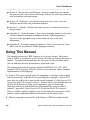
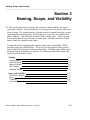
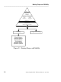
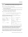
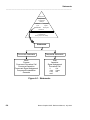
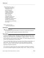
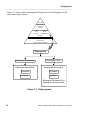
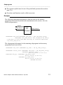
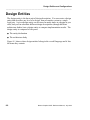
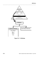
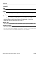
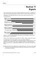
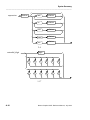
To tie all the sections of this manual into the language as a whole, a pyramid,
such as the one shown in the following illustration, appears at the beginning of
each section. This illustration shows you where in the language the topic of a
given section belongs and gives some details about the section topic.
Mentor Graphics VHDL Reference Manual, July 1994
xvii
About This Manual
________________________________________________________________________________________________________________________
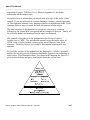
Notational Conventions
This subsection describes the conventions used throughout this manual for
language syntax and the graphical syntax diagrams.
For information about general documentation conventions, refer to Mentor
Graphics Documentation Conventions.
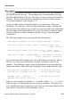
item
A syntax-diagram item shown in boldface text is a reserved word.
For example, entity and is in the following BNF description are
reserved words. Also see the subsection titled "BNF Syntax
Description Method" on page xix.
entity entity_simple_name is
entity_header
entity_declarative_part
[ begin
entity_statement_part ]
end [ entity_simple_name ] ;
item
A lowercase, monospaced item in a program example is a
user-specified item. (See the following code example). This font is
also used in text when referring to specific items from a program
example such as the name counter_circuit in the following code
example.
ITEM
An uppercase, monospaced code item in a program example is a
reserved word. In the following example, ENTITY and IS are
reserved words:
ENTITY counter_circuit IS
PORT (a: IN bit_vector(0 TO 3);
c: OUT bit_vector(0 TO 1));
END counter_circuit;
prefix_item The italic prefix preceding an item provides supplemental
information on the construct "item". prefix_item is not considered a
language construct. For example, time_expression indicates a
construct called "expression" that is used for expressing time.
xviii
Mentor Graphics VHDL Reference Manual, July 1994
About This Manual
________________________________________________________________________________________________________________________
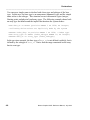
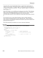
BNF Syntax Description Method
BNF (Backus-Naur Format) is another method used in this manual to describe
the syntax of the VHDL language. The following example shows a BNF method
of showing the syntax of a given construct:
example_construct ::=
construct_one { , construct_one}
| construct_two [ construct_three ]
| reserved_word
Certain characters represent specific meaning when reading the BNF syntax
description.
●
::= The ::= combination of characters on the first line of the BNF description
separates the subject (such as example_construct) from the description.
●
regular text - Text that is not set off with brackets [] or braces {} indicates
that the item is required.
●
[ construct_three ] - Text surrounded by square brackets [] denotes an
optional area that can be used only once. In this example, construct_three is
not required in the example_construct syntax. If construct_three is used
along with construct_two, it can be used only once.
●
{ , construct_one } - Text surrounded by braces {} denotes an optional area
that can be used one or more times.
●
construct_one - Italic text within a construct name indicates additional
information and does not represent an actual language construct. The words
that follow the italics represent an actual language construct.
●
boldface text - This convention sets off reserved words and characters that
must be typed literally as presented.
●
| - A vertical bar indicates an "or" situation. Thus, line1 | line2 | line3
indicates that either line1 or line2 or line3 can be used to describe the syntax.
Mentor Graphics VHDL Reference Manual, July 1994
xix
About This Manual
________________________________________________________________________________________________________________________
Related Publications
The following Mentor Graphics manuals contain important information on
related topics. The list is divided into three parts: one for all Mentor Graphics
VHDL users, one specifically for Explorer VHDLsim users, and one
specifically for System-1076 users.
In addition to this manual, the following manual relates to all Mentor Graphics
VHDL solutions:
●
Mentor Graphics VHDL Reference Manual (this manual) contains reference
information for the language and related packages.
●
Mentor Graphics Introduction to VHDL contains fundamental VHDL
concepts.
The following manuals pertain to Explorer VHDLsim users:
●
Explorer VHDLsim Quick Reference Booklet provides reference information
for Explorer VHDLsim in a quick-lookp format.
●
Explorer VHDLsim User’s and Reference Manual contains task-oriented
operating instructions for Explorer VHDLsim, covering such topics as
compiling and simulating VHDL models in the Explorer VHDLsim
environment.
●
Explorer Lsim User’s Manual describes and explains how to use the Explorer
Lsim Mixed-Signal, Multi-Level Simulator. Since VHDLsim is an integral
part of the Lsim simulation environment, you will need to refer to this manual
while using Explorer VHDLsim.
●
Explorer Lsim Reference Manual describes Explorer Lsim Simulator
commands, menus, and programs.
●
M Language User’s Guide describes how to use the M hardware description
language.
The following manuals pertain to System-1076 users:
●
xx
Getting Started with System-1076 contains information about creating,
modeling, and debugging hardware designs with Mentor Graphics
Mentor Graphics VHDL Reference Manual, July 1994
About This Manual
________________________________________________________________________________________________________________________
System-1076. System-1076 allows system and component designers to create
language models of their systems or chips. System-1076 is based on IEEE
Std 1076-1987, IEEE Standard VHDL Language Reference Manual.
●
System-1076 Design and Model Development Manual provides concepts,
procedures, and techniques for using VHDL within the System-1076
environment.
●
System-1076 Error Message Manual contains information about the error and
warning messages generated when compiling and simulating System-1076
models.
●
AutoLogic VHDL Reference Manual defines the syntax of VHDL constructs
used for logic synthesis and describes their resultant implementations after
synthesis by AutoLogic VHDL.
●
AutoLogic VHDL Synthesis Guide describes using VHDL within the
synthesis environment, the coding guidelines for writing VHDL code that can
be synthesized, and the operating procedures for running AutoLogic VHDL.
●
BOLD Browser User’s Manual describes the BOLD Browser and covers
basic operations such as locating and viewing online information.
●
Design Architect Reference Manual contains information about the functions
used to create and modify schematic and cabling designs, logic symbols, and
VHDL source files.
●
Design Architect User’s Manual provides a basic overview of Design
Architect; key concepts for using the Schematic Editor, Symbol Editor, and
VHDL Editor; and design creation procedures.
●
Digital Modeling Guide contains basic information for designers and
modelers using the Mentor Graphics digital analysis environment. This
manual can help you make some rudimentary decisions in model or design
development.
●
Digital Simulators Reference Manual contains information about the
commands, functions, userware, and related reference material specific to the
Mentor Graphics digital analysis applications.
Mentor Graphics VHDL Reference Manual, July 1994
xxi
About This Manual
________________________________________________________________________________________________________________________
●
Getting Started with Design Architect Training Workbook is for new users of
Design Architect who have some knowledge about schematic drawing and
electronic design and are familiar with the UNIX or Aegis environment. This
training workbook provides basic instructions on using Design Architect to
create schematics and symbols.
●
Getting Started with Falcon Framework Training Workbook is for new users
of the Mentor Graphics Falcon Framework. This workbook introduces you to
the components of the Falcon Framework and provides information about and
practice using the Common User Interface, Design Manager, INFORM,
Notepad, and Decision Support System applications.
●
Getting Started with QuickSimII Training Workbook is for Electrical
Engineers who have not previously used QuickSimII. This training
workbook provides basic instructions on using QuickSimII to simulate digital
designs.
●
Simview Common Simulation User’s Manual contains information about the
features common to the Mentor Graphics analog and digital analysis
applications.
●
Simview Common Simulation Reference Manual contains reference
information about the commands, functions, userware, and features common
to the Mentor Graphics analog and digital analysis applications.
●
Notepad User’s and Reference Manual describes how to edit files and
documents in Notepad, a text editor. This manual provides examples,
explanations, and an alphabetical listing of AMPLE functions that are
available for customizing Notepad.
●
QuickSim II User’s Manual describes how to use the QuickSim II logic
simulator. This manual provides background information, a hands-on tutorial
intended for new users, various simulation procedures, and a comprehensive
list of related procedures.
xxii
Mentor Graphics VHDL Reference Manual, July 1994
Lexical Elements
________________________________________________________________________________________________________________________
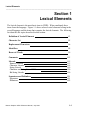
Section 1
Lexical Elements
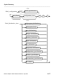
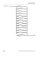
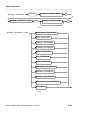
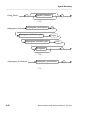
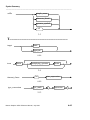
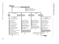
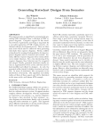
The lexical element is the most basic item in VHDL. When combined, these
items form the language. Figure 1-1 shows where lexical elements belong in the
overall language and the items that comprise the lexical elements. The following
list identifies the topics described in this section:
Definition of Lexical Elements
1-3
Character Set
1-5
Replacement Characters
1-6
Identifiers
1-8
Reserved Words
1-9
Comments
1-15
Literals
Numeric Literals
Character Literals
String Literals
Character and String Literal Differences
Bit String Literals
1-15
1-15
1-18
1-19
1-20
1-20
Separators and Delimiters
Separators
Delimiters
1-21
1-21
1-22
Mentor Graphics VHDL Reference Manual, July 1994
1-1
Lexical Elements
________________________________________________________________________________________________________________________
Design Units
Design Entities
Configurations
Packages
Attributes
Components
Types
Signals
Statements
Subprograms
Declarations
Expressions
Lexical Elements
Naming, Scope, and Visibility
Character
Set
Lexical Elements
Identifier
Comment
Literal
Delimiter
Numeric
Character
String
Figure 1-1. Lexical Elements
1-2
Mentor Graphics VHDL Reference Manual, July 1994
Lexical Elements
________________________________________________________________________________________________________________________
Definition of Lexical Elements
Lexical elements are the items used to form the VHDL language. A lexical
element is one of the following:
●
An identifier (or a reserved word)
●
A comment
●
A literal
●
❍
Numeric
❍
Character
❍
String
A delimiter
VHDL has a character set that contains 95 printable characters. From this
character set, lexical elements are formed. Lexical elements, in turn, form the
language constructs that are the building blocks of VHDL. For a complete
summary of all the language constructs, see the syntax summary appendix
starting on page A-1.
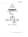
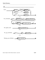
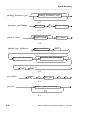
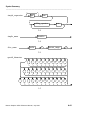
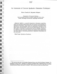
You combine the language constructs to create design units, which are a group of
specific language constructs that can be compiled independently and placed in a
design library. For information on design units, refer to page 9-1.
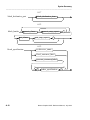
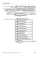
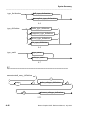
Finally, you put the design units together to form the VHDL code description of
your design. Figure 1-2 shows how lexical elements fit into the coding process.
Mentor Graphics VHDL Reference Manual, July 1994
1-3
Lexical Elements
________________________________________________________________________________________________________________________
Character Set
Lexical Elements
Language Constructs
Design Units
Code
Figure 1-2. Lexical Element Use
1-4
Mentor Graphics VHDL Reference Manual, July 1994
Lexical Elements
________________________________________________________________________________________________________________________
Character Set
Before you can use the lexical elements, you must know the character set
allowed in VHDL. There are 95 printable ASCII graphic characters, and 5
format effectors that you can use in VHDL.
The graphic characters consist of the following:
●
letter: uppercase
ABCDEFGHIJKLMNOPQRSTUVWXYZ
lowercase
abcdefghijklmnopqrstuvwxyz
●
digit:
0123456789
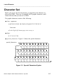
●
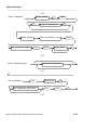
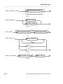
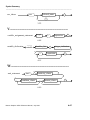
special_characters: Figure 1-3 shows the special characters.
special_characters
^
’
(
)
+
-
=
@
#
&
*
!
‘
{
}
<
>
_
,
.
;
:
\
/
[
]
$
%
|
~
"
?
Figure 1-3. Special Characters Syntax
Mentor Graphics VHDL Reference Manual, July 1994
1-5
Lexical Elements
________________________________________________________________________________________________________________________
There are five format effectors used in VHDL. A format effector is a
non-printable control character you use to format the ASCII text in your source
file. The following list shows the VHDL format effectors:
●
Tab
●
Vertical tab
●
Carriage return
●
Line feed
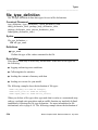
●
Form feed
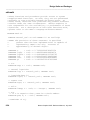
Replacement Characters
You may wish to port to a system that does not use the following special
characters:
●
Vertical bar (|)
●
Number sign (#)
●
Double quote (")
In this situation, there are replacement characters available that do not alter a
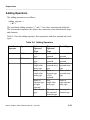
description. Table 1-1 lists the replacement information. Following Table 1-1
are replacement examples.
1-6
Mentor Graphics VHDL Reference Manual, July 1994
Lexical Elements
________________________________________________________________________________________________________________________
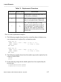
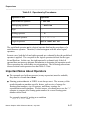
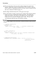
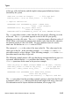
Table 1-1. Replacement Characters
Character Replacement
Restrictions
|
!
Replacement is allowed only if the ! is
to be used as a delimiter.
#
:
The # of based literals is replaced by :
only if you replace both # characters.
"
%
The " used on both ends of string
literals can be replaced by % only if
each embedded " is replaced with %
using the same rules for embedded ".
Replacement is allowed for bit string
literals also.
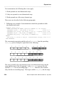
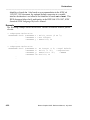
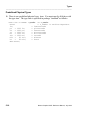
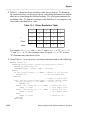
Here are some replacement examples:
1. The following example shows how the vertical-bar choice delimiters in a
case statement can be replaced by exclamation points.
CASE test IS
WHEN store | save | keep
WHEN OTHERS
END CASE;
=> acc := ’1’;
=> illop := true;
CASE test IS
WHEN store ! save ! keep
WHEN OTHERS
END CASE;
=> acc := ’1’;
=> illop := true;
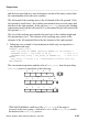
2. The following example shows how the number sign can be replaced by the
colon in a based literal.
16#1f#
16:1f:
3. In the following string literals, double quotes have been replaced by the
percent sign.
"lights""will""turn green"
%lights%%will%%turn green%
Mentor Graphics VHDL Reference Manual, July 1994
1-7
Lexical Elements
________________________________________________________________________________________________________________________
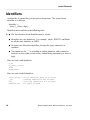
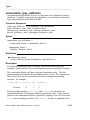
Identifiers
An identifier is a name that you assign to a design item. The syntax for an
identifier is as follows:
identifier ::=
letter {[_] letter | digit}
Identifiers must conform to the following rules:
S ● The first character of an identifier must be a letter.
●
Identifiers are case-insensitive. For example: ident1, IDENT1, and Ident1
are all the same identifier in VHDL.
●
No spaces are allowed in identifiers, because the space character is a
separator.
●
You cannot use the "_" as a leading or trailing character, and it cannot be
used two or more times in succession, without being separated by a letter or
digit.
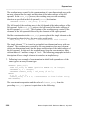
Here are some valid identifiers:
d_FF
my_Test_circuit
R169
ExampleOut
Here are some invalid identifiers:
2test_design
_jrb
R14_
Example Out
1-8
--first character must be a letter
--leading underscore not allowed
--trailing underscore not allowed
--no space allowed
Mentor Graphics VHDL Reference Manual, July 1994
Lexical Elements
________________________________________________________________________________________________________________________
Reserved Words
S Reserved words have specific meaning to VHDL; therefore, you cannot use a
reserved word as an identifier. For example, you are not allowed to declare a
variable name "all", as the following example does, because all is a reserved
word.
VARIABLE all: integer;
-- "all" is an illegal identifier
Even if you use "All" (with a capital A), you still get an error; the case of the
letters does not differentiate a name you declare from a reserved word, if it is the
same word.
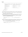
There are two exceptions to the rules involving reserved words. First, the
reserved word range is also the identifier for the predefined attribute ’range[(N)].
For more information on this predefined attribute, refer to page 10-19. Second,
you can use reserved words in comments and string literals, where they are not
considered reserved words. For example, the use of the word "all" as part of the
comment in the preceding example is perfectly legal.
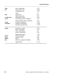
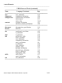
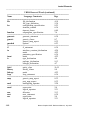
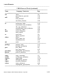
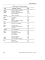
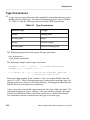
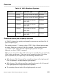
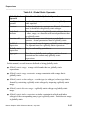
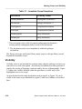
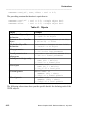
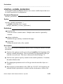
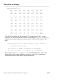
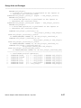
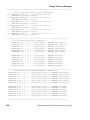
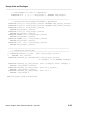
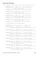
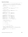
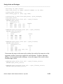
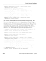
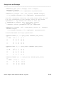
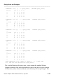
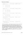
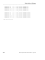
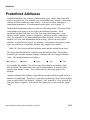
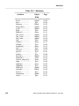
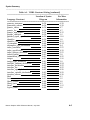
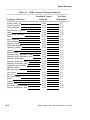
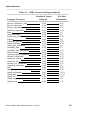
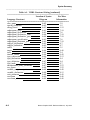
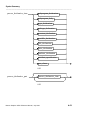
Table 1-2 lists the VHDL reserved words. The heading descriptions for Table
1-2 are as follows:
●
Name: the name of the reserved word.
●
Language Constructs: the language constructs that use the reserved word.
●
Page: the page in this manual where the reserved word is used in the context
of the listed language construct.
Table 1-2. VHDL Reserved Words
---------------------------------------------------------------------------------------------Name
Language Constructs
Page
=======================================================
abs
miscellaneous_operator
2-18
factor
2-4
access
access_type_definition
5-31
after
disconnection_specification
11-8
waveform_element
6-46
Mentor Graphics VHDL Reference Manual, July 1994
1-9
Lexical Elements
________________________________________________________________________________________________________________________
alias
all
alias_declaration
4-35
entity_name_list
10-55
instantiation_list
8-25
suffix
3-5
and
expression
2-4
logical_operator
2-31
architecture
architecture_body
8-14
array
constrained_array_definition
5-23
unconstrained_array_definition
5-23
assert
assertion_statement
6-10
attribute
attribute_declaration
10-54
attribute_specification
10-55
---------------------------------------------------------------------------------------------begin
architecture_body
8-14
block_statement
6-12
entity_declaration
8-4
process_statement
6-41
subprogram_body
7-10
block
block_statement
6-12
body
package_body
9-15
buffer
mode
4-22
bus
interface_signal_declaration
4-26
signal_kind
11-14
----------------------------------------------------------------------------------------------
1-10
Mentor Graphics VHDL Reference Manual, July 1994
Lexical Elements
________________________________________________________________________________________________________________________
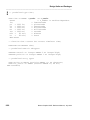
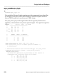
VHDL Reserved Words [continued]
---------------------------------------------------------------------------------------------Name
Language Constructs
Page
=======================================================
case
case_statement
6-15
component
component_declaration
4-36
configuration
configuration_declaration
8-35
entity_aspect
8-31
entity_class
10-55
constant
constant_declaration
4-13
interface_constant_declaration
4-24
---------------------------------------------------------------------------------------------disconnect
disconnection_specification
11-8
downto
direction
5-5
---------------------------------------------------------------------------------------------else
conditional_waveforms
6-25
if_statement
6-34
elsif
if_statement
6-34
end
architecture_body
8-14
block_statement
6-12
case_statement
6-15
component_declaration
4-36
entity_declaration
8-4
if_statement
6-34
loop_statement
6-36
package_body
9-15
package_declaration
9-13
physical_type_definition
5-15
process_statement
6-41
subprogram_body
7-10
entity
entity_aspect
8-31
entity_declaration
8-4
exit
exit_statement
6-28
----------------------------------------------------------------------------------------------
Mentor Graphics VHDL Reference Manual, July 1994
1-11
Lexical Elements
________________________________________________________________________________________________________________________
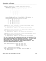
VHDL Reserved Words [continued]
---------------------------------------------------------------------------------------------Name
Language Constructs
Page
=======================================================
file
file_declaration
4-18
file_type_definition
5-34
for
configuration_specification
8-25
iteration_scheme
6-36
timeout_clause
6-49
function
subprogram_specification
7-6
---------------------------------------------------------------------------------------------generate
generate_statement
6-30
generic
generic_clause
8-7
generic_map_aspect
8-32
guarded
options
6-23
---------------------------------------------------------------------------------------------if
if_statement
6-34
in
interface_constant_declaration
4-24
mode
4-22
parameter_specification
6-36
inout
mode
4-22
is
type_declaration
4-4
package_declaration
9-13
subtype_declaration
4-7
---------------------------------------------------------------------------------------------label
entity_class
10-55
library
library_clause
9-8
linkage
mode
4-22
loop
loop_statement
6-36
---------------------------------------------------------------------------------------------map
generic_map_aspect
8-32
port_map_aspect
8-32
mod
multiplying_operator
2-20
---------------------------------------------------------------------------------------------nand
expression
2-4
logical_operator
2-31
new
allocator
2-13
next
next_statement
6-38
nor
expression
2-4
logical_operator
2-31
1-12
Mentor Graphics VHDL Reference Manual, July 1994
Lexical Elements
________________________________________________________________________________________________________________________
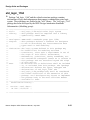
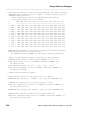
VHDL Reserved Words [continued]
---------------------------------------------------------------------------------------------Name
Language Constructs
Page
=======================================================
not
factor
2-4
miscellaneous_operator
2-18
null
literal
1-15
null_statement
6-39
waveform_element
6-46
---------------------------------------------------------------------------------------------of
architecture_body
8-14
constrained_array_definition
5-23
file_type_definition
5-34
unconstrained_array_definition
5-23
on
sensitivity_clause
6-49
open
actual_designator
4-31
entity_aspect
8-31
or
expression
2-4
logical_operator
2-31
others
choice
2-8
entity_name_list
10-55
instantiation_list
8-25
out
mode
4-22
------------------------------------------------------------------------------------------package
package_body
9-15
package_declaration
9-13
port
port_clause
8-8
port_map_aspect
8-32
procedure
subprogram_specification
7-6
process
process_statement
6-41
---------------------------------------------------------------------------------------------range
range_constraint
5-5
record
record_type_definition
5-29
register
signal_kind
11-14
rem
multiplying_operator
2-20
report
assertion_statement
6-10
return
return_statement
6-44
subprogram_specification
7-6
----------------------------------------------------------------------------------------------
Mentor Graphics VHDL Reference Manual, July 1994
1-13
Lexical Elements
________________________________________________________________________________________________________________________
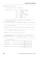
VHDL Reserved Words [continued]
---------------------------------------------------------------------------------------------Name
Language Constructs
Page
=======================================================
select
selected_signal_assignment
6-27
severity
assertion_statement
6-10
signal
interface_signal_declaration
4-26
signal_declaration
11-14
subtype
subtype_declaration
4-7
---------------------------------------------------------------------------------------------then
if_statement
6-34
to
direction
5-5
transport
options
6-23
signal_assignment_statement
6-46
type
type_declaration
4-4
---------------------------------------------------------------------------------------------units
physical_type_definition
5-15
until
condition_clause
6-49
use
configuration_specification
8-25
use_clause
3-22
---------------------------------------------------------------------------------------------variable
variable_declaration
4-15
---------------------------------------------------------------------------------------------wait
wait_statement
6-49
when
conditional_waveforms
6-25
exit_statement
6-28
next_statement
6-38
selected_waveforms
6-27
while
iteration_scheme
6-36
with
selected_signal_assignment
6-27
---------------------------------------------------------------------------------------------xor
expression
2-4
logical_operator
2-31
----------------------------------------------------------------------------------------------
1-14
Mentor Graphics VHDL Reference Manual, July 1994
Lexical Elements
________________________________________________________________________________________________________________________
Comments
You can include comments to document your VHDL code. Comments consist of
two adjacent hyphens (--) followed by the text of the comment. Comments
terminate at the end of the line. For example:
-- This is the beginning of the code
counter: PROCESS (clk) -- Counter executes when clk changes
A comment can appear anywhere in a description without affecting how the code
is processed or simulated. Any of the 95 ASCII graphic characters can be used in
a comment.
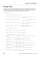
Literals
Literals are lexical elements, such as numbers, characters, and strings, that
represent themselves. VHDL has five types of literals, as shown in the following
BNF syntax description:
literal ::=
numeric_literal
| enumeration_literal
| string_literal
| bit_string_literal
| null
The following pages discuss numeric, string, and bit string literals. For
information about the enumeration literal, refer to page 5-19. The null literal
represents the null access value for an access type; it is an access value that
points to nothing. For information on access types, refer to page 5-31 .
Numeric Literals
A numeric literal represents an exact integer or real value. Examples of numeric
literals start on page 1-17. Here is the BNF description for a numeric literal:
numeric_literal ::=
abstract_literal
| physical_literal
Mentor Graphics VHDL Reference Manual, July 1994
1-15
Lexical Elements
________________________________________________________________________________________________________________________
A physical literal is used in a secondary unit declaration, as part of a physical
type definition. For more information on physical type definitions, refer to the
subsection called "physical_type_definition" in Section 5. Here is the BNF
description for a physical literal.
physical_literal ::=
[ abstract_literal ] unit_name
Abstract literals are either integer literals or real literals. You specify integer
literals and real literals either in decimal notation (decimal literal) or using
another base (based literal). A real literal includes a decimal point and is of the
type universal_real. An integer literal does not include a decimal point and is of
the type universal_integer. For information about types, refer to Section 5. The
BNF description for an abstract literal is as follows:
abstract_literal ::=
decimal_literal
| based_literal
You can think of type universal_integer as an anonymous type with no bounds,
representing all the integers in the universe. Integer literals are members of this
type. Type universal_real is also an anonymous type, with no bounds, that
represents real numbers with infinite precision. Real literals are members of this
type. Anonymous types have no name, so you cannot refer to them. Therefore,
throughout this manual universal_integer and universal_real appear in italic font
to designate that you cannot actually use these types.
A decimal literal is expressed in base 10, the conventional decimal notation. The
BNF descriptions for the decimal literal and related constructs are as follows:
decimal_literal ::=
integer [ . integer] [exponent]
integer ::=
digit {[_] digit}
exponent ::=
E[+] integer | e[+] integer | E - integer | e - integer
An integer literal cannot contain a decimal point, but it can have an exponent.
The character "E" represents an exponent and can be either uppercase or
1-16
Mentor Graphics VHDL Reference Manual, July 1994
Lexical Elements
________________________________________________________________________________________________________________________
lowercase. The "+" is optional after the "E". A space between the "E" and the
integer is not allowed. An integer literal can have a leading zero or a zero
exponent, but not a negative exponent. Spaces are not allowed. Here are some
examples of valid and invalid integer literals:
01468
17E0
769 1
-- leading zero is legal
-- zero exponent is legal
-- space NOT LEGAL
The special character "_" in the syntax for integer, has no effect on the value of
the literal. This character provides a method for grouping fields. For example:
100_000_000
-- separates fields for easier reading
The following examples show valid integer literal values:
0
14e3
27E2
2e2
34e+7
91
432_198
The following examples show valid real literal values:
17.0
23.65e-10
87.1E3
7.61e+11
0.0
0.1426
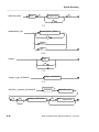
Based literals are abstract literals in which you can specify the numeric base.
The base you specify must be in the range of base 2 to base 16, inclusive. The
following diagrams shows the related syntax for a based literal.
based_literal ::=
base # based_integer [. based_integer] # [exponent]
base ::=
integer
based_integer ::=
extended_digit {[_] extended_digit}
extended_digit ::=
digit | A | B | C | D | E | F | a | b | c | d | e | f
The "#" character must enclose the based integer. The optional underline
character "_" in the based integer has no effect on the value of the literal. This
character is used to group digits for readability. The exponent is always base 10.
Mentor Graphics VHDL Reference Manual, July 1994
1-17
Lexical Elements
________________________________________________________________________________________________________________________
An extended digit is a hexadecimal digit. The letters A through F, in the
extended digit, represent the digits 10 through 15. These letters can be uppercase
or lowercase.
Within a based integer, the extended digits must be a value less than the base.
For example, 2#1101_A1B1# is not allowed because the base is 2. Therefore, the
extended digits "A" and "B" are illegal.
The following are examples of valid integer literals, using different bases:
2#101_0000#
-- base 2 representation of decimal 80
16#50#
-- base 16 representation of decimal 80
16#A0#
-- base 16 representation of decimal 160
2#1010_0000# -- base 2 representation of decimal 160
The following are examples of valid real literals, using different bases:
2#1.0#e3
-- base 2 representation of decimal 1000.0
16#4.2#
-- base 16 representation of decimal 4.125
Character Literals
A character literal is a single graphic character from the 95 printable ASCII
characters. You must enclose a character literal with single quote marks (’) as the
following syntax shows:
character_literal ::=
’ graphic_character ’
The following examples show some possible character literals:
’z’
’7’
’%’
’ ’
’"’
’’’
S A character literal is case-sensitive. Therefore, an ’X’ is not equal to an ’x’ and
’Z’ is not equal to ’z’.
1-18
Mentor Graphics VHDL Reference Manual, July 1994
Lexical Elements
________________________________________________________________________________________________________________________
String Literals
A string literal consists of zero or more graphic characters. String literals must
be enclosed between double quote marks ("). The following diagram shows the
syntax for a string literal:
string_literal ::=
" {graphic_character} "
When you use the double quote character within a string literal, another double
quote mark must precede it. For example, to include the string "message" within
the string literal "The string will be printed", you must use the following format:
"The string ""message"" will be printed"
Since a string literal is a lexical element, the end of the line format effector is
considered a separator. Therefore, if you wish to use a string literal that exceeds
the length of the line, you can concatenate the graphic characters. You
concatenate by using the ampersand (&) character. For example:
"If your string literal is too long, then "&
"use the concatenation character"
You can also concatenate graphic characters with nongraphic characters. There
are several nongraphical characters in package "standard" in the predefined type
character. For example, if you want to concatenate the nongraphical character
BEL with two string literals, the format is as follows:
"Concatenating string literals" &bel&
"with nongraphical characters"
A string literal is case-sensitive because strings are arrays of character literals,
which are case-sensitive. Therefore, the following strings are not equivalent:
"This string"
"this string"
Mentor Graphics VHDL Reference Manual, July 1994
--NOT EQUAL
1-19
Lexical Elements
________________________________________________________________________________________________________________________
Character and String Literal Differences
In some situations, it might appear to you that there is no difference between a
character literal and a string literal. For example:
’x’
-- the character literal x
"x"
-- the string literal x
The difference between a character literal and a string literal with only one item
is their type. A character literal is of the type character and a string literal is type
string. Therefore, you cannot mix the types when you perform operations on the
literals. For example:
VARIABLE x: character; --Declare "x" of subtype character.
x:= "a"; --Assign x the string literal "a". The types are
--not the same, therefore this code is not legal.
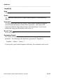
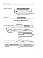
Bit String Literals
Bit string literals are strings of extended digits, enclosed by double quotes ("),
with a prefix of a base specifier. Bit string literals represent binary, octal, or
hexadecimal numbers. The following diagram shows the related syntax of the bit
string literal:
bit_string_literal ::=
base_specifier " bit_value "
base_specifier ::=
B|O|X|b|o|x
bit_value ::=
extended_digit {[_] extended_digit}
1-20
Mentor Graphics VHDL Reference Manual, July 1994
Lexical Elements
________________________________________________________________________________________________________________________
There are three valid base specifiers for bit string literals:
●
B specifies that the extended digits are restricted to the binary
number system (1 and 0).
●
O specifies that the extended digits are restricted to the octal number
system (0, 1, 2, 3, 4, 5, 6, 7).
●
X specifies that the extended digits are restricted to the hexadecimal
number system (0, 1, 2, 3, 4, 5, 6, 7, 8, 9, a, b, c, d, e, f).
The base specifiers B, O, and X can be uppercase or lowercase. You cannot
place a space between the base specifier and the bit value.
The type "bit" (from package "standard") is limited to the values of zero and one.
Therefore, the O- and X-specified literal converts to the equivalent B-specified
bit string literal. This conversion does not discard leading zeros (a leading digit
is the left-most array entry). The size of the bit string literal is the number of
digits in its binary representation.
The following examples show some possible bit string literals:
X"333"
O"333"
X"0F7"
O"72"
-- equivalent to B"001100110011"
-- equivalent to B"011011011"
-- equivalent to B"000011110111"
-- equivalent to B"111010"
Separators and Delimiters
Separators and delimiters are characters that divide and establish the boundaries
of lexical elements.
Separators
When you put lexical elements together, there are situations in which you must
use a separator between the elements. Otherwise, the adjacent lexical elements
could be construed as being a single element. There are three lexical separators:
●
Space character, except when the space is in a comment, string literal, or
character literal
Mentor Graphics VHDL Reference Manual, July 1994
1-21
Lexical Elements
________________________________________________________________________________________________________________________
●
Format effector, except when the format effector is in a comment or a string
literal
●
End of line -- consists of the line feed character
Since the end of the line is always considered a separator, all lexical elements
must appear on a single line. There must be one or more separators between an
identifier or an abstract literal and an adjacent identifier or abstract literal.
Delimiters
A delimiter is one or more special characters that establish the boundaries of one
or more lexical elements. A compound delimiter consists of two delimiters
together. The delimiters and compound delimiters you can use are as follows:
●
Delimiters: & ’ ( ) * = , - . / : ; < = > |
●
Compound delimiters: => ** :=
/=
>=
<=
<>
The delimiter characters are not delimiters when you use them in comments,
abstract literals, character literals, or string literals.
The following are examples of delimiter use:
SIGNAL yellow,green,red : bit; -- Uses "," ":" and ";"
z <= TRANSPORT t AFTER q; -- Uses the compound delimiter <=,
-- the ";" and the space
1-22
Mentor Graphics VHDL Reference Manual, July 1994
Expressions
________________________________________________________________________________________________________________________
Section 2
Expressions
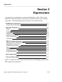
An expression is an equation or a primary that indicates a value. This section
defines the items that comprise an expression and discusses the rules for using
expressions. The following list shows the topics covered this section:
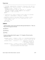
Definition of Expressions
General Expression Rules
2-3
2-4
Operands (Primaries)
Names
Literal
Aggregates
Function Calls
Qualified Expressions
Type Conversions
Allocators
2-6
2-6
2-7
2-8
2-10
2-10
2-12
2-13
VHDL Predefined Operators
Important Notes About Operators
Miscellaneous Operators
Multiplying Operators
Sign
Adding Operators
Relational Operators
Logical Operators
2-16
2-17
2-18
2-20
2-22
2-23
2-28
2-31
Static Expressions
2-32
Universal Expressions
2-36
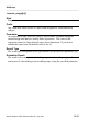
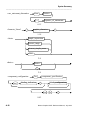
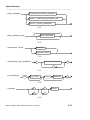
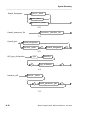
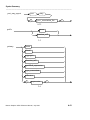
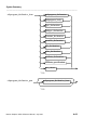
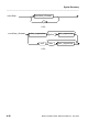
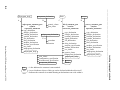
Figure 2-1 shows the where expressions fit in the overall language and the items
that comprise the expressions.
Mentor Graphics VHDL Reference Manual, July 1994
2-1
Expressions
________________________________________________________________________________________________________________________
Design Units
Design Entities
Configurations
Packages
Attributes
Components
Types
Signals
Statements
Subprograms
Declarations
Expressions
Lexical Elements
Naming, Scope, and Visibility
Expressions
Primaries
Predefined Operators
Names
Literals
Aggregates
Function Calls
Qualified Expressions
Type Conversions
(Expressions)
Miscellaneous
Multiplying
Sign
Adding
Relational
Logical
VHDL Operators
Figure 2-1. Expressions
2-2
Mentor Graphics VHDL Reference Manual, July 1994
Expressions
________________________________________________________________________________________________________________________
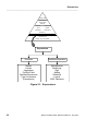
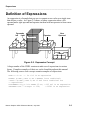
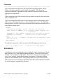
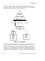
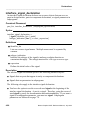
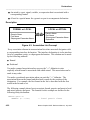
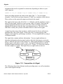
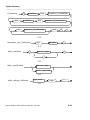
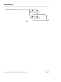
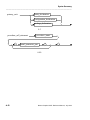
Definition of Expressions
An expression is a formula that you use to compute a new value or a single term
that defines a value. As Figure 2-2 shows, a binary expression takes a left
operand and a right operand and operates on them with an operator to form a new
operand.
Operands
right
left
1
2
Operation
1
Operator
+
New
Operand
2
3
Figure 2-2. Expression Concept
A large number of the VHDL constructs make use of expressions in various
forms. Complete examples of their use can be found throughout this manual.
The following source-code excerpts contain examples of expressions.
CASE a > b IS
-- "a > b" is an expression
ASSERT (x AND y AND z) OR r REPORT "race condition";
--Both "(x AND y AND z) OR r" and "race condition" are
-- expressions.
DISCONNECT sig_a: bit AFTER 25 ns; --"25 ns" is an expression.
VARIABLE test : integer := 256;
--"256" is an expression.
Mentor Graphics VHDL Reference Manual, July 1994
2-3
Expressions
________________________________________________________________________________________________________________________
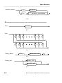
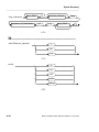
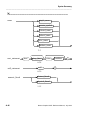
There are several related language constructs that govern the syntax of an
expression, as the following syntax descriptions show.
expression :
relation { and relation }
| relation { or relation }
| relation { xor relation }
| relation [ nand relation ]
| relation [ nor relation ]
relation :
simple_expression
[ relational_operator simple_expression ]
simple_expression :
[ sign ] term { adding_operator term }
term :
factor { multiplying_operator factor }
factor :
primary [ ** primary ]
| abs primary
| not primary
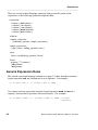
General Expression Rules
The related expression language constructs on page 2-4 show that the associative
logical operators and, or, and xor can be in a sequence. For example:
IF (a AND b AND c) /= (d AND e AND f) THEN
.
.
You cannot write an expression using the logical operators nand and nor in a
sequence, because these operators are not associative. For example:
IF (a NAND b NAND c) = (d NAND e NAND f) THEN --Illegal
--sequence
.
.
2-4
Mentor Graphics VHDL Reference Manual, July 1994
Expressions
________________________________________________________________________________________________________________________
To mix the associative logical operators, you must use parentheses. For example:
IF ((a AND b) OR c) /= ((d AND e) OR f) THEN --Mix logical
--operators
.
.
Logical operators are discussed in detail on page 2-31.
The operand types and the operator determine the expression type. The
following example shows this concept:
VARIABLE test : real := 5.0;
VARIABLE check : real := 5.5;
-- variable declarations
--
The following expression appears later in a description:
answer := test + check;
In the preceding example, the expression "test + check" is of type real because
the operand types are real.
When you use an overloaded operand, the operand type is determined by the
context in which it appears. When you use an overloaded operator, the operator
identification is also determined by the context. For more information on
overload resolution, refer to page 3-24.
If you enclose an expression in parentheses, you can use it as an operand.
Operands are described in the following subsection.
Mentor Graphics VHDL Reference Manual, July 1994
2-5
Expressions
________________________________________________________________________________________________________________________
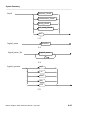
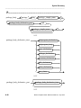
Operands (Primaries)
An operand, or primary, has a value and a type -- it is a quantity on which an
operator performs an operation. The following BNF description lists all the valid
primaries.
primary ::=
name
| literal
| aggregate
| function_call
| qualified_expression
| type_conversion
| allocator
| ( expression )
Following subsections discuss all of these items in their roles as primaries. These
items are also discussed in other sections of this manual, in relation to their other
functions within the language. Please consult the index or text references for the
locations of these discussions.
Names
When you use a name as an operand in an expression, it must be one of the
following items:
●
The name of an attribute that returns a value
●
A name that identifies an object or value
The value of a operand is the value of the object. For more information on
objects, refer to page 4-10. Names are discussed in detail beginning on page 3-3.
The following example shows the use of names in expressions:
2-6
Mentor Graphics VHDL Reference Manual, July 1994
Expressions
________________________________________________________________________________________________________________________
-- "decade", "multiplier", "freq_in", "freq_out, "x", and "z"
-- are names that identify objects; "info" identifies a type.
PROCESS
CONSTANT decade : integer := 10;
VARIABLE multiplier, freq_in, freq_out, x : integer;
TYPE info IS ARRAY (integer RANGE <>) OF integer;
VARIABLE z : info (1 TO 10);
BEGIN
-- expression for output frequency using names for operands
freq_out := (multiplier * freq_in) / decade;
--Expression using an attribute name that returns a value.
--(Right bound of array "z" is 10. Therefore "x" = 20.)
x := z’right + 10;
WAIT FOR 1 ns;
END PROCESS;
Literal
A literal consists of one or more characters that represent themselves. There are
three general categories of literals:
●
Numeric
●
Character
●
String
Literals are discussed in detail on page 1-15. Examples of literals used in
expressions follow:
VARIABLE result : integer := 1024 * 8; --Variable declaration
--with expression containing numeric literals "1024" and "8"
VARIABLE answer : character := ’x’; --Expression assigning
--character literal ’x’
-- to variable "answer"
CONSTANT string_1 : string := "011" & "true"; --Initialize
--"string_1" using an expression to concatenate
--string literals "011" and "true"
Mentor Graphics VHDL Reference Manual, July 1994
2-7
Expressions
________________________________________________________________________________________________________________________
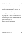
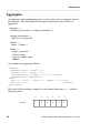
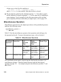
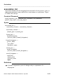
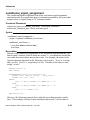
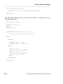
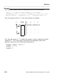
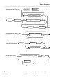
Aggregates
An aggregate is the combination of one or more values into a composite value of
an array type. The following BNF description shows the syntax related to
aggregates:
aggregate ::=
( element_association { , element_association } )
element_association ::=
[choices =>] expression
choices ::=
choice { | choice }
choice ::=
simple_expression
| discrete_range
| element_simple_name
| others
An example array aggregate follows:
PROCESS
CONSTANT offset: integer := 5;
CONSTANT start: integer := 0;
TYPE dump_memory IS ARRAY (0 to 5) OF integer;
VARIABLE mem_d: dump_memory;
BEGIN
mem_d := ( start | offset => 1, OTHERS => 0);--array
WAIT FOR 10 ns;
--aggregate
END PROCESS;
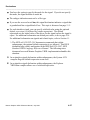
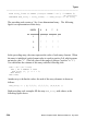
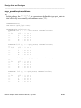
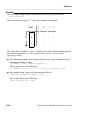
The result of the preceding example is a one-dimensional array mem_d with the
following value:
mem_d
2-8
0
1
2
3
4
5
1
0
0
0
0
1
Mentor Graphics VHDL Reference Manual, July 1994
Expressions
________________________________________________________________________________________________________________________
From the previous example, the following code represents the array aggregate:
mem_d := ( start | offset => 1, OTHERS => 0);
The element association in the preceding example relates a choice of start or
offset (that have a value of "1") to elements "0" and "5" of the array mem_d. All
other elements of the array are assigned a value of "0". Each choice value must
specify index values for the one-dimensional array.
Each element association that you use relates an expression to one or more
elements of an array. A named element association is an element association if
you specify the array elements by using the construct "choices", as the previous
example shows. An easy way to determine if there is a named element
association is to look for the delimiter "=>".
A positional element association is an element association in which each
expression implicitly specifies the element of the array by location. For example,
the first expression specifies the first element, and the second expression
specifies the second element.
For record aggregates, you can use both named and positional association in the
same aggregate. However, all positional elements must appear first, followed by
the named associations.
No association can appear after the reserved word others. If you have an
aggregate with only one element association, you must use a named association.
For a complete discussion on association methods, refer to page 4-31.
The reserved word others indicates that other unspecified elements of the array
take on the value specified after the "=>" delimiter. You can use a string or bit
string literal in multidimensional aggregates where you would use a
one-dimensional array that is of type character.
Mentor Graphics VHDL Reference Manual, July 1994
2-9
Expressions
________________________________________________________________________________________________________________________
Function Calls
A function call is an expression that causes the execution of a function body. The
following example shows a function call.
PROCESS
TYPE state IS (x, z);
VARIABLE s : state;
FUNCTION func1 (st : state) RETURN state IS
BEGIN
RETURN st;
END func1;
BEGIN
-- The function is called
s := func1 (z);
-- assigned the result of
WAIT FOR 10 ns;
-- (in this case z)
END PROCESS;
--The function
-- is declared
and s is
function call
The function name specifies the name of the function you wish to execute. In the
preceding example the function name is func1.
The optional actual parameter part specifies the actual parameters that are
associated with the formal parameters of the function. In the preceding example,
the z in the function call s := func1 (z); is the actual parameter part, and st
is the formal part in the function declaration FUNCTION func1 (st : state).
For the details and rules pertaining to function calls, functions, and parameter
passing, refer to Section 7.
Qualified Expressions
A qualified expression is an expression you use to explicitly describe the type or
subtype (using the type_mark) of an operand that is an aggregate or an
expression. The following diagram shows the syntax for a qualified expression:
qualified_expression ::=
type_mark ’ ( expression )
| type_mark ’ aggregate
Qualified expressions do not perform type conversions. (For more information
on type conversions, refer to page 2-12.) Qualified expressions give you the
ability to eliminate the ambiguity that occurs when you overload operators,
functions, and operands. For example, assume that a package (my_qsim_base) is
2-10
Mentor Graphics VHDL Reference Manual, July 1994
Expressions
________________________________________________________________________________________________________________________
defined that contains the following definitions:
TYPE my_qsim_state
FUNCTION "=" (L, R
FUNCTION "and" (L,
FUNCTION "=" (L, R
IS (’X’, ’0’, ’1’, ’Z’);
: my_qsim_state) RETURN my_qsim_state;
R : my_qsim_state) RETURN my_qsim_state;
: my_qsim_state) RETURN boolean;
Ambiguity occurs when you call this package in a portion of code and also use an
expression such as the following:
(a = b) AND (c = d)
-- a,b,c, and d are type my_qsim_state
In this expression, you do not know which overloaded "=" operator is used. To
resolve this ambiguity, you could use the following qualified expression:
boolean ’ (a = b) AND boolean ’ (c = d)
This qualified expression specifies that the boolean operator "=" is to be used.
Here are some guidelines for the use of qualified expressions:
●
The operand value determines the qualified expression value.
●
The expression or aggregate operand must have the same base type as the type
mark.
●
At the location the qualified expression is evaluated, the expression operand
must belong in the subtype specified by the type mark.
Mentor Graphics VHDL Reference Manual, July 1994
2-11
Expressions
________________________________________________________________________________________________________________________
Type Conversions
S A type conversion provides you with a method for converting from one type to
another closely related type. (For more information on types, refer to Section
5.) Table 2-1 lists the valid type conversions that VHDL can perform.
Table 2-1. Type Conversions
Convert Type
To Type
Integer
Floating point
Floating point
Integer
Integer
Different integer
Floating point
Different floating point
The following diagram shows the syntax for type conversion.
type_conversion ::=
type_mark ( expression )
The following example shows a type conversion:
VARIABLE x : real := 256.55 ;
VARIABLE y, z : integer := 5;
-- variable declarations
--
z := integer (x) + y; -- Converts two different types and
-- assigns the value to "z"
In the preceding example, if the variables x and y are at their default value, the
value of z is 262. When a floating point type is converted to an integer type, the
floating point value converts to the nearest integer. Floating point values that are
halfway between two integers are rounded up.
A type conversion converts the expression to the base type of the type mark. The
type mark designates a type or subtype. If the type mark is a subtype, the range
is checked to determine if the result of the conversion is valid for the subtype.
You can always convert an expression of any type to its same type.
2-12
Mentor Graphics VHDL Reference Manual, July 1994
Expressions
________________________________________________________________________________________________________________________
Type conversions are allowed for all expressions except aggregates, string
literals, allocators, and those involving the literal null. You can use an
expression enclosed by parentheses only when the expression itself is not an
aggregate or string literal.
If the conversion result fails to satisfy the type mark you specify, the conversion
fails, creating an error.
Type conversions also allow you to convert integer types to other integer types
and to convert floating point types to other floating point types. The following
example shows you how to use type conversion on an expression to add values of
two different integer types.
PROCESS
TYPE apples IS RANGE 1 TO 10; --Declare two different
TYPE oranges IS RANGE 1 TO 5; --integer types, "apples" and
--"oranges"
VARIABLE v1, ans: apples; --Declare "v1" and "ans" as apples
VARIABLE v2: oranges;
--Declare "v2" as type oranges.
BEGIN
ans := v1 + v2; -- Illegal! "v1" and "v2" are different types
WAIT FOR 10 ns;
END PROCESS;
To make this expression valid, you can use the following type conversion:
ans := v1 + apples (v2);
-- convert v2 to type apples
Allocators
An allocator is an expression that, when evaluated, creates an anonymous object
and yields an access value that designates that object. The access value can be
thought of as the address of the object. The access value may be assigned to an
access-type variable, which then becomes a designator of (hereafter called a
pointer to) the unnamed object. Such pointers allow access to structures like
FIFOs (first in, first out registers) and linked lists that contain unnamed elements
for which storage is dynamically allocated.
Mentor Graphics VHDL Reference Manual, July 1994
2-13
Expressions
________________________________________________________________________________________________________________________
The BNF description for the allocator construct is as follows:
allocator ::=
new subtype_indication
| new qualified expression
The following list describes the characteristics of an allocator:
●
An allocator creates an object of the type given in the type mark of the
subtype indication or qualified expression.
●
The initial value of the object created by an allocator is determined as follows:
❍
With a subtype indication, the initial value is the same as the default initial
value of any explicitly declared variable of the designated subtype.
❍
With a qualified expression, the initial value is determined by the
expression.
●
Only an index constraint is allowed in the subtype indication of an allocator.
If the created object is an array type, the subtype indication must denote a
constrained subtype or include an explicit index constraint.
●
A subtype indication in an allocator must not include a resolution function.
Declaring an access type is a preliminary step to setting up a pointer. Once an
access type has been declared, you can create a pointer by declaring a variable of
that type and then assigning an access value to that variable using an allocator
expression.
The following example illustrates the process of creating an access type,
assigning an access value to a pointer, and assigning a value to the object pointed
to by the pointer:
1
2
3
TYPE buff_elem_type IS ( 0 TO 255 ) ;
TYPE my_buffer IS ARRAY ( 0 TO 3 ) OF buff_elem_type ;
TYPE buff_ptr IS ACCESS my_buffer ;
4
5
6
7
VARIABLE
VARIABLE
VARIABLE
VARIABLE
2-14
ptr1
ptr2
ptr3
v1 :
: buff_ptr := NEW my_buffer ’ (1, 2, 3, 4) ;
: buff_ptr := NEW my_buffer ;
: buff_ptr := ptr1 ;
buff_elem_type ;
Mentor Graphics VHDL Reference Manual, July 1994
Expressions
________________________________________________________________________________________________________________________
8 ptr2.ALL := ptr1.ALL
9 v1 := ptr1.ALL(0) ;
10 deallocate (ptr1) ;
The preceding example does the following:
●
Line 1 declares a type buff_elem_type for elements of an array object that will
be pointed to by an access type.
●
Line 2 declares the type my_buffer, which is defined as a four-element array
with elements of type buff_elem_type.
●
Line 3 declares an access type, buff_ptr, of type my_buffer. This access type
is now available for variables that will be used as designators of (pointers to)
objects of type my_buffer.
●
Line 4 declares a variable ptr1 of access type buff_ptr and uses an allocator
expression (the reserved word NEW followed by my_buffer), which does three
things:
❍
Allocates enough memory to store an object of type my_buffer.
❍
Creates and assigns a value to an (unnamed) array object of type
my_buffer. In this case, an initial value of (1, 2, 3, 4) is assigned to the
object. You set this up by inserting a tick mark after the type or subtype
name, followed by a value in parentheses, as follows:
type_name ’ ( initial_value )
❍
Assigns an access value (address) to ptr1, which can then be used to
reference the object.
●
Line 5 creates a new pointer, ptr2, and a new object, but in this case the object
assumes a default value. The default value for each element of this object is
the default value for the type buff_elem_type, which is 0
(buff_elem_type’LEFT).
●
Line 6 assigns the access value of ptr1 to ptr3; these pointers now point to the
same object.
●
Line 8 assigns the value of the object pointed to by ptr1 to the object pointed
to by ptr2. The suffix .ALL "dereferences" the pointers, causing the values of
Mentor Graphics VHDL Reference Manual, July 1994
2-15
Expressions
________________________________________________________________________________________________________________________
the objects to which they point to be assigned instead of the "addresses" of the
objects.
●
Line 9 assigns the value of element 0 of the object pointed to by ptr1 to the
variable v1 that was declared in line 8. The .ALL is not actually necessary in
this case, but it does document that the value of the element, rather than its
address, is being assigned.
●
Line 10 deallocates the storage space reserved for the object pointed to by
ptr1. The implicit procedure deallocate exists for each access type you create.
Once storage for an object has been deallocated, it is an error to reference that
object. Pointers that depend on the deallocated pointer (such as ptr3 in the
example) can no longer be used.
For additional information on the use of allocators, refer to
access_type_definition on page 5-31.
VHDL Predefined Operators
S Predefined operators act upon operands and are grouped into six classes based
on their precedence. Table 2-2 lists all the predefined operators by operator
class. The operator classes are listed in the order of precedence, from highest
to lowest.
All the predefined operators in a given operator class have the same precedence.
In an expression, the predefined operator with the highest precedence is applied
to the operands first, following the rules of mathematics. However, you can use
parentheses to control the order of evaluation in an expression (and
non-associative operators, such as NAND, require parentheses to determine the
order of evaluation). You cannot change the precedence of a predefined operator.
For examples, refer to page 2-22.
2-16
Mentor Graphics VHDL Reference Manual, July 1994
Expressions
________________________________________________________________________________________________________________________
Table 2-2. Operators by Precedence
Operator Class
Operators
Miscellaneous operator
** abs not
Multiplying operator
* / mod rem
Sign
+ -
Adding operator
+ - &
Relational operator
= /= < <= > >=
Logical operator
and or nand nor xor
The predefined operator not is a logical operator that has the precedence of a
miscellaneous operator. Therefore, it does not appear with the other logical
operators.
In most cases, both the left and right operands are evaluated before the predefined
operator is applied. The exception is the logical operators defined for the types
bit and Boolean. In this case, the right operand is evaluated only if the left
operand does not possess adequate information to determine the operation result.
These operations are called short-circuit operations. The following subsections
discuss in detail each operator class that Table 2-2 lists.
Important Notes About Operators
●
The operands used with an operator (or any expression) must be readable;
they must be of mode in or inout.
●
Floating point arithmetic in VHDL is not always exact. The accuracy of the
results depends on machine-specific factors, such as size of storage for
floating point numbers, size of registers, and library routines for
exponentiation and logarithms. For this reason, you should never use the "="
operator to compare two floating point numbers or even a floating point
number with a literal.
For example, instead of writing as a condition
IF(x = 0.125) THEN ...
Mentor Graphics VHDL Reference Manual, July 1994
2-17
Expressions
________________________________________________________________________________________________________________________
a better way to check for this condition is
IF( abs(x - 0.125) < tolerance ) THEN ...
where tolerance is some suitable value that you have selected.
The fact that the symbol for the relational operator "<=" (less than or equal)
and the delimiter for signal assignment "<=" are the same can be confusing in
some situations. For an example of when this can produce valid code that
gives completely different results than you might expect, refer to page 6-25.
●
Miscellaneous Operators
Miscellaneous operators have the highest precedence of the predefined operators
and have the following syntax:
miscellaneous_operator ::=
** | abs | not
Table 2-3 lists the miscellaneous operators, their operation, and valid types for
the operands and result. For more information on types, refer to Section 5.
Table 2-3. Miscellaneous Operators
Predefined Operation
Operator
**
Left
Operand
Type
Exponentiation Any integer
type
Any floating
point type
abs
Absolute value None
Right
Operand
Type
Result Type
Predefined
type integer
Same as left
operand
Predefined
type integer
Same as left
operand
Any numeric
type
Same as right
operand
The predefined operator not is a logical operator that has the precedence of a
miscellaneous operator. Therefore, not is discussed with the other logical
operators on page 2-31. An example using the miscellaneous operators ** and
abs follows:
2-18
Mentor Graphics VHDL Reference Manual, July 1994
Expressions
________________________________________________________________________________________________________________________
PROCESS
VARIABLE a, b, c, e, result, answer : integer := 2;
CONSTANT d : integer := -2;
BEGIN
a := b + c;
result := (e ** 8) / (ABS d); -- "result" equals +128
answer := 8 ** (ABS d);
-- "answer" equals +64
answer := (ABS d) ** (ABS d); -- "answer" equals +4
WAIT FOR 10 ns;
END PROCESS;
Exponentiation using an integer exponent (right operand) is equivalent to
multiplying the left operand by itself for the number of times specified by the
absolute value of the right operand. It is an error to use a negative integer
exponent.
When you use a negative exponent, the operation result is the reciprocal of the
value returned using the absolute value of the exponent. You can use only
negative exponents with left operands that are floating point types.
NOTE
Floating point arithmetic in VHDL is not always exact. The
accuracy of a result depends on machine-specific factors such as
size of storage for floating point numbers, size of registers, and
library routines for exponentiation and logarithms. Therefore, an
operation such as (2.0)**(-3) may not always produce a result
of exactly 0.125.
When you use an exponent that has a value of zero, the operation result is a value
of one. When you use predefined operator abs, the right operand value is always
converted to a non-negative value.
Mentor Graphics VHDL Reference Manual, July 1994
2-19
Expressions
________________________________________________________________________________________________________________________
Multiplying Operators
S The following BNF syntax description shows the multiplying operators. The
multiplication operator "*" and the division operator "/" have their
conventional definitions. Table 2-4 lists the multiplying operators, their
operation, and the operand and result type.
multiplying_operator ::=
* | / | mod | rem
The rem (remainder) operator is defined in terms of integer division by the
following identity:
A = (A/B) * B + (A rem B)
The operation (A rem B) result has the sign of A and has an absolute value less
than the absolute value of B.
Integer division satisfies the following identity, which states that if A/B is
negative, the result truncates towards zero:
(-A)/B = -(A/B) = A/(-B)
The mod (modulus) operator satisfies the following relation:
A = B * integer_value + (A mod B)
The operation (A mod B) result has the sign of B and has an absolute value less
than the absolute value of B.
The right operand for the mod, /, and rem operators cannot be a value of zero.
An example of mod and rem follows:
PROCESS (sens_list)
CONSTANT a : integer := -7;
CONSTANT b : integer := 3;
VARIABLE x, y : integer;
BEGIN
x := a MOD b; -- x := +2
y := a REM b; -- y := -1
END PROCESS;
2-20
Mentor Graphics VHDL Reference Manual, July 1994
Expressions
________________________________________________________________________________________________________________________
Table 2-4. Multiplying Operators
Predefined
Operator
*
/
/ (cont.)
mod
rem
Operation
Left
Operand
Type
Multiplication Any integer
type
Any floating
point type
Any physical
type
Any physical
type
Predefined
type integer
Predefined
type real
Division
Any integer
type
Any floating
point type
Any physical
type
Any physical
type
Division
Any physical
(cont.)
type
Modulus
Any integer
type
Remainder
Any integer
type
Mentor Graphics VHDL Reference Manual, July 1994
Right
Operand
Type
Same as left
operand
Same as left
operand
Predefined
type integer
Predefined
type real
Any physical
type
Any physical
type
Same as left
operand
Same as left
operand
Predefined
type integer
Predefined
type real
Same as left
operand
Same as left
operand
Same as left
operand
Result type
Same as left
operand
Same as left
operand
Same as left
operand
Same as left
operand
Same as right
operand
Same as right
operand
Same as left
operand
Same as left
operand
Same as left
operand
Same as left
operand
Universal
integer
Same as left
operand
Same as left
operand
2-21
Expressions
________________________________________________________________________________________________________________________
Sign
The predefined sign operators "+" and "-" have their conventional definition. The
positive "+" represents the identity function, and the negative "-" represents the
negation function. For the predefined sign operators, the operand and result have
the same type. The predefined sign operators are also called unary operators (as
are abs and not). The formal syntax is shown as follows:
sign ::=
+|The precedence of the predefined sign operators places restrictions on where you
can use them. A signed operand cannot follow these operators:
●
A multiplying operator (For information on multiplying operators, refer to
page 2-20.)
●
A miscellaneous operator (For information on miscellaneous operators, refer
to page 2-18.)
●
An adding operator (For additional information, refer to "Adding Operators").
For example:
A
B
Z
A
* - B
/ + C
** - B
+- B
--Illegal
--Illegal
--Illegal
--Illegal
exp.,
exp.,
exp.,
exp.,
sign
sign
sign
sign
follows
follows
follows
follows
multiplying operator.
multiplying operator.
miscellaneous operator.
an adding operator.
If you use parentheses, the previous examples can be written as legal expressions.
For example:
A
B
Z
A
2-22
* (- B)
/ (+ C)
** (- B)
+ (-B)
-----
legal
legal
legal
legal
expression
expression
expression
expression
Mentor Graphics VHDL Reference Manual, July 1994
Expressions
________________________________________________________________________________________________________________________
Adding Operators
The adding operators are as follows:
adding_operator ::=
-|&|+
The predefined adding operators "+" and "-" have their conventional definition.
The concatenation operator (&) defines the connection of one-dimensional arrays
and elements.
Table 2-5 lists the adding operators, their operations, and their operand and result
types.
Table 2-5. Adding Operators
Predefined
Operator
+
&
Operation
Left
Operand
Type
Addition
Any numeric
type
Subtraction
Any numeric
type
Concatenation Any
single-dim.
array type
Any
single-dim.
array type
Same as
element type
of right
operand
Any element
type
Mentor Graphics VHDL Reference Manual, July 1994
Right
Operand
Type
Same as left
operand
Same as left
operand
Same as leftoperand array
type
Same as
element type
of left
operand
Any
single-dim.
array type
Result Type
The same as
left-operand
element type
An array of
element type
Same as left
operand
Same as left
operand
Same as left
operand array
type
Same as leftoperand array
type
Same as
right-operand
array type
2-23
Expressions
________________________________________________________________________________________________________________________
For concatenation, the following three cases apply:
1. Both operands are one-dimensional arrays.
2. Only one operand is a one-dimensional array.
3. Both operands are of the array-element type.
These cases are described in the following paragraphs.
1. Following is an example of concatenation in which the operands are both
one-dimensional arrays:
PROCESS (sens_sig1)
TYPE ref_array IS ARRAY (positive RANGE <>) OF integer;
VARIABLE vector : ref_array (5 TO 9);
--size
VARIABLE null_array: ref_array (5 TO 1); --typing error
VARIABLE one_d : ref_array (6 DOWNTO 3);
--size
VARIABLE new_array : ref_array (9 DOWNTO 1);
--size
BEGIN
new_array := vector & one_d; --Concatenate arrays, size
END PROCESS;
is 5
(TO)
is 4
is 9
is 9
The concatenation operation and the value of new_array from the preceding
sens_sig1 process example is equivalent to the following:
5
6
7
8
9
6
vector
5
6
7
&
8
9
5
4
3
10
one_d
11
12
13
2
1
resultant array from concatenation
9
8
7
6
5
4
3
new_array
The array created by the concatenation of two one-dimensional arrays has the
range and direction of the left operand. In the sens_sig1 process, the left
operand vector has an ascending range (5 TO 9). Therefore, the resultant
array also has an ascending range. The target variable new_array has the range
2-24
Mentor Graphics VHDL Reference Manual, July 1994
Expressions
________________________________________________________________________________________________________________________
and direction specified in its own declaration, not that of the array created from
the concatenation of the other two variables.
The left bound of the resulting array is the left bound of the left operand. If the
left operand is a null array*, the resulting concatenated array uses the range and
direction of the right operand. In the previous sens_sig1 process, the resulting
concatenated array has the left bound of 5 as determined by the left bound of the
left operand vector.
The size of the resulting array matches the total size of the combined right and
left operand array sizes. The elements of the resulting array consist of the
elements of the left operand followed by the elements of the right operand.
2. Following is an example of concatenation in which only one operand is a
one-dimensional array:
PROCESS (sens_sig2)
TYPE ref_array IS ARRAY (positive RANGE <>) OF integer;-VARIABLE vector : ref_array (5 TO 9);
-- size is 5
VARIABLE next_array : ref_array (6 DOWNTO 1);
-- size is 6
BEGIN
next_array := vector & 3; --Concatenate "vector" with "3",
END PROCESS;
The concatenation operation and the value of next_array from the preceding
sens_sig2 process is equivalent to the following:
5
6
7
8
9
vector
5
6
7
&
8
9
resultant array from concatenation
6
5
4
3
2
3
3
10
3
1
3
next_array
___________________
*One way to encounter a null array like null_array is if the range is
reversed, in this case typing TO instead of DOWNTO in the null_array variable
declaration in the sens_sig1 process.
Mentor Graphics VHDL Reference Manual, July 1994
2-25
Expressions
________________________________________________________________________________________________________________________
The resultant array created by the concatenation of a one-dimensional array with
an array element has the range and direction of the index subtype of the left
operand. In the sens_sig2 process, the resulting array uses an ascending
direction as specified in the left operand (vector) declaration:
VARIABLE vector : ref_array (5 TO 9);
The left bound of the resulting array is the left bound of the index subtype of the
left operand. In the sens_sig2 process, the left bound of the index subtype of
the left operand vector is 5. The elements of the resulting array consist of the
elements of the left operand followed by the elements of the right operand.
Had the concatenation in the sens_sig2 process placed the single element as the
left operand as shown below, the same rules would apply.
next_array := 3 & vector; --Concatenate "3" with "vector"
The single element "3" is viewed as an implied one-dimensional array with one
element. The resultant array created by the concatenation of an array element
with a one-dimensional array has the range and direction of the index subtype of
the left operand. In this case, the resultant array from the concatenation starts
with an index of 1 and has a range of 1 to 6. The following paragraphs include a
description of how a single element is treated as an implied array.
3. Following is an example of concatenation in which both operands are of the
same type as an array element type:
PROCESS (sens_sig3)
TYPE ref_array IS ARRAY (positive RANGE <>) OF integer;
VARIABLE x, z : integer;
VARIABLE element_array : ref_array (6 TO 7);
BEGIN
x := 3;
z := 5;
element_array := x & z; --Concatenate to form 2-elem. array
END PROCESS;
The concatenation operation and the value of element_array from the
preceding sens_sig3 process is equivalent to the following:
2-26
Mentor Graphics VHDL Reference Manual, July 1994
Expressions
________________________________________________________________________________________________________________________
1 TO 1
3
1 TO 1
5
&
1 2
5
3 resultant array from concatenation
6
3
7
5
element_array
When you concatenate two non-array objects, each non-array object is treated as
a one-dimensional array containing one element. It is important that at least one
array type declaration is visible in the current scope and that this visible array
type declaration contain an element type that matches the type of the elements
you are concatenating. In the case of the sens_sig3 process, variables x and z
are both of type integer, which is the same as the elements in arrays of type
ref_array.
In the sens_sig3 process, there is only one visible array type declaration that
has an element type that matches the type of the variables being concatenated.
This means that the left bound and range of each of the implied one-element
arrays are determined by the ref_array type declaration. Each element of the
implied array has a left bound of 1 (the left bound of the positive <> value set)
and an ascending range as determined by the range of the positive subtype
declaration (SUBTYPE positive IS integer RANGE 1 TO integer’high;).
The range of the implied arrays for x and z are 1 to 1.
Had the following type declaration also been included in the sens_sig3 process,
overloading rules would determine which array type declaration to use to
determine the left bound and range of the implied arrays for x and z.
TYPE ref_array2 IS ARRAY (natural <>) OF integer; --unconst.
Now that we have determined what the implied arrays for x and z look like, we
can determine the left bound and range of the array that results from the
concatenation of the two implied arrays for x and z. The resultant array from the
concatenation of the two implied arrays has the range and direction of the index
subtype of the implied array of the left operand. In the sens_sig3 process, the
left bound of the index subtype of the implied array is 1 and the range is
Mentor Graphics VHDL Reference Manual, July 1994
2-27
Expressions
________________________________________________________________________________________________________________________
ascending. The elements of the resulting array consist of the left operand
elements followed by the right operand elements.
You can also concatenate items to form a bus. The following example shows the
initialization of a four-bit type called my_qsim_state_vector:
VARIABLE a_bus: my_qsim_state_vector(0 TO 3); --variable decl.
a_bus := ’0’ & ’1’ & ’Z’ & ’X’ ; -- Assign initial values
a_bus := "01ZX";
-- (or do it this way)
In the preceding example, the four bits are concatenated to form a bus. There is a
natural inclination to assign a bus without using the "&" operator, or by using
single quotes, creating an illegal condition, as follows:
a_bus := ’01ZX’ ; -- illegal condition
Shift Operators
S The shift operators perform bit shifting and rotation on operands. This release
of System-1076 fully supports the six shift operators defined in the IEEE Std
1076-1993, IEEE Standard VHDL Hardware Description Language Manual.
The following BNF description shows the shift operators:
relational_operator ::=
sll | srl | sla | sra | rol | ror
Relational Operators
The relational operators check for equality, inequality, and the ordering of
operands. The following BNF description shows the relational operators:
relational_operator ::=
= | /= | < | <= | > | >=
Table 2-6 shows the standard VHDL relational operators, their operations, and
their operand and result types. When you are using the standard VHDL operators
(not using an overloaded version of one of these operators), the operands you use
must be of the same type, and the result type is always boolean.
2-28
Mentor Graphics VHDL Reference Manual, July 1994
Expressions
________________________________________________________________________________________________________________________
Table 2-6. VHDL Relational Operators
Operator
Operation
Operand Type
Result Type
=
Equality
Any type except file types Boolean
/=
Inequality
Any type except file types Boolean
<
Ordering
Any scalar or discrete
array type
Boolean
<=
Ordering
Any scalar or discrete
array type
Boolean
>
Ordering
Any scalar or discrete
array type
Boolean
>=
Ordering
Any scalar or discrete
array type
Boolean
Predefined Equality and Inequality Operators
As Table 2-6 shows, the equality and inequality operators are predefined for all
types, except file types.
The equality operator "=" returns a value of TRUE if the left and right operands
are equal. Otherwise, a value of FALSE is returned. The inequality operator
"/=" returns a value of FALSE if the left and right operands are equal.
Otherwise, a value of TRUE is returned.
When you use two scalar values of the same type as operands, they are equal only
if their values are the same. When you use two composite values of the same
type as operands, they are equal only if the following conditions exist:
●
Each element of the left operand has a matching element in the right operand.
(The left operand is no larger than the right operand.)
●
Each element of the right operand has a matching element in the left operand.
(The right operand is no larger than the left operand.)
●
The matching elements in the left and right operands are equal.
Mentor Graphics VHDL Reference Manual, July 1994
2-29
Expressions
________________________________________________________________________________________________________________________
Using the preceding conditions, two null arrays of the same type are always
considered equal.
When two one-dimensional arrays are compared, matching elements are
determined by matching index values. Index values match if the left bound
element values of the index ranges match. If the left bound element values
match, the next element values to the right are compared. This process continues
until the right bound of one of the arrays is reached.
Predefined Ordering Operators
As Table 2-6 shows, the ordering operators are predefined for any scalar or
discrete array type. A discrete array type is a one-dimensional array that contains
elements that are of enumeration or integer types. Each ordering operator returns
a value of TRUE if the specified relation is satisfied. Otherwise, a value of
FALSE is returned.
Scalar type ordering operations are defined by the left and right operand relative
values. For discrete array types, the relational operator "less than" (<) means that
the left operand is less than the right operand if the following conditions are
satisfied:
●
The left operand is a null array and the right operand is not a null array.
●
The left and right operands are not null arrays. If they are not null arrays, one
of the following conditions must be met:
❍
The left-most element of the left operand is less than the left-most element
of the right operand.
❍
The left-most element of the left operand is equal to the left-most element
of the right operand, and the tail of the left operand is less than the tail of
the right operand.
The tail of an operand is the remaining elements to the right of the
left-most element. The tail can be null.
The relational operator "less than or equal to" (<=), for discrete array types is true
if either "<" or "=" is true for the left and right operands you specify.
2-30
Mentor Graphics VHDL Reference Manual, July 1994
Expressions
________________________________________________________________________________________________________________________
Using the definition of equality and less than, the remaining relational operators
can be defined as follows:
●
"Less than" is the complement to "greater than or equal to".
●
"Greater than" is the complement to "less than or equal to".
Logical Operators
The logical operators are predefined for the types bit and boolean and
one-dimensional arrays of type bit or boolean. The logical operators have their
conventional definitions (0 is false and 1 is true). The following syntax
description shows the logical operators:
logical_operator ::=
and | or | nand | nor | xor | xnor
If the operands are arrays and the logical operator is a logical operator other than
not, then the following information applies to the expression:
●
The operands must be the same length.
●
The operation is accomplished by computing the result of applying the
operator to matching elements of the the arrays.
●
The result is an array of the same subtype as the left operand with the same
index range.
If the operand is an array and the logical operator is not, the not operation is
performed on each array element and the result is an array of the same subtype as
the operand with the same index range.
There are other expressions that are special cases that do not fall into the
expression categories in the previous discussion about expressions. These
expressions are identified as follows and are further described in the following
subsections:
●
Static expressions
●
Universal expressions
Mentor Graphics VHDL Reference Manual, July 1994
2-31
Expressions
________________________________________________________________________________________________________________________
Static Expressions
Static expressions fall into two categories:
●
Locally static
●
Globally static
A locally static expression is an expression that can be completely evaluated
when the design unit in which it appears is evaluated. The values for locally
static expressions depend only on those declarations that are local to the design
unit or on any packages used by the design unit.
A locally static expression must use operators that are predefined and all the
operands and results of the expression must be scalar types. Therefore, if you use
an overloaded operator in an expression, it is not a locally static expression.
Every operand in the expression must be a locally static operand. A locally static
operand is one of the items listed in Table 2-7.
A globally static expression is an expression that can be evaluated when the
design hierarchy where the expression appears is elaborated. The values for
globally static expressions may depend upon declarations that appear in other
design units. The values for globally static expressions are determined when the
design unit is elaborated.
A globally static expression must use operators that are predefined. Therefore, if
you use an overloaded operator in an expression, it is not a globally static
expression. Every operand in the expression must be a globally static operand.
A globally static operand is one of the items listed in Table 2-8.
2-32
Mentor Graphics VHDL Reference Manual, July 1994
Expressions
________________________________________________________________________________________________________________________
Table 2-7. Local Static Operands
Locally Static
Operand
Constant
Predefined
attribute
Function call
Literal
Qualified
expression
Locally static
expression
Rules For the Locally Static Operand
No deferred constants are allowed. Constant must be
declared with a locally static subtype and initialized
using a locally static expression.
Must be an attribute of a locally static subtype that is a
value or a function with actual parameters that are
locally static.
The function name must designate a predefined
operator. Actual parameters must be locally static.
Any scalar literal type.
The type mark must designate a locally static subtype.
The operand must be a locally static expression.
May be enclosed by parentheses.
Mentor Graphics VHDL Reference Manual, July 1994
2-33
Expressions
________________________________________________________________________________________________________________________
In this manual, several items are defined as locally static :
●
Locally static range: a range with bounds that are locally static expressions.
●
Locally static range constraint: a range constraint with a range that is locally
static.
●
Locally static scalar subtype: a scalar type (or subtype) or base type that is
formed by restricting a locally static subtype by imposing a locally static
range.
●
Locally static discrete range: a locally static subtype or locally static range.
●
Locally static index constraint: an index constraint in which each index
subtype of the corresponding array type is locally static. Each discrete range
is locally static.
●
Locally static array subtype: a constrained array subtype that is formed by
restricting an unconstrained array type using a locally static index constraint.
Ranges are discussed on page 5-5, scalar types are discussed on page 5-4, and
arrays are discussed on page 5-22.
2-34
Mentor Graphics VHDL Reference Manual, July 1994
Expressions
________________________________________________________________________________________________________________________
Table 2-8. Global Static Operands
Globally Static
Operand
Locally static
operand
Constant
Predefined
attribute
Function call
Qualified
expression
Globally static
expression
Aggregate
Rules For the Globally Static Operand
Any locally static operand is considered a globally
static operand.
Deferred and generic constants are allowed. Constants
must be declared with globally static subtype.
Must be an attribute of a globally static subtype that is
a value, range, or a function with actual parameters that
are globally static.
The function name must designate a predefined
operator. Actual parameters must be globally static.
The type mark must designate a globally static subtype.
The operand must be a globally static expression.
May be enclosed by parentheses.
Must have a globally static subtype, and its element
associations can contain only globally static
expressions.
In this manual, several items are defined as being globally static:
●
Globally static range: a range with bounds that are globally static
expressions.
●
Globally static range constraint: a range constraint with a range that is
globally static.
●
Globally static scalar subtype: a scalar type (or subtype) or base type that is
formed by restricting a globally static subtype by imposing a globally static
range.
●
Globally static discrete range: a globally static subtype or globally static
range.
●
Globally static index constraint: an index constraint in which each index
subtype of the corresponding array type is globally static. Each discrete range
is globally static.
Mentor Graphics VHDL Reference Manual, July 1994
2-35
Expressions
________________________________________________________________________________________________________________________
●
Globally static array subtype: a constrained array subtype that is formed by
restricting an unconstrained array type using a globally static index constraint.
Ranges are discussed on page 5-5, scalar types are discussed on page 5-4, and
arrays are discussed on page 5-22.
Universal Expressions
A universal expression is an expression that has a result type of universal_integer
or universal_real. For a discussion about universal_integer and universal_real,
refer to pages 5-9 and 5-12, respectively.
For any integer-type predefined operation, there is an equivalent
universal_integer predefined operation. Likewise, for any floating-point type
predefined operation, there is an equivalent universal_real predefined operation.
Table 2-9 lists the additional operand and result types for the multiplication and
division predefined operators.
Table 2-9. Universal Expression Operators
Operator
Operation
Left
Operand
Type
Right
Operand
Type
Result Type
*
Multiplication
universal
real
universal
integer
universal
real
universal
integer
universal
real
universal
real
universal
real
universal
integer
universal
real
/
2-36
Division
Mentor Graphics VHDL Reference Manual, July 1994
Naming, Scope, and Visibility
________________________________________________________________________________________________________________________
Section 3
Naming, Scope, and Visibility
S This section discusses two topics: the concept of names and the concept of
scope and visibility. You must identify every design item you declare with some
form of name. The system requires a design item to be named before the system
can manipulate the design item. Each design you create may have hundreds of
names within it. This collection of names forms a name space. There can only
be one declaration of a given name per name space, and the collection of name
spaces forms the complete name space.
To make the task of managing the complete name space controllable, VHDL
provides scope and visibility rules. The scope of a design item is the region of
text in which the declaration of the item has effect. Visibility rules define where
the name from a declaration can be seen. The following ordered list shows the
topics described in this section:
Naming
Simple Names
Selected Names
Indexed Names
Slice Names
Attribute Names
3-3
3-4
3-4
3-8
3-9
3-10
Scope and Visibility
Declarative Region
Scope
Visibility
Overload Resolution
3-12
3-12
3-13
3-16
3-24
Mentor Graphics VHDL Reference Manual, July 1994
3-1
Naming, Scope, and Visibility
________________________________________________________________________________________________________________________
Design Units
Design Entities
Configurations
Packages
Attributes
Components
Types
Signals
Statements
Subprograms
Declarations
Expressions
Lexical Elements
Naming, Scope,
and Visibility
Naming
Scope & Visibility
Simple Names
Selected Names
Indexed Names
Slice Names
Attribute Names
Operator Symbols
Figure 3-1. Naming, Scope, and Visibility
3-2
Mentor Graphics VHDL Reference Manual, July 1994
Naming, Scope, and Visibility
________________________________________________________________________________________________________________________
Naming
Your VHDL code must be able to refer to a declared item to act upon it.
Therefore, each declared item must have a name. Names formally designate one
of the following:
●
Explicitly or implicitly declared items
●
Subelements of composite objects
●
Attributes
●
Objects denoted by access values
Here are some examples that show the use of names:
VARIABLE vcc : integer := 5; -- "vcc" is a simple name
test’base’left -- "test’base’left" is an attribute name
To refer to a design item, you use the name assigned to that design item.
Declared items such as design entities, packages, and procedures are named using
the simple_name construct. In some cases, you may want to reference a certain
portion of an item, such as element of an array or record. In those cases, you
might use an indexed name or selected name. In all, there are six forms of names
you can use, as the following BNF description illustrates.
name ::=
simple_name
| operator_symbol
| selected_name
| indexed_name
| slice_name
| attribute_name
The following subsections show you how to use simple names, selected names,
indexed names, slice names and attribute names. The operator symbol is a name
for an operator that you can overload and use to manipulate objects. This topic is
discussed in the subprogram declaration description on page 7-6.
Mentor Graphics VHDL Reference Manual, July 1994
3-3
Naming, Scope, and Visibility
________________________________________________________________________________________________________________________
Simple Names
When you declare an item using an identifier, you use a simple name. When the
simple name is evaluated, the item to which it refers is determined. Every item
you explicitly declare has a simple name, and some items declared implicitly
have a simple name (such as labels and loop indexes). The following BNF
syntax description shows the related syntax for a simple name:
simple_name ::=
identifier
identifier ::=
letter {[_] letter | digit}
All declarations require simple names. The following are some valid simple
name examples within a line of code:
ARCHITECTURE behave OF shifter IS
--"behave" is the simple name (identifier) in the first line
-- of the architecture_body construct.
ENTITY counter IS
--"counter" is the simple name (identifier) in the first line
-- of the entity_declaration construct.
FUNCTION chk_parity
--"chk_parity" is the simple name (identifier) in the first
-- line of the subprogram_specification construct.
Selected Names
Selected names designate elements of record types, objects pointed to by access
values, and items declared within another item, design library, or package. You
use selected names in use clauses, which are discussed on page 3-22. You can
use a selected name to designate all the items declared in a library or package by
using the reserved word all. You can also use selected names to resolve
overloading conflicts.
The use of selected names to access individual elements of records is discussed
under "record_type_definition," beginning on page 5-29. The use of selected
names for objects pointed to by access values is discussed under "Allocators,"
beginning on page 2-13.
3-4
Mentor Graphics VHDL Reference Manual, July 1994
Naming, Scope, and Visibility
________________________________________________________________________________________________________________________
The following BNF descriptions show the syntax for a selected name:
selected_name ::=
prefix . suffix
suffix ::=
simple_name
| character_literal
| operator_symbol
| all
The following examples show the use of selected names:
USE standard.time;
USE standard.ALL;
---
The item "time" in package standard
All the items in package standard
USE prim_lib.gates.and2; --AND from "gates" in "prim_lib"
USE gen_lib.or2, gen_lib.exor; --OR and XOR gates from gen_lib
The selected, indexed, slice, and attribute names require a prefix. As the
following BNF description shows, the prefix can be either a name or a function
call.
prefix ::=
name
| function_call
When a name prefix is a function call, the suffix designates an attribute, element,
or slice of the function call result. For information on function calls, refer to
page 7-15.
When a name is evaluated, the item designated by the name is determined. If the
name has a prefix, the name or function call designated by the prefix is evaluated.
Throughout this manual, there are several rules that involve a concept called the
longest static prefix. The longest static prefix is equivalent to the static signal
name you use. If you do not use a static signal name, the longest static prefix is
Mentor Graphics VHDL Reference Manual, July 1994
3-5
Naming, Scope, and Visibility
________________________________________________________________________________________________________________________
the static part of the name you use. For example:
sname(5)(7)
sname(5)(7)
Longest Static Prefix
Static Name
In the preceding example, the signal name contains the static expressions
(5)(7), which designate the name as a static signal name. Therefore, the entire
signal name is the longest static prefix. Another example follows:
Non-Static Expression
sname(5)(j)
Static Name
sname(5)
Longest Static Prefix
In the preceding example, j is a variable. Therefore, the expression (j) is
non-static. The longest static prefix is the static part sname(5). Another
example follows:
Non-Static Expression
sname(x)(j)
Static Name
sname
Longest Static Prefix
In the preceding example, j and x are variables. Therefore, the expression
(x)(j) is non-static. The longest static prefix is the static part sname.
3-6
Mentor Graphics VHDL Reference Manual, July 1994
Naming, Scope, and Visibility
________________________________________________________________________________________________________________________
Another form of the selected name is the expanded name. The expanded name
designates one of the following:
●
Primary unit in a design library. In this case, the prefix designates the library,
and the suffix is a primary unit simple name, which you declare within the
library designated by the prefix. For example:
USE design_lib.and_gate ;
●
Item declared in a package. In this case, the prefix designates the package,
and the suffix is not the reserved word all. The simple name character literal
or operator symbol declaration you use as the suffix must be declared
immediately within the package designated in the prefix.
●
All items declared in a package. In this case, the prefix designates the
package, and the suffix is all.
●
Item declared immediately within a named construct. In this case, the prefix
designates one of the following:
❍
Entity
❍
Architecture
❍
Subprogram
❍
Block statement
❍
Process statement
❍
Loop statement
The suffix must not be the reserved word all. The simple name character
literal or operator symbol declaration you use as the suffix must be declared
immediately within the construct designated in the prefix.
An expanded name used to designate an item declared immediately within a
named construct is allowed only within the construct named in the prefix.
The suffix is the item in a design library or package that you wish to select. This
selection can be a single item, several items, or all the items that the design
library or package contains. To select all the items, you use the reserved word
all.
Mentor Graphics VHDL Reference Manual, July 1994
3-7
Naming, Scope, and Visibility
________________________________________________________________________________________________________________________
Indexed Names
You use an indexed name to designate an element of an array. The following
BNF description shows the syntax for an indexed name.
indexed_name ::=
prefix ( expression { , expression } )
The prefix you use must be valid for array types. For information on array types,
refer to page 5-22.
You use one or more expressions to designate the index value for an array
element. For example:
PROCESS
TYPE one_array IS ARRAY (positive RANGE <>) OF integer;
TYPE two_array IS ARRAY (positive RANGE <>,
positive RANGE <>) OF integer;
VARIABLE my_matrix : one_array (1 TO 5);
VARIABLE d_matrix : two_array (1 TO 10, 1 TO 10);
VARIABLE y, w : integer;
BEGIN
y := my_matrix(3); --The element in the position of the
--array my_matrix designated by the index value 3
W := d_matrix(2,3); --The element in the position of the
--two-dimensional array 2d_matrix
--designated by the index 2,3
WAIT FOR 10 ns;
END PROCESS;
You must use a corresponding number of expressions for the dimension of the
array. In the preceding example, if you designate an element of d_matrix, you
need two expressions (for example (2,3)). If you use one expression (for
example (3)), an error occurs, because another dimension is needed to locate the
array element.
3-8
Mentor Graphics VHDL Reference Manual, July 1994
Naming, Scope, and Visibility
________________________________________________________________________________________________________________________
Slice Names
A slice name designates a one-dimensional array that is created from a
consecutive portion of another one-dimensional array. A slice of a design item
equates to a new design item of the same type. The following diagram shows the
syntax for a slice name:
slice_name ::=
prefix ( discrete_range )
The following example shows the concept of using a slice name:
PROCESS (sens_signal)
TYPE ref_array IS ARRAY (positive RANGE <>) OF integer;
VARIABLE array_a : ref_array (1 TO 12); -- declare "array_a"
VARIABLE array_b : ref_array (1 TO 4); -- declare "array_b"
BEGIN
FOR i IN 1 TO 12 LOOP
--Load array with values
array_a (i) := i + 10 ; --11 through 22
END LOOP;
array_b := array_a (6 TO 9); -- slice of "array_a"
END PROCESS;
Figure 3-2 illustrates the preceding example.
1
array_a 11
2
12
3
13
4
14
5
15
array_b
6
7
8
9
16
17
18
19
1
2
3
4
16
17
18
19
10
11
12
20
21
22
Figure 3-2. Slice Name Concept
Mentor Graphics VHDL Reference Manual, July 1994
3-9
Naming, Scope, and Visibility
________________________________________________________________________________________________________________________
The prefix you use must be valid for one-dimensional array types. For
information on array types, refer to page 5-22.
You specify the array bounds of the slice by using a discrete range. The discrete
range you specify must be of the same type as the index of the array you are
slicing. If you specify a null discrete range or a range direction opposite to the
object designated by the slice name prefix, the slice is a null slice.
When a slice name is evaluated, an error occurs if you specify a discrete range
with bounds that do not belong to the index range specified in the prefix array.
No error occurs if a null slice is specified, because the null slice bounds do not
have to be a subtype of the index range specified by the prefix array.
Some slice name examples follow:
-- Begin by declaring a constant, signal, and variable:
-TYPE this_array IS ARRAY (natural RANGE <>) OF integer;
CONSTANT result: this_array (0 TO 100) := (OTHERS => 0);
SIGNAL traffic_lights: bit_vector (0 TO 7);--Declare a signal
VARIABLE test: this_array (10 DOWNTO 1); --Declare a variable
-- Slices of the constant, signal, and variable:
-result (25 TO 50)
--Slice of the array result
traffic_lights (5 TO 4) --Null slice because wrong direction
test (5 DOWNTO 1)
--Slice of the array test
result (0 DOWNTO 100) --Null slice, because range of slice
--is opposite of the range declared for the array result.
--(Also, a range of 0 downto 100 is null by itself.)
Attribute Names
An attribute name consists of a prefix and an attribute designator. For predefined
attributes, the prefix denotes an array, block, signal, or type. The prefix for a
user-defined attribute may denote an entity declaration, an architecture body, a
configuration, a procedure, a function, a package, a type, a subtype, a constant, a
signal, a variable, a component, or a label.
The attribute designator is the simple name for the predefined attribute. The
attribute returns certain information about the item named in the prefix, such as
length of an array or whether a signal is active. The complete discussion of
attributes is covered in Section 10. The following diagram shows the related
3-10
Mentor Graphics VHDL Reference Manual, July 1994
Naming, Scope, and Visibility
________________________________________________________________________________________________________________________
syntax for an attribute name.
attribute_name ::=
prefix ’ attribute_designator [ ( expression ) ]
attribute_designator ::=
attribute_simple_name
The expression in the attribute name may be required or may be optional,
depending on the particular attribute definition.
The following examples show the declaration of two types and the use of
attribute names to determine information on these types. These are source-code
fragments taken out of context.
TYPE color IS(red, white, blue, orange, purple); --type decl.
TYPE vector IS ARRAY (1 TO 10, 1 TO 15) OF integer;
color’val(2) --Returns the value of element in position 2 of
--the type "color" which is blue (positions
--start at zero)
vector’right(1) --returns right bound of the specified index
-- "1" in the array "vector" which is 10
There are several terms used to describe to a certain subclass of names, as the
following list shows:
●
Static name
●
Static expression
●
Static signal name
Indexed names have an expression as part of the language construct. If you use a
static expression, the name is a static name.
A static expression* is one whose value is determined either at compile time or at
elaboration time. For example, when you use a signal that is declared in a
previous design unit, the signal value is not known in the current design unit.
Therefore, using this signal name in an expression makes it a non-static
___________________
*For more information on static expressions, refer to page 2-32.
Mentor Graphics VHDL Reference Manual, July 1994
3-11
Naming, Scope, and Visibility
________________________________________________________________________________________________________________________
expression. For detailed information about the design unit, refer to Section 9.
If you use a static name to designate a signal, the name is considered a static
signal name.
Scope and Visibility
S Scope and visibility are concepts that are closely related. The scope is the
region of code text over which an item exists (declarative region). Within the
scope, visibility refers to an item that has a unique name that you can reference.
If an item is hidden, it is not visible without using a selected name. This topic is
discussed on page 3-17.
Using the concepts of scope and visibility and by using the rules of overloading,
you can control the name space. That is, you can control where names have
effect without worrying about the global effects of manipulating a named item.
This becomes a very important factor when your design contains hundreds of
names. The following subsections describe in detail the following items:
●
The declarative region
●
The concept of scope and the scope rules
●
The concept of visibility and the visibility rules
●
Overloading concepts
Declarative Region
Scope and visibility are defined in terms of declarative regions. The declarative
region is a part of the text of a description. The declarative region is formed by
the text of the following items:
●
Component declaration (page 8-21)
●
Entity declaration (combined with an architecture body) (page 8-4)
●
Package declaration (combined with a package body if it exists) (page 9-13)
●
Subprogram declaration (combined with a subprogram body) (page 7-6)
3-12
Mentor Graphics VHDL Reference Manual, July 1994
Naming, Scope, and Visibility
________________________________________________________________________________________________________________________
●
Block statement (page 6-12)
●
Loop statement (page 6-36)
●
Process statement (page 6-41)
Each declarative region in the preceding list is associated with a corresponding
declaration or statement. The declaration is immediately within a declarative
region if the corresponding region is the innermost region enclosing the
declaration. This innermost region does not include the declarative region (if it
exists) of the declaration. The following example shows a skeleton of a block
statement and the declarative region:
test_block:
BLOCK
-- declarative region
TYPE test IS 1 TO 10;
BEGIN
-- concurrent statements
END BLOCK test_block;
Scope
Scope is the region of code over which a declared item has effect. For example,
if you declare objects inside a block statement, the scope of the objects extends
from the point where you first name the objects to the end of the block statement.
Figure 3-3 shows an architecture body that contains a procedure within a process.
Region A shows the scope of the subprogram specification (procedure); region B
shows the scope of the process statement; and region C shows the scope of the
architecture body.
Mentor Graphics VHDL Reference Manual, July 1994
3-13
Naming, Scope, and Visibility
________________________________________________________________________________________________________________________
ARCHITECTURE
SIGNAL
BEGIN
PROCESS
VARIABLE
PROCEDURE
BEGIN
.
A
.
B
C
.
END;
BEGIN
.
END PROCESS;
.
END;
Figure 3-3. Scope
Figure 3-4 shows that even though the architecture body can be stored and
evaluated in a file separate from the entity declaration, an item declared in the
entity declaration (such as signal1) is visible throughout region C. An item
declared in a package header is visible to the package header and the package
body.
3-14
Mentor Graphics VHDL Reference Manual, July 1994
Naming, Scope, and Visibility
________________________________________________________________________________________________________________________
ENTITY en1 IS
SIGNAL1
In File "entity1.hdl"
END en1;
ARCHITECTURE a1 OF en1 IS
SIGNAL2
In File "arch1.hdl"
BEGIN
PROCESS
VARIABLE
PROCEDURE
BEGIN
C
.
.
A
B
.
END;
BEGIN
.
END PROCESS;
.
END a1;
Figure 3-4. Scope of Entity Plus Architecture
Scope Rules
The scope rules discussed in this subsection are valid for all declaration forms,
implicit or explicit.
Immediate scope is the scope of a declaration that is directly within a declarative
region. Table 3-1 lists the cases in which a declaration extends beyond its
immediate scope.
Mentor Graphics VHDL Reference Manual, July 1994
3-15
Naming, Scope, and Visibility
________________________________________________________________________________________________________________________
Table 3-1. Immediate Scope Exceptions
Declaration
Occurring Within
Formal parameter
Subprogram declaration *
Declaration
Package declaration **
Local generic
Component declaration
Local port
Component declaration
Formal generic
Entity declaration
Formal port
Entity declaration
* This extension is also valid if a separate subprogram declaration is
missing and the subprogram body is used as the declaration.
** The declaration must occur immediately within the package
declaration.
The library unit scope and logical library name scope in a design library extend
beyond the immediate scope.
Visibility
Visibility refers to an item that has a unique name, thereby making it an item you
can refer to in a code description. An item may be hidden from other portions of
code by the nesting of language constructs and by the use of homographs. Figure
3-5 shows the variable declared within the procedure is visible only to the
highlighted area (or its scope).
An item declared in the entity declaration such as signal1 in Figure 3-4 can be
visible to the entire scope identified by region C unless it is hidden, as described
later.
3-16
Mentor Graphics VHDL Reference Manual, July 1994
Naming, Scope, and Visibility
________________________________________________________________________________________________________________________
ARCHITECTURE
SIGNAL
BEGIN
PROCESS
VARIABLE
PROCEDURE
VARIABLE
BEGIN
END;
.
.
.
BEGIN
.
END PROCESS;
.
END;
Figure 3-5. Visibility
Visibility Rules
The visibility rules establish the meaning of an identifier. The possible meanings
of the occurrence of this identifier are determined during evaluation. The
following list shows the two possible results of this determination:
●
One possible meaning: the visibility rules alone find the declaration that
defines the identifier meaning. If this declaration does not exist, the visibility
rules alone determine that the identifier is not legal.
●
Multiple meanings: the visibility rules find multiple meanings for the
identifier. In other words, it is overloaded. Within the related context, one
visible declaration is used if the overloading rules have been met. For
information on overloading rules, refer to page 3-24.
An identifier can be made visible by two different means, as the following list
shows:
Mentor Graphics VHDL Reference Manual, July 1994
3-17
Naming, Scope, and Visibility
________________________________________________________________________________________________________________________
●
Selection: if the item is hidden, it becomes visible only when you use a
selected name. Selected names designate an item declared within another
item. For more information on selected names, refer to page 3-4.
●
Directly visible: if the item is not hidden, it is directly visible. A directly
visible declaration is also visible by selection.
Table 3-2 shows the places where a declaration is visible by selection.
Any declaration that occurs immediately within a declarative region of a
language construct is visible by selection at the suffix of an expanded name. The
prefix of this expanded name must designate the language construct. For more
information on expanded names, refer to page 3-6.
A declaration is directly visible in a specific area of the immediate scope. This
area encompasses the area between the declaration and the end of the immediate
scope, except for areas where the declaration is hidden. You can make a
declaration that occurs immediately within the visible part of a package directly
visible outside the package by using the use clause. For more information on the
use clause, refer to page 3-22.
Two declarations are homographs of each other if they both use a common
identifier and if overloading is allowed for at most one of the two declarations.
There are two homograph cases: one declaration can be overloaded and the other
cannot; or both declarations can be overloaded and they have the same parameter
and result type profile. Only enumeration literals or subprogram declarations can
be overloaded.
Homographs declared within the same declarative region create an error. With
homographs declared in different regions, the inner declaration hides the
corresponding outer declaration within the inner scope region. In this case, the
homograph declared in the outer region is not visible within the inner region.
Two formal parameter lists have the parameter type profile if they have the same
number of parameters in the list and if the parameters at each position in the list
have the same base type. Two subprograms have the same parameter and result
type profile if they both have the same parameter profile and if they are
functions, the functions return a result with the same base type. In the case of
enumeration literals, no homograph exists if the base types are different. For
information on overloading, refer to page 3-24.
3-18
Mentor Graphics VHDL Reference Manual, July 1994
Naming, Scope, and Visibility
________________________________________________________________________________________________________________________
Table 3-2. Visibility by Selection
Design Item
Selected By
Primary unit in library
Suffix in selected name (prefix designates the
library)
Declaration in package
declaration
Suffix in selected name (prefix designates the
package)
Predefined attribute that
applies to a given range
of definition
Attribute designator (after ’) in attribute name.
Formal parameter decl.
of specified subprogram
declaration
Formal designator (before =>) in parameter
association list.
Local generic decl. of
specified component
declaration
Formal designator (before =>) in a named
generic association list of a corresponding
component instantiation statement; or actual
designator (after =>) in generic association list
of a corresponding binding indication
Local port decl. of
specified component
declaration
Formal designator (before =>) in a named port
association list of a corresponding component
instantiation statement; or actual designator
(after =>) in port association list of a
corresponding binding indication
Formal generic decl. of
specified entity decl.
Formal designator (before =>) in generic assoc.
list of a corresponding binding indication
Formal port decl. of
specified entity decl.
Formal designator (before =>) in port assoc. list
of a corresponding binding indication
Element of a record
Suffix in selected name (prefix denotes record)
Figure 3-6 shows an example of hidden declarations and homographs.
Mentor Graphics VHDL Reference Manual, July 1994
3-19
Naming, Scope, and Visibility
________________________________________________________________________________________________________________________
ARCHITECTURE
SIGNAL
BEGIN
PROCESS
VARIABLE x : boolean
PROCEDURE
VARIABLE x : boolean
BEGIN
END;
BEGIN
END PROCESS;
END;
.
A
B
C
.
.
.
.
Figure 3-6. Declaration Hiding and Homographs
In Figure 3-6 variable x is declared within the procedure in scope A and within
the process in scope B. The variable x declared in the process is hidden within
scope A by the variable x declared in the procedure. The variable in scope A is a
homograph of the variable in scope B, because the variables have the same
identifier.
Figure 3-7 shows an example of hidden declarations and overloading that results
in no homograph.
3-20
Mentor Graphics VHDL Reference Manual, July 1994
Naming, Scope, and Visibility
________________________________________________________________________________________________________________________
ARCHITECTURE
FUNCTION x: RETURN integer;
BEGIN
PROCESS
PROCEDURE x;
VARIABLE x : boolean
BEGIN
END;
BEGIN
END PROCESS;
END;
.
A
B
C
.
.
.
.
Figure 3-7. No Homograph Instance
In Figure 3-7, function x is declared in scope C, and procedure x is declared in
scope A. In this case, function x and procedure x are not homographs of each
other because the system can determine a difference between the two x values by
the context. Therefore, overloading is allowed for both of the values. If you
replace the function with a procedure, the two procedures are homographs of
each other (if the procedures have the same parameter type), because the system
cannot determine a difference between the two identifiers.
Mentor Graphics VHDL Reference Manual, July 1994
3-21
Naming, Scope, and Visibility
________________________________________________________________________________________________________________________
use_clause
The use clause allows you to make directly visible a declaration in a package or
library that is visible by selection.
Construct Placement
block_declarative_item, context_item, entity_declarative_item,
package_body_declarative_item, package_declarative_item,
process_declarative_item, subprogram_declarative_item
Syntax
use_clause ::=
use selected_name { , selected_name } ;
Description
You can specify one or more selected names to identify declarations that you
want to become directly visible. (For more information on selected names, refer
to page 3-4.) You can also specify the use of all of the declarations by using the
reserved word all. For example:
USE package_1.test_func1,package_1.test_func2
USE package_2.ALL
-- line 1
-- line 2
Line 1 makes the functions test_func1 and test_func2, from package_1
directly visible. Line 2 makes all the top level declarations of package_2 visible.
For examples of use clauses in relation to libraries, refer to page 9-5.
There are two cases in which a declaration is not made directly visible by the use
clause:
●
The use clause designates a place within the immediate scope of a homograph
of a declaration.
●
Two declarations you wish to make visible have the same designator and are
not a subprogram declaration or an enumeration literal specification.
Any declaration you make directly visible by a use clause does not hide a
previous directly visible declaration in any situation. This is assured by the rules
of the use clause.
There is a situation you must be aware of when utilizing the use clause. If you
have a use clause in one model (Model A for reference) that references a package
3-22
Mentor Graphics VHDL Reference Manual, July 1994
Naming, Scope, and Visibility
________________________________________________________________________________________________________________________
that also contains a use clause, the items that are made visible to the package are
not made directly visible to the original model (Model A). For more information,
see the following example and Figure 3-8.
Example
Figure 3-8 shows an example of multiple use clauses in packages. The figure
shows Model A that contains a use clause that makes all the declarations in
pkg_b directly visible. Within pkg_b is a use clause that makes the function x in
pkg_a visible. Function x is not directly visible to the Model A code, but
function z in pkg_b is directly visible.
Package: pkg_a
Package: pkg_b
FUNCTION
z: RETURN
bit;
FUNCTION x: RETURN bit;
USE pkg_a.x
Model A
USE
pkg_b.all
Figure 3-8. Multiple Use Clauses
Mentor Graphics VHDL Reference Manual, July 1994
3-23
Naming, Scope, and Visibility
________________________________________________________________________________________________________________________
Overload Resolution
When the rules for visibility determine there is more than one acceptable
meaning for an enumeration literal or subprogram name, overload resolution
determines the actual meaning. Overload resolution also determines the actual
meaning of an operator occurrence. All visible declarations are examined to
determine overloading legality. The overloading is legal only if there is one
interpretation of the innermost declaration, specification, or statement (complete
context).
The actual interpretation of the overloaded, complete context, is governed by the
following rules:
●
Scope rules
●
Syntax rules
●
Visibility rules
●
Miscellaneous rules, which include the following:
3-24
❍
Rules requiring expressions or names to have a specified type or the same
type as another expression or name
❍
Rules requiring the type of expressions or names to be of a specified type
class
❍
Rules requiring a specified type to be one of the following:
■
Boolean
■
Character
■
Discrete
■
Integer
■
Physical
■
Real
■
Universal
Mentor Graphics VHDL Reference Manual, July 1994
Naming, Scope, and Visibility
________________________________________________________________________________________________________________________
❍
Rules requiring an appropriate prefix for a specified type
❍
Rules requiring the type of an aggregate to be determined from context
only
❍
Rules requiring the type of the attribute prefix, of the expression in a case
statement, or of the operand of a type conversion being determined
independent of context
❍
Rules for resolution of subprogram calls that are overloaded or for implicit
universal expression conversion
❍
Rules for interpreting discrete ranges that have universal type bounds
❍
Rules for interpreting an expanded name that has a prefix designating a
subprogram
The preceding rules are discussed in the appropriate sections of this manual. To
find the exact page location for the subject you wish to explore in detail, refer to
the index or table of contents. The rules for each of these subjects are discussed
in the context of the complete discussion about the item.
For information about overloading enumeration literals, refer to page 5-19; about
overloading subprograms, refer to page 7-17.
Mentor Graphics VHDL Reference Manual, July 1994
3-25
Declarations
________________________________________________________________________________________________________________________
Section 4
Declarations
This section discusses the subject of declarations and how to use them. A
declaration defines a design item and relates an identifier to that design item. For
the system to manipulate design items, you must declare them explicitly or they
must be declared implicitly. The following ordered list shows the topics and
related constructs discussed in this section:
type_declaration
4-4
subtype_declaration
4-7
object_declaration
4-10
constant_declaration
4-13
variable_declaration
4-15
Signal Declaration Summary
4-17
file_declaration
4-18
Interface Declarations
interface_list
interface_constant_declaration
interface_signal_declaration
interface_variable_declaration
association_list
4-21
4-22
4-24
4-26
4-29
4-31
alias_declaration
4-35
component_declaration
4-36
Type Conversion Functions
4-37
You must declare design items before you can operate, assign values, or
otherwise manipulate them. Every declaration has a defined text region called
the declaration scope. (For information on scope and visibility, refer to page
Mentor Graphics VHDL Reference Manual, July 1994
4-1
Declarations
________________________________________________________________________________________________________________________
3-12.) The declared items are visible only to certain defined regions of your
description. Figure 4-1 shows where declarations belong in the overall language
and the various declarations that this section discusses.
Design Units
Design Entities
Configurations
Packages
Attributes
Components
Types
Signals
Statements
Subprograms
Declarations
Expressions
Lexical
Elements
Naming,
Scope,
and Visibility
Declarations
Objects
Constant
Variable
Signal
File
Interface
Type
Subtype
Component
Figure 4-1. Declarations
The items in this section that the declaration defines are discussed in various
sections of this manual. This section concentrates mainly on the declaration of a
design item, not a complete discussion on what the design item is and the rules
for using it. For the actual pages where these topics are discussed, refer to the
index, page references, and the table of contents. Appendix B contains a major
language construct tree that shows you where you can use all the declarations in
4-2
Mentor Graphics VHDL Reference Manual, July 1994
Declarations
________________________________________________________________________________________________________________________
VHDL.
You can make several declarations, as shown in the following diagram:
declaration ::=
type_declaration
| subtype_declaration
| object_declaration
| file_declaration
| interface_declaration
| alias_declaration
| attribute_declaration
| component_declaration
| entity_declaration
| subprogram_declaration
| package_declaration
The following subsections show you how to declare types, subtypes, objects,
files, interfaces, aliases and components. The following list shows the pages
were you can find information on the remaining declarations:
●
Entity declaration: page 8-4
●
Subprogram declaration: page 7-6
●
Package declaration: page 9-13
●
Attribute declaration: page 10-54
To determine where you can make a particular declaration, refer to Appendix B.
This appendix contains a diagram showing all the declarations in relation to the
major language constructs.
Mentor Graphics VHDL Reference Manual, July 1994
4-3
Declarations
________________________________________________________________________________________________________________________
type_declaration
A type declaration specifies a template or skeleton for objects that includes a set
of values and a set of operations.
Construct Placement
declaration, block_declarative_item, entity_declarative_item,
package_body_declarative_item, package_declarative_item,
process_declarative_item, subprogram_declarative_item
Syntax
type_declaration ::=
full_type_declaration
| incomplete_type_declaration
full_type declaration ::=
type identifier is type_definition ;
incomplete_type declaration ::=
type identifier ;
type_definition ::=
scalar_type_definition
| composite_type_definition
| access_type_definition
| file_type_definition
Definitions
■
identifier
A name that you provide for the type.
■
type_definition
Specifies one of four classifications (which are described in Section 5).
4-4
Mentor Graphics VHDL Reference Manual, July 1994
Declarations
________________________________________________________________________________________________________________________
Description
The full type declaration establishes a name (identifier) for the type and defines
the classification for the type. The incomplete type declaration names the type,
but defers the definition of the type. The subject of types is discussed in detail in
Section 5. The use of incomplete type declarations is treated in that section as
well, under Incomplete Types on page 5-32.
As the preceding syntax descriptions indicate, you can use one of four type
definitions: the scalar type, which includes enumeration, integer, floating, and
physical types; the composite type, which is an array type that can be constrained
(specific range) or unconstrained; the access type, the values of which designate,
or point to, objects created by allocators; and the file type, which designates
external files.
The following examples show some possible type declarations:
TYPE add_sz IS RANGE 0 TO 255;--integer type decl. (scalar)
TYPE color IS (red, yellow, green, flashing);--enum. type
--decl. (scalar)
TYPE mem_info IS ARRAY (0 TO 1024) OF bit; --const. array
-- type decl. (composite)
TYPE tfd_4 IS ARRAY (integer RANGE <>) OF integer; --unconst.
--array type decl. (composite)
Type declarations define separate types for each identifier you specify. This is
the case even if the type definitions are textually equivalent, except for the
identifier. The following example shows the declaration of two types that look
similar in definition, followed by the declaration of two variables of these types:
TYPE add_size IS RANGE 0 TO 255;
TYPE sub_size IS RANGE 0 TO 255;
-- add_size and sub_size
-- are two distinct types
VARIABLE check : add_size;
VARIABLE next_check : sub_size;
-- variable declarations
--
In the previous example, the variable check and the variable next_check are of
different types, even though the they have the same definition. This allows you
to be confident that when you declare a type with your own unique identifier, that
type, and not a type with a similar definition, is used.
Mentor Graphics VHDL Reference Manual, July 1994
4-5
Declarations
________________________________________________________________________________________________________________________
You can use a simple name to declare both a base type and subtype of the base
type. In this case, the base type is an anonymous (unnamed) type, and the simple
name refers to the subtype. This situation occurs with numeric types (integer,
floating point, and physical) and array types. The following example shows both
an array type declaration and the implicit declarations the system makes:
TYPE data_ar IS ARRAY (positive RANGE 1 TO 1024) OF integer;
--Following declarations are implicitly made by the system
SUBTYPE index_sbtp IS positive RANGE 1 TO 1024; --index type
TYPE array_type IS ARRAY (index_subtype RANGE <>) OF integer;
SUBTYPE data_ar IS array_type (index_subtype);
In the previous example, the base type of data_ar is not defined explicitly, but is
defined by the subtype of data_ar. Notice that the range constraint on the array
has its own type.
4-6
Mentor Graphics VHDL Reference Manual, July 1994
Declarations
________________________________________________________________________________________________________________________
subtype_declaration
A subtype declaration declares a subset of values of a specified type or subtype.
Construct Placement
declaration, block_declarative_item, entity_declarative_item,
package_body_declarative_item, package_declarative_item,
process_declarative_item, subprogram_declarative_item
Syntax
subtype_declaration ::=
subtype identifier is subtype_indication ;
subtype_indication ::=
[ resolution_function_name ] type_mark [ constraint ]
type_mark ::=
type_name
| subtype_name
constraint ::=
range_constraint
| index_constraint
Definitions
■
identifier
A name that you provide for the subtype.
■
subtype_indication
Indicates restrictions placed on the subtype.
Mentor Graphics VHDL Reference Manual, July 1994
4-7
Declarations
________________________________________________________________________________________________________________________
Description
When you define a subtype you are not defining a new type, you are defining a
name for a subset of the type with a specific range or index constraint.
There are two major advantages of using subtypes:
1. You save time, because you don’t need to declare a new type when a subset of
a larger type definition will do.
2. You can perform calculations on primaries of different subtypes that have the
same base type. This is not legal for different types.
Here is an example of taking a subtype of a larger type:
TYPE color IS (red,yellow,green,orange,blue,violet,purple,
pink,brown,olive,gray,black,white,copper,silver);
SUBTYPE traffic_color IS color RANGE red TO green;
The following examples compare calculations involving different types to
calculations involving different subtypes:
TYPE result IS
RANGE 1 TO 20;
TYPE ans IS RANGE 10 TO 50;
VARIABLE a : result;
VARIABLE b, z : ans;
--any operation with the
--preceding variables
--illegal
a + b;
-- illegal
z := a + b -- illegal
ZSUBTYPE result IS integer
Z
RANGE 1 TO 20;
ZSUBTYPE ans IS integer
Z
RANGE 10 TO 50;
ZVARIABLE a : result;
ZVARIABLE b, z : ans;
Z--Intermediate operations with
Z--the preceding variables is
Z--legal
Za + b; -- legal
Zz := a + b --Range check done to
Z --determine if legal or illegal
In the preceding example, the left column shows the declaration of two different
types, the declaration of two variables, and an example of an intermediate
calculation using the different types. This calculation is not legal, because
operations must be performed on items that have the same base type.
In the preceding example, the right column shows the declaration of two different
subtypes, the declaration of two variables, and an example of an intermediate
calculation using the different subtypes. This calculation is legal, because the
4-8
Mentor Graphics VHDL Reference Manual, July 1994
Declarations
________________________________________________________________________________________________________________________
operations are performed on items that have the same base type, which is integer.
When you make the assignment, a range check is made to determine if the
calculation result is in the range of the subtype of the target.
Here are some rules and additional information about the subtype declaration:
●
The subtype indication designates what restrictions are placed on the subtype
you declare. When you use the optional resolution function name, every
declared signal of the specified subtype is resolved by this function. The
resolution function name is only for signal objects, with no effect on other
item declarations. A subtype indication designating a file type or access type
must not use a resolution function. For more information on resolution
functions, refer to page 11-10.
●
When you use a constraint in the subtype indication, it must be compatible
with any constraint implied by the type mark. Range constraints are discussed
on page 5-5. Index constraints are discussed starting on page 5-23.
●
The type mark designates a type or subtype. In the following subtype
declaration, the type mark is integer.
SUBTYPE result IS integer RANGE 1 TO 20;
Mentor Graphics VHDL Reference Manual, July 1994
4-9
Declarations
________________________________________________________________________________________________________________________
object_declaration
An object is an item that has a value and a type. Each object can be operated
upon and manipulated.
Construct Placement
declaration
Syntax
object_declaration ::=
constant_declaration
| signal_declaration
| variable_declaration
Definitions
■
constant_declaration
Declares an object in which the object value is set and cannot be changed.
■
variable_declaration
Declares an object in which the object value has a single current value that
can be changed.
■
signal_declaration
Declares an object in which the object value has a history, and has current
and projected values.
Description
An object belongs to one of three classes: constant, variable, or signal. You
specify the class of an object when you explicitly declare it by using the reserved
word that corresponds to the classification of the object. The details of how to
declare these objects are discussed in the following "constant_declaration",
"variable_declaration", and "signal_declaration" subsections.
4-10
Mentor Graphics VHDL Reference Manual, July 1994
Declarations
________________________________________________________________________________________________________________________
The following examples show some possible object declarations:
CONSTANT vcc: integer := 5;--"vcc" is object of const. class
VARIABLE limit: real;
--"limit" is object of var. class
SIGNAL enable: my_qsim_state;--"enable" is obj. of sig. class
The classification of implicitly-declared objects depends on their use. In this
case, the reserved words constant, variable, and signal do not appear in the
declaration. These objects are the objects in Table 4-1, except for the first entry.
The first entry is the explicit declaration of objects as the preceding example
shows.
Table 4-1 shows what a VHDL object is and gives a partial code example for that
object. The items in this table are discussed in detail in various sections in this
manual. Refer to the index for exact page locations.
Keeping in mind the objects that Table 4-1 shows, the following list shows where
you can use these objects:
●
You can use explicitly declared objects anywhere they are visible.
●
You can use the loop parameter only within the corresponding loop statement.
●
The remaining objects that Table 4-1 shows are declared by interface
declarations. These objects provide channels of communication between
independent portions of your design. For information on interface objects,
refer to page 4-21.
Each of the three object declaration classes have an identifier list language
construct. The syntax for an identifier list is shown in the following diagram:
identifier_list ::=
identifier { , identifier }
An object declaration is a single object declaration if the identifier list has one
identifier. If you use two or more identifiers, the declaration is a multiple object
declaration. The multiple object declaration is equivalent to a series of single
object declarations. For example:
Mentor Graphics VHDL Reference Manual, July 1994
4-11
Declarations
________________________________________________________________________________________________________________________
CONSTANT round_off, term, offset : real := 0.5;
The preceding constant declaration is equivalent to:
CONSTANT round_off : real := 0.5; --single object decl.
CONSTANT term
: real := 0.5; --single object decl.
CONSTANT offset
: real := 0.5; --single object decl.
Table 4-1. Objects
Object
Item declared by an object
declaration
Element or slice of another
object
File declared by a file
declaration
A loop parameter
Formal parameter in a
subprogram
Formal port in design entity
A local port
A formal generic
A local generic
Example
CONSTANT gnd : integer := 0;
-- "gnd" is an object
VARIABLE x : bit_vector (1 TO 20);
x (10 TO 15) -- slice
FILE stats : integer IS OUT "tfd";
-- "stats" is an object
FOR i IN 1 TO 20 LOOP
-- "i" is the loop parameter
FUNCTION z (m: IN bit) RETURN bit;
-- "m" is a formal parameter
ENTITY check IS
PORT (sin : IN bit);
-- "sin" is a formal port
COMPONENT and3
PORT (in_1 : IN bit);
-- "in_1" is a local port
ENTITY adder IS
GENERIC (dly : time);
-- "dly" is a formal generic
COMPONENT and2
GENERIC (ldly : time);
-- "ldly" is a local generic
The following subsections show you the specific details for declaring each of the
VHDL objects.
4-12
Mentor Graphics VHDL Reference Manual, July 1994
Declarations
________________________________________________________________________________________________________________________
constant_declaration
A constant declaration declares an object in which the object value is set and
cannot be changed.
Construct Placement
block_declarative_item, entity_declarative_item, object_declaration,
package_body_declarative_item, package_declarative_item,
process_declarative_item, subprogram_declarative_item
Syntax
constant_declaration ::=
constant identifier_list : subtype_indication [ := expression ] ;
Definitions
■
identifier_list
An identifier list is one or more names that you provide for each declared
object.
■
subtype_indication
Indicates the type and any related restrictions that apply to the object(s) being
declared.
■
expression
Defines the value of the constant.
Description
A constant declaration specifies a list of simple names, a type, and an optional
value for objects that cannot change value. These objects are constants.
If you use an expression after the ":=" delimiter, this expression defines the value
of the constant. This expression must be of the same type as the constant, and the
expression subtype must be convertible to the subtype indication. The type of the
constant cannot be a file type. The following examples show some possible
constant declarations that use the constant value expression:
CONSTANT offset : real := 0.5;
CONSTANT vcc, high, voltage, logic_1 : integer := 5;
CONSTANT bit_mask : string := "1001";
Mentor Graphics VHDL Reference Manual, July 1994
4-13
Declarations
________________________________________________________________________________________________________________________
If you omit the expression and the ":=" delimiter, the constant declaration
specifies a deferred constant. A deferred constant allows you to declare a
constant but not to specify the value of the constant at that point. Deferred
constant declarations can appear only in package declarations. The full constant
declaration, with the value expression, must appear in the corresponding package
body. This full declaration must match the deferred declaration exactly (except
for the value expression). The following example shows a deferred constant
declaration and the corresponding full constant declaration:
PACKAGE common_info IS
CONSTANT xtal_value : real;
END common_info;
-- deferred constant
PACKAGE BODY common_info IS
CONSTANT xtal_value : real := 1.556E6;--full constant decl.
.
.
For more information on packages, refer to page 9-12. The following list shows
the objects that are constants in VHDL:
●
Any object you explicitly declare as a constant using the constant declaration
is a constant.
●
A slice or subelement of a constant is always a constant.
●
Formal subprogram parameters that are mode in can be constants.
●
Formal and local generics are constants (automatically).
●
A loop parameter in a loop statement is a constant (but its value does change
from iteration to iteration).
4-14
Mentor Graphics VHDL Reference Manual, July 1994
Declarations
________________________________________________________________________________________________________________________
variable_declaration
A variable declaration declares an object in which the object value has a single
current value that can be changed.
Construct Placement
object_declaration, process_declarative_item, subprogram_declarative_item
Syntax
variable_declaration ::=
variable identifier_list : subtype_indication [ := expression ] ;
Definitions
■
identifier_list
An identifier list is one or more names that you provide for each declared
object.
■
subtype_indication
A subtype indication specifies the type and any related restrictions that apply
to the object(s) being declared.
■
expression
An expression defines the initial value of the variable.
Description
A variable declaration specifies simple names, a type, and an optional initial
value for objects that have a single current value that can be changed.
If you use an expression after the ":=" delimiter, this expression defines the initial
value of the variable. This expression must be of the same type as the variable,
and the expression subtype must be convertible to the subtype indication. The
type of the variable cannot be a file type. The following examples show some
possible variable declarations that use the initial variable value expression:
VARIABLE calc_result : integer := 0;
VARIABLE x, y, z : real := 0.707;
VARIABLE data : integer RANGE 0 TO 1024 := 256;
Mentor Graphics VHDL Reference Manual, July 1994
4-15
Declarations
________________________________________________________________________________________________________________________
If you do not use the initial value expression, the system determines the default
initial value for the variable. This default is the left-most value of the variable
type. This value is determined by using the predefined attribute ’left. The
following example shows a type declaration, a variable declaration without the
initial expression, and the equivalent default value the system determines:
TYPE mem_addr IS RANGE 0 TO 1024; -- type declaration
VARIABLE up_bit : mem_addr; --variable decl. with no initial
--variable value expression
VARIABLE up_bit : mem_addr := mem_addr’left; --default
--assumes left-most value as the default
In the previous example, the initial default for the variable up_bit is the
left-most value of the type mem_addr, which is "0".
You change the current value of variable by using the variable assignment
statement. The variable assignment statement is discussed in detail on page 6-48.
The following examples show some possible variable assignments:
calc_result := a * b;
c := out_a AND out_b AND out_c;
next_add := cur_add + 4;
Here are some additional rules relating to variable declarations:
●
Variable assignments take immediate effect.
●
Variables you declare in a subprogram exist until the subprogram completes
and until control returns to the description that called the subprogram.
●
Procedure parameters of mode in, out, or inout can be variables.
●
Procedure parameters of mode in can be file variables.
4-16
Mentor Graphics VHDL Reference Manual, July 1994
Declarations
________________________________________________________________________________________________________________________
Signal Declaration Summary
A signal declaration declares an object whose value has a current value, a history,
and a projected value. Signal declarations are discussed in detail under
"signal_declaration", beginning on page 11-14.
Construct Placement
block_declarative_item, entity_declarative_item, object_declaration,
package_declarative_item,
Syntax
signal_declaration ::=
signal identifier_list : subtype_indication [ signal_kind ] [:= expression] ;
Definitions
■
identifier_list
An identifier list is one or more signal names that you provide for each
declared object. Multiple names must be separated by commas.
■
subtype_indication
A subtype indication specifies the subtype of the signal(s) and any resolution
function or constraints that apply. The subtype must not be a file type or
access type.
■
signal_kind
Valid entries for a signal kind are bus or register.
■
expression
An expression defines the initial value of the signal.
Description
A signal declaration specifies the simple names, type, kind, and default value of a
signal, which is an object that has a current value, a history, and a projected
value.
Mentor Graphics VHDL Reference Manual, July 1994
4-17
Declarations
________________________________________________________________________________________________________________________
file_declaration
A file declaration creates a file object that can have data written into it or read
from it.
Construct Placement
block_declarative_item, entity_declarative_item, declaration
package_body_declarative_item, package_declarative_item,
process_declarative_item, subprogram_declarative_item,
Syntax
file_declaration ::=
file identifier : subtype_indication is [ mode ] file_logical_name ;
file_logical_name ::=
string_expression
Definitions
■
identifier
A name that you provide for the file object being defined.
■
subtype_indication
Indicates the subtype (must be a file type) and any related restrictions that
apply to the object being declared.
■
mode
Specifies the direction of information flow.
■
file_logical_name
Maps the name of your file to a system physical file name.
Description
A file declaration specifies a file-object name, a file-data type, optional mode,
and a logical filename that maps to a filesystem. A file object is actually a
member of the variable class of objects; however, an assignment to a file object is
not allowed, as shown in the following examples:
4-18
Mentor Graphics VHDL Reference Manual, July 1994
Declarations
________________________________________________________________________________________________________________________
VARIABLE x : real;
x := 0.707 * output;
---
variable declaration
assignment to a variable is legal
FILE z : int_file IS OUT "test_file"; -- file declaration
z := 8; -- assignment to a file object is not legal
The following examples show some possible file-type and file-object
declarations:
TYPE
TYPE
TYPE
FILE
FILE
FILE
rom_d IS FILE OF integer;
stat_file IS FILE OF real;
vectors IS FILE OF bit_vector (0 TO 15);
stats : stat_file IS "out_data";
rom_data : rom_d IS IN "rom_contents";
test_vectors : vectors IS IN "vectors";
The following rules apply to the file declaration:
●
The subtype indication can be only a subtype of a file type. For information
on file types, refer to page 5-34.
●
The optional mode can be only in or out.
●
The file logical name must be an expression of type string, defined in package
"standard".
The mode indicates whether the file object is read-only or write-only. When the
mode is in, the external file contents are read but not updated during the
simulation of your design. When the mode is out, the external file contents are
written but cannot be read during the simulation of your design. If you do not
specify a mode, the default is mode in.
The file logical name maps to a physical file name within the file system. Thus,
during simulation, information is read from or written into a file that is external
to your design.
Multiple concurrent processes can read from a file object of mode IN and write to
a file object of mode OUT. Moreover, any combination of reading and writing
allowed by the operating system can occur concurrently on a given logical file,
which can have multiple file objects mapped to it.
However, because it is impossible to predict the order in which concurrent
processes will be executed during simulation, you should be aware that
Mentor Graphics VHDL Reference Manual, July 1994
4-19
Declarations
________________________________________________________________________________________________________________________
concurrent file operations could lead to unexpected results. For example, the
following architecture body contains two concurrent processes that read the same
file object. In this case, you never know the order in which the processes read
from the file, and because each read operation moves the pointer to the file data,
you cannot predict what data will be read by either of processes.
ARCHITECTURE behave OF controller IS
FILE test: rom_d IS IN "t";
.
.
.
BEGIN
.
.
pro_1 :
PROCESS (a, b, c)
BEGIN
read (test, data1);
.
.
.
pro_2 :
PROCESS (a, b, c)
BEGIN
read (test, data2);
.
.
.
A given file can be sequentially written to and read from in any combination,
with predictable results; this facilitates modeling such devices as RAMs.
4-20
Mentor Graphics VHDL Reference Manual, July 1994
Declarations
________________________________________________________________________________________________________________________
Interface Declarations
An interface declaration declares an object that provides a channel for passing
information between a portion of a design and its environment. The interface
objects can be constants, variables, or signals, depending on their intended use, as
Figure 4-2 shows.
Interface
Object
Constant
Signal
Generics in design entities
Ports in design entities
Generics in components
Ports in components
Parameters in subprograms
Parameters in subprograms
Variable
Parameters in
subprograms
Figure 4-2. Interface Object Concept
Mentor Graphics VHDL Reference Manual, July 1994
4-21
Declarations
________________________________________________________________________________________________________________________
interface_list
An interface list declares one or more interface objects. These objects can be
generics for a design entity, component, or block; constant parameters for a
subprogram; ports for a design entity, component, or block; signal parameters for
a subprogram; or variable parameters for a subprogram.
Construct Placement
See Figure 4-2
Syntax
interface_list ::=
interface_declaration { ; interface_declaration }
interface_declaration ::=
interface_constant_declaration
| interface_signal_declaration
| interface_variable_declaration
Description
The interface list contains one or more interface declarations, separated by
semicolons. The following rules are common to all three kinds of interface
declaration:
●
For each interface declaration, you can specify a mode. The mode specifies
which direction information flows through the communication channel that
the interface object provides. The following BNF description lists the
available modes:
mode ::=
in
| out
| inout
| buffer
| linkage
Mode in: The interface object may only be read.
Mode out: The interface object value may be updated but not read.
Mode inout: The interface object may be read and updated.
Mode buffer: The interface object may be read, but updated by at most one
source. Any associated actual may have at most one source.
4-22
Mentor Graphics VHDL Reference Manual, July 1994
Declarations
________________________________________________________________________________________________________________________
Mode linkage: The interface object may be read and updated, but only by
appearing as an actual corresponding to an object of mode linkage.
If you do not specify a mode, in is the default mode that the system uses. The
interface constant declaration can be only of mode in.
●
For each interface object, you can specify a default value using an optional
default expression. This expression, consisting of the symbol := followed by
a static expression, assigns the expression value to an interface object if that
object is not otherwise given a value within a design. The type of the
expression must match the type of the interface object. The default expression
cannot be used with an interface object that is a file type, or cannot be used
when the mode of the object is linkage.
●
Interface objects are associated with other objects in the design environment
through an association list. The association list establishes actual
communication paths between separate portions of a design. For more
information on this topic, refer to page 4-31.
The following subsections describe each kind of interface declaration in detail.
Example
The following examples show the use of the interface list in portions of code:
-- component declaration
COMPONENT xor2
GENERIC (prop_delay : time; --interface constant decl.
temp : real);
PORT (SIGNAL a, b : IN bit; --interface signal decl.
z : OUT bit);
END COMPONENT;
-- entity declaration
ENTITY mux IS
GENERIC (CONSTANT capac : real; --interface constant decl.
real_delay : time);
PORT (a0, a1, sel : IN bit;
--interface signal decl.
y : OUT bit);
END mux;
-- subprogram specification
PROCEDURE check (VARIABLE x : IN bit_vector (0 TO 7);--intfc.
CONSTANT z : IN bit;
--decl.
SIGNAL tester : IN bit) IS
--
Mentor Graphics VHDL Reference Manual, July 1994
4-23
Declarations
________________________________________________________________________________________________________________________
interface_constant_declaration
An interface constant declaration declares one or more objects that can serve as
generics in design entities, generics in component declarations, or constant
parameters in subprograms.
Construct Placement
generic_list, interface_declaration, (subprogram_specification)
Syntax
interface_constant_declaration ::=
[ constant ] identifier_list : [ in ]
subtype_indication [ := static_expression ]
Definitions
■
identifier_list
Lists one or more constant names. Multiple names must be separated by
commas.
■
subtype_indication
Indicates the subtype and any constraints that apply.
■
expression
Defines the initial value of the constant.
Description
The interface constant declaration specifies the following interface objects:
●
Constants that appear as generics in entity or component declarations
●
Constants that are parameters in subprograms
The following list summarizes the rules for using the interface constant
declaration:
●
4-24
You can optionally use the reserved word constant at the beginning of the
interface constant declaration. A generic is a constant; therefore, using the
reserved word constant is purely for documentation and understandability. If
the constant is a subprogram parameter, you may or may not want to use
constant. This issue is discussed in detail on page 7-8.
Mentor Graphics VHDL Reference Manual, July 1994
Declarations
________________________________________________________________________________________________________________________
●
You can optionally use the reserved word in to indicate the mode for the
constant. Again, this is purely for documentation if the constant is a generic.
If the constant is a subprogram parameter, you may or may not want to use in.
This issue is discussed in detail on page 7-8.
●
The subtype indication must not be a file type or access type.
●
For each interface constant, you can specify a default value using the optional
default expression (:= followed by a static expression). This expression
assigns the constant a value when it is not otherwise given value within a
design (such as by association through a generic map). The type of the
expression must match the type of the interface constant.
Example
The following examples show the interface constant declaration within a portion
of code:
-- component declaration
COMPONENT nand2
GENERIC (prop_delay : time;
-- interface constant decl.
grd : integer := 5);
.
.
-- entity declaration
ENTITY controller IS
GENERIC (CONSTANT capac: IN real;--interface constant decl.
real_delay : IN time);
.
.
-- subprogram declaration
PROCEDURE check (CONSTANT offset : IN bit := ’1’) IS -.
--interface constant
.
--declaration
.
Mentor Graphics VHDL Reference Manual, July 1994
4-25
Declarations
________________________________________________________________________________________________________________________
interface_signal_declaration
An interface signal declaration declares one or more objects that can serve as
ports in design entities, ports in component declarations, or signal parameters in
subprograms.
Construct Placement
port_list, interface_declaration, (subprogram_specification)
Syntax
interface_signal_declaration ::=
[ signal ] identifier_list : [ mode ]
subtype_indication [ bus ] [ := static_expression ]
Definitions
■
identifier_list
Lists one or more signal names. Multiple names must be separated by
commas.
■
subtype_indication
Indicates the subtype of the signal(s) and any resolution function or
constraints that apply. The subtype must not be a file type or access type.
■
expression
Defines the initial value of the signal.
Description
The interface signal declaration specifies the following interface objects:
●
Signals that are ports that appear in entity or component declarations.
●
Signals that are parameters in subprograms.
The following rules apply to the interface signal declaration:
●
4-26
You have the option to use the reserved word signal at the beginning of the
interface signal declaration. A port is a signal. Therefore, using the reserved
word signal is purely for documentation and understandability. If you want a
signal in a subprogram parameter, you must use signal. Subprogram
parameters are discussed on page 7-8.
Mentor Graphics VHDL Reference Manual, July 1994
Declarations
________________________________________________________________________________________________________________________
●
You have the option to specify the mode for the signal. If you do not specify
the mode, the signal defaults to mode in.
●
The subtype indication must not be a file type.
●
If you use the reserved word bus, this signal declaration indicates a signal that
is guarded and has a signal kind of bus. This topic is discussed on page 11-5.
●
For each interface signal, you can specify a default value using the optional
default expression (:= followed by a static expression). The default
expression sets the initial value of the driver for the signal, unless the signal is
a port. For additional information on default port values, refer to page 4-34.
For additional information on signals and related topics, refer to Section 11.
❍
The IEEE std 1076/INT-1991 document recommends that within
subprograms, the optional default expression is not allowed. This IEEE
document helps clarify ambiguities in the IEEE Std 1076-1987, IEEE
Standard VHDL Language Reference Manual. The following notes
document how each Mentor Graphics VHDL implementation handles this
situation:
S
In an interface signal declaration within subprograms, the System-1076
compiler flags the default expression as an error.
E
In an interface signal declaration within subprograms, the Explorer
VHDLSim compiler allows use of a default expression.
Mentor Graphics VHDL Reference Manual, July 1994
4-27
Declarations
________________________________________________________________________________________________________________________
Example
The following examples show the interface signal declaration within portions of
code:
-- component declaration
COMPONENT nand2
GENERIC ......
PORT (SIGNAL a, b : IN bit; -- interface signal decl.
z : OUT bit);
.
.
.
-- entity declaration
ENTITY controller IS
GENERIC ......
PORT (a0, a1, sel : IN bit; -- interface signal decl.
y : OUT bit);
.
.
.
-- subprogram declaration
PROCEDURE check (SIGNAL test : IN bit) IS --interface
.
--signal declaration
.
.
-- subprogram declaration
PROCEDURE check (SIGNAL test: IN bit := ’0’) IS -- System-1076
.
-- ERROR
.
--Default expression not allowed here
.
--in all VHDL implementations.
.
--This case does compile in Explorer VHDLSim
4-28
Mentor Graphics VHDL Reference Manual, July 1994
Declarations
________________________________________________________________________________________________________________________
interface_variable_declaration
An interface variable declaration declares one or more variable objects that serve
as variable parameters in subprograms.
Construct Placement
interface_declaration, (subprogram_specification)
Syntax
interface_variable_declaration ::=
[ variable ] identifier_list : [ mode ]
subtype_indication [ := static_expression ]
Definitions
■
identifier_list
Lists one or more variable names. Multiple names must be separated by
commas.
■
subtype_indication
Indicates the type and any constraints that apply.
■
expression
Defines the initial value of the variable.
Description
The following list shows information and the rules for using the interface variable
declaration:
●
You have the option to use the reserved word variable at the beginning of the
interface variable declaration. There are defaults for subprograms when you
omit this reserved word. This issue is discussed in detail on page 7-8.
●
You have the option to specify a mode for the variable parameter. If omitted,
the mode defaults to in.
●
The subprogram parameter can be a file type when the interface object is a
variable.
●
Based on the recommendation in the IEEE std 1076/INT-1991 document, the
optional default expression in a variable interface declaration is allowed for
Mentor Graphics VHDL Reference Manual, July 1994
4-29
Declarations
________________________________________________________________________________________________________________________
identifiers of mode in. Also based on a recommendation in the IEEE std
1076/INT-1991 document, the optional default expression in a variable
interface declaration is not allowed for identifiers of mode out or inout. This
IEEE document helps clarify ambiguities in the IEEE Std 1076-1987, IEEE
Standard VHDL Language Reference Manual.
Example
The following example shows the interface variable declaration within a portion
of code:
-- subprogram declaration
PROCEDURE check (VARIABLE x : IN bit_vector (0 TO 7);
VARIABLE z : OUT integer;
VARIABLE y : INOUT bit) IS
.
.
-- subprogram declaration
PROCEDURE chec2 (VARIABLE
VARIABLE
VARIABLE
VARIABLE
.
.
4-30
x:
z:
y:
ok:
IN integer := 0; --Legal default
IN bit := ’0’;
--expressions
INOUT bit:= ’0’;
--ERROR
OUT bit) IS
Mentor Graphics VHDL Reference Manual, July 1994
Declarations
________________________________________________________________________________________________________________________
association_list
Association lists provide the mapping between formal or local generics, ports, or
subprogram parameter names and local or actual names or expressions. Figure
4-3 shows this concept.
Construct Placement
actual_parameter_part, (function_call, procedure_call_statement),
generic_map_aspect, port_map_aspect
Syntax
association_list ::=
association_element { , association_element }
association_element ::=
[formal_part =>] actual_part
formal_part ::=
formal_designator
| function_name ( formal_designator )
formal_designator ::=
generic_name
| port_name
| parameter_name
actual_part ::=
actual_designator
| function_name ( actual_designator )
actual_designator ::=
expression
| signal_name
| variable_name
| open
Definitions
■
A formal is a generic or port of a design entity or a parameter of a
subprogram.
Mentor Graphics VHDL Reference Manual, July 1994
4-31
Declarations
________________________________________________________________________________________________________________________
■
An actual is a port, signal, variable, or expression that is associated with a
corresponding formal.
■
A local is a special name for a generic or port in a component declaration.
Description
FORMAL or LOCAL
Generic Name
Port Name
Subprogram Parameter Name
LOCAL or ACTUAL
Generic Name
Port Name
Subprogram Parameter Name
Expression
Figure 4-3. Association List Concept
Every association element in an association list relates an actual designator with
a corresponding interface declaration. The interface declaration is in the interface
list of a component, entity, or subprogram declaration. This relation can be made
by the following methods:
●
Named
●
Positional
You make a named association when you use the "=>" delimiter to state
explicitly which formal is associated with which actual. This association can be
made in any order.
You make a positional association when you omit the "=>" delimiter. The
association between the formal and the actual is made by the position of the
designators. For example, the first formal in the list is associated with the first
actual in the list and so on.
The following example shows how to associate formal generics and ports to local
and actual generics and ports. The formals for this example are declared in the
following entity declaration:
ENTITY gates IS
GENERIC (x : time;
4-32
-- formal generic clause
Mentor Graphics VHDL Reference Manual, July 1994
Declarations
________________________________________________________________________________________________________________________
y : real;
z : real := 5.0);
PORT (in1, in2 : IN bit; -- formal port clause
out3 : OUT bit);
END gates;
Here is the declarative part of an architecture body named struct that uses
design entity gates as a component:
ARCHITECTURE struct OF struct_entity IS
COMPONENT and2
-- component declaration
GENERIC (prop_delay : time;
temp : real;
vcc : real := 5.0);
PORT (i1, i2 : IN bit;
out1 : OUT bit);
END COMPONENT;
FOR ALL: and2 USE ENTITY gates (gates_arch)--config. spec.
GENERIC MAP (25 ns, 27.0, 4.7)
-- association list
PORT MAP (in1 => i1, out3 => out1, in2 => i2); --assoc.
BEGIN
--list
In this architecture body, the formal generics of design entity gates are
positionally associated with local generics in a component declaration, beginning
with the line COMPONENT and2. Here, the association list of the generic
declaration maps the local generic prop_delay to the formal generic x. The local
generics are, in turn, positionally associated with actuals in the generic map of
the configuration specification; thus, prop_delay is mapped to 25 ns. The
formal ports of design entity gates are positionally associated with the local
ports in the component declaration for and2. However, the association of the
locals with the actuals is a named association; the association is done in the port
map of the configuration declaration.
The preceding example associates formal ports and generics with locals, and
locals with actuals. For a discussion of association as it applies to subprogram
parameters, refer to page 7-13. For further discussion on the association of
component generics and ports, refer to page 8-23.
The following list shows information and rules for association lists:
●
When the mode of the formal is in or inout (and the actual is not open), the
type of the actual must match the type of the formal.
Mentor Graphics VHDL Reference Manual, July 1994
4-33
Declarations
________________________________________________________________________________________________________________________
●
When the mode of the formal is out or inout (and the actual is not open), the
type of the formal must match the type of the corresponding actual.
●
A formal port associated with the reserved word open means the formal is
unconnected. For more information on unconnected ports, refer to page 8-8.
For an example of using open, refer to page 9-10 .
●
If you mix named and positional associations in the same association list, all
positional associations must be listed first, and the remainder of the list can
use only named association.
●
If you omit an association element in the association list, all the associations
after that point must be named.
●
The default expression in an interface signal declaration for a port determines
the value of the port during simulation, when the port is left unconnected.
Unlike signals that are not ports, the default expression for a port is not the
value of the implicit association element for the port. This is because ports
must be associated with signals not values.
4-34
Mentor Graphics VHDL Reference Manual, July 1994
Declarations
________________________________________________________________________________________________________________________
alias_declaration
An alias declaration defines an alternate name for a signal, variable, or constant.
Construct Placement
block_declarative_item, entity_declarative_item, package_declarative_item,
package_body_declarative_item, process_declarative_item,
subprogram_declarative_item
Syntax
alias_declaration ::=
alias identifier : subtype indication is name ;
Definitions
■
identifier
The alias.
■
subtype indication
The name of a type or subtype, with an optional range or index constraint.
The base type must be the same as that of the aliased object, but the subtypes
may differ to the extent of any range or index constraint applied to the alias
subtype. The type of an alias must not be a multidimensional array type.
■
name
The name of the aliased object.
Example
The following example shows two alias declarations:
SIGNAL sbus_data : bit_vector ( 15 DOWNTO 0 ) ;
ALIAS sdata_h : bit_vector ( 7 DOWNTO 0 ) IS
sbus_data ( 15 DOWNTO 8 ) ;
ALIAS sdata_l : bit_vector ( 7 DOWNTO 0 ) IS
sbus_data ( 7 DOWNTO 0 ) ;
Mentor Graphics VHDL Reference Manual, July 1994
4-35
Declarations
________________________________________________________________________________________________________________________
component_declaration
A component declaration is the local interface to a component whose architecture
may be described in another design entity. The component declaration specifies
the name of this local component, as well as the local ports and generics. The
topic of components is also discussed on page 8-208.
Construct Placement
declaration, block_declarative_item, package_declarative_item
Syntax
component_declaration ::=
component identifier
[ local_generic_clause ]
[ local_port_clause ]
end component ;
Example
The following example shows component declarations within an architecture
declarative part:
ARCHITECTURE struct_descrip OF mux IS
COMPONENT and2 -- ---------------------------------------GENERIC(prop_delay: time := 10 ns); --local_generic_clause
PORT(a, b : IN bit; z : OUT bit);
--local_port_clause
END COMPONENT;
COMPONENT or2
-- ---------------------------------------GENERIC (prop_delay : time := 14 ns);
PORT (a, b : IN bit; z : OUT bit);
END COMPONENT;
COMPONENT inverter
-- ----------------------------------PORT (i : IN bit; z : OUT bit);
END COMPONENT;
BEGIN
.
.
.
4-36
Mentor Graphics VHDL Reference Manual, July 1994
Declarations
________________________________________________________________________________________________________________________
Type Conversion Functions
As the syntax description for association lists on page 4-31 shows, the formal and
actual part in an element association can be a function call. The function in this
case is a user-defined type conversion function. This function allows you to map
formals of one type to actuals of another type. This is especially important for
the mapping of signals, because you want to return a converted signal with all the
corresponding signal attributes included. For information about writing
functions, refer to Section 7.
There are several common type conversion functions provided in the package
"my_qsim_base". The example following this paragraph shows a typical
situation for the mapping of signals and the use of a conversion function from
"my_qsim_base" (to_integer). In this example, there are two design items that
are connected together that have different signal types. The following code
shows a call to the type conversion function for connecting port a with port b
using signal s. The entity declaration struct_entity does not appear in this
example.
Mentor Graphics VHDL Reference Manual, July 1994
4-37
Declarations
________________________________________________________________________________________________________________________
ENTITY a_ent IS
PORT (b : IN integer; -- formal port clause
c : OUT integer);
END a_ent;
ENTITY a_com IS
PORT (z : IN bit_vector;
a : OUT bit_vector);
END a_com;
ARCHITECTURE struct OF struct_entity IS
SIGNAL
s : bit_vector (0 TO 31);
SIGNAL d, y : integer;
COMPONENT a_ent
-- component declaration
PORT (b : IN integer;
c : OUT integer);
END COMPONENT;
COMPONENT a_com
PORT (z : IN bit_vector;
a : OUT bit_vector);
END COMPONENT;
BEGIN
u1: a_ent PORT MAP (b => to_integer(s), c => d); -- assoc.
u2: a_com PORT MAP ( a => s, z => to_bit(y)); --lists
END struct;
4-38
Mentor Graphics VHDL Reference Manual, July 1994
Types
________________________________________________________________________________________________________________________
Section 5
Types
This section discusses data types and the different classes into which they are
categorized. A type is like a template that defines the set of values that an object
can take on and the kinds of operations that apply to that object. For example,
the predefined type boolean has a value set of TRUE or FALSE, so objects
declared to be of that type can have either of those two values, and no others.
The following ordered list contains the topics explained in this section:
scalar_type_definition
range_constraint
integer_type_definition
floating_type_definition
physical_type_definition
enumeration_type_definition
5-4
5-5
5-9
5-12
5-15
5-19
composite_type_definition
array_type_definition
record_type_definition
5-22
5-22
5-29
access_type_definition
Incomplete Types
5-31
5-32
file_type_definition
5-34
An analogy can be made between VHDL and the English language. In the
English language, sentences contain objects, which are the targets of actions. In
VHDL, objects are the targets of actions that, taken together, make up the desired
design behavior. The kinds of actions that can be taken on an object, and the
values that the object can take on, are determined by its type. The following
example shows this concept.
Mentor Graphics VHDL Reference Manual, July 1994
5-1
Types
________________________________________________________________________________________________________________________
PROCESS
TYPE result IS RANGE 1 TO 255;-- type declaration
VARIABLE a, b : result := 8; -- Declare var. type "result"
BEGIN
b := a + 25; --Perform operation with "a" and assign to "b"
WAIT FOR 10 ns;
END PROCESS;
VHDL is a strongly typed language, which means that all objects must possess a
specific type. Operations on the typed object are limited to the operations
specified for that type. Therefore, if you make a mistake by trying to illegally
operate on an object of a given type, an error condition is identified when type
checking is performed. For example, if you try to assign a value of type floating
point to a variable of type integer, an error occurs. For more information about
type declarations, refer to page 4-4.
There are occasions when you want to use a subset of values of a given type. In
this case, you can define a subtype. When you use a subtype, it saves you from
having to declare another type (if you are dealing with a large set of enumeration
literals). The following example shows a subtype declaration that has three
elements from the type environment.
TYPE environment IS (op_temp,stor_temp,capac,dissipat,load);
SUBTYPE basic_sim IS environment RANGE op_temp TO capac;
When you define a subtype, you are not defining a new type; you are defining a
name for a subset of the type with a specific range or index constraint. These
constraints are discussed later in this section, beginning on page 5-8.
Every subtype has an associated type called a base type. In the previous
example, the base type of basic_sim is environment. For consistency, every
type has itself as a base type. In the previous example, the base type of
environment is environment. For more information on subtypes, other
benefits of using them, and their declarations, refer to page 4-7.
You can convert a value of one type to another value of a closely related type by
using the type conversion construct. For example, you can convert a floating
point type object to an integer type object. Detailed information on type
conversion begins on page 2-12.
5-2
Mentor Graphics VHDL Reference Manual, July 1994
Types
________________________________________________________________________________________________________________________
VHDL has a mechanism for you to determine information about the
characteristics (attributes) of a type, such as the upper or lower bound, or the
value at a position. This mechanism is the predefined attribute. All the
predefined attributes are described beginning on page 10-5. Figure 5-1 shows
where types belong in the overall language and the categories of types that are
discussed in this section.
Design Units
Design Entities
Configurations
Packages
Attributes
Components
Types
Signals
Statements
Subprograms
Declarations
Expressions
Lexical Elements
Naming, Scope, and Visibility
TYPES
SCALAR
COMPOSITE
Array
Integer
Floating Point
ACCESS
FILE
Record
Physical
Enumeration
Figure 5-1. Types
Mentor Graphics VHDL Reference Manual, July 1994
5-3
Types
________________________________________________________________________________________________________________________
scalar_type_definition
A scalar type definition creates a template for an object that can take on scalar
values. A scalar value is one that cannot be subdivided and that can be ordered
along a single scale.
Construct Placement
type_definition, (type_declaration, block_declarative_item,
entity_declarative_item, package_body_declarative_item,
package_declarative_item, process_declarative_item,
subprogram_declarative_item )
Syntax
scalar_type_definition ::=
enumeration_type_definition
| integer_type_definition
| floating_type_definition
| physical_type_definition
Description
There are four scalar types, as Figure 5-1 shows. The scalar type definition
defines a range of values that the object can assume. For example:
a := 10 ns; --Physical type "10 ns", completely specifies "a"
b := 4.7;
--Floating point type "4.7" specifies "b"
Subsets of values for scalar types are specified by a range. If the subset is empty,
the range is defined as a null range. The following subsection shows the related
syntax for a range.
5-4
Mentor Graphics VHDL Reference Manual, July 1994
Types
________________________________________________________________________________________________________________________
range_constraint
Subsets of values for scalar types are specified by a range constraint.
Construct Placement
constraint, floating_point_type_definition, integer_type_definition,
physical_type_definition
Syntax
range_constraint ::=
range range
range ::=
range_attribute_name
| simple_expression direction simple_expression
direction ::=
to | downto
Definitions
■
simple_expression
You define the upper and lower range bounds with a simple expression.
■
direction
You define a range direction as either ascending or descending.
Description
The relationship between range constraint bounds left, right, low, and high is
important to understand, especially when you use the corresponding predefined
attributes ’left, ’right, ’low, and ’high, which are described in Section 10. When
using a range of items, you can specify two directions:
●
Ascending: using the reserved word to
●
Descending: using the reserved word downto
The following examples show the use of the range.
●
TYPE test_integer IS RANGE -5 TO 4;
In this example, test_integer is any of the integers
Mentor Graphics VHDL Reference Manual, July 1994
5-5
Types
________________________________________________________________________________________________________________________
-5 -4 -3 -2 -1 0 1 2 3 4 -- ascending
^
^
where the left-most integer (-5) is equal to the low range constraint bound and
the right-most integer (4) is equal to the high range constraint bound.
● TYPE next_integer IS RANGE 4 DOWNTO -5;
In this example, next_integer is any of the integers
4 3 2 1 0 -1 -2 -3 -4 -5 -- descending
^
^
where the left-most integer (4), in this case, is equal to the high range
constraint bound, and the right-most integer (-5) is equal to the low range
constraint bound.
The same principle of direction applies to composite types (arrays). For an
example of array direction, refer to the discussion starting on page 5-22.
The following table summarizes the relationship between the range and direction.
Range
Constraint
Bound
Left-most =
Right-most =
Lowest =
Highest =
Ascending Range
Descending
Range
Lowest value
Highest value
Left-most value
Right-most value
Highest value
Lowest value
Right-most value
Left-most value
Using a range constraint allows you to specify the range of a certain type only
once in your code description and then use this range elsewhere in your code
without explicitly specifying it. The following example shows a type and
subtype declaration with range constraints, followed by a variable and a type
declaration that could exist later in a description:
TYPE my_array IS ARRAY (positive RANGE <>) OF integer; ---unconst. array decl.
SUBTYPE ar_ran IS positive RANGE 1 TO 255; --Type decl. with
--range const.
VARIABLE hold : my_array (ar_ran);
--Use "ar_ran" as the
--range constraint
TYPE x IS ARRAY (ar_ran) OF integer; --Use "ar_ran" as the
5-6
Mentor Graphics VHDL Reference Manual, July 1994
Types
________________________________________________________________________________________________________________________
--range constraint
The preceding example illustrates a fundamental coding practice you should try
to follow: avoid "hard-coding" values that you use many times in a description.
Having to change just one value is much more desirable than having to change
several "hard-coded" values in a description. For more information on coding
guidelines, refer to the Mentor Graphics Introduction to VHDL.
If you use a range constraint in a subtype indication, the simple expression type
in the language construct "range", must match the type you specify in the subtype
indication. For more information on subtype indications, refer to page 4-7.
Figure 5-2 illustrates this concept.
The following code shows the concept that Figure 5-2 illustrates:
TYPE test IS RANGE 1 TO 10; --Range expr. is type integer
SUBTYPE my_test IS test RANGE 1 TO 5; --Type_mark "test" also
--integer type
range
range _attribute_name
simple_expression
direction
simple_expression
Must have the same base type.
subtype_indication
resolution_function _name
type_mark
constraint
Figure 5-2. Range Constraints in Subtype Indications
Mentor Graphics VHDL Reference Manual, July 1994
5-7
Types
________________________________________________________________________________________________________________________
If each element in a range constraint bound is a member of the range subtype and
the range bounds are not exceeded, then the range constraint is compatible with
the subtype range. If they have different base types or range bounds, then the
range constraint is not compatible with the subtype range. For example:
TYPE tfd IS RANGE 1 TO 10;
--The two ranges are not
SUBTYPE jrd IS tfd RANGE 11 TO 25; --compatible because range
--bounds exceeded.
If the range constraint is a null range, then any applicable subtype range bound
type can be specified.
Each of the scalar types use the preceding range concepts. The following
subsections discuss each of the scalar types in detail.
5-8
Mentor Graphics VHDL Reference Manual, July 1994
Types
________________________________________________________________________________________________________________________
integer_type_definition
An integer type represents any member of the set of positive and negative whole
numbers, including zero, depending on the range you specify. In 32-bit, two’s
complement hardware, this range is usually between -2,147,483,648 and
+2,147,483,647, inclusive (32-bit integer).
Construct Placement
scalar_type_definition, (type_definition, type_declaration block_declarative_item, entity_declarative_item,
package_body_declarative_item, package_declarative_item,
process_declarative_item, subprogram_declarative_item )
Syntax
integer_type_definition ::=
range_constraint
Definitions
■
range_constraint
Specifies subset of values for integer type definition.
Description
To define an integer type or subtype you use the integer type definition. An
integer type definition defines both a subtype and an anonymous type. Integer
types are subtypes of an anonymous type. Anonymous types cannot be
referenced directly because they do not have a name.
Each range constraint bound you specify in the integer type definition must be an
expression that can be evaluated during the current design unit analysis (a locally
static expression) and must be of an integer type. The two range constraint
bounds can have different sign values. For example:
TYPE group_integer IS RANGE -1025 TO 1025; --Different signs
The following example shows an illegal range constraint:
TYPE test_int IS RANGE 0 TO 255.5; --Illegal high range bound
In the preceding example, the right or high range constraint bound is 225.5,
which is of a floating point type. Since the bound is not of an integer type, it is
not a legal bound. The following example shows another illegal condition:
Mentor Graphics VHDL Reference Manual, July 1994
5-9
Types
________________________________________________________________________________________________________________________
TYPE my_int IS RANGE 0 TO nonlocst;--High bound not loc. stc.
In the preceding example, the right or high range constraint bound is the variable
nonlocst, which has been declared previously in the same design unit.
Therefore, nonlocst is not a locally static expression,and is not legal as a range
constraint bound.
You can use all integer types with the appropriate predefined arithmetic
operators. For information on operators, refer to page 2-16 . If an arithmetic
operation result is not an integer type in the range you specify, an error occurs.
For example:
PROCESS
VARIABLE x : integer RANGE 0 TO 7;
VARIABLE j : integer;
BEGIN
j := 7;
x := j + 1; -- error condition
WAIT FOR 10 ns;
END PROCESS;
In this example, the arithmetic operation j + 1 results in a value which is not in
the specified range for x. Therefore, a run-time error condition exists when the
assignment to x occurs during simulation. The following examples show some
typical uses of integer types from within VHDL code:
TYPE mem_address IS RANGE 0 TO 1023;
SUBTYPE mem_data IS mem_address RANGE 0 TO 63;
VARIABLE offset : mem_address;
CONSTANT decade : mem_data := 10;
5-10
Mentor Graphics VHDL Reference Manual, July 1994
Types
________________________________________________________________________________________________________________________
Predefined Integer Types
There is one predefined integer type: integer. Integer is specified in package
"standard" as follows:
TYPE integer IS RANGE -2147483648 TO 2147483647; --This
--assumes a 32-bit machine
There are two predefined subtypes specified in package "standard":
SUBTYPE natural IS integer RANGE 0 TO integer’high;
SUBTYPE positive IS integer RANGE 1 TO integer’high;
CAUTION
Do not use predefined type or subtype names for your own
definitions. While it is possible to do so, it can become very
confusing for you to keep track of when the system is using its
definition of a predefined type or is being overwritten to use your
definition.
Mentor Graphics VHDL Reference Manual, July 1994
5-11
Types
________________________________________________________________________________________________________________________
floating_type_definition
A floating point type provides real number approximations.
Construct Placeme
scalar_type_definition, (type_definition, type_declaration block_declarative_item, entity_declarative_item,
package_body_declarative_item, package_declarative_item,
process_declarative_item, subprogram_declarative_item )
Syntax
floating_type_definition ::=
range_constraint
Definitions
■
range_constraint
Specifies a subset of values for a floating type definition.
Description
An example of a floating point number is the ratio 5/3, which results in the
decimal number 1.66666..., where the numeral six repeats indefinitely. Since
hardware can provide only a finite number of bits, a real-number approximation
is required.
To define a floating point type or subtype, you use the floating type definition. A
floating type definition defines both a subtype and an anonymous type. Floating
point types are a subtype of an anonymous type. Anonymous types cannot be
referenced directly because they do not have a name.
The range constraint bounds you specify in the floating type definition must be
an expression that can be evaluated during the current design unit analysis
(locally static expression) and must be of a floating point type. The two range
constraint bounds can have different sign values. For example:
TYPE fpt_result IS RANGE -1.0 TO 1000.0; --Different signs
The following example shows an illegal range constraint bound:
TYPE tst_fpt IS RANGE 100.75 DOWNTO 5; --Ill. low range bound
5-12
Mentor Graphics VHDL Reference Manual, July 1994
Types
________________________________________________________________________________________________________________________
In the preceding example, the right or low range constraint bound is "5", which is
of an integer type. Since the bound is not of a floating point type, it is not a legal
bound. The following example shows another illegal condition:
TYPE my_result IS RANGE 0.5 TO result;--Bound not loc. static
In the preceding example, the right or high range constraint bound is the variable
result, which has been declared previously in the same design unit. Therefore,
result is not a locally static expression and is not legal as a range constraint
bound.
You can use all floating point types with the appropriate predefined arithmetic
operators. For information on operators, refer to page 2-16. If an arithmetic
operation result is not a floating point type in the range specified, an error occurs
For example:
PROCESS
VARIABLE f, z : real RANGE 1.0 TO 100.0;
BEGIN
f := 10.0;
z := f + 1988.0; -- error condition
WAIT FOR 10 ns;
END PROCESS;
In the preceding example, the arithmetic operation z := f + 1988.0 results in
a value which is not in the specified range for z. Therefore, a run-time error
condition exists when the assignment to z occurs during simulation. The
following examples show some typical uses of floating point types from within
VHDL code.
TYPE result IS RANGE 0.0 TO 11063.5;
SUBTYPE p_result IS result RANGE 2765.88 TO 8297.63;
VARIABLE a, b, c : result;
CONSTANT offset : p_result := 3000.5;
Mentor Graphics VHDL Reference Manual, July 1994
5-13
Types
________________________________________________________________________________________________________________________
Predefined Floating Point Types
Type real is the only predefined floating point type. Real is specified in package
"standard" as:
TYPE real IS RANGE -1.79769E308 TO 1.79769E308; --This
--assumes a machine that follows IEEE
--double-precision standard
CAUTION
Do not use predefined type names for your own definitions. While
it is possible to do so, it can become very confusing for you to keep
track of when the system is using its definition of a predefined type
or is being overwritten to use your definition.
5-14
Mentor Graphics VHDL Reference Manual, July 1994
Types
________________________________________________________________________________________________________________________
physical_type_definition
Physical types describe measurements of a tangible quantity, in a multiple of the
base unit of measurement, within the range you specify.
Construct Placement
scalar_type_definition, (type_definition, type_declaration block_declarative_item, entity_declarative_item,
package_body_declarative_item, package_declarative_item,
process_declarative_item, subprogram_declarative_item )
Syntax
physical_type_definition ::=
range_constraint
units
base_unit_declaration
{ secondary_unit_declaration }
end units
base_unit_declaration ::=
identifier ;
secondary_unit_declaration ::=
identifier = physical_literal ;
physical_literal ::=
[ abstract_literal ] unit_name
Definitions
■
base_unit_declaration
The base unit declaration is used to define a unit name. The base unit
declaration can be considered the root measure.
■
secondary_unit_declaration
The secondary unit declaration is also used to define a unit name. The
secondary unit declarations are defined in multiples of the root, or multiples
of a previously defined secondary unit.
Mentor Graphics VHDL Reference Manual, July 1994
5-15
Types
________________________________________________________________________________________________________________________
Description
The range you specify as the range constraint must be between -2147483648 and
+2147483647, inclusive on a 32-bit machine.
The range constraint bounds you specify in the physical type definition must be
an expression that can be evaluated during the current design unit analysis (a
locally static expression) and must be an integer type. The range constraint
bounds can have different sign values. For example:
TYPE phy_type IS RANGE -2147483647 TO 2147483647; --Different
.
--signs
.
The following example shows an illegal range constraint bound:
TYPE test_int IS RANGE 0 TO 10.5;
.
.
In the preceding example, the right or high range constraint bound is 10.5, which
is of a floating point type. Since the bound is not of an integer type, it is not a
legal bound. The following example shows another illegal condition:
TYPE my_int IS RANGE 0 TO mem_value;
.
.
-- illegal range bound
In the preceding example, the right or high range constraint bound is the variable
mem_value, which has been previously declared in the same design unit.
Therefore, mem_value is not a locally static expression and is not legal as a range
constraint bound.
The base unit declaration and the secondary unit declaration are used to define a
unit name. The base unit declaration can be considered the root measure. The
secondary unit declarations are defined in multiples of the root or in multiples of
a previously defined secondary unit. For example:
5-16
Mentor Graphics VHDL Reference Manual, July 1994
Types
________________________________________________________________________________________________________________________
PROCESS
TYPE weight IS RANGE 0 TO 1E6 -- range constraint
UNITS
g;
-- base_unit_declaration: gram
dg = 10 g;
-- secondary_unit_declaration: decagram
hg = 10 dg;
-- secondary_unit_declaration: hectogram
kg = 1000 g;
-- secondary_unit_declaration: kilogram
END UNITS;
VARIABLE w, z : weight; --Declare variables of type "weight"
BEGIN
w := 100 dg + 1 kg - 10 g; --Use the phy. types in equations
z := 16 kg + dg;
-WAIT FOR 10 ns;
END PROCESS;
The following examples show some typical uses of physical types from within
VHDL code.
GENERIC (prop_delay : time);
--"time" is physical type
CONSTANT drift_freq : frequency := 25 Hz; --"frequency" is
--physical type
SUBTYPE p_weight IS weight RANGE 1 g TO 10 dg; --"weight" is
-- physical type
All physical types can be used with the appropriate predefined arithmetic
operators. For information on operators, refer to page 2-16. If an arithmetic
operation result is not a physical type in the range specified, an error occurs. For
example:
PROCESS (sens_sig)
TYPE sys_unit IS RANGE 0 TO 1000
UNITS
tu;
-- base_unit_declaration
tv = 10 tu;
-- secondary_unit_declaration
tz = 20 tv;
-- secondary_unit_declaration
END UNITS;
VARIABLE s: sys_unit; --Declare variable of type "sys_unit"
BEGIN
s := 1000 tu + 2000 tv; --Using physical type sys_unit, do
--an arithmetic operation
END PROCESS;
In the previous example, the arithmetic operation s := 1000 tu + 2000 tv
results in a value that is not in the specified range for sys_unit. The result of
any expression that uses a physical type is truncated to the nearest base unit.
Mentor Graphics VHDL Reference Manual, July 1994
5-17
Types
________________________________________________________________________________________________________________________
Predefined Physical Types
S There is one predefined physical type: time. You must specify all delays with
the type time. The type time is specified in package "standard" as follows:
TYPE time IS
UNITS
fs;
ps
= 1000
ns
= 1000
us
= 1000
ms
= 1000
sec = 1000
min =
60
hr
=
60
END UNITS;
5-18
RANGE -a_number
fs;
ps;
ns;
us;
ms;
sec;
min;
---------
TO +a_number
-- a_number is machine-dependent
femtoseconds
picoseconds
nanoseconds
microseconds
milliseconds
seconds
minutes
hours
Mentor Graphics VHDL Reference Manual, July 1994
Types
________________________________________________________________________________________________________________________
enumeration_type_definition
An enumeration type consists of a list of values that can be character literals or
identifiers. Using the enumeration type definition, you can define enumeration
types other than those predefined in VHDL.
Construct Placement
scalar_type_definition, (type_definition, type_declaration,
block_declarative_item, entity_declarative_item,
package_body_declarative_item, package_declarative_item,
process_declarative_item, subprogram_declarative_item )
Syntax
enumeration_type_definition ::=
( enumeration_literal { , enumeration_literal } )
enumeration_literal ::=
identifier | character_literal
Definitions
■
enumeration_literal
A list of character literals or identifiers, specified by you.
Description
To define an enumeration type or subtype, you use the enumeration type
definition, which consists of a list of enumeration literals separated by commas.
The enumeration literals each have a distinct enumeration value. The first
enumeration literal listed has the predefined position of zero. The enumeration
literals that follow the first enumeration literal are arranged in ascending
positions. For example:
TYPE light IS (active, off, flashing);
Position:
^
0
^
1
^
2
In the preceding example, active, off, and flashing are identifiers for
enumeration literals, each having a distinct enumeration value. Notice that the
position of the enumeration literals is predefined, starting at 0 for the first literal
active and ascending to position 2 for flashing. Position is important when
Mentor Graphics VHDL Reference Manual, July 1994
5-19
Types
________________________________________________________________________________________________________________________
using the predefined attributes. For more information on attributes, refer to page
10-5.
The following examples show the use of enumeration types.
TYPE logic_volt IS (’0’,’5’,’z’, ’x’);
SUBTYPE ideal_v IS logic_volt RANGE ’0’ TO ’5’;
TYPE shift IS (shr, shl, shrc, shlc);
If you use an identifier or character literal that has been specified in the same
section of code (same scope or outer scope*) and give it a different value, you
have overloaded the literal. For example, if previously in a process you wrote;
TYPE traffic IS (car, cab, truck, van);
then you write the following code later in the same process:
TYPE vehicle IS (cab,car,truck,motorcycle,van); --Overloaded
the enumeration literals car, cab, truck and van are overloaded by being used
in another enumerated type vehicle.
Overloading provides you with a method for using the same identifier name for
different enumerated types within the same process. For more information on
overloading, refer to page 3-24.
___________________
*For more information on scope, refer to page 3-12.
5-20
Mentor Graphics VHDL Reference Manual, July 1994
Types
________________________________________________________________________________________________________________________
Predefined Enumeration Types
The following enumeration types have been predefined in package "standard":
●
Character
●
Bit
●
Boolean
●
severity_level
The equivalent code for package "standard" is discussed on page 9-18. Refer to
that discussion for detailed information on the predefined enumeration types.
CAUTION
Do not use predefined type names for your own definitions. While
it is possible to do so, it may become very confusing for you to keep
track of when the system is using its definition of a predefined type
or is being overwritten to use your definition.
Mentor Graphics VHDL Reference Manual, July 1994
5-21
Types
________________________________________________________________________________________________________________________
composite_type_definition
A composite type specifies groups of values under a single identifier.
Construct Placement
type_definition, (type_declaration - block_declarative_item,
entity_declarative_item, package_body_declarative_item,
package_declarative_item, process_declarative_item,
subprogram_declarative_item )
Syntax
composite_type_definition ::=
array_type_definition
| record_type_definition
Definitions
■
array_type_definition
Declares an array, which is a collection of elements of the same type that are
organized in one or more dimensions. Elements of type file are not
permitted.
■
record_type_definition
Declares a record which is a collection of named elements.
Description
The composite type allows you to group items that are naturally bundled together
or represented as tables.
array_type_definition
An array is a collection of elements of the same type that are organized in one or
more dimensions. (Elements of type file are not permitted).
Construct Placement
composite_type_definition, (type_definition, type_declaration,
block_declarative_item, entity_declarative_item,
package_body_declarative_item, package_declarative_item,
process_declarative_item, subprogram_declarative_item )
Syntax
5-22
Mentor Graphics VHDL Reference Manual, July 1994
Types
________________________________________________________________________________________________________________________
array_type_definition ::=
unconstrained_array_definition
| constrained_array_definition
unconstrained_array_definition ::=
array ( index_subtype_definition { , index_subtype_definition } )
of element_subtype_indication
constrained_array_definition ::=
array index_constraint of element_subtype_indication
index_subtype_definition ::=
type_mark range <>
index_constraint ::=
( discrete_range { , discrete_range } )
discrete_range ::=
discrete_subtype_indication | range
Definitions
■
unconstrained_array_definition
Defines an unconstrained array in which you specify the type of the indices,
but do not specify the range.
■
constrained_array_definition
Defines a constrained array which has a specific subset of values for the
range of the array indices.
Description
VHDL does not limit the number of dimensions you can have in an array. The
values in an array are referenced by indices that also have a specified type. For
more information on this topic, refer to page 4-5. The following example shows
the code you can use to declare an array.
Mentor Graphics VHDL Reference Manual, July 1994
5-23
Types
________________________________________________________________________________________________________________________
TYPE array_frame IS ARRAY (integer RANGE 1 TO 3, 9 DOWNTO 6)
OF positive;
VARIABLE mem_array : array_frame; -- "mem_array" is an array
The preceding code creates a 3 by 4, two-dimensional array. The following
figure is a representation of this array:
INDEX
9
8
7
6
1
*
*
*
*
2
*
*
*
*
3
*
*
*
*
In the preceding array, the stars represent the value of each array element. When
the array is initialized, each element value is equal to positive’left, which returns
an integer value "1". (The left value of the range of subtype "positive" is "1’.)
You can define the contents of this array with the following code:
FOR i IN 1 TO 3 LOOP
FOR j IN 9 DOWNTO 6 LOOP
mem_array (i, j) := i + 1;
END LOOP;
END LOOP;
Another way to define the values for each of the array elements is shown as
follows:
mem_array := ( (2,2,2,2), (3,3,3,3), (4,4,4,4) );
Both preceding code examples fill the array mem_array with values, as the
following figure shows.
5-24
Mentor Graphics VHDL Reference Manual, July 1994
Types
________________________________________________________________________________________________________________________
INDEX
9
8
7
6
1
2
2
2
2
2
3
3
3
3
3
4
4
4
4
The preceding array example shows you an example of a constrained array and
some of the syntax for declaring and manipulating a constrained array. An array
can be either constrained or unconstrained, as the following pages describe. The
diagrams on page 5-23 show some of the related syntax for defining a
constrained or unconstrained array.
As indicated by the BNF descriptions on page 5-23 arrays have the following
characteristics:
●
An array can be constrained or unconstrained.
●
The range bounds can be of types other than integer types.
●
You can specify the range bound type of a constrained array.
A constrained array is an array that has a specific subset of values for the range of
the array indices. You saw an example of a constrained array on page 5-24. If
you specify a range using universal_integers or integer literals, the system
assumes these indices are a subset of the type integer (from package "standard").
For example, the first line in the following code is equivalent to the second line
of code:
TYPE int_array IS ARRAY(1 TO 25) OF integer; --This is equiv.
TYPE int_array IS ARRAY(integer RANGE 1 TO 25) --to this
OF integer;
The most common array ranges are integer types. The range type for arrays does
not have to be of type integer. However, the left and right bounds must be of the
same type. The range bounds can be any discrete type. For example:
Mentor Graphics VHDL Reference Manual, July 1994
5-25
Types
________________________________________________________________________________________________________________________
TYPE month IS (jan, feb, mar, apr, may, jun, jly, aug, sep,
oct, nov, dec);
TYPE hours IS RANGE 0.0 TO 23.0;
TYPE vacation IS ARRAY (month RANGE jun TO sep) OF hours;
In the previous example, the array vacation is a one-dimensional array type that
is constrained by a range of the enumerated type month. The elements of the
array are specified to be of the type hours, which are floating point numbers.
If constrained arrays were the only arrays allowed in VHDL, you could never
specify two arrays that have the same type but different range bounds. This is
why the unconstrained array exists.
An unconstrained array is an array in which you specify the type of the indices
but do not specify the range. In place of specifying the range, you use the box
symbol "<>". In this way you can declare the array type without declaring its
range, and then you can declare as many arrays of the same type with the desired
range. This allows you to pass arrays of arbitrary size as parameters. Figure 5-3
shows this concept of unconstrained arrays.
The following example shows you the declaration of an unconstrained array and
the declaration of two arrays of the same type as the unconstrained array, which
could possibly appear elsewhere in your code description:
TYPE data_array IS ARRAY (integer RANGE <>) OF integer;
--With the unconst. array declared, the following code can be
--used in a hardware description.
VARIABLE address : data_array (0 TO 255);
VARIABLE hex_code : data_array (255 TO 1023);
5-26
Mentor Graphics VHDL Reference Manual, July 1994
Types
________________________________________________________________________________________________________________________
Constrained Array
Of The Same Type
)) ((
)) ((
Unconstrained Array
)) ((
)) ((
Constrained Array
Of The Same Type
Figure 5-3. Unconstrained Arrays
Summary of Array Type Rules
The following list is a summary of the rules that govern the use of arrays:
●
All the elements in an array must be of the same type.
●
The element types in an array can be only scalar, other array types, or record
types; no file types are allowed.
●
If you use a subtype indication as a discrete range, the subtype indication must
not contain a resolution function. For information on resolution functions,
refer to page 11-10.
●
You use index constraints for arrays, and you use range constraints for
subtypes.
Mentor Graphics VHDL Reference Manual, July 1994
5-27
Types
________________________________________________________________________________________________________________________
Array Operations
There are several operations you can perform using arrays, through the use of
expressions and specific array operations. You can extract a single array element
by specifying an index value in an expression. You specify an index by using an
indexed name. For more information on indexed names, refer to page 3-8.
You can compare two arrays of the same type with relational operators. For
more information on expressions and operators, refer to Section 2.
You can concatenate one-dimensional arrays to form larger one-dimensional
arrays, as the following example shows:
PROCESS (sens_sig)
TYPE ref_array IS ARRAY (natural RANGE <>) OF integer;
VARIABLE x : ref_array (0 TO 899);
-- Size is 900
VARIABLE z : ref_array (0 TO 99);
-- Size is 100
VARIABLE comp_arry : ref_array (0 TO 999);
-- Size is 1000
BEGIN
comp_arry := x & z; -- concatenate the arrays, size is 1000
END PROCESS;
You concatenate the one-dimensional arrays using the concatenation operator
"&". You can also concatenate an array with a single element value of the same
type. For a discussion on concatenation, refer to page 2-23.
You can also select a contiguous subset of a one-dimensional array by using a
slice name. A slice name designates a portion of a one-dimensional array, as the
following example shows:
PROCESS (sens_sig)
TYPE ref_array IS ARRAY (natural RANGE <>) OF integer;
VARIABLE main_bus : ref_array (0 TO 255); --Declare arrays
VARIABLE addr, data : ref_array (0 TO 127); -BEGIN
addr := main_bus (0 TO 127);
data := main_bus (128 TO 255);
END PROCESS;
For more information on slice names and slicing arrays, refer to page 3-9.
5-28
Mentor Graphics VHDL Reference Manual, July 1994
Types
________________________________________________________________________________________________________________________
record_type_definition
A record is a composite type whose elements can be of various types. The record
type definition specifies a particular record type.
Construct Placement
composite_type_definition, (type_definition, type_declaration block_declarative_item, entity_declarative_item,
package_body_declarative_item, package_declarative_item,
process_declarative_item, subprogram_declarative_item )
Syntax
record_type_definition ::=
record
element_declaration
{ element_declaration }
end record
element_declaration ::=
identifier_list : element_subtype_definition ;
element_subtype_definition ::= subtype_indication
Definitions
■
element_declaration
Declares the subtypes of one or more record elements named in the identifier
list.
Description
A record type groups objects of different types so they can be operated on as a
single object. The record type definition contains of a series of element
declarations, each of which contains one or more element identifiers and a
subtype indication for those elements. All the element identifiers must be unique.
The following example shows two record type definitions.
Mentor Graphics VHDL Reference Manual, July 1994
5-29
Types
________________________________________________________________________________________________________________________
TYPE coordinates IS RECORD
xvalue,yvalue : integer;
END RECORD;
TYPE half_day IS (am, pm);
TYPE clock_time IS RECORD
hour : integer RANGE 1 TO 12;
minute,second : integer RANGE 1 TO 60;
ampm : half_day;
END RECORD;
You can read from and assign data to individual elements of a record. To access
an individual record element, you use the selected name construct, as shown in
the following examples:
VARIABLE time_of_day : clock_time;
. . .
time_of_day.minute := 35; -- loads 35 into element "minute"
start_hour := time_of_day.hour; -- assigns value of element
-- "hour" to "start_hour"
When assigning values to or reading from record elements, the types of the
record elements must match the types of the variables. You can also access a
record as an aggregate, in which case all the elements are assigned at once, as
shown in the following example:
VARIABLE time_of_day : clock_time;
VARIABLE start_hour : integer RANGE 1 TO 12;
. . .
time_of_day := (12, 05, 23, am);
5-30
Mentor Graphics VHDL Reference Manual, July 1994
Types
________________________________________________________________________________________________________________________
access_type_definition
Access types are types whose values point to other objects; they allow access to
objects such as FIFOs and linked lists that contain unnamed elements for which
storage is dynamically allocated.
Construct Placement
type_definition, (type_declaration - block_declarative_item,
entity_declarative_item, package_body_declarative_item,
package_declarative_item, process_declarative_item,
subprogram_declarative_item )
Syntax
access_type_definition ::=
access subtype_indication
Definitions
■
subtype_indication
Defines the type of the objects pointed to by the access type. This subtype is
called the designated subtype, and the base type is called the designated type.
The designated type must not be a file type. The only kind of constraint
allowed in the subtype indication is an index constraint.
Description
Declaring an access type is a preliminary step to setting up an object called a
designator; such an object can be assigned access values that designate, or point
to, other unnamed objects containing values of the designated subtype. Once an
access type has been declared, you can create a designator (hereafter called a
pointer) by declaring a variable of that type and then assigning an access value to
that variable using an allocator expression. Only variables can be declared
access types, and only variables may be pointed to by access values.
The following example illustrates the process of creating an access type, access
value, and pointer:
TYPE buff IS RANGE 0 TO 1023 ;
TYPE buff_ptr IS ACCESS buff ;
VARIABLE ptr1 : buff_ptr := NEW buff ’ (511) ;
Mentor Graphics VHDL Reference Manual, July 1994
5-31
Types
________________________________________________________________________________________________________________________
This example accomplishes three things: First, it declares the type buff, that is,
the type of object that will be pointed to. Second, it declares an access type,
buff_ptr, of type buff. This access type is now available for variables that will be
used as pointers to objects of type buff. Third, it declares a variable ptr1 of
access type buff_ptr and uses an allocator expression (the reserved word NEW
followed by buff), which does three things:
●
Allocates enough memory to store an object of type buff.
●
Creates and assigns a value to an (unnamed) object of type buff. In this case,
an initial value of 511 is assigned to the object.
●
Assigns an access value (address) to ptr1, which can then be used to reference
the object. You can also initialize a pointer variable to a value of null without
using an allocator expression, as shown in the following example. In this case
the pointer points to no object.
VARIABLE ptr1 : buff_ptr := NULL ;
The use of allocators is discussed in more detail in Section 2 of this manual,
under Allocators, beginning on page 2-13. The following subsection discusses
incomplete type declarations and their use with access types in creating
self-referencing structures such as linked lists.
Incomplete Types
An incomplete type declaration names a type without specifying anything else
about the type. You can use this kind of type declaration with access types to
create interdependent, self-referencing structures such as linked lists. The
following restrictions apply to incomplete type declarations:
●
Each incomplete type declaration must have a corresponding full type
declaration with the same identifier.
●
The corresponding full type declaration must occur within the same
declarative part as the incomplete type declaration.
●
Between the incomplete type declaration and the end of the corresponding full
type declaration, you can use the name of the incomplete type only as a type
mark in the subtype indication of an access type definition. No constraints are
allowed in the subtype indication.
5-32
Mentor Graphics VHDL Reference Manual, July 1994
Types
________________________________________________________________________________________________________________________
The following example shows how an incomplete type declaration is used:
TYPE dl_data IS RANGE (0 TO 255) ;
TYPE dl_block IS ARRAY ( 0 TO 7 ) OF dl_data ;
TYPE dl_pntr ; -- Incomplete type declaration
TYPE dl_record IS RECORD
data_block : dl_block ;
next_rec : dl_pntr; -- The incomplete type is used here.
END RECORD ;
-- The following declaration completes the declaration of
-- dl_pntr as an access type to objects of type dl_record.
TYPE dl_pntr IS ACCESS dl_record; -- Complete type declaration
This example declares a record type to hold data in a linked-list structure. At
same time it sets up a pointer that will be used to gain access to the elements of
the linked list. Notice that the record type for the list elements (beginning TYPE
dl_record IS RECORD) consists of two parts: an array of integers
( data_block) that holds the data; and a pointer (next_rec) to the next element
of the list. The pointer needs to be an access type, which can be assigned an
access value that points to the location of the next list element.
Notice that without an incomplete type declaration, you would be unable to
include the pointer as part of the structure that it refers to. You must first use an
incomplete type declaration to make the name of the access type available to the
record type declaration. Once the record type has been declared, you complete
the declaration of the access type, which can now refer to the record type.
For additional information on access types, refer to the preceding subsection,
access_type_definition. For a formal syntax description of both full and
incomplete type declarations, refer to type_declaration on page 4-4.
Mentor Graphics VHDL Reference Manual, July 1994
5-33
Types
________________________________________________________________________________________________________________________
file_type_definition
The file type definition defines data types for use in file declarations.
Construct Placement
type_definition, (type_declaration - block_declarative_item,
entity_declarative_item, package_body_declarative_item,
package_declarative_item, process_declarative_item,
subprogram_declarative_item )
Syntax
file_type_definition ::=
file of type_mark
Definitions
■
type_mark
Defines the type of the values contained in the file.
Description
Files may be read-only or write-only, but not both. Some uses of file types are
the following:
●
Logging and tracing error conditions
●
Collecting data for statistics
●
Loading the contents of memory with data
●
Loading test vectors for your model
The following examples show the declaration of file types:
TYPE rom_data IS FILE OF integer;
TYPE error_file IS FILE OF string;
TYPE input_data IS FILE OF bit_vector;
When you declare a file type with a type mark that is scalar or a constrained array
subtype, read and write procedures and an endfile function are implicitly defined
immediately following the file type declaration. For more information on file
declarations, refer to page 4-18. The following example shows the declaration of
5-34
Mentor Graphics VHDL Reference Manual, July 1994
Types
________________________________________________________________________________________________________________________
a file type, a file declaration, and the implicit subprogram definitions that are
declared by the system.
TYPE stat IS FILE OF integer;
-- file type decl.
FILE my_stats : stat IS "stat_file"; -- file decl.
-- implicit definitions
PROCEDURE read (VARIABLE my_stats : INOUT stat;
value : OUT integer);
PROCEDURE write (my_stats: INOUT stat;
value: IN integer);
FUNCTION endfile(VARIABLE my_stats: IN stat) RETURN boolean;
The read procedure returns a value from the file you specify, allowing you to do
a file read. The write procedure appends a value to the file you specify,
allowing you to do a file write. The endfile function returns a Boolean value of
TRUE when a read operation cannot return another value from the file; otherwise
the function returns a value of FALSE. An error condition exists if a read is
made on a file that has an endfile value of TRUE.
The content of value is the value of the item in the file. This value must be the
same type as the file. In the preceding example, value in the read and write
procedures must be of type integer. In the following example, value in the read
procedure must be an array of type real.
The following example shows a file type that has an unconstrained array type as a
type mark, and the implicit read procedure that follows. The write and
endfile operations are the same as the previous example.
TYPE rom_array IS ARRAY (integer RANGE <>) OF real; --uncons.
TYPE data_values IS FILE OF rom_array;
--file type decl.
FILE rval : data_values IS my_file;
-- file declaration
PROCEDURE read (VARIABLE rval: INOUT data_values;
value: OUT rom_array;
length: OUT natural); -- implicit read def.
The read procedure from the preceding example returns a value from the file and
a parameter called length that specifies the actual length of the array value read.
For information on file objects and their declaration, refer to page 4-18.
Mentor Graphics VHDL Reference Manual, July 1994
5-35
Statements
________________________________________________________________________________________________________________________
Section 6
Statements
This section discusses the statements that you can use in VHDL. A statement is a
construct you use to specify one or more actions to take place in a hardware
description. These actions can take place one after another (sequentially) or at
the same time (concurrently). The following list shows the topics and constructs
explained in this section:
Statement Classes
sequential_statement
concurrent_statement
6-2
6-5
6-7
Statement Quick Reference
6-8
assertion_statement
6-10
block_statement
6-12
case_statement
6-15
component_instantiation_statement
6-17
concurrent_assertion_statement
6-19
concurrent_procedure_call
6-21
concurrent_signal_assignment_stmnt
conditional_signal_assignment
selected_signal_assignment
6-23
6-25
6-27
exit_statement
6-28
generate_statement
6-30
if_statement
6-34
loop_statement
6-36
Mentor Graphics VHDL Reference Manual, July 1994
6-1
Statements
________________________________________________________________________________________________________________________
next_statement
6-38
null_statement
6-39
procedure_call_statement
6-40
process_statement
6-41
return_statement
6-44
signal_assignment_statement
6-46
variable_assignment_statement
6-48
wait_statement
6-49
Statement Classes
There are two classes of statements you can use in your VHDL descriptions:
●
Sequential statements
●
Concurrent statements
The following example illustrates the difference between sequential and
concurrent statement execution:
p1: PROCESS (a, b, c)
BEGIN --sequential area
a <= b AND c;
d <= a AND c;
END PROCESS p1;
b1: BLOCK
BEGIN
--concurrent area
a <= b AND c;
d <= a AND c;
END BLOCK b1;
In this example, the code in the left-hand column contains two sequential signal
assignments within a process labeled p1. In the right-hand column of the
example, two concurrent signal assignments within block b1 perform the same
functions as the statements in p1.
Statements within a process must be sequential statements; they are evaluated in
the order in which they appear in the code. In contrast, statements within the
statement part of a block must be concurrent statements. During simulation,
6-2
Mentor Graphics VHDL Reference Manual, July 1994
Statements
________________________________________________________________________________________________________________________
concurrent statements are evaluated as if they occur simultaneously. Thus, the
signal assignments in p1 occur one after the other, while the signal assignments
in b1 occur simultaneously.
For more information on how sequential and concurrent statements are evaluated,
refer to the Mentor Graphics Introduction to VHDL, the "Contrasting Concurrent
and Sequential Modeling subsection".
Figure 6-1 shows where statements belong in the language hierarchy, and it lists
the available concurrent and sequential statements.
Several of the statements (and other constructs) use the "label" construct. Rules
for using the label with each construct are discussed in the appropriate
subsection. The following BNF description shows that a label is an identifier:
label ::=
identifier
Mentor Graphics VHDL Reference Manual, July 1994
6-3
Statements
________________________________________________________________________________________________________________________
Design Units
Design Entities
Configurations
Packages
Attributes
Components
Types
Signals
Statements
Subprograms
Declarations
Expressions
Lexical Elements
Naming, Scope, and Visibility
Statements
Concurrent Statements
Sequential Statements
Block
Process
Concurrent Procedure Call
Concurrent Assertion
Concurrent Signal Assignment
Component Instantiation
Generate
Wait
Assertion
Signal Assignment
Procedure Call
If
Case
Loop
Next
Exit
Return
Null
Figure 6-1. Statements
6-4
Mentor Graphics VHDL Reference Manual, July 1994
Statements
________________________________________________________________________________________________________________________
sequential_statement
Sequential statements represent hardware algorithms that define the behavior of a
design.
Construct Placement
process_statement_part, subprogram_statement_part,
sequence_of_statements, (if_statement, loop_statement,
case_statement_alternative, - case_statement )
Syntax
sequential_statement ::=
wait_statement
| assertion_statement
| signal_assignment_statement
| variable_assignment_statement
| procedure_call_statement
| if_statement
| case_statement
| loop_statement
| next_statement
| exit_statement
| return_statement
| null_statement
Description
You can use sequential statements only inside a process statement or within a
subprogram (procedure or function). Each statement executes in the order in
which it is encountered. The preceding BNF description listed the sequential
statements available in VHDL.
Sequential statements are divided into categories, based on their operation. The
following list shows the categories for the sequential statements.
●
Assignment statements. These statements provide you with a method for
changing the value of variables and signals. The statements include the
following:
❍
Variable assignment statement
❍
Signal assignment statement
Mentor Graphics VHDL Reference Manual, July 1994
6-5
Statements
________________________________________________________________________________________________________________________
●
●
●
●
6-6
Conditional statements. These statements provide you with a method of
controlling the execution of other sequential statements. This control depends
on the resulting value of an expression. The statements include the following:
❍
Case statement
❍
If statement
❍
Wait statement
Iterative statements. These statements provide you with a method of
executing a sequence of statements repeatedly. The statements include the
following:
❍
Loop statement
❍
Next statement (Also controls loop iteration)
❍
Exit statement (Also controls loop iteration)
Procedure control statements. These statements provide you with a method of
controlling subprogram execution. The statements include the following:
❍
Procedure call statement
❍
Return statement
Miscellaneous statements. These statements include:
❍
Assertion statement
❍
Null statement
Mentor Graphics VHDL Reference Manual, July 1994
Statements
________________________________________________________________________________________________________________________
concurrent_statement
Concurrent statements define blocks and processes that are connected together to
describe the general behavior or structure of a design. You can think of
concurrent statements as processes that exist in parallel, waiting for a specified
condition to be satisfied before executing.
Construct Placement
architecture_statement_part, block_statement_part
Syntax
concurrent_statement ::=
block_statement
| process_statement
| concurrent_procedure_call
| concurrent_assertion_statement
| concurrent_signal_assignment_stmnt
| component_instantiation_statement
| generate_statement
Description
You use the block statement to group together other concurrent statements. The
main concurrent statement is the process statement, which defines a sequential
operation representing a part of the design. The remaining concurrent statements
(except for the component instantiation statement) provide you with a shorthand
method for specifying processes that commonly occur. These statements use an
implied process that is automatically created by the system.
The preceding BNF description shows the concurrent statements that are
available in VHDL. The ability to express concurrent action is especially
important when you model logic circuits. The reason for this is that logic circuits
often work in parallel, where a change in one signal can propagate through
several devices at the same time.
Mentor Graphics VHDL Reference Manual, July 1994
6-7
Statements
________________________________________________________________________________________________________________________
Statement Quick Reference
Table 6-1 is a quick reference table that lists all the VHDL statements. The table
heading descriptions for this table follow:
●
Statement: the name of the statement
●
Reserved Words: the reserved words used in the statement, if any
●
Class: "Con." indicates a concurrent statement classification "Seq." indicates
a sequential statement classification.
●
Description: a brief description of the statement
Table 6-1. System-1076 Statements
Reserved
Statement Words
Assertion
assert
report
severity
Block
block
begin
end
Case
case
is
end
Component None
Instantiation
Concurrent assert
Assertion
report
severity
Concurrent None
Procedure
Call
Concurrent guarded
Signal
transport
Assignment
6-8
Class
Seq.
Con.
Description
Checks if specified condition is true, and
if so, reports a message and a severity
level
Defines an internal block, and groups
concurrent statements together
Seq.
Selects one of a number of statement
sequences for execution
Con.
Instantiates a subcomponent within a
design entity
Represents a process statement
containing an assertion statement
Con.
Represents a process containing the
corresponding sequential procedure call
Con.
Represents an equivalent process
statement that assigns values to a signal
Con.
Mentor Graphics VHDL Reference Manual, July 1994
Statements
________________________________________________________________________________________________________________________
Table 6-1. System-1076 Statements [continued]
Statement
Assertion
Exit
Generate
If
Loop
Next
Null
Procedure
Call
Process
Return
Reserved
Words
assert
report
severity
exit
when
generate
end
if
then
elsif
end
loop
end
next
when
null
None
process
begin
end
return
Signal
None
Assignment
Variable
None
Assignment
Wait
wait
on
Class
Seq.
Seq.
Con.
Seq.
Seq.
Seq.
Seq.
Seq.
Con.
Seq.
Seq.
Seq.
Seq.
Description
Checks if specified condition is true, and
if so, reports a message and a severity
level
Exits from an enclosing loop statement
Generates a regular structure, such as a
register, within a structural description
Selects 0 or 1 of the enclosed sequential
statements for execution
Iteractively executes a sequence of
statements
Completes the execution of one of the
iterations of an enclosing loop statement
Specifies no action is to be performed;
passes execution to the next statement
Executes a particular procedure body
Defines an independent sequential
process, representing the behavior of a
portion of a design
Completes execution of the innermost
enclosing function or procedure
Modifies projected output waveform in
the driver of a signal
Replaces current variable value with a
new value
Suspends a process or procedure
Mentor Graphics VHDL Reference Manual, July 1994
6-9
Statements
________________________________________________________________________________________________________________________
assertion_statement
The assertion statement checks a condition you specify to determine if it is true,
and can report a message with a specified severity if the condition is not true.
There is also a concurrent assertion statement, which is defined on page 6-19.
Construct Placement
sequential_statement, (process_statement_part, subprogram_statement_part,
sequence_of_statements)
Syntax
assertion_statement ::=
assert condition
[ report expression ]
[ severity expression ] ;
Description
When you use a report expression, it must include an expression of the
predefined type string that specifies a message to be reported. If you do not
specify a report expression, a default value of "assertion violation" is used for
this string.
When you use a severity expression, it must specify an expression of the
predefined type severity_level that specifies to what degree the severity of the
assertion condition exists. If you do not specify a severity expression, a default
value of ERROR is used for the severity_level.
The types string and severity_level are predefined in package "standard", which
is discussed on page 9-18.
The following list shows the predefined severity levels from least to most
severe.
●
NOTE: use for general information messages.
●
WARNING: use for a possible undesirable condition.
●
ERROR: use for a task completed with the wrong results.
●
FAILURE: use for a task that is not completed.
6-10
Mentor Graphics VHDL Reference Manual, July 1994
Statements
________________________________________________________________________________________________________________________
Example
The following example shows how to use assertion statements to report setuptime and pulse-width violations on a synchronous device.
ASSERT NOT (clock’event AND clock = ’1’ AND
preset = ’1’ AND NOT(preset’stable(20 ns)))
REPORT "Setup time violation" SEVERITY warning;
This statement asserts that when the clock changes to a high and the delayed
preset signal is a "one" and remains stable for 20 ns, the setup time is not in
violation. However, if the assertion fails, a "Setup time violation" warning is
generated.
ASSERT (preset’delayed = ’1’ AND preset = ’0’
AND preset’delayed’last_event >= 25 ns)
REPORT "Pulse width violation" SEVERITY warning;
The preceding example asserts that when preset changes from a high to a low and
the preset signal stays in the same state for at least 25 ns, the pulse width is not in
violation. If the assertion fails, a "Pulse width violation" warning is generated.
The items that follow the tic mark (’) are predefined signal attributes. For more
information on signal attributes, refer page 10-28.
Mentor Graphics VHDL Reference Manual, July 1994
6-11
Statements
________________________________________________________________________________________________________________________
block_statement
The block statement groups together other concurrent statements, forming an
internal block that represents a section of a design description. You can nest
internal blocks hierarchically to organize your design.
Construct Placement
concurrent_statement, (architecture_statement_part, block_statement_part)
Syntax
block_statement ::=
block_label :
block [ ( guard_expression ) ]
block_header
block_declarative_part
begin
block_statement_part
end block [ block_label ] ;
block_header ::=
[ generic_clause
[ generic_map_aspect ; ] ]
[ port_clause
[ port_map_aspect ; ] ]
block_declarative_part ::=
{ block_declarative_item }
6-12
Mentor Graphics VHDL Reference Manual, July 1994
Statements
________________________________________________________________________________________________________________________
block_declarative_item ::=
subprogram_declaration
| subprogram_body
| type_declaration
| subtype_declaration
| constant_declaration
| signal_declaration
| file_declaration
| alias_declaration
| component_declaration
| attribute_declaration
| configuration_specification
| attribute_specification
| disconnection_specification
| use_clause
block_statement_part ::=
{ concurrent_statement }
Definitions
■
guard_expression
An expression of type boolean that you can use to control the execution of
the concurrent signal assignment statements within a block.
Description
You use a hierarchy of blocks to describe a design entity, which in turn describes
a portion of a complete design. The highest level block in this hierarchy is the
design entity itself, which is an external block residing in a library. You can use
this external block as an element in other designs. The block statement, however,
describes the internal blocks of your design.
You use the block label to help you keep track of the different internal blocks of
your design. The block label at the end of the block statement is optional.
However, if you use a block label here, it must match the block label at the
beginning of the block statement.
You can specify a guard expression of type boolean to control the execution of
the concurrent signal assignment statements within a block. When you use this
Mentor Graphics VHDL Reference Manual, July 1994
6-13
Statements
________________________________________________________________________________________________________________________
expression, the system automatically declares a signal with a simple name of
"guard" of type boolean. The signal "guard" can be passed as an actual signal in
a component instantiation statement. The topic of guarded signals is discussed in
detail on page 11-5.
In the block header, you can define ports and generics for a block. This definition
allows you to map signals and generics external to the block to those contained
within the block. For additional information refer to the port_clause,
port_map_aspect, generic_clause, and generic_map_aspect discussions in Section
8.
You can specify zero or more block declarative items in a block statement.
These items are declarations that are used within the block. Block declarative
items can also be declared in the architecture declarative part and are discussed in
that subsection on page 8-17.
The block statement part contains zero or more concurrent statements.
Example
The following example shows the possible use of a block statement:
ARCHITECTURE data_flow OF test IS
SIGNAL clk, a, b, c : bit;
BEGIN
sig_assign: -- block label
BLOCK (clk = ’1’)
-- guard expression
SIGNAL z : bit;
-- block_declarative_item
BEGIN
z <= GUARDED a;
-- z gets a if "clk" = ’1’
END BLOCK sig_assign;
END data_flow;
6-14
Mentor Graphics VHDL Reference Manual, July 1994
Statements
________________________________________________________________________________________________________________________
case_statement
The case statement selects one or more sets of sequential statements for execution
depending on on the result of an expression.
Construct Placement
sequential_statement, (process_statement_part, subprogram_statement_part,
sequence_of_statements)
Syntax
case_statement ::=
case expression is
case_statement_alternative
{ case_statement_alternative }
end case ;
case_statement_alternative ::=
when choices => sequence_of_statements
sequence_of_statements ::=
{ sequential_statement }
Description
The following list shows the rules for using the case statement:
●
The expression must be an integer, enumeration, or one-dimensional character
array type.
●
Each choice in the case statement alternative must be the same type as the
expression you use.
●
All the possible values of the expression must appear in the choices for the
case statement and must be of the same type as the expression (and locally
static).
●
You can use each choice only once.
You use the choice of others to represent any values of the expression that you
do not list in the case statement alternative. This choice must be the last
alternative. The reserved word others must be the only choice in this situation.
The following example shows an illegal use of others:
Mentor Graphics VHDL Reference Manual, July 1994
6-15
Statements
________________________________________________________________________________________________________________________
CASE slt IS
WHEN ’1’ => sctl <= false;
WHEN ’0’ | OTHERS => sctl <= true; --Illegal. More than one
END CASE;
--choice when using OTHERS
Example
The following example shows a use of the case statement:
CASE (traffic_sensor) IS --"traffic_sensor" is expression
WHEN "00" => color <= red;
--Case statement
WHEN "01" => color <= yellow;
--alternatives
WHEN "10" => color <= green;
-WHEN OTHERS => color <= flashing;-END CASE;
The preceding example states the following:
assign the signal color a value depending on the value of the expression
traffic_sensor.
6-16
Mentor Graphics VHDL Reference Manual, July 1994
Statements
________________________________________________________________________________________________________________________
component_instantiation_statement
The component instantiation statement creates an instance of a subcomponent
within a design entity, connects signals to that subcomponent, and associates
generics in the design entity with generics in the subcomponent.
Construct Placement
concurrent_statement, (architecture_statement_part, block_statement_part)
Syntax
component_instantiation_statement ::=
instantiation_label :
component_name
[ generic_map_aspect ]
[ port_map_aspect ] ;
Definitions
■
instantiation_label
A unique identifier that you supply to identify the component instance.
■
component_name
The name of the component (from the component declaration) that is being
instantiated.
Description
Using component instantiation statements, along with component declarations
and signals, allows you to decompose a structural design into subcomponents.
The instantiated subcomponents must be bound to external design entities that
determine the behavior of the subcomponents. You can alter the characteristics
of a design at any point in the design process by binding different design entities
to the subcomponents. The topic of components and their use is discussed
beginning on page 8-20.
The following list shows the rules and information for using the component
instantiation statement:
●
The component name you use must be the name of a component you declare
in the component declaration.
Mentor Graphics VHDL Reference Manual, July 1994
6-17
Statements
________________________________________________________________________________________________________________________
●
The optional generic map aspect associates a single actual with each local
generic in the component declaration. Each of these local generics must be
associated exactly once.
●
The optional port map aspect associates a single actual with each local port in
the component declaration. Each of these local ports must be associated
exactly once.
For information on the generic and port map aspect, refer to page 8-32.
Example
The following example shows the declaration of three components and the
instantiation of these components using component instantiation statements:
ENTITY mux IS
PORT (a0, a1, sel : IN bit;
END mux;
y : OUT bit);
ARCHITECTURE structure_descript OF mux IS
COMPONENT and2
--component declaration for "and2"
PORT (a, b : IN bit; z : OUT bit); --local port clause
END COMPONENT;
COMPONENT or2
--component declaration for "or2"
PORT (a, b : IN bit; z : OUT bit);
END COMPONENT;
COMPONENT inv
--component declaration for "inv"
PORT (i : IN bit; z : OUT bit);
END COMPONENT;
SIGNAL aa, ab, nsel : bit; -- signal declaration
FOR U1
: inv USE ENTITY WORK.invrt(behav);--configuration
FOR U2, U3: and2 USE ENTITY WORK.and_gt(dflw);--specif.
FOR U4,
: or2 USE ENTITY WORK.or_gt(arch1);-BEGIN
U1: inv PORT MAP (sel,nsel);
U2: and2 PORT MAP (a0,nsel,aa);
U3: and2 PORT MAP (a1,sel,ab);
U4: or2 PORT MAP (aa,ab,y);
END structure_descript;
6-18
--Instantiation of the
--components using component
--instantiation
--statements
Mentor Graphics VHDL Reference Manual, July 1994
Statements
________________________________________________________________________________________________________________________
concurrent_assertion_statement
The concurrent assertion statement is an equivalent process statement generated
by the system that contains a sequential assertion statement and a wait statement
at the end. This equivalent process is a passive process, because it has no signal
assignment statements. For more information on the sequential assertion
statement, refer to page 6-10.
Construct Placement
entity_statement, concurrent_statement, (architecture_statement_part,
block_statement_part)
Syntax
concurrent_assertion_statement ::=
[ label : ] assertion_statement
Description
Except for the optional label, the syntax for this statement is the same as for the
sequential assertion statement . The system knows when to create a concurrent
assertion by the location in which the assertion statement appears, because
concurrent statements are allowed only in architectures or blocks.
If you specify an operand that is a signal in the expression of the assertion
statement, the signal’s longest static prefix name appears in the sensitivity list of
the implied wait statement. If you specify an operand in the expression that is not
a signal, no sensitivity clause, condition clause, or timeout clause appears in the
implied wait statement. For more information on the wait statement, refer to
page 6-49.
A guarded signal has no effect on the assertion evaluation unless the guarded
signal appears in the assertion condition.
Mentor Graphics VHDL Reference Manual, July 1994
6-19
Statements
________________________________________________________________________________________________________________________
Example
The following example shows a concurrent assertion statement and the equivalent
process statement that the system creates.
ARCHITECTURE test OF parts IS
BEGIN
sig_check :
--Label
ASSERT preset = 1 AND clk = 1 --Concurrent assertion stmnt
REPORT "Output Change Allowed" SEVERITY note;
END test;
-- equivalent process
PROCESS
BEGIN
ASSERT preset = 1 AND clk = 1
REPORT "Output Change Allowed" SEVERITY note;
WAIT ON preset, clk; --Sensitivity list formed by signals
END PROCESS;
--in the assertion condition expres.
6-20
Mentor Graphics VHDL Reference Manual, July 1994
Statements
________________________________________________________________________________________________________________________
concurrent_procedure_call
The concurrent procedure call statement is an equivalent process statement
generated by the system that contains a sequential procedure call and a wait
statement at the end. For more information on the sequential procedure call
statement, refer to page 6-40.
Construct Placement
entity_statement, concurrent_statement, (architecture_statement_part,
block_statement_part)
Syntax
concurrent_procedure_call ::=
[ label : ] procedure_call_statement
Description
The syntax for this statement is the same as for the sequential procedure call
statement, except for the optional label. The system knows when to create a
concurrent procedure call by the location of the procedure call statement, because
concurrent statements are allowed only in internal and external blocks.
The concurrent procedure call is a shorthand way to declare procedures that
represent commonly used processes, by calling the procedure as a concurrent
statement; the equivalent process is automatically created by the system. The
implied wait statement gets its sensitivity list from signals of mode in or inout
from the actual part of any association element in the concurrent procedure call.
Any other condition produces no sensitivity clause. For more information on the
wait statement, refer to page 6-49.
A guarded signal has no effect on the concurrent procedure call statement
evaluation unless the guarded signal appears in association list of the actual
parameter part construct.
A concurrent procedure call appearing in an entity-statement part must be
passive.
Mentor Graphics VHDL Reference Manual, July 1994
6-21
Statements
________________________________________________________________________________________________________________________
Example
The following example shows a procedure declaration, a concurrent procedure
call, a small procedure body, and the equivalent process that the system creates:
ARCHITECTURE test OF parts IS
SIGNAL clock, tester : bit;
CONSTANT offsets
: real := 0.5;
PROCEDURE test_vectors (SIGNAL clk : IN bit;
--proced.
SIGNAL test : INOUT bit; --decl.
CONSTANT offset: IN real := 0.5);
PROCEDURE test_vectors (SIGNAL clk : IN bit;
--proced.
SIGNAL test : INOUT bit; --body
CONSTANT offset: IN real := 0.5) IS
BEGIN
NULL; -- ummy body for example
END;
BEGIN
test_vectors (clock, tester, offsets);
--con. proced. call
PROCESS -- equivalent process
BEGIN
test_vectors (clock, tester, offsets);
WAIT ON clock, tester; --sens. list formed by in and
END PROCESS;
--inout signals
END test;
6-22
Mentor Graphics VHDL Reference Manual, July 1994
Statements
________________________________________________________________________________________________________________________
concurrent_signal_assignment_stmnt
The concurrent signal assignment statement is an equivalent process statement
generated by the system that assigns values to signals.
Construct Placement
concurrent_statement, (architecture_statement_part, block_statement_part)
Syntax
concurrent_signal_assignment_statement ::=
[ label : ] conditional_signal_assignment
| [ label : ] selected_signal_assignment
options ::=
[ guarded ] [ transport ]
Description
The concurrent signal assignment can take two forms:
●
Conditional signal assignment
●
Selected signal assignment
The following rules apply to both forms of the concurrent signal assignment
statement:
●
You cannot use a null waveform element on the right-hand side of the
concurrent signal assignment. An error occurs if this is the case.
●
If you use a concurrent signal assignment that has a static target and static
waveforms, the equivalent process that the system creates includes a wait
statement with no sensitivity list. This means the equivalent process executes
one time during the start of the simulation and suspends action permanently.
●
You can use the reserved word guarded or transport, or both as options in
the concurrent signal assignment statements you use.
The option guarded controls the execution of the signal assignment through
one of the following:
Mentor Graphics VHDL Reference Manual, July 1994
6-23
Statements
________________________________________________________________________________________________________________________
❍
❍
An implied guard signal declared through a guard expression on a block
An explicitly declared signal of type boolean that you supply
The signal assignment is made when the guard value changes from FALSE to
TRUE, or when the guard is at a TRUE value and an event occurs on a guard
signal input. The topic of guarded signals is discussed in detail on page 11-5.
When you use the option transport, you specify that the signal assignment
has transport delay. Transport delay means that any pulse is transmitted to the
signal with no regard to how short the pulse width or duration. The topic of
transport delay is discussed in detail on page 11-19.
The following subsections discuss the two forms of the concurrent signal
assignment statements.
6-24
Mentor Graphics VHDL Reference Manual, July 1994
Statements
________________________________________________________________________________________________________________________
conditional_signal_assignment
The conditional signal assignment form of the concurrent signal assignment
statement results in an equivalent process statement generated by the system that
assigns values to signals using an "if" statement format.
Construct Placement
concurrent_signal_assignment_statement, (concurrent_statement, architecture_statement_part, block_statement_part)
Syntax
conditional_signal_assignment ::=
target <= options conditional_waveforms ;
conditional_waveforms ::=
{ waveform when condition else }
waveform
Description
Because of the similarity in appearance of the assignment operator and the "less
than or equal" operator, both of which are written <=, you should be careful that
your code does not produce unexpected results. For example, the intent of the
signal assignment statement in the following code was this: "If en1 is 1, assign
data_a to test. If en2 is 1, assign data_b to test. If neither of the above is true,
assign 1 to test."
ENTITY tester IS
END tester;
ARCHITECTURE data_flow OF tester IS
SIGNAL test, data_a, data_b : qsim_state;
SIGNAL en1, en2 : bit;
BEGIN
test <= data_a AFTER 2 ns WHEN en1 = ’1’
ELSE
test <= data_b AFTER 2 ns WHEN en2 = ’1’
ELSE
test <= ’1’ AFTER 2 ns;
END data_flow;
However, the following example shows what the preceding example actually
does. This example evaluates certain relational expressions ("test less than or
Mentor Graphics VHDL Reference Manual, July 1994
6-25
Statements
________________________________________________________________________________________________________________________
equal to data_b", and so on) and then assigns the boolean result of the expression
to the signal test.
ENTITY tester IS
END tester;
ARCHITECTURE data_flow OF tester IS
SIGNAL test, data_a, data_b : qsim_state;
SIGNAL en1, en2 : bit;
BEGIN
test <= (data_a)
AFTER 2 ns WHEN en1 = ’1’
(test <= data_b) AFTER 2 ns WHEN en2 = ’1’
( test <= ’1’)
AFTER 2 ns;
END data_flow;
ELSE
ELSE
The following example, although similar to the first example, shows a valid use
of a conditional signal assignment:
ARCHITECTURE data_flow OF tester IS
SIGNAL test, data_a, data_b : my_qsim_state;
SIGNAL en1, en2 : bit;
BEGIN
bus_test :
BLOCK
BEGIN --The following code shows cond. sig. assignments
test <= TRANSPORT data_a AFTER 2 ns WHEN en1 = ’1’
ELSE data_b AFTER 2 ns WHEN en2 = ’1’
ELSE ’1’ AFTER 2 ns;
END BLOCK bus_test;
END data_flow;
Using the preceding example, the following example shows the equivalent
process the system creates for the conditional signal assignment.
PROCESS (data_a, data_b, en1,
BEGIN
IF en1 = ’1’
THEN test <=
ELSIF en2 = ’1’ THEN test <=
ELSE
test <=
END IF;
END PROCESS;
6-26
en2)
--sens. list created
--from all signals
TRANSPORT data_a AFTER 2 ns;
TRANSPORT data_b AFTER 2 ns;
TRANSPORT ’1’
AFTER 2 ns;
Mentor Graphics VHDL Reference Manual, July 1994
Statements
________________________________________________________________________________________________________________________
selected_signal_assignment
The selected signal assignment form of the concurrent signal assignment
statement results in an equivalent process statement generated by the system that
assigns values to signals using a "case" statement format.
Construct Placement
concurrent_signal_assignment_statement, (concurrent_statement,
architecture_statement_part, block_statement_part)
Syntax
selected_signal_assignment ::=
with expression select
target <= options selected_waveforms ;
selected_waveforms ::=
{ waveform when choices , }
waveform when choices
Example
The following example shows a possible use of the selected signal assignment.
ARCHITECTURE data_flow OF tester IS
SIGNAL test, data_a, data_b : my_qsim_state;
SIGNAL en1 : bit;
BEGIN
WITH en1 SELECT
test <= data_a WHEN ’0’,
data_b WHEN ’1’;
END data_flow;
Using the previous example, the following example shows the equivalent form
the system creates for the selected signal assignment.
PROCESS (test, data_a, data_b, en1)
BEGIN
CASE en1 IS
WHEN ’0’ => test <= data_a;
WHEN ’1’ => test <= data_b;
END CASE;
END PROCESS;
Mentor Graphics VHDL Reference Manual, July 1994
--sens. list created
--from all signals
6-27
Statements
________________________________________________________________________________________________________________________
exit_statement
The exit statement relates to the loop statement in that you use this statement to
leave an enclosing loop. After execution of the exit statement, control goes to the
point immediately following the exited loop.
Construct Placement
sequential_statement, (process_statement_part, subprogram_statement_part,
sequence_of_statements)
Syntax
exit_statement ::=
exit [ loop_label ] [ when condition ] ;
Description
As the BNF description shows, the exit statement can take several forms. For
example:
EXIT; --Leave the nearest enclosing loop.
EXIT sum_data; --Leave loop named by loop_label "sum_data"
EXIT WHEN data = 1024; --Leave enclosing loop if condition
--"data = 1024" is true.
EXIT fill_memory WHEN enable = 1; --Leave named loop if the
--condition "enable = 1" is true
An exit statement with a loop label is valid only within a loop that has a
corresponding label. You can use an exit statement in a loop that does not have a
loop label. In this case, the statement applies only to the innermost enclosing
loop.
If the condition you use evaluates to FALSE, the exit statement has no effect.
6-28
Mentor Graphics VHDL Reference Manual, July 1994
Statements
________________________________________________________________________________________________________________________
Example
The following example shows the exit statement in a nested loop structure.
sum_data:
WHILE count < 10 LOOP
--
--Loop label for outer loop
sequence of sequential statements
eval_data:
FOR i IN 0 TO 10 LOOP
--Loop label for inner loop
-- sequence of sequential statements
EXIT sum_data WHEN i = a; --Exit outer loop on the condition
-- sequence of sequential statements
END LOOP eval_data;
END LOOP sum_data;
In the preceding example, if you change the exit statement to the following, the
inner loop exits on the condition and remains in the loop sum_data.
EXIT eval_data WHEN i = a;
Mentor Graphics VHDL Reference Manual, July 1994
6-29
Statements
________________________________________________________________________________________________________________________
generate_statement
Generate statements efficiently model regular structures, such as registers and
multiplexers, in structural design descriptions. A generate statement can replicate
a block of concurrent statements a specified number of times or can conditionally
create a block of concurrent statements.
Construct Placement
concurrent_statement (architecture_statement_part, block_statement_part,
generate_statement)
Syntax
generate_statement ::=
generate_label :
generation_scheme generate
{ concurrent_statement }
end generate [ generate_label ] ;
generation_scheme ::=
for generate_parameter_specification
| if condition
parameter_specification ::=
identifier in discrete_range
Definitions
■
generate_label
Identifies the generate statement. If a label appears at the end of the generate
statement, it must repeat the generate label.
■
generation_scheme
A for generation scheme specifies how many times a block of concurrent
statements is to be replicated. An if generation scheme causes one replication
if the condition expression evaluates to TRUE; otherwise, it generates no
repetitions.
■
parameter_specification
In a for generation scheme, defines the generate parameter. The generate
parameter takes on each value in the specified discrete range as the
6-30
Mentor Graphics VHDL Reference Manual, July 1994
Statements
________________________________________________________________________________________________________________________
concurrent-statement block is replicated (generated) once for each value in
the specified discrete range. The generate parameter acts as a constant
whose value may be read; it has meaning only within the generate statement
it applies to.
Description
You can describe repetitive structures in a structural design by individually
instantiating all the required subcomponents, or you can use generate statements
to build the structure automatically by replication. Beside being more efficient
for large structures, the latter approach is more flexible, since you can make the
structure entirely configurable by using generics to specify its size.
The following example generates a 16-line to 8-line data selector by repeating a
basic 2-line to 1-line multiplexer eight times. The generate statement (labeled
G1) not only repeats subsections of the multiplexer but maps all the inputs and
ouputs automatically. The generate parameter I takes on each value in the
discrete range 0 to 7, and the port mapping uses that parameter to map individual
input and output bits to individual sections of the multiplexer. The single select
input, dsel, is connected in parallel to the sel ports of all the individual
multiplexers.
--Design entity for a 16-line to 8-line data selector:
ENTITY mux16to8 IS
PORT (dsel : IN bit;
din1 : IN bit_vector ( 0 to 7 ) ;
din2 : IN bit_vector ( 0 to 7 ) ;
dout : OUT bit_vector ( 0 to 7 ) ) ;
END mux16to8;
--Architecture for mux16to8
ARCHITECTURE gen8 OF mux16to8 IS
COMPONENT mux2
-- Basic 2-input mux
PORT (a, b, sel : IN bit; y : OUT bit);
END COMPONENT ;
BEGIN
-- Instantiate 8 copies of the basic mux:
G1 : for I in 0 to 7 GENERATE
Mx : mux2
PORT MAP (din1(I), din2(I), dsel, dout(I));
END GENERATE ;
END gen8;
Mentor Graphics VHDL Reference Manual, July 1994
6-31
Statements
________________________________________________________________________________________________________________________
Notice that no component binding is specified in the architecture of the preceding
example. For components that are instantiated by a generate statement,
component binding must take place in a configuration declaration. For an
example of such a configuration declaration, refer to "block_configuration",
beginning on page 8-39 of this manual.
The following example is an 8-bit synchronous counter consisting of j-k
flip-flops and some AND gates that generate a ripple carry. This example shows
how "if-generate" statements can be used to cope with irregularities in an
otherwise regular structure. In this case, the counter stages at the ends of the
chain are connected differently than those in the middle. Conditional generate
statements are used to instantiate the counter stages according to their positions in
the chain.
6-32
Mentor Graphics VHDL Reference Manual, July 1994
Statements
________________________________________________________________________________________________________________________
1
2
3
4
1
2
3
4
5
6
7
8
9
10
11
12
13
14
15
16
17
18
19
20
21
22
23
24
25
26
27
28
ENTITY counter IS
PORT(clock : IN bit ;
qout : BUFFER bit_vector(7 DOWNTO 0) ) ;
END counter ;
ARCHITECTURE gen_counter OF counter IS
COMPONENT jkff
PORT ( clk, j, k : bit; q, qb : BUFFER bit ) ;
END COMPONENT;
COMPONENT and2
PORT ( a, b : bit; y : OUT bit ) ;
END COMPONENT;
SIGNAL rc : bit_vector(7 DOWNTO 0) ;
SIGNAL high : bit := ’1’ ;
BEGIN
g1: FOR I IN 7 DOWNTO 0 GENERATE
g2: IF I = 7 GENERATE
ff7 : jkff PORT MAP
(clock, rc(I-1), rc(I-1), qout(I), OPEN) ;
END GENERATE;
g3: IF I < 7 AND I > 0 GENERATE
andx: and2 PORT MAP ( qout(I), rc(I-1), rc(I) ) ;
ffx: jkff PORT MAP
(clock, rc(I-1), rc(I-1), qout(I), OPEN ) ;
END GENERATE ;
g4: IF I = 0 GENERATE
ff0: jkff PORT MAP (clock, high, high, qout(I), OPEN)
;
29
30
31
32
33
rc(I) <= qout(I) ;
END GENERATE;
END GENERATE ;
END gen_counter ;
Mentor Graphics VHDL Reference Manual, July 1994
6-33
Statements
________________________________________________________________________________________________________________________
if_statement
The if statement selects one or more groups of sequential statements for
execution (or selects no statements), based on conditions you specify using a
boolean expression.
Construct Placement
sequential_statement, (process_statement_part, subprogram_statement_part,
sequence_of_statements)
Syntax
if_statement ::=
if condition then
sequence_of_statements
{ elsif condition then
sequence_of_statements }
[ else
sequence_of_statements ]
end if ;
Description
To set up a condition for an if statement, you must use a boolean expression. If
the expression evaluates to TRUE, the sequence of statements is executed; if the
expression evaluates to FALSE, the sequence of statements is not executed.
There are three basic forms of the if statement:
●
The if-then form selects a statement or sequence of statements for execution
if a single condition is true, as shown in the following example:
--The if - then statement format
IF sum < 256 THEN sum := sum + 1;
END IF;
6-34
Mentor Graphics VHDL Reference Manual, July 1994
Statements
________________________________________________________________________________________________________________________
●
The if-then-else form selects one of two sequences of statement if a condition
is true, as shown in the following example:
--if - then - else statement format
IF preset = ’1’ AND clear = ’0’ AND clock = ’1’ THEN
output := ’1’;
ELSE
output := ’0’;
END IF;
●
The if-then-elsif-else form selects from alternative sequences of statements,
based on a set of conditions. Here is an example:
-- Selecting alternative sequences with the ELSIF
IF main = ’1’ AND cross = ’1’ AND left = ’1’ THEN
main_color <= green;
sensor_count := false;
ELSIF main = ’0’ AND cross = ’1’ AND left = ’1’ THEN
main_color <= red;
sensor_count := true;
ELSE
main_color <= yellow;
sensor_count := true;
END IF;
Mentor Graphics VHDL Reference Manual, July 1994
6-35
Statements
________________________________________________________________________________________________________________________
loop_statement
The loop statement allows you to have a sequence of sequential statements
execute zero or more times, depending on an iteration scheme you specify.
Construct Placement
sequential_statement, (process_statement_part, subprogram_statement_part,
sequence_of_statements)
Syntax
loop_statement ::=
[ loop_label : ]
[ iteration_scheme ] loop
sequence_of_statements
end loop [ loop_label ] ;
iteration_scheme ::=
while condition
| for loop_parameter_specification
parameter_specification ::=
identifier in discrete_range
Description
An iteration scheme consists of a "while" or "for" structure, which controls the
execution of the loop. If you do not specify an iteration scheme, the loop will
cycle indefinitely, unless the sequence of statements contains an exit or return
statement. In this case, if the condition or expression is satisfied, the statement
executes, and the loop sequence stops.
The "while" iteration scheme controls the loop using a condition you specify.
This condition is a Boolean expression. If the expression evaluates to TRUE, the
sequence of statements in the loop executes. If the return value is FALSE, the
loop exits and the sequence of statements is not executed.
The "for" iteration scheme controls the number of times the loop executes using a
discrete range you specify in the loop parameter. You can use only the loop
parameter value inside the loop (for example, as an array index), and this value
cannot be modified within the loop. (An example of modification is when you
use the loop parameter as the target of an assignment statement.) The loop
6-36
Mentor Graphics VHDL Reference Manual, July 1994
Statements
________________________________________________________________________________________________________________________
parameter is an implicitly declared object that is declared by the loop statement.
Example
The following examples show possible uses of the loop statement.
--Example of an infinite loop
LOOP
sample_data := sample_time & result; --Declaration not shown
END LOOP;
--Example of a possible infinite loop with an "exit" statement
get_data: --Loop label
LOOP
sample_data := sample_time & result;
--Either exits
EXIT get_data WHEN sample_data > 900256; --first time or in
END LOOP get_data;
--infinite loop because
--sample_time and result can never change
--Example using the "while" iteration scheme
answer: -- loop label
WHILE b < 50 LOOP --while loop
b := 1024 * 8;
END LOOP answer; --Label must match corresponding loop label
-- example using the "for" iteration scheme and no loop label
FOR i IN 1 TO 100 LOOP --"for" loop
a(i) := i ** 2;
--Use loop parameter as an array index
END LOOP;
The following example shows the illegal use of the loop parameter in the "for"
loop.
FOR i IN 1 TO 20 LOOP
i := 256 * 16; -- cannot use loop parameter as target of
-- assignment
END LOOP;
Mentor Graphics VHDL Reference Manual, July 1994
6-37
Statements
________________________________________________________________________________________________________________________
next_statement
The next statement is used to complete the execution of one of the iterations of an
enclosing loop statement. Completion depends on a condition you specify. The
condition must be a Boolean expression.
Construct Placement
sequential_statement, (process_statement_part, subprogram_statement_part,
sequence_of_statements)
Syntax
next_statement ::=
next [ loop_label ] [ when condition ] ;
Description
If you use a loop label, it must be within an enclosing loop with the same label.
If you do not use a loop label, the next statement applies only to the nearest
enclosing loop in which it appears.
Example
The following example shows the next statement in an enclosing loop:
outer:
--Outer loop label
WHILE a < 10 LOOP
--Sequence of statements
inner:
--Inner loop label
FOR i IN 0 TO 10 LOOP
--Sequence of statements
NEXT outer WHEN i = a;
END LOOP inner;
--Sequence of statements
END LOOP outer;
6-38
Mentor Graphics VHDL Reference Manual, July 1994
Statements
________________________________________________________________________________________________________________________
null_statement
The null statement allows you to explicitly state that no action occurs. This
statement has no effect on your description other than causing execution to pass
on to the next construct.
Construct Placement
sequential_statement, (process_statement_part, subprogram_statement_part,
sequence_of_statements)
Syntax
null_statement ::=
null ;
Description
You can use this statement in your code as a placeholder for readability or to
specify that no action is to be taken when a condition is true.
The most common use of the null statement is within the case statement. Since
an action for all the possible values for a case statement expression is required,
you can use the null statement as a choice for situations that require no action.
For more information on the case statement, refer to page 6-15.
Example
The following example uses a null statement within a case statement.
CASE (opcode) IS
WHEN "00" => instruction := add;
WHEN "01" => instruction := sub;
WHEN "10" => instruction := jmp;
WHEN OTHERS => NULL;
END CASE;
-- specify no action
This example assigns the variable instruction a value depending on the
opcode value. Values other than "00", "01", or "10" require no action.
Mentor Graphics VHDL Reference Manual, July 1994
6-39
Statements
________________________________________________________________________________________________________________________
procedure_call_statement
The procedure call statement causes the execution of a procedure body.
Construct Placement
sequential_statement, (process_statement_part, subprogram_statement_part,
sequence_of_statements)
Syntax
procedure_call_statement ::=
procedure_name [ ( actual_parameter_part ) ] ;
Description
The procedure name is the name of the procedure body that you want to execute.
You use the optional actual parameter part to specify the association of actual
with formal parameters of the procedure. For more information on parameters,
refer to page 7-8 and page 7-13. The concurrent procedure call is also discussed
on page 6-21.
Example
The following example shows a procedure specification and a call to the
procedure:
-- procedure specification
PROCEDURE examine_data (my_part : IN string;
read_data: OUT bit_vector (0 TO 23);
prop_delay : IN time);
-- procedure call later in a code description
examine_data (shifter, data_contents, t_ns);
In the preceding example, the parameter shifter corresponds to my_part,
data_contents to read_data, and t_ns to prop_delay.
6-40
Mentor Graphics VHDL Reference Manual, July 1994
Statements
________________________________________________________________________________________________________________________
process_statement
The process statement is a concurrent statement that contains within it a series of
sequentially executed statements that define the behavior of a portion of a design.
Construct Placement
entity_statement, concurrent_statement, (architecture_statement_part,
block_statement_part)
Syntax
process_statement ::=
[ process_label : ]
process [ ( sensitivity_list ) ]
process_declarative_part
begin
process_statement_part
end process [ process_label ] ;
sensitivity_list ::=
signal_name { , signal_name }
process_declarative_part ::=
{ process_declarative_item }
process_declarative_item ::=
subprogram_declaration
| subprogram_body
| type_declaration
| subtype_declaration
| constant_declaration
| variable_declaration
| file_declaration
| alias_declaration
| configuration_declaration
| attribute_specification
| use_clause
process_statement_part ::=
{ sequential_statement }
Mentor Graphics VHDL Reference Manual, July 1994
6-41
Statements
________________________________________________________________________________________________________________________
Definitions
■
process_declarative_part
Contains declarations that are local to the process. Signal declarations are
not allowed in this part.
■
process_statement_part
Contains one or more sequential statements.
■
sensitivity_list
Defines a list of signals that cause the process to execute when they change.
Description
The sensitivity list defines a list of signals that cause the process to execute when
they change. The sensitivity list for the process statement is optional. However,
if you use one, an implied wait statement is included at the end of the process.
This implied wait statement has a sensitivity list that is the same as the sensitivity
list in the process statement.
You can use only static signal names in the sensitivity list of the process
statement, and the signals must be readable.
For simulation, a process without a sensitivity list must contain a wait statement.
If you use the sensitivity list in the process statement, you cannot use a wait
statement with a sensitivity list in the process statement part. You also cannot
use a wait statement within a procedure if the procedure is called by a process
that uses a sensitivity list
When the process statement executes, the sequence of sequential statements
execute. When the last sequential statement executes, the first sequential
statement in the sequence then executes. This is analogous to a looping action.
The process declarative part contains declarations that are local to the process.
The declarations allowed are listed in the previous syntax. When you use a
signal assignment statement in the process, this statement defines a driver for the
destination signal. All drivers for a signal in the process are combined into one
source. For a discussion on signals and drivers, refer to Section 11.
If no signal assignment statement appears in the process or in a procedure called
by the process, the process is called a passive process. Only a passive process
can appear in the entity statement part of an entity declaration. For more
6-42
Mentor Graphics VHDL Reference Manual, July 1994
Statements
________________________________________________________________________________________________________________________
information on this subject, refer to page 8-12.
Example
The following example shows the possible use of a process statement:
ENTITY shifter IS
GENERIC (prop_delay : time := 25 ns);
PORT (sin : IN bit_vector (0 TO 3);
sout : OUT bit_vector (0 TO 3);
sctl : IN bit_vector (0 TO 1) );
END shifter;
ARCHITECTURE behav OF shifter IS
TYPE temp IS ARRAY (1 TO 3) OF integer;
BEGIN
shf_desc:
PROCESS (sin, sout, sctl)
VARIABLE shifted: bit_vector (0 TO 3); --proc. decl. part
BEGIN
CASE sctl IS
--sequential statements
WHEN "00" => shifted := sin;
WHEN "01" => shifted := sin (1 TO 3) & ’0’;
WHEN "10" => shifted := ’0’ & sin (0 TO 2);
WHEN "11" => shifted := sin (0) & sin (0 TO 2);
END CASE;
sout <= shifted AFTER prop_delay;
END PROCESS shf_desc; --Label must match label at
END behav;
--beginning of the process
Mentor Graphics VHDL Reference Manual, July 1994
6-43
Statements
________________________________________________________________________________________________________________________
return_statement
The return statement terminates execution of a subprogram. A subprogram is a
procedure or a function. For more information on subprograms, refer to Section
7.
Construct Placement
sequential_statement, (subprogram_statement_part)
Syntax
return_statement ::=
return [ expression ] ;
Description
The return statement is allowed only within a subprogram. When it executes, it
applies to the innermost enclosing subprogram in the nested calling structure.
The expression value defines the result that the function returns to the calling
code. This expression is required when the return statement appears in a function
body. The expression is not allowed in a procedure body. The expression type
must be the same as the base type specified in the type mark after the word
return, in the function specification.
When a return statement is encountered in a subprogram, execution returns to the
calling code (that is, it exits the subprogram).
To avoid an error condition you should do the following:
●
Supply a return statement for every function.
●
Make sure the expression-value type is the same as the base type given (by the
type mark) after the reserved word return in the corresponding function
specification.
6-44
Mentor Graphics VHDL Reference Manual, July 1994
Statements
________________________________________________________________________________________________________________________
Example
The following examples show the return statement in a function and in a
procedure.
-- example of a return statement in a function
FUNCTION chk_pty (CONSTANT ram_data_conc:
IN bit_vector (0 TO 23);
CONSTANT op_code_conc :
IN bit_vector (0 TO 23))
RETURN boolean IS
VARIABLE sum1, sum2 : boolean := false;
BEGIN
FOR i IN 0 TO 23 LOOP
IF ram_data_conc(i) = ’1’ THEN
sum1 := NOT sum1; --Compute parity for ram data
END IF;
IF op_code_conc(i) = ’1’ THEN
sum2 := NOT sum2; --Compute parity for op code data
END IF;
END LOOP;
RETURN sum1 = sum2; --Return true if sum1 = sum2,
END chk_pty;
--false if not =
-- example of a return statement in a procedure
PROCEDURE ram_exam (VARIABLE ram_con: IN bit_vector (0 TO 17);
VARIABLE address: IN integer;
VARIABLE new_add: OUT integer) IS
CONSTANT count_const : integer := 3;
VARIABLE incr_count : integer;
BEGIN
IF address > 255 THEN
RETURN;
--When encountered, returns to calling code.
ELSE
new_add := address + 3;
END IF;
incr_count := incr_count + count_const;
END ram_exam;
Mentor Graphics VHDL Reference Manual, July 1994
6-45
Statements
________________________________________________________________________________________________________________________
signal_assignment_statement
The signal assignment statement changes the values of the projected output
waveforms that are in the driver for one or more signals. Signals are not updated
until a process suspends.
Construct Placement
sequential_statement, (process_statement_part, subprogram_statement_part,
sequence_of_statements)
Syntax
signal_assignment_statement ::=
target <= [ transport ] waveform ;
target ::=
name
| aggregate
waveform ::=
waveform_element { , waveform_element }
waveform_element ::=
value_expression [ after time_expression ]
| null [ after time_expression ]
Description
You can think of a signal driver as a container for the projected output waveform.
The value of a signal is related to the current values of its drivers. For more
information on signals and drivers, refer to Section 11.
The target is the signal to which you wish to assign the value of the expression
that follows the "<=" delimiter. The "<=" delimiter differentiates a signal
assignment from a variable assignment and can be thought of as the word "gets".
Therefore, the signal assignment statement reads as follows: The signal gets a
value of the waveform specified by a waveform element. Do not confuse the
"<=" with the relational operator "<=" meaning "less than or equal to.".
You can specify a comma-separated series of waveform elements. If you do so,
the sequence of the elements must be in be in ascending time order.
6-46
Mentor Graphics VHDL Reference Manual, July 1994
Statements
________________________________________________________________________________________________________________________
You can use the reserved word transport to specify that the delay associated
with the first waveform element is a transport delay. Transport delay causes any
pulse to be transmitted to the signal name you specify, no matter how short the
duration. In other words, transport delay exhibits a frequency response that is
characteristic of transmission lines; thus, it can be used to model interconnect, or
wire, delays.
If you do not use the reserved word transport, the default for the first waveform
element is inertial delay. (All subsequent elements are considered to have
transport delay.) Inertial delay applied to a waveform element prevents pulses
with a width shorter than the delay time you specify from being transmitted to the
signal name you specify. This type of delay is characteristic of switching
circuits. For more detailed information on transport and inertial delay, refer to
page 11-19.
The evaluation of the waveform elements determines the future behavior of the
drivers for the target you specify. The waveform element takes two forms:
●
Assign the target a specific value at a specified time.
●
Specify that the target is turned off after a specified time.
If you specify time expressions in the waveform element, these delay times must
use the time units from package "standard". If you do not specify a time
expression, the default is zero nanoseconds. A time expression must not evaluate
to negative number. It is an error if the target of the signal assignment is not a
guarded signal and you assign the target a null waveform (turn off the signal).
For more information on guarded signals, refer to page 11-5.
Example
The following examples show possible signal assignments:
clk <= ’1’ AFTER 100 ns; --clk gets ’1’ after time specified.
clock <= GUARDED NULL AFTER 100 ns; --Clock turned off after
--time specified. "clock" must be a guarded signal.
result <= a OR b OR c; --result gets expression value in 0 ns
wire <= TRANSPORT 5 AFTER 25 ns; --Transport delay after time
-- This assignment includes a series of waveform elements:
clk <= ’1’ AFTER 1 ns, ’0’ AFTER 2 ns, ’1’ AFTER 3 ns;
Mentor Graphics VHDL Reference Manual, July 1994
6-47
Statements
________________________________________________________________________________________________________________________
variable_assignment_statement
The variable assignment statement replaces a current variable value, specified by
the target, with a new value, specified by an expression. The target and the
expression must be of the same base type.
Construct Placement
sequential_statement, (process_statement_part, subprogram_statement_part,
sequence_of_statements)
Syntax
variable_assignment_statement ::=
target := expression ;
Description
You usually use a variable for temporary storage when performing calculations.
Unlike signals, variables have no history and their value cannot be scheduled to
occur in the future. The value of a variable is updated immediately within a
process. The valid targets of variable assignment are variable names, arrayvariable names, and aggregates. The variable assignment statement cannot assign
a new value to a file-type variable.
When you use an array variable name as the target of the variable assignment, the
new value of the target is specified by the matching element in the corresponding
array-value expression result.
Example
The following examples show possible variable assignments:
PROCESS
TYPE b_array IS ARRAY (positive RANGE <>) OF integer;
VARIABLE z : b_array (1 TO 1023);
--Variable declarations
VARIABLE a, b, c_sqrd : integer := 1;-BEGIN
a := 25;
--Variable name targets
b := 50;
-c_sqrd := a ** 2 + b ** 2; -FOR i IN 1 TO 1023 LOOP
z (i) := i + c_sqrd; --Array variable name as a target
END LOOP;
WAIT FOR 10 ns;
END PROCESS;
6-48
Mentor Graphics VHDL Reference Manual, July 1994
Statements
________________________________________________________________________________________________________________________
wait_statement
The wait statement suspends a process statement or a process called by a
procedure.
Construct Placement
sequential_statement, (process_statement_part, subprogram_statement_part,
sequence_of_statements)
Syntax
wait_statement ::=
wait [ sensitivity_clause ] [ condition_clause ] [ timeout_clause ] ;
sensitivity_clause ::=
on sensitivity_list
condition_clause ::=
until condition
timeout_clause ::=
for time_expression
condition ::=
boolean_expression
Definitions
■
sensitivity_clause
Defines the set of signals to which the wait statement responds.
■
condition_clause
Uses a Boolean expression to specify a condition to be met before the wait
terminates and the process resumes.
■
timeout_clause
Specifies the maximum time that the wait statement suspends a process.
Description
You can control the suspension of a process with the wait statement by using the
sensitivity clause, condition clause, or the timeout clause. For simulation
purposes, a process that has no sensitivity list must include a wait statement, or
the wait statement must be included in a subprogram that is called from the
process.
The sensitivity clause allows you to define the set of signals to which the wait
statement responds. The signal names used in this clause must be static signal
names, and each name must designate a readable signal. If you omit the
Mentor Graphics VHDL Reference Manual, July 1994
6-49
Statements
________________________________________________________________________________________________________________________
sensitivity clause, the wait-statement sensitivity defaults to the longest static
prefix of the signal names in the condition clause, if any.
If you use a signal name in the sensitivity clause, which defines a signal of a
composite type, every element of the composite appears in the sensitivity list.
For more information about signals, refer to Section 11.
The condition clause allows you to use a Boolean expression to specify a
condition to be met before the wait terminates and the process resumes. If you do
not use the condition clause, the default is a condition value of TRUE allowing
the sensitivity and timeout clause to control the wait statement.
Note, the condition construct is part of several other VHDL statements. For page
references to the statements that contain a condition construct, refer to the index
entry "Condition".
The timeout clause allows you to specify the maximum time that the wait
statement suspends a process. The time expression you use cannot evaluate to a
negative number. If you do not use the timeout clause, the maximum wait
defaults to an infinite value. The process resumes, at the latest, after the timeout
value expires (if no other clauses cause the process to resume).
The following are illegal uses of the wait statement that generate errors:
●
You use the wait statement in a function.
●
You use the wait statement in a procedure that is called from a function.
●
You use the wait statement in process statement that has a sensitivity list.
●
You use the wait statement in a procedure that is called by a process with a
sensitivity list.
Example
The following examples show some of the various forms the wait statement can
take:
WAIT
WAIT
WAIT
WAIT
WAIT
6-50
ON sync_pulse;
--No condition or timeout clause
UNTIL counter > 7;
--Using condition clause
ON interrupt FOR 25 ns; --Using timeout clause
ON clk,sensor UNTIL counter = 3 FOR 25 ns;--Using all
FOR 1 ns;
--Using only the timeout clause
Mentor Graphics VHDL Reference Manual, July 1994
Subprograms
________________________________________________________________________________________________________________________
Section 7
Subprograms
This section describes subprograms, which can be either procedures or functions.
Subprograms allow you to place computational sequences or behavior
descriptions into stand-alone modules that can be invoked repeatedly from other
locations in your design description. The following list contains the topics and
constructs explained in this section:
Definition of a Subprogram
7-3
subprogram_declaration
formal_parameter_list
7-6
7-8
subprogram_body
7-10
Subprogram Calls
function_call
The Procedure Call
7-13
7-15
7-17
Subprograms and Overloading
Overloading Operators
7-17
7-18
Complete Subprogram Example
7-19
Mentor Graphics VHDL Reference Manual, July 1994
7-1
Subprograms
________________________________________________________________________________________________________________________
Figure 7-1 shows where subprograms belong in the overall language and the
items that comprise them.
Design Units
Design Entities
Configurations
Packages
Attributes
Components
Types
Signals
Statements
Subprograms
Declarations
Expressions
Lexical Elements
Naming, Scope, and Visibility
Subprograms
Subprogram Declaration
Subprogram Body
Subprogram Specification
Subprogram Specification
Procedure
Procedure
Function
Function
Subprogram Declarative Part
Subprogram Statement Part
Figure 7-1. Subprograms
7-2
Mentor Graphics VHDL Reference Manual, July 1994
Subprograms
________________________________________________________________________________________________________________________
Definition of a Subprogram
A subprogram consists of algorithms for calculating values, or it consists of
behavior descriptions. Subprograms give you the ability to define an algorithm
once and then call it many times or to write a description that calls an algorithm
that has not be defined yet (but which must be defined before simulation).
A subprogram is a function or a procedure. As a guideline, you use a function to
calculate and return one value, and you use a procedure to define an algorithm
that describes a behavior. Table 7-1 shows the comparison between functions
and procedures to assist you in determining which subprogram to use.
Table 7-1. Comparison of Functions and Procedures
Functions
Procedures
One value is always returned.
Multiple values returned as
parameters, or no value is returned
Formal parameter mode must be in.
The parameter object class can be a
constant or a signal.
Parameter mode can be in, out, or
inout. The parameter object class
can be a constant, signal, or
variable.
Called within an expression
Called by a sequential or concurrent
statement.
Must use the reserved word return
and provide an expression to return.
The reserved word return is not
required.
No side-effects allowed
Side-effects are possible
A side-effect refers to the execution of a subprogram that produces a change in an
object value outside of the subprogram.
Mentor Graphics VHDL Reference Manual, July 1994
7-3
Subprograms
________________________________________________________________________________________________________________________
The following example is also discussed in the Mentor Graphics Introduction to
VHDL. It is used in this manual to explain in detail the items that compose a
subprogram. The example is a high-level description of a memory programming
and testing device, without regard to implementation details, such as control
lines.
The following list contains a brief statement about the subprograms necessary to
describe the example device:
●
Memory write: procedure that writes opcodes to the memory device. This
procedure demonstrates that you can write a procedure with only one
parameter that makes changes to an external file without side-effects.
●
Memory read: procedure that reads a random three address line section of the
memory device, to check that the write operation performs correctly. This
procedure demonstrates the return of multiple values to the calling code
without an input parameter.
●
Concatenation: procedure that joins the memory device data to check the
parity. This procedure demonstrates the passing of an input parameter and the
return of an output parameter to the calling code.
●
Check parity: function that returns a TRUE or FALSE value after checking
the parity between the written data and the read data. This function
demonstrates the use of a function.
Figure 7-2 shows the block diagram for the memory programmer and tester. The
arrows show the necessary parameters that need to pass between the subprogram
calls and the subprograms. Parameters are discussed in detail on page 7-8. The
small figure at the bottom right shows the hierarchical structure of this block
diagram.
The following subsections discuss the items that make up a subprogram and the
rules for using these items, using the memory programmer and tester as an
example.
7-4
Mentor Graphics VHDL Reference Manual, July 1994
Subprograms
________________________________________________________________________________________________________________________
Subprogram
Code
Design Description Code
RAM
Load
Op_Code(256)
Procedure Call
Op_Code(256)
RAM
File
Procedure
Procedure Call
RAM
Description
Design
Unit
Address
RAM
Read
RAM_Data(4)
RAM_Code(4)
Procedure
Design Description Code
Procedure Call
RAM_Data(4)
Concat
RAM Data
RAM_Data_Conc
Subprogram
Code
Procedure
RAM_Data_Conc
Function Call
Op_Code_Conc
Check
Parity
Boolean
Function
RAM
File
Value
RAM_Package
Figure 7-2. Memory Programmer and Tester Block Diagram
Mentor Graphics VHDL Reference Manual, July 1994
7-5
Subprograms
________________________________________________________________________________________________________________________
subprogram_declaration
A subprogram declaration defines a convention for calling a subprogram. This
convention is an interface between the subprogram and external descriptions.
Construct Placement
block_declarative_item, declaration, entity_declarative_item,
package_body_declarative_item, package_declarative_item,
process_declarative_item, subprogram_declarative_item
Syntax
subprogram_declaration ::=
subprogram_specification ;
subprogram_specification ::=
procedure identifier [ ( formal_parameter_list ) ]
| function designator [ ( formal_parameter_list ) ]
return type_mark
designator ::=
identifier | operator_symbol
operator_symbol ::=
string_literal
Description
As the BNF description shows, the subprogram declaration consists of a
subprogram specification, which defines the name of the subprogram and the
parameters, if any, to be passed. The subprogram specification determines the
parameter types. If the subprogram is a function, the subprogram specification
defines the result type returned.
The following list shows the rules that govern subprogram declarations:
●
A procedure designator can only be an identifier.
●
The subprogram specification must match the subprogram specification in the
subprogram body.
●
A function designator can be an identifier or an operator symbol (for operator
overloading).
7-6
Mentor Graphics VHDL Reference Manual, July 1994
Subprograms
________________________________________________________________________________________________________________________
●
The operator symbol must be one of the predefined operators discussed on
page 2-16.
●
Procedures and functions can be called recursively.
Example
The following subprogram declaration is from the code for the memory
programmer and tester described in the introduction to this section. (It is the
RAM read procedure ).
Address
RAM_Data(4)
RAM
Read
RAM_Code(4)
Procedure
PROCEDURE ram_read(VARIABLE ram_data : OUT ram_data_array;
VARIABLE test_add_start: OUT integer(0 TO 255));
--ram_data is read from RAM starting at location specified
--by test_add_start
The subprogram declarations for the remaining subprograms in the memory
programmer and tester follow:
PROCEDURE ram_load (CONSTANT op_code : IN op_code_array);
PROCEDURE concat_data (CONSTANT ram_data : IN ram_data_array;
VARIABLE ram_data_conc :
OUT bit_vector (0 TO 31));
FUNCTION chk_pty (CONSTANT ram_data_conc:
IN bit_vector (0 TO 31);
CONSTANT op_code_conc:
IN bit_vector (0 TO 31))
RETURN boolean;
Mentor Graphics VHDL Reference Manual, July 1994
7-7
Subprograms
________________________________________________________________________________________________________________________
formal_parameter_list
Subprogram parameters are the items that designate which object type and in
which mode the values in subprograms are passed. These parameters are
specified in a formal parameter list. For information on interface lists and modes,
refer to page 4-22.
Construct Placement
subprogram_specification
Syntax
formal_parameter_list ::=
parameter_interface_list
Description
Table 7-2 shows the valid object type and mode for a function and a procedure.
Table 7-2. Subprogram Parameters
Procedures
Functions
Object
Classes
constant
signal
variable
constant
signal
Modes
in
out
inout
in
When you do not specify an object class in the subprogram declaration, there is a
default. These defaults are defined by the following list:
●
7-8
For procedures:
❍
If the mode is in, constant is the default.
❍
If the mode is out or inout, variable is the default.
❍
If no mode is given, in is the default mode and constant is the default
class.
Mentor Graphics VHDL Reference Manual, July 1994
Subprograms
________________________________________________________________________________________________________________________
●
For functions:
❍
constant is the default.
❍
If no mode is given, in is the default.
The mode of the formal parameter determines how it is accessed within the
subprogram. The three modes are defined as follows:
●
in: The subprogram reads the parameter but does not modify the value.
●
out: The subprogram defines a parameter value to be used by the calling
code, but the subprogram is not read.
●
inout: The subprogram reads and defines a parameter value.
Example
The following example shows the subprogram declaration from the code of the
memory programmer and tester:
PROCEDURE ram_read (VARIABLE ram_data: OUT ram_data_array;
VARIABLE test_add_start: OUT integer(0 TO 255));
The default object class for a procedure with the mode out is variable.
Therefore, the preceding example can be written as the following:
PROCEDURE ram_read (ram_data : OUT ram_data_array;
test_add_start : OUT integer (0 TO 255));
The following examples show illegal parameter modes and object classes:
FUNCTION tester(chk_data: OUT result)
RETURN integer ; --Mode OUT not allowed
FUNCTION today(date: INOUT 1s)
RETURN integer ;
--Mode INOUT not allowed
FUNCTION tfd_4(VARIABLE b: IN day)
RETURN integer ; --VARIABLE not allowed
Mentor Graphics VHDL Reference Manual, July 1994
7-9
Subprograms
________________________________________________________________________________________________________________________
subprogram_body
A subprogram body defines how of a procedure or function behaves, using a
sequence of sequential statements in the subprogram statement part of the body.
Construct Placement
block_declarative_item, entity_declarative_item,
package_body_declarative_item, process_declarative_item,
subprogram_declarative_item
Syntax
subprogram_body ::=
subprogram_specification is
subprogram_declarative_part
begin
subprogram_statement_part
end [ designator ] ;
subprogram_declarative_part ::=
{ subprogram_declarative_item }
subprogram_declarative_item ::=
subprogram_declaration
| subprogram_body
| type_declaration
| subtype_declaration
| constant_declaration
| variable_declaration
| file_declaration
| alias_declaration
| attribute_declaration
| attribute_specification
| use_clause
subprogram_statement_part ::=
{ sequential_statement }
7-10
Mentor Graphics VHDL Reference Manual, July 1994
Subprograms
________________________________________________________________________________________________________________________
Description
If you use a designator at the end of the subprogram body, it must be the same as
the name you use in the subprogram specification.
The subprogram specification appears in the subprogram body and in the
subprogram declaration. The reason for this duplication is that the declaration of
a subprogram is not required. When you do not declare a procedure or function,
the subprogram specification in the subprogram body is used as the declaration.
The following rules apply:
●
When you declare a subprogram, it must have a corresponding subprogram
body.
●
The subprogram declaration and corresponding subprogram body must be in
the same declarative region.
●
When you declare a subprogram and define a subprogram body, the two
subprogram specifications must match.
Because of the visibility rules, you must use a subprogram declaration if you
wish to call a subprogram whose body occurs textually after the call. This
declaration must occur before the call, in your description code. For more
information on visibility rules, refer to page 3-17.
Example
The following subprogram body is from the code for the memory programmer
and tester described in the introduction to this section (in the check parity
function).
RAM_Data_Conc
Op_Code_Conc
Check
Parity
Boolean
Function
Value
Mentor Graphics VHDL Reference Manual, July 1994
7-11
Subprograms
________________________________________________________________________________________________________________________
-- subprogram specification
FUNCTION chk_pty(CONSTANT ram_data_conc:
IN bit_vector(0 TO 31);
CONSTANT op_code_conc:
IN bit_vector(0 TO 31))
RETURN boolean IS
--subprogram_declarative_part
VARIABLE sum1, sum2 : boolean := false;
BEGIN
--subprogram statement part
FOR i IN 0 TO 31 LOOP
IF ram_data_conc(i) = ’1’ THEN
sum1 := NOT sum1;
--Compute parity for ram data
END IF;
IF op_code_conc(i) = ’1’ THEN
sum2:= NOT sum2;
--Compute parity for op code data
END IF;
END LOOP;
RETURN sum1 = sum2; --Return true if parity matches, false
END chk_pty;
--if parity does not match
7-12
Mentor Graphics VHDL Reference Manual, July 1994
Subprograms
________________________________________________________________________________________________________________________
Subprogram Calls
A subprogram call causes the execution of a procedure or function and specifies
the parameter passing conventions (if parameters exist). The function call is an
expression, while the procedure call can be a sequential or concurrent statement.
To call a subprogram, use one of the following methods:
●
Positional parameter notation
●
Named parameter association notation
●
Default parameters
You also use these methods for generic and port association. For more
information on this topic, refer to page 4-31.
To illustrate the three subprogram calling methods, the following discussion
refers to the following specification:
PROCEDURE examine_data (my_part : IN string;
read_data: OUT bit_vector (0 TO 23);
prop_delay: IN time := 1 ns);
Positional parameter notation is the most common method for calling a
subprogram. In this method, the parameters you specify in the call must match
the order of the parameters in the subprogram. Using the example specification
for examine_data, the following example shows a positional parameter call.
examine_data ("shifter", data_contents, 25 ns);
-- "shifter" corresponds to "my_part", "data_contents" to
-- "read_data", and "25 ns" to "prop_delay"
If the type of the parameter in the call does not match the type of the parameter in
the subprogram, an error occurs.
You can also use named parameter association as a method for calling a
subprogram. In this method, you explicitly relate the parameter in the call to the
parameter in the subprogram. This method allows you to use a different
parameter order in the call than the order in which the parameters appear in the
subprogram.
Mentor Graphics VHDL Reference Manual, July 1994
7-13
Subprograms
________________________________________________________________________________________________________________________
Named parameter association is also a good way to document exactly what is
taking place in the call. Using the example specification for examine_data, the
following example shows a parameter association call.
examine_data (my_part
=> "shifter",
prop_delay => 25 ns,
read_data => data_contents );
-- "shifter" corresponds to "my_part", "data_contents" to
-- "read_data", and "25 ns" to "prop_delay"
You can also use default parameters as a method for calling a subprogram. Using
this method, you omit parameters in the call that have default values assigned,
thereby using the default value. The following example shows a default
parameter call for examine_data.
examine_data ("shifter", data_contents);
-- the default value for prop_delay is "1 ns"
Although the documentation of the call may be unclear when using the default
parameter method for calls, you can safely use the default method when the
subprogram values do not change in the majority of calls. For more examples
and the rules for association, refer to page 4-33.
7-14
Mentor Graphics VHDL Reference Manual, July 1994
Subprograms
________________________________________________________________________________________________________________________
function_call
A function call causes the execution of a function body.
Construct Placement
primary, prefix
Syntax
function_call ::=
function_name [ ( actual_parameter_part ) ]
actual_parameter_part ::=
parameter_association_list
Description
A function call must have an associated parameter for each formal parameter of
the called function. If you do not specify an actual parameter in the association
list, a default expression is used. For more information on association lists, refer
to page 4-31.
Before the function call executes, all the actual parameter expressions you
specify are evaluated. For formal parameters that do not have matching actual
parameters, the corresponding default expressions evaluate. The result of the
expression must match the formal parameter type.
If the formal parameter is an unconstrained array, the actual parameter must have
the same base type as the formal parameter. The formal parameter takes the
actual parameter subtype.
When the function body executes, a value is returned. This value type is the
result type of the function declaration.
For more information on function call expressions, refer to page 2-10.
Mentor Graphics VHDL Reference Manual, July 1994
7-15
Subprograms
________________________________________________________________________________________________________________________
Example
An example of a function call from the memory programmer and tester follows:
-- subprogram specification for chk_pty function
FUNCTION chk_pty (ram_data_conc : IN bit_vector (0 TO 23);
op_code_conc : IN bit_vector (0 TO 23) )
RETURN boolean ;
ASSERT chk_pty (ram_data_conc => a, op_code_conc => b) -REPORT "Parity Failed"; --function call expres. to chk_pty
7-16
Mentor Graphics VHDL Reference Manual, July 1994
Subprograms
________________________________________________________________________________________________________________________
The Procedure Call
The procedure call causes the execution of the procedure body. Procedure calls
can be sequential or concurrent. The sequential procedure call is shown on
page 6-40, and the concurrent procedure call is shown on page 6-21.
The following example shows the sequential procedure calls for the memory
programmer and tester.
PROCEDURE ram_read(VARIABLE ram_data: OUT bit_vector(0 TO 7);
VARIABLE test_add_start: OUT integer(0 TO 255));
PROCEDURE ram_load(VARIABLE op_code: IN bit_vector(0 TO 7));
PROCEDURE concat_data(VARIABLE test_add_start:
IN integer (0 TO 255));
VARIABLE ram_data: IN bit_vector(0 TO 7);
VARIABLE op_code : IN bit_vector(0 TO 7);
VARIABLE ram_data_conc, op_code_concat :
OUT bit_vector (0 TO 23));
-- sequential procedure calls
ram_read (ram_data => mem_data, test_add_start => address);
ram_load (codes);
concat_data (test_add_start, ram_data, op_code,
ram_data_conc, op_code_concat);
Subprograms and Overloading
There are two common uses of overloading related to subprograms:
●
Overloading subprogram names, where multiple subprograms declarations
having different parameter- and/or result-type profiles use the same name
●
Overloading operators, where an operator such as "+" or "OR" is given an
additional meaning by declaring a function that uses the operator symbol as its
name
For a detailed example and discussion about overloading subprogram names,
refer to the Mentor Graphics Introduction to VHDL.
Mentor Graphics VHDL Reference Manual, July 1994
7-17
Subprograms
________________________________________________________________________________________________________________________
Overloading Operators
You use a function to define a new operation for a predefined operator
(overloading). Assume that a package called "my_qsim_base" performs
overloading of predefined operators to use values from the "my_qsim" package.
Here are some examples that show overloading of operators with functions from
my_qsim_base:
TYPE my_qsim_state IS (’x’, ’0’, ’1’, ’z’);
FUNCTION "or" (L, R : my_qsim_state) RETURN my_qsim_state;
FUNCTION "=" (L, R : my_qsim_state) RETURN boolean;
FUNCTION "+" (L, R : my_qsim_state) RETURN my_qsim_state;
In this example, "L" is the parameter for the left operand and "R" is the parameter
for the right operand. The function designator for operator overloading functions
is an operator symbol, which is a string literal. Therefore, the operator you wish
to overload must be enclosed in double quotes. For more information about
predefined operators, refer to page 2-16.
Rules for Operator Overloading
The following rules apply to operator overloading:
●
The subprogram specification of a unary operator ("abs", "not", "+", and "-")
must have only one parameter.
●
The subprogram specification of a binary operator must have two parameters
(the first for the left operand, the second for the right operand).
●
Overloading is legal for "+" and "-" as both unary and binary operators.
●
Overloading the "=" operator has no effect on choices in the case statement or
the selected signal assignment statement.
●
You can make a function call by using the function call notation or by using
the operator notation only. For example:
"OR"(a, b) --"OR" function call with parameters "a" and "b"
a OR b
7-18
-- operator notation only
Mentor Graphics VHDL Reference Manual, July 1994
Subprograms
________________________________________________________________________________________________________________________
Complete Subprogram Example
The following example shows the code description for the memory programmer
and tester. The elements of this code are explained individually in the preceding
subsections. The contents of the package "new_math" and the file "ram_cntnts"
do not appear in this example.
-- The ram write procedure
PACKAGE memory_write IS
TYPE op_code_array IS ARRAY(0 TO 255) OF bit_vector(0 TO 7);
PROCEDURE ram_load (VARIABLE op_code : IN op_code_array);
END memory_write;
PACKAGE BODY memory_write IS
PROCEDURE ram_load (VARIABLE op_code : IN op_code_array) IS
USE ram.ALL; -- ram to load
BEGIN
ram_code := op_code;
END ram_load;
END memory_write;
-- The ram read procedure
PACKAGE memory_read IS
TYPE op_code_array IS ARRAY(0 TO 255) OF bit_vector(0 TO 7);
TYPE ram_file IS FILE OF op_code_array;
FILE ram_cntnts: ram_file IS IN
"/user/sys_1076_lib/ram1_file";
PROCEDURE ram_read (VARIABLE ram_data : OUT ram_data_array;
VARIABLE test_add_start: OUT integer);
END memory_read;
Mentor Graphics VHDL Reference Manual, July 1994
7-19
Subprograms
________________________________________________________________________________________________________________________
PACKAGE BODY memory_read IS
PROCEDURE ram_read (VARIABLE ram_data : OUT ram_data_array;
VARIABLE test_add_start: OUT integer) IS
USE new_math.ALL; --Random number generator in this package
VARIABLE address : integer ;
VARIABLE op_code : op_code_array;
CONSTANT seed: real := 0.1; --seed for random number
BEGIN
address := integer(erand48(seed)* 63.0)* 4;--random address
test_add_start := address;
FOR a IN 0 TO (address + 3) LOOP
read (ram_cntnts, op_code(a)); --Read file for desired data
IF a >= address THEN
ram_data (a- address) := op_code(a); --Extract the data
END IF;
END LOOP;
END ram_read;
END memory_read;
-- The concatenation for parity check procedure
PACKAGE concat IS
TYPE ram_data_array IS ARRAY (0 TO 3) OF bit_vector (0 TO 7);
PROCEDURE concat_data (VARIABLE ram_data : IN ram_data_array;
VARIABLE ram_data_conc :
OUT bit_vector (0 TO 31));
END concat;
PACKAGE BODY concat IS
PROCEDURE concat_data (VARIABLE ram_data : IN ram_data_array;
VARIABLE ram_data_conc: OUT bit_vector(0 TO 31)) IS
BEGIN
ram_data_conc := ram_data(0) & ram_data(1) & ram_data(2) &
ram_data(3);
-- concatenate the data
END concat_data;
END concat;
-- Parity checker function
PACKAGE parity_check
IS
FUNCTION chk_pty (ram_data_conc : IN bit_vector (0 TO 23);
op_code_conc : IN bit_vector (0 TO 23))
RETURN boolean;
END parity_check;
7-20
Mentor Graphics VHDL Reference Manual, July 1994
Subprograms
________________________________________________________________________________________________________________________
PACKAGE BODY parity_check IS
FUNCTION chk_pty(CONSTANT ram_data_conc:
IN bit_vector(0 TO 31);
CONSTANT op_code_conc : IN bit_vector(0 TO 31))
RETURN boolean IS
VARIABLE sum1, sum2 : boolean := false;
BEGIN
FOR i IN 0 TO 31 LOOP
IF ram_data_conc(i) = ’1’ THEN
sum1 := NOT sum1; --compute parity for ram data
END IF;
IF op_code_conc(i) = ’1’ THEN
sum2 := NOT sum2;
--compute parity for op code data
END IF;
END LOOP;
RETURN sum1 = sum2; --Return true if sum1 = sum2,
END chk_pty;
--false if not equal
END parity_check;
Mentor Graphics VHDL Reference Manual, July 1994
7-21
Design Entities and Configurations
________________________________________________________________________________________________________________________
Section 8
Design Entities and
Configurations
This section describes the major hardware abstraction in VHDL, the design
entity. It also discusses components, which are the basic units of structural
designs, and configurations, which can assemble external design entities into a
higher-level design. The following list summarizes the topics contained in this
section:
Design Entities
8-2
entity_declaration
entity_header
generic_clause
port_clause
entity_declarative_part
entity_statement_part
8-4
8-6
8-7
8-8
8-10
8-12
architecture_body
architecture_declarative_part
architecture_statement_part
8-14
8-17
8-18
Components
Component Declarations
Component Instantiations
Component Binding
configuration_specification
binding_indication
entity_aspect
Generic and Port Map Aspects
Default Binding Indication
8-20
8-21
8-22
8-23
8-25
8-29
8-31
8-32
8-33
Configurations
configuration_declaration
block_configuration
component_configuration
8-34
8-35
8-39
8-43
Mentor Graphics VHDL Reference Manual, July 1994
8-1
Design Entities and Configurations
________________________________________________________________________________________________________________________
Design Entities
The design entity is the basic unit of design description. You can create a design
entity that describes any level of a design, from a complex system to a single
logic gate. A given design entity can be reused as many times in a design as you
wish, and you can substitute different design descriptions (through different
architecture bodies) into a design entity to compare implementation results. The
design entity is composed of two parts:
●
The entity declaration
●
The architecture body
Figure 8-1 shows where design entities belong in the overall language and it lists
the items they contain.
8-2
Mentor Graphics VHDL Reference Manual, July 1994
Design Entities and Configurations
________________________________________________________________________________________________________________________
Design Units
Design Entities
Configurations
Packages
Attributes
Components
Types
Signals
Statements
Subprograms
Declarations
Expressions
Lexical
Elements
Naming,
Scope,
and Visibility
Design Entities
Entity Declaration
Architecture Body
Entity Header
Architecture Declarative Part
Generics
Architecture Statement Part
Ports
Entity Declarative Part
Entity Statement Part
Figure 8-1. Design Entities
Mentor Graphics VHDL Reference Manual, July 1994
8-3
Design Entities and Configurations
________________________________________________________________________________________________________________________
entity_declaration
The entity declaration establishes a name for a design entity, and it defines an
interface for communication with the design entity.
Construct Placement
declaration, primary_unit
Syntax
entity_declaration ::=
entity entity_simple_name is
entity_header
entity_declarative_part
[ begin
entity_statement_part ]
end [ entity_simple_name ] ;
Definitions
■
entity_simple_name
An identifier that you provide to give the design entity a unique name that is
referenced by other primary units. If you use the optional name after the
reserved word end, it must match the name that you used between the
reserved words entity and is.
■
entity_header
Declares the interface for the design entity to communicate with other items
in the design environment.
■
entity_declarative_part
Contains declarations of items that are shared with other architectures having
the same interface.
■
entity_statement_part
Contains passive concurrent statements that are shared with other
architectures having the same interface.
8-4
Mentor Graphics VHDL Reference Manual, July 1994
Design Entities and Configurations
________________________________________________________________________________________________________________________
Description
An entity declaration can be used by many architectures. This feature gives you
the ability to declare one design entity with one interface and then write different
architecture abstractions for that design entity.
The following subsections describe the language constructs that compose the
entity declaration.
Example
An example of an entity declaration follows:
ENTITY shifter IS -- entity_simple_name is "shifter"
GENERIC (prop_delay: time);
--These 4 lines until
PORT (sin : IN bit_vector (0 TO 3);
--the "TYPE" are the
sout: OUT bit_vector(0 TO 3);
--entity header.
sct : IN bit_vector (0 TO 1) ); -TYPE temp IS ARRAY (1 TO 3) OF integer; --entity decl. part
BEGIN
ASSERT sin’delayed’stable AND sctl’active --entity stmnt prt
REPORT "Timing violation";
-END shifter; --If you use entity name here, it must match
--the entity_simple_name used on the first line.
Mentor Graphics VHDL Reference Manual, July 1994
8-5
Design Entities and Configurations
________________________________________________________________________________________________________________________
entity_header
The entity header declares the interface for the entity to communicate with other
items in the design environment. This interface consists of ports and generics.
Construct Placement
entity_declaration
Syntax
entity_header ::=
[ formal_generic_clause ]
[ formal_port_clause]
generic_clause ::=
generic ( generic_list ) ;
port_clause ::=
port ( port_list ) ;
Description
All object types used in the entity header must be declared either in package
"standard" or in a user-defined package.
Example
The following examples show entity headers for separate entities:
ENTITY idea_check IS --An entity decl. with no header,
END idea_check;
--declarative, or statement part is legal
ENTITY shifter IS
GENERIC (prop_delay : time); --Entity header with a generic
PORT (sin : IN bit_vector (0 TO 3); --and port decl.
sout: OUT bit_vector(0 TO 3);
sctl: IN bit_vector (0 TO 1) );
END shifter;
ENTITY proto IS
PORT (input : IN bit_vector
(0 TO 7); --Entity header with
output: OUT bit_vector (0 TO 7); --port decl. only
bus1 : INOUT bit_vector(0 TO 7) );
END proto;
In the previous examples, types time and bit_vector are declared in package
"standard".
8-6
Mentor Graphics VHDL Reference Manual, July 1994
Design Entities and Configurations
________________________________________________________________________________________________________________________
generic_clause
Generics provide a method for passing data or fixed design parameters into
internal and external blocks. Internal blocks are defined within an architecture by
using the block statement and external blocks are defined by other design entities.
For more information on block statements, refer to page 6-12.
Construct Placement
formal_generic_clause, (entity_header), local_generic_clause,
(component_declaration)
Syntax
generic_clause ::=
generic ( generic_list ) ;
generic_list ::=
interface_constant_declaration
{; interface_constant_declaration}
Description
Generics allow you to reuse a single design entity by passing in information that
is unique to that design entity, such as delays, temperature, and capacitance.
They also provide a method for documenting your design.
The interface declarations are discussed in detail beginning on page 4-21.
Example
The following examples show generic declarations from separate entity headers:
GENERIC(propagation_delay: time := 15 ns);--Default to 15 ns
GENERIC(temperature : real);
--No default value
GENERIC(capacitance: real; resistance: integer); --multiple
--declarations
Mentor Graphics VHDL Reference Manual, July 1994
8-7
Design Entities and Configurations
________________________________________________________________________________________________________________________
port_clause
A port clause declares one or more ports. A port is a signal that serves as a
communication channel between a block of a description and its external
environment.
Construct Placement
formal_port_clause, (entity_header), local_port_clause,
(component_declaration)
Syntax
port_clause ::=
port ( port_list ) ;
port_list ::=
interface_signal_declaration
{ ; interface_signal_declaration }
Description
Internal blocks are defined within an architecture by using the block statement
and external blocks are defined by other design entities. For more information on
block statements, refer to page 6-12.
The port modes are in (read the signal), out (update the signal), inout (read and
update the signal), buffer (read, but update by at most one source), and linkage
(read, but update only by appearing as an actual of an interface object of mode
linkage). The interface declarations and the modes are discussed in detail
beginning on page 4-21.
If you associate a formal port with an actual port or signal, the port is connected.
If you associate the formal port with the reserved word open, the port is
unconnected. For more information about association, refer to page 4-31.
An input port (mode is in) cannot be left unconnected if there is no default
expression to handle such a situation. The default expression is discussed in
detail on page 11-15. A port that has any other mode can be left unconnected if
its type is not an unconstrained array.
8-8
Mentor Graphics VHDL Reference Manual, July 1994
Design Entities and Configurations
________________________________________________________________________________________________________________________
Example
The following examples show port declarations from separate entity headers:
PORT (in_pin : IN bit_vector (0 TO 3);
out_pin : OUT bit_vector (0 TO 3) );
PORT (a_line
: IN bit;
bus_lines : OUT bit_vector (0 TO 7);
chk_bit
: INOUT bit );
Mentor Graphics VHDL Reference Manual, July 1994
8-9
Design Entities and Configurations
________________________________________________________________________________________________________________________
entity_declarative_part
The entity declarative part contains declarations of items that are shared with
other architectures having the same interface.
Construct Placement
entity_declaration
Syntax
entity_declarative_part ::=
{ entity_declarative_item }
entity_declarative_item ::=
subprogram_declaration
| subprogram_body
| type_declaration
| subtype_declaration
| constant_declaration
| signal_declaration
| file_declaration
| alias_declaration
| attribute_declaration
| attribute_specification
| disconnection_specification
| use_clause
Description
When you declare items in the entity declarative part, the names you use are
visible to all the architectures that correspond to the design entity. For more
information on visibility, refer to page 3-12.
8-10
Mentor Graphics VHDL Reference Manual, July 1994
Design Entities and Configurations
________________________________________________________________________________________________________________________
Example
The following example shows some possible entity declarative items:
ENTITY bus_monitor IS
GENERIC (prop_delay : time);
PORT (data_bus : IN bit_vector (0 TO 7);
prty
: IN bit;
error
: OUT bit );
USE parity.ALL;
-- use clause
TYPE code IS ARRAY(integer RANGE <>) OF integer; --type
--decl.
SUBTYPE bcode IS code (0 TO 1);
-- subtype declaration
CONSTANT even_check : string := "10000010";
--constant
CONSTANT odd_check : string := "00000001";
--decl.s
END bus_monitor;
Mentor Graphics VHDL Reference Manual, July 1994
8-11
Design Entities and Configurations
________________________________________________________________________________________________________________________
entity_statement_part
The entity statement part contains passive concurrent statements that are shared
with other architectures having the same interface.
Construct Placement
entity_declaration
Syntax
entity_statement_part ::=
{ entity_statement }
entity_statement ::=
concurrent_assertion_statement
| passive_concurrent_procedure_call
| passive_process_statement
Description
Passive concurrent statements are process statements and concurrent procedure
calls that do not make signal assignments or do not execute file operations. (The
concurrent assertion statement is inherently passive.) You can use these
statements to monitor your design during simulation. For more information on
concurrent statements, refer to page 6-7.
8-12
Mentor Graphics VHDL Reference Manual, July 1994
Design Entities and Configurations
________________________________________________________________________________________________________________________
Example
The following example shows some possible entity statement parts:
-- Define the design entity
ENTITY controller IS
PORT (sensor : IN bit;
count : IN bit;
output : OUT bit );
--Entity statement part until "BEGIN"
BEGIN
ASSERT count = ’1’ REPORT "The state is changing" --con.
SEVERITY note;
--assert.
update_lights:
-- passive process statement
PROCESS (sensor)
VARIABLE sensor_check : character;
BEGIN
IF sensor = ’0’ THEN
sensor_check := ’f’;
END IF;
END PROCESS update_lights;
END controller;
Mentor Graphics VHDL Reference Manual, July 1994
8-13
Design Entities and Configurations
________________________________________________________________________________________________________________________
architecture_body
An architecture body describes how the inputs and outputs of a design entity
relate to one another. In other words, the architecture body specifies what the
design entity does. You can express an architecture in terms of structural,
behavioral, or data-flow descriptions.
Construct Placement
secondary_unit
Syntax
architecture_body ::=
architecture architecture_simple_name of entity_name is
architecture_declarative_part
begin
architecture_statement_part
end [ architecture_simple_name ] ;
Definitions
■
architecture_simple_name
Defines the identifier for the architecture body.
■
entity_name
Specifies the entity declaration to use with the architecture body.
■
architecture_declarative_part
Contains declarations of items that are used in a block that is defined by a
design entity.
■
architecture_statement_part
Contains concurrent statements that describe the operation and the
relationship between the inputs and outputs in the block defined by the
design entity.
8-14
Mentor Graphics VHDL Reference Manual, July 1994
Design Entities and Configurations
________________________________________________________________________________________________________________________
Description
The following list briefly describes the three kinds of description methods that
you can use in an architecture:
●
Structural Description: describes a design as an arrangement of
interconnected components.
●
Behavioral Description: describes a design’s functional behavior, using
algorithms, without describing the design structure.
●
Data-flow Description: describes design in terms of the flow of information
from one input to another input or output. This method of description is
similar to a register-transfer language.
Using any combination of the three description methods, you can describe a
design in a complete or incomplete manner. For detailed information on the three
methods of design description, refer to the Mentor Graphics Introduction to
VHDL.
The architecture simple name defines the identifier for the architecture body.
This identifier allows you to distinguish between different architecture bodies
written for a single entity declaration. In the architecture body example, the
architecture name is data_flow.
The entity name specifies the entity declaration to use with the architecture body.
The entity declaration you specify must be in the same library as the associated
architecture body. In the architecture body example, the entity name is shifter.
If the design contains more than one architecture body, the architecture bodies
can have the same architecture simple name provided they are associated with
different entity declarations. This is true even if the architecture bodies are in the
same library. For more information on libraries, refer to page 9-8.
Mentor Graphics VHDL Reference Manual, July 1994
8-15
Design Entities and Configurations
________________________________________________________________________________________________________________________
Example
An example of an architecture body follows:
ARCHITECTURE data_flow OF shifter IS
TYPE temp IS ARRAY (1 TO 3) OF integer; -- arch. decl. part
BEGIN
sout <= sin(1 TO 3) & ’0’ AFTER prop_delay --From this point
WHEN sctl = "01"
--until the "END"
ELSE
--is the arch.
’0’ & sin (0 TO 2) AFTER prop_delay
--statement_part
WHEN sctl = "10"
ELSE
sin (0) & sin (0 TO 2) AFTER prop_delay
WHEN sctl = "11"
ELSE
sin (0 TO 3) AFTER prop_delay;
END data_flow; --If you use architecture name here, it
--must match architecture name used
--on the "ARCHITECTURE" line
8-16
Mentor Graphics VHDL Reference Manual, July 1994
Design Entities and Configurations
________________________________________________________________________________________________________________________
architecture_declarative_part
The architecture declarative part contains declarations of items that are used in a
block that is defined by a design entity.
Construct Placement
architecture_body
Syntax
architecture_declarative_part ::=
{ block_declarative_item }
block_declarative_item ::=
subprogram_declaration
| subprogram_body
| type_declaration
| subtype_declaration
| constant_declaration
| signal_declaration
| file_declaration
| alias_declaration
| component_declaration
| attribute_declaration
| configuration_specification
| attribute_specification
| disconnection_specification
| use_clause
Example
The following example shows a possible architecture declarative part:
ARCHITECTURE declare_part OF declared_entity IS
USE parity.ALL; -- use clause
TYPE code IS ARRAY(integer RANGE<>) OF integer; --Type decl.
SUBTYPE bcode IS code (0 TO 1);
-- subtype declaration
CONSTANT even_check : string := "10000010"; -- constant
CONSTANT odd_check : string := "00000001"; -- declarations
SIGNAL x, y : bit;
-- signal decl.
BEGIN
.
.
END declare_part;
Mentor Graphics VHDL Reference Manual, July 1994
8-17
Design Entities and Configurations
________________________________________________________________________________________________________________________
architecture_statement_part
The architecture statement part contains concurrent statements that describe the
operation and the relationship between the inputs and outputs in the block defined
by the design entity.
Construct Placement
architecture_body
Syntax
architecture_statement_part ::=
{ concurrent_statement }
Description
Concurrent statements execute asynchronously with respect to one another. For
more information on concurrent statements, refer to page 6-7.
8-18
Mentor Graphics VHDL Reference Manual, July 1994
Design Entities and Configurations
________________________________________________________________________________________________________________________
Example
The following example shows an architecture statement part within a partial code
description for a traffic light controller:
ARCHITECTURE mixed OF tlc IS
SIGNAL count : bit_vector (1 TO 3) := B"000";
BEGIN
--architecture statement
main_green:
--part from this point on
BLOCK(main_color = green)
PORT (SIGNAL c, l, m : IN rf_bit;
SIGNAL cnt
: IN bit_vector (1 TO 3);
SIGNAL mc
: INOUT color
);
-- The PORT MAP establishes the corresponding
-- mapping of the internal and external signals.
PORT MAP (c => cross, l => left, m => main,
cnt => count,
mc => main_color);
--Signal control is used to determine the correct color
--transition based upon the counter and the three sensors.
-SIGNAL control : bit_vector (1 TO 6);
BEGIN
-- Assign the values of cnt, c, l and m to
-- control, if main_color is green.
-control <= GUARDED (((cnt & c) & l) & m); -- 1st concurrent
-- statement.
WITH control SELECT
-- 2nd concurrent statement.
mc <= GUARDED yellow WHEN B"011010",
yellow WHEN B"011110",
yellow WHEN B"011100",
yellow WHEN B"111011",
yellow WHEN B"111111",
yellow WHEN B"111101",
green WHEN OTHERS;
END BLOCK main_green;
.
.
.
END mixed ;
Mentor Graphics VHDL Reference Manual, July 1994
8-19
Design Entities and Configurations
________________________________________________________________________________________________________________________
Components
Components are the basic units of structural design descriptions. Components
allow you to declare a device and instantiate it within an architecture without
having to specify the actual architecture of the instantiated device.
You then use a configuration specification or configuration declaration to bind
the component instantiation to the entity architecture that describes the
component. If you want an explicit binding, this specification must appear before
the instantiation of a component. Otherwise, the default binding is used. Figure
8-2 illustrates the component concept.
Entity Declaration
Architecture
Body
Architecture
Body
Component
Declaration
Architecture
Body
Component
Instantiation
Configuration
Specification
Binding
Entity Declaration
Architecture
Body
Figure 8-2. Components
8-20
Mentor Graphics VHDL Reference Manual, July 1994
Design Entities and Configurations
________________________________________________________________________________________________________________________
Component Declarations
A component declaration defines a design-entity interface that is used in a
component instantiation statement. The component declaration is also described
on page 4-36. The following examples show some possible component
declarations:
COMPONENT and_2
GENERIC (prop_delay : time);
PORT (a, b : IN bit;
o : OUT bit);
END COMPONENT;
COMPONENT inv
PORT (in_line : IN bit;
out_line : OUT bit);
END COMPONENT;
COMPONENT my_design
GENERIC (x : integer := 5;
z : real := 0.5);
PORT (enab
: IN bit;
output : OUT bit);
END COMPONENT;
Mentor Graphics VHDL Reference Manual, July 1994
8-21
Design Entities and Configurations
________________________________________________________________________________________________________________________
Component Instantiations
S Once you declare a component, you can instantiate it multiple times. The
component instantiation statement creates a component instance and is
described on page 6-17. The component instantiation statement associates any
generic values with the component and identifies the signals that are connected
to the component ports. The following example shows component
instantiations.
ENTITY mux IS
PORT (a0, a1, sel : IN bit;
y : OUT bit);
END mux;
ARCHITECTURE structure_descript OF mux IS
COMPONENT and2
PORT (a, b: IN bit;
z: OUT bit);
END COMPONENT;
COMPONENT or2
PORT (a, b : IN bit;
z : OUT bit);
END COMPONENT;
COMPONENT inverter
PORT (i : IN bit;
z : OUT bit);
END COMPONENT;
SIGNAL aa, ab, nsel : bit;
BEGIN
U1: inverter PORT MAP (sel, nsel);
U2: and2 PORT MAP (a0, nsel, aa); --instantiation
U3: and2 PORT MAP (a1, sel, ab);
--statements
U4: or2 PORT MAP (aa, ab, y);
END structure_descript;
Generic and port maps are discussed on page 8-32.
8-22
Mentor Graphics VHDL Reference Manual, July 1994
Design Entities and Configurations
________________________________________________________________________________________________________________________
Component Binding
Component binding is the method you use to connect your declared and
instantiated components to the design entities that actually supply the
functionality for the components. Binding may be compared to plugging an IC
into a socket on a circuit board. The component declaration and instantiation
provide the socket; binding plugs an external design entity into the socket. The
connection is made through three kinds of ports:
●
Formal ports, which are the inputs and outputs of an entity declaration
●
Local ports, which are ports declared in a component declaration
●
Actual ports, which are declared in the port map of a component instantiation
statement
The following three examples show formal, local, and actual ports.
The figure at the right shows formal
ports declared in the following
code:
a
c
ENTITY test IS
PORT (a,c,dir,en,b: IN bit;
z: OUT bit);
END test; --a,c,dir,en,b,
--z are formal ports
dir
Mentor Graphics VHDL Reference Manual, July 1994
en
test
z
b
8-23
Design Entities and Configurations
________________________________________________________________________________________________________________________
The figure at the right illustrates
the local ports in the following code:
COMPONENT inv
PORT (inp : IN bit;
otp : OUT bit);
END COMPONENT;
inp
COMPONENT and2
PORT (inp, inp_2 : IN bit;
otp : OUT bit);
END COMPONENT;
--inp,inp_2,otp are local ports
The figure at the right illustrates
the actual ports of the following code:
SIGNAL ne : bit;
U1 : inv PORT MAP (en, ne);
U2 : and2 PORT MAP (ne, b, z);
-- en,ne,b,z are actual ports
inp
inv
and2
otp
otp
inp_2
a
c
dir
en
ne
u1
u2
z
b
The local ports in a component declaration are connected to actual ports by using
a port map in a component instantiation statement. The connection between local
ports and the formal ports in an external design entity is made in a configuration
specification or configuration declaration.
The configuration specification and related topics are discussed in the following
subsections.
8-24
Mentor Graphics VHDL Reference Manual, July 1994
Design Entities and Configurations
________________________________________________________________________________________________________________________
configuration_specification
S The configuration specification binds one or more component instances to the
desired entity declaration, by using a binding indication.
Construct Placement
block_declarative_item
Syntax
configuration_specification ::=
for component_specification use binding_indication ;
component_specification ::=
instantiation_list : component_name
instantiation_list ::=
instantiation_label { , instantiation_label }
| others
| all
Description
The following rules govern the use of the configuration specification:
●
You supply a list of instantiation labels. The labels associate one or more
instantiated components with a given component name. The labels must be
declared in the immediately enclosing declarative region. The component
name associated with the labels must be declared in a component declaration
statement.
●
When you use the reserved word others, the configuration specification
applies to those instances of a component not bound by a previous
configuration specification. A configuration specification that uses others
must be the last configuration specification for the given component name.
●
When you use the reserved word all, the configuration specification applies to
all instances of of a given component. A configuration specification that uses
all must be the only configuration specification for the given component
name.
Mentor Graphics VHDL Reference Manual, July 1994
8-25
Design Entities and Configurations
________________________________________________________________________________________________________________________
Example
In the following example, a design entity for an inverter (lines 1 through 11), two
versions of an AND gate (lines 14 through 34), and an OR gate (lines 37 through
45) are defined. Then an entity declaration and architecture body for a
multiplexer is defined (lines 48 through 79) that bind the inverter, the OR gate,
and the AND gate component to the multiplexer using configuration
specifications (lines 66 through 70).
1
2
3
4
5
6
7
8
9
10
11
12
13
14
15
16
17
18
19
20
21
22
23
24
25
26
27
28
29
30
31
32
33
34
35
36
8-26
-- The design entity for an inverter is defined
ENTITY inv IS
GENERIC (del : time);
PORT (a : IN bit; na : OUT bit);
END inv;
ARCHITECTURE not_a OF inv IS
BEGIN
na <= NOT a AFTER del;
END not_a;
-- Design entities for two versions of an AND gate follow:
ENTITY and2_s IS
GENERIC (del : time := 4.5ns);
PORT (a, b : IN bit; c : OUT bit);
END and2_s;
ARCHITECTURE behav_and2 OF and2_s IS
BEGIN
c <= a AND b AFTER del;
END behav_and2;
ENTITY and2_input IS
PORT (d, e : IN bit; f : OUT bit);
END and2_input;
ARCHITECTURE basic_and2 OF and2_input IS
BEGIN
f <= d AND e AFTER 10 ns;
END basic_and2;
Mentor Graphics VHDL Reference Manual, July 1994
Design Entities and Configurations
________________________________________________________________________________________________________________________
37
38
39
40
41
42
43
44
45
46
47
48
49
50
51
52
53
54
55
56
57
58
59
60
61
62
63
64
65
66
67
68
69
70
71
72
73
74
75
76
77
78
79
ENTITY or2_input IS
PORT (d, e : IN bit; f : OUT bit);
END or2_input;
ARCHITECTURE or2_behav OF or2_input IS
BEGIN
f <= d OR e AFTER 10 ns;
END or2_behav;
ENTITY mux IS -- The design entity for a mux is defined
PORT (a0, a1, sel : IN bit; y : OUT bit);
END mux;
ARCHITECTURE structure_descript OF mux IS
COMPONENT and2
-- Component declarations
PORT (a, b : IN bit; z : OUT bit);
END COMPONENT;
COMPONENT or2
PORT (a, b : IN bit; z : OUT bit);
END COMPONENT;
COMPONENT inverter
PORT (i : IN bit; z : OUT bit);
END COMPONENT;
SIGNAL aa, ab, nsel : bit;
-- The configuration specifications:
FOR U1 : inverter USE ENTITY WORK.inv (not_a)
GENERIC MAP (7 ns)
PORT MAP (i, z);
FOR U2 : and2 USE ENTITY WORK.and2_input (basic_and2);
FOR OTHERS : and2 USE ENTITY WORK.and2_s (behav_and2);
BEGIN
-- Component instantiation statements:
U1: inverter PORT MAP (sel, nsel);
U2: and2 PORT MAP (a0, nsel, aa);
U3: and2 PORT MAP (a1, sel, ab);
--positional assoc.
U4: or2 PORT MAP(a => aa, b => ab, z => y);--named assoc.
END structure_descript;
Mentor Graphics VHDL Reference Manual, July 1994
8-27
Design Entities and Configurations
________________________________________________________________________________________________________________________
The previous example shows three configuration specifications (lines 66 through
70), one with the reserved word others (line 70), and two specifying an explicit
label name (lines 66 and 69). The following example is a section of code
showing the use of the reserved word all:
FOR ALL : or2 USE ENTITY or2_input (or2_behav);
In this example, all the component instances named or2 are bound to the design
entity or2_input and the architecture or2_behav.
8-28
Mentor Graphics VHDL Reference Manual, July 1994
Design Entities and Configurations
________________________________________________________________________________________________________________________
binding_indication
The binding indication associates (binds) one or more component instances to an
external entity declaration, and it optionally maps the ports and generics of those
instances to ports and generics of the entity declaration.
Construct Placement
configuration_specification
Syntax
binding_indication ::=
entity_aspect
[ generic_map_aspect ]
[ port_map_aspect ]
Definitions
■
entity_aspect
Binds a component instance to the entity declaration and entity architecture
you specify.
■
generic_map_aspect
Associates a value with the formal generic declared in the entity declaration.
■
port_map_aspect
Associates signals with the formal ports declared in the entity declaration.
Description
For more information on the association of local ports and generics in component
declarations with formal ports and generics in entity declarations, refer to page
4-31.
If you do not specify a generic or port map aspect, a default binding indication is
used. For more information on the default binding indication, refer to page 8-33.
Mentor Graphics VHDL Reference Manual, July 1994
8-29
Design Entities and Configurations
________________________________________________________________________________________________________________________
Example
The following examples show a portion of code from within an architecture.
This code shows the use of the binding indication as part of the configuration
specification.
FOR U1 : inverter USE ENTITY inv (not_a) --entity_aspect
--starting at "ENTITY" ending at "GENERIC"
GENERIC MAP (7 ns) -- generic_map_aspect
PORT MAP (sel, nsel); -- port_map_aspect
FOR U2 : and2 USE ENTITY WORK.and2_input (basic_and2);
FOR OTHERS : and2 USE ENTITY WORK.and2_s;
FOR ALL : or2 USE ENTITY WORK.or_2input (or_struct);
8-30
Mentor Graphics VHDL Reference Manual, July 1994
Design Entities and Configurations
________________________________________________________________________________________________________________________
entity_aspect
The entity aspect binds a component instance to the entity declaration and
architecture body you specify.
Construct Placement
binding_indication
Syntax
entity_aspect ::=
entity entity_name [ ( architecture_identifier ) ]
| configuration configuration_name
| open
Description
S As the BNF description shows, the architecture identifier is optional. If you do
not use an architecture identifier, the most recently analyzed architecture body
associated with the named entity is chosen. It is an error if no such architecture
exists. Refer also to "Default Binding Indication" on page 8-33.
Example
The following examples show the use of the entity aspect as part of the binding
indication.
FOR device_1: mux USE ENTITY WORK.test_mux (mux_architecture);
FOR U9 : counter USE ENTITY my_lib.4bit_count;
FOR exor : exor_gate USE ENTITY my_lib.gates (xor_gate);
FOR dsp2 : display_cont USE CONFIGURATION work.cfg1_dsp;
Mentor Graphics VHDL Reference Manual, July 1994
8-31
Design Entities and Configurations
________________________________________________________________________________________________________________________
Generic and Port Map Aspects
A generic map aspect associates a value with the formal generic declared in the
entity declaration. A port map aspect associates signals with the formal ports
declared in the entity declaration. The following diagram shows the syntax for
generic and port map aspects. For more information on association lists, refer to
page 4-31.
generic_map_aspect ::=
generic map ( generic_association_list )
port_map_aspect ::=
port map ( port_association_list )
The following example is a code fragment from an architecture body that shows
the use of the generic and port map aspects as part of a binding indication.
FOR U7 : dec USE ENTITY decoder (decode_behav)
GENERIC MAP (45 ns, decoder_type) -- generic_map_aspect
PORT MAP (a, b, c, d, output); -- port_map_aspect
In the preceding example, the configuration specification for U7 specifies that the
design entity decoder and the architecture body decode_behav are to be used
for the component dec. The generic map aspect associates 45 ns with the generic
declared in the entity declaration decoder. The port map aspect associates the
signals a, b, c, d, and output with the signals specified in the entity
declaration for decoder. This entity declaration does not appear in the preceding
example.
The following rules apply to generic and port map aspects:
●
Each local generic or port in the applicable configuration specification must
be associated with at least one formal in an entity declaration.
●
No formal can be associated with more than one actual.
●
An actual associated with a formal port in the port map aspect must be a
signal, and an actual associated with a formal generic in a generic map aspect
must be an expression.
There are more specific rules for associating formal ports with actual ports, in
relation to which formal ports with a given mode can be associated with actual
8-32
Mentor Graphics VHDL Reference Manual, July 1994
Design Entities and Configurations
________________________________________________________________________________________________________________________
ports of a given mode. Table 8-1 shows the appropriate modes for associating
formal ports with actual ports.
Table 8-1. Port Association Rules
Formal Port Mode
Actual Port Mode
in
in, inout, or buffer
out
out, inout
inout
inout
buffer
buffer
linkage
any mode
Default Binding Indication
S There are certain cases in which a default binding indication is applied when
you do not use an explicit binding indication in the configuration specification.
The default binding indication is composed of a default entity aspect and
default generic and port map aspects (which are optional).
The default entity aspect is determined by the following methods:
●
When you instantiate a component that has a simple name that is not the same
as a visible entity declaration, no default is determined and an error occurs.
●
When you instantiate a component that has a simple name that is the same as a
visible entity declaration, and that design entity has no architecture to use, the
entity aspect is the simple name of the instantiated component.
●
In all other cases, the default entity aspect is the entity name of the
instantiated component and the architecture, which is identified by the
architecture body associated with the entity declaration that was most recently
analyzed by the compiler.
When the design entity implied by the entity aspect has formal generics or ports,
the default binding indication uses a default generic map aspect or port map
aspect. The default generic map aspect associates every local generic named in
Mentor Graphics VHDL Reference Manual, July 1994
8-33
Design Entities and Configurations
________________________________________________________________________________________________________________________
the component instantiation with a formal generic of the same name in the entity
declaration. The default port map aspect associates every local port named in the
component instantiation with a formal port of the same name in the entity
declaration. The following conditions create an error:
●
The formal generic or port in the entity declaration does not exist.
●
The mode and type of the formal generic or port are not legal for the
association for the local generic or port. For more information on the concept
of association, refer to page 4-31.
Configurations
The preceding section discusses the concept of binding components to design
entities using configuration specifications. It is often more useful to gather all the
component bindings for a design entity into a single library unit. The design
configuration provides the means to do this. Using design configurations,
different implementations of a design, using entirely different component
bindings, may be evaluated without having to modify and reanalyze the design
itself. The most important constructs that make up a design configuration are the
following:
●
Configuration declaration defines and encloses the configuration.
●
Block configurations develop structure within the configuration. Any number
of block configurations may be used.
●
Component configurations, in addition to developing structure, supply
component bindings within the configuration.
Together, these constructs open up the hierarchy of a design, make the internal
components of the design visible, and bind the components instantiated in the
design to other design entities. The configuration declaration, block
configuration, and component configuration are discussed in detail in the
following three subsections.
8-34
Mentor Graphics VHDL Reference Manual, July 1994
Design Entities and Configurations
________________________________________________________________________________________________________________________
configuration_declaration
A configuration declaration defines a configuration, which binds separate design
entities to individual components within another design entity. A configuration is
a primary unit and, therefore, can be analyzed separately from other primary
units.
Construct Placement
declarations, primary_unit
Syntax
configuration_declaration ::=
configuration identifier of entity_name is
configuration_declarative_part
block_configuration
end [ configuration_simple_name ] ;
configuration_declarative_part ::=
configuration_declarative_item
configuration_declarative_item ::=
use_clause
| attribute_specification
Definitions
■
configuration_simple_name
Same as the identifier you supply for the configuration.
■
entity_name
Specifies the entity declaration to which the configuration applies.
■
configuration_declarative_item
Optional use clauses make library contents visible; optional attribute
specifications associate user-defined attributes with the configuration.
■
block_configuration
A block_configuration defines the bindings of internal components of an
architecture, block, or generate statement.
Description
Mentor Graphics VHDL Reference Manual, July 1994
8-35
Design Entities and Configurations
________________________________________________________________________________________________________________________
The following example shows how a configuration can be used. It is similar to
an example given earlier under "configuration_specification" on page 8-25,
except that this time a configuration declaration is used to bind the components
of the design instead of using a configuration specification.
In this example, assume that the entity declarations and architecture bodies for
the inverter, AND gate, and OR gate are stored individually in a parts library
named my_parts_lib. Furthermore, assume that the entity declaration and
architecture body for the multiplexer have been placed in the "work" library.
1
2
3
4
5
6
7
8
9
10
11
12
13
14
15
16
17
18
19
20
21
22
23
24
25
26
27
28
29
30
31
8-36
-- Design entity for an inverter in "my_parts_lib":
ENTITY inv IS
GENERIC (Del : time := 2ns);
PORT (i : IN bit; i_bar : OUT bit);
END inv;
ARCHITECTURE inv_basic OF inv IS
BEGIN
i_bar <= NOT i AFTER Del;
END inv_basic;
--Design entity for an "and" gate in my_parts_lib:
ENTITY and2 IS
--defined
GENERIC (Del : time := 4.5ns);
PORT (a, b : IN bit; y : OUT bit);
END and2_s;
ARCHITECTURE and2_basic OF and2_s IS
BEGIN
y <= a AND b AFTER Del;
END and2_basic;
--Design entity for the OR gate in "my_parts_lib":
ENTITY or2 IS
PORT (a, b : IN bit; y : OUT bit);
END or2;
ARCHITECTURE or2_basic OF or2_input IS
BEGIN
y <= a OR b AFTER 7 ns;
END or2_basic;
Mentor Graphics VHDL Reference Manual, July 1994
Design Entities and Configurations
________________________________________________________________________________________________________________________
32
33
34
35
36
37
38
39
40
41
42
43
44
45
46
47
48
49
50
51
52
53
54
55
56
57
58
59
60
61
62
63
64
65
66
67
68
69
70
71
72
73
74
--The design entity for the mux, placed in "work":
ENTITY mux IS
PORT (a0, a1, sel : IN bit; y : OUT bit);
END mux;
ARCHITECTURE struct OF mux IS
COMPONENT and2
--Component declarations
PORT (a, b : IN bit; y : OUT bit);
END COMPONENT;
COMPONENT or2
PORT (a, b : IN bit; y : OUT bit);
END COMPONENT;
COMPONENT inverter
PORT (a : IN bit; not_a : OUT bit);
END COMPONENT;
SIGNAL aa, ab, nsel : bit;
BEGIN
--Component instantiations for the mux:
U1: inverter PORT MAP (sel, nsel);
U2: and2 PORT MAP (a0, nsel, aa);
U3: and2 PORT MAP (a1, sel, ab);
U4: or2 PORT MAP(a => aa, b => ab, y => y);
END struct;
--Here is the configuration for the mux; this must
--reside in the same library as the mux design entity:
LIBRARY my_parts_lib, work;
CONFIGURATION ver1 OF mux IS
USE WORK.ALL;
FOR struct
FOR U1 : inverter USE ENTITY
my_parts_lib.inv(inv_basic);
GENERIC MAP (Del => 1.5 ns);
PORT MAP ( i => a, i_bar => not_a );
END FOR;
FOR ALL : and2 USE ENTITY
my_parts_lib.and2(and2_basic);
END FOR;
FOR U4 : or2 USE ENTITY
my_parts_lib.or2(or2_basic);
END FOR;
END FOR;
END ver1;
The configuration declaration in this example (lines 58 through 74) binds the
inverter, OR gate, and AND gate components of the multiplexer to particular
Mentor Graphics VHDL Reference Manual, July 1994
8-37
Design Entities and Configurations
________________________________________________________________________________________________________________________
entities and architectures. The first line of the declaration names the
configuration (ver1) and names the entity declaration (mux) to which the
configuration applies. If you use a name at the end of the declaration, it must
match the identifier given in the first line, as in line 74. The use clause
(USE WORK.ALL;) makes the work library visible to the configuration. You can
add any number of use clauses at this point to make additional library
information visible or to add user-defined attributes.
Beginning on line 61 and ending on line 73 is a block configuration. This
configuration makes the top-level components of architecture struct visible for
binding. Within the block configuration are three component configurations.
The first component configuration, beginning on line 62 and ending on line 66,
binds the component labeled U1. This component, which is an instance of
inverter, is bound to the entity declaration inv and architecture body
inv_basic that reside in my_parts_lib. The component configuration for U1
also includes a generic map, which sets the value of the generic Del to 1.5 ns.
The port map is necessary because the port names specified in the component
declarations within mux do not match the port names given in the entity
declaration inv.
The reserved word all is used in line 67 to bind all instances of and2 to the entity
declaration and2 and the architecture body and2_basic.
The preceding example was relatively simple, having only one level of hierarchy
below the top-level design entity. You can, however, specify a configuration
having no internal block configurations or component configurations at all, as in
the following example:
CONFIGURATION Ver1 OF mux IS
FOR struct
END FOR;
END Ver1;
This is called a default configuration. In this case, a set of default rules will be
applied to bind components that may appear within the hierarchy of the design.
These rules and others are discussed in more detail in the following two
subsections.
8-38
Mentor Graphics VHDL Reference Manual, July 1994
Design Entities and Configurations
________________________________________________________________________________________________________________________
block_configuration
A block configuration makes the internal components of an architecture, block,
or generate statement visible for binding.
Construct Placement
configuration_declaration, block_configuration, component_configuration
Syntax
block_configuration::=
for block_specification
{ use_clause }
{ configuration_item }
end for ;
block_specification ::=
architecture_name
| block_statement_label
| generate_statement_label [ ( index_specification ) ]
configuration_item ::=
block_configuration
| component_configuration
index_specification ::=
discrete_range
| static_expression
Description
To make the internal structure of an architecture body visible for component
binding, any number of block configurations may appear within a configuration
declaration. Block configurations can be nested within other block
configurations and within component configurations.
The top-level block configuration, immediately within the configuration
declaration, must apply to the architecture body of the design entity named by the
configuration. In other words, a top-level block configuration is required to open
up the top-level architecture body, and it must name that architecture body in its
block specification. Within the top-level block, other block configurations and
component configurations can be nested, as shown in the following example:
Mentor Graphics VHDL Reference Manual, July 1994
8-39
Design Entities and Configurations
________________________________________________________________________________________________________________________
CONFIGURATION ver1 OF processor IS
FOR struct
-- The architecture
FOR alu
-- A block within the architecture
FOR ALL : adder USE -- A component configuration
ENTITY work.fa16(struct) ;
FOR struct -- This block config. opens struct
FOR ALL : ha USE ENTITY work.ha1(bhv) ;
.
.
END FOR ;
.
.
END FOR ;
-- This component configuration nests another config:
FOR amux, bmux : mux16 USE
CONFIGURATION work.mux16_cfg ;
END FOR ;
.
.
END FOR;
END ver1;
As shown in this example, you can nest a block configuration inside a component
configuration to open up the scope of a lower-level architecture within that
component configuration. The following rules apply to block configurations
within component configurations:
●
●
●
The corresponding components must be fully bound.
The block specification must name an architecture body.
The named architecture body must be the same as that to which the
corresponding components are bound.
Block configurations nested within another block configuration open up either
block statements or generate statements for configuration. These block
configurations must contain either block-statement or generate-statement labels
in their block specifications, and corresponding statements must appear
immediately within the containing block of the architecture.
If you do not explicitly supply a block configuration for a given block statement
within an architecture, an implicit block configuration is assumed for that block.
Implicit blocks are assumed to appear after all explicit block configurations.
8-40
Mentor Graphics VHDL Reference Manual, July 1994
Design Entities and Configurations
________________________________________________________________________________________________________________________
Block configurations for generate statements contain implicit block
configurations corresponding to all the generated blocks. A block configuration
for a generate statement may contain an index specification, in which case the
following rules apply:
●
The block configuration applies to all the corresponding implicit block
statements that are generated for each value of the index specification.
●
The block configuration applies to each static expression in the generate
statement that corresponds to a value in the index specification of the block
configuration.
●
If no index specification is supplied, then the block configuration applies to
all implicit blocks generated by the corresponding generate statement.
Example
The following example shows a block configuration for a design unit containing
a generate statement. This particular configuration applies to an example given
in Section 6 of this manual, under "generate_statement" on page 6-30.
CONFIGURATION mux8_cfg OF mux8 IS
USE work.ALL ;
FOR gen8
-- This is the architecture body.
FOR g1 ( 0 TO 7 ) -- Block configuration with index.
FOR ALL : mux2 USE ENTITY work.mux2(bhv) ;
END FOR ;
END FOR ;
END mux8_cfg ;
The following example shows a block configuration for a design unit that
contains nested generate statements. Like the previous example, this
configuration applies to an example given under "generate_statement". For
more information, refer to page 6-30.
Mentor Graphics VHDL Reference Manual, July 1994
8-41
Design Entities and Configurations
________________________________________________________________________________________________________________________
CONFIGURATION cntr_cfg1 OF counter IS
FOR gen_counter
-- Architecture
FOR g1
-- Outer generate
FOR g2
-- Nested generate
FOR ff7 : jkff
USE ENTITY work.jkff(bhv)
PORT MAP (clk => clk, j => j,
k => k, q => q, qb => qb) ;
END FOR ;
END FOR ;
FOR g3
FOR ffx : jkff
USE ENTITY work.jkff(bhv)
PORT MAP ( clk => clk, j => j,
k => k, q => q, qb => qb ) ;
END FOR ;
FOR andx : and2
USE ENTITY work.and2(bhv)
PORT MAP ( a => a, b => b, y => y ) ;
END FOR ;
END FOR ;
FOR g4
FOR ff0 : jkff
USE ENTITY work.jkff(bhv)
PORT MAP ( clk => clk, j => j,
k => k, q => q, qb => qb ) ;
END FOR ;
END FOR ;
END FOR ;
END FOR ;
END cntr_cfg1 ;
8-42
Mentor Graphics VHDL Reference Manual, July 1994
Design Entities and Configurations
________________________________________________________________________________________________________________________
component_configuration
A component configuration specifies the component bindings within a block of
an architecture body.
Construct Placement
block_configuration
Syntax
component_configuration::=
for component_specification
[ use binding_indication ; ]
[ block_configuration ]
end for ;
Description
A component configuration serves the same purpose within a configuration
declaration that a configuration specification serves within an entity declaration:
to bind instantiated components to the design entities that describe their
functionality. The difference is that component configurations can be nested so
that they can be used hierarchically to open up the structure of an architecture.
The component specification identifies the instances to which a given component
configuration applies. All the component instances named in the component
specification must lie at the same level of the hierarchy, immediately within the
block that encloses the component configuration.
A given component configuration may or may not have a binding indication. i If
a binding indication appears, it has the same effect as a component specification
for the specified components. It is, however, an error to have both an explicit
configuration specification and explicit component configuration for the same
instantiated component. If no binding indication is given for a component, either
in a configuration specification or in a component configuration, a default
binding indication is applied, as described earlier in this section. For more
information, refer to Default Binding Indication on page 8-33.
Mentor Graphics VHDL Reference Manual, July 1994
8-43
Design Units and Packages
________________________________________________________________________________________________________________________
Section 9
Design Units and Packages
This section includes information on the design unit and the package. A design
unit is composed of certain language constructs that you can store and analyze
independently. You can place a design unit into a library. You can think of a
package as a container for collecting various commonly used declarations and
subprograms. The following ordered list shows the topics and constructs
described in this section:
Design Unit Overview
context_clause
library_clause
Example of a Design Library
9-2
9-5
9-8
9-10
Packages
package_declaration
package_body
9-12
9-13
9-15
Predefined Packages
Package Standard
9-18
9-18
Figure 9-1 shows where design units and predefined packages belong in the
overall language and shows which items are described in this section.
Mentor Graphics VHDL Reference Manual, July 1994
9-1
Design Units and Packages
________________________________________________________________________________________________________________________
Design Units
Design Entities
Configurations Packages Attributes
Components
Types
Signals
Statements
Subprograms
Declarations Expressions Lexical Elements
Naming, Scope, and Visibility
Design Units
Packages
Context Clause
Package Declaration
Design Libraries
Package Body
Predefined Packages
Figure 9-1. Design Units and Packages
Design Unit Overview
Certain VHDL language constructs can be independently stored and analyzed.
These constructs are called library units. Library units fall into two categories:
●
●
9-2
Primary units:
❍
Entity declaration
❍
Configuration declaration
❍
Package declaration
Secondary units:
Mentor Graphics VHDL Reference Manual, July 1994
Design Units and Packages
________________________________________________________________________________________________________________________
❍
Architecture body
❍
Package body
A library unit that contains a context clause is called a design unit. One or more
design units make up a design file. The design units in a design file are analyzed
in the order in which they appear in the file.
The following BNF descriptions show the syntax for the design unit and related
constructs.
design_file ::=
design_unit { design_unit }
design_unit ::=
context_clause library_unit
library_unit ::=
primary_unit
| secondary_unit
primary_unit ::=
entity_declaration
| configuration_declaration
| package_declaration
secondary_unit ::=
architecture_body
| package_body
The following example shows one design unit within a partial design file:
LIBRARY my_lib;
-- context clause
ENTITY and2 IS
-- library unit (primary unit)
GENERIC (prop_delay :time);
PORT (in1, in2 : IN bit; out1 : OUT bit);
BEGIN
.
.
END and2;
ARCHITECTURE alt_arc OF and2 IS --lib. unit (secondary unit)
.
.
END alt_arc;
Mentor Graphics VHDL Reference Manual, July 1994
9-3
Design Units and Packages
________________________________________________________________________________________________________________________
The following items apply to the design unit:
●
The primary unit name is the identifier that follows the reserved word entity,
package, or configuration in an entity, package, or configuration
declaration.
●
Each primary unit in a given library must have a name that is different from
any other primary name in that library.
●
The secondary unit name for the architecture body is the identifier following
the reserved word architecture. The package body has no name.
●
Every architecture in a secondary unit in the same library must have a name
that is different from any other architecture that is associated with an entity
declaration.
●
A secondary unit that has a corresponding primary unit can be placed only in
a design library that contains that primary unit.
This section defines design units and related topics. For more information on the
following related topics, refer to the indicated reference:
●
Design entities: Section 8
●
Packages: in this section, page 9-12
The following subsections provide details on the topics discussed in this
design-unit overview.
9-4
Mentor Graphics VHDL Reference Manual, July 1994
Design Units and Packages
________________________________________________________________________________________________________________________
context_clause
Context clauses make design libraries and their contents visible to a design unit.
Design libraries contain compiled library units that are available for use by
design units. A design unit is analyzed within the environment specified by its
context clauses.
Construct Placement
design_unit
Syntax
context_clause ::=
{ context_item }
context_item ::=
library_clause
| use_clause
Definitions
■
library_clause
A library clause makes library units within a design library visible to a
design unit.
■
use_clause
A use clause makes visible certain declarations within library units contained
in a design library. The use clause is a shorthand method that relieves you
from having to use a full selected name for declarations, if they exist in a
design library.
Mentor Graphics VHDL Reference Manual, July 1994
9-5
Design Units and Packages
________________________________________________________________________________________________________________________
Description
S Figure 9-2 shows the context clause concept. The following list describes the
three situations (A,B, and C) shown in the figure.
A. In this situation, the design file contains a use clause to make the contents of
package "x" directly visible. This package is already visible by selection to
the design file environment.
B. In this situation, the design file contains a library clause to make library "a"
and "b" visible. The library names within the design file are mapped to the
outside libraries with an implementation-dependent method. The physical
libraries then become visible to the current design file.
C. In this situation, the design file contains a library clause to make library "c"
visible. A use clause is also in the context clause, which enables you to use
the shorthand method of making the items of library "c" directly visible. The
library names within the design file are mapped to the outside libraries with
an implementation-dependent method. Visibility is discussed in detail on
page 3-12.
For detailed information about the use clause, refer to page 3-22.
Example
The following example shows the context clause in a partial design file:
LIBRARY c ; USE c.ALL; -- context clause
ENTITY tester IS
PORT (pin1, pin2, pin3 : IN bit;
pin4 : OUT bit);
. . .
A VHDL implementation generates an implicit context clause for every design
unit. This context clause consists of a library clause and a use clause, as the
following example shows:
LIBRARY std, work; USE std.standard.ALL;
The previous example shows that "std" is the library logical name for the design
library in which package "standard" is located. The use clause makes all the
declarations in package "standard" directly visible. For more information on the
working library (work), refer to page 9-9.
9-6
Mentor Graphics VHDL Reference Manual, July 1994
Design Units and Packages
________________________________________________________________________________________________________________________
Design Files
A
USE
x . ALL ;
PACKAGE
x IS
B
Physical
Libraries
LIBRARY
a, b ;
Library a
Logical-toPhysical
Mapping
Library b
Library a
Library b
C
LIBRARY c ;
USE
c . ALL ;
Logical-toPhysical
Mapping
Library c
Library c
Figure 9-2. Context Clause Concept
Mentor Graphics VHDL Reference Manual, July 1994
9-7
Design Units and Packages
________________________________________________________________________________________________________________________
library_clause
A design library provides storage capability for compiled library or design units
that can be used in other hardware design descriptions. The library clause
specifies the logical names of libraries that the design unit can reference. The
library clause is part of the context clause.
Construct Placement
context_item, (context_clause, - design_unit)
Syntax
library_clause ::=
library logical_name_list ;
logical_name_list ::=
logical_name { , logical_name }
logical_name ::=
identifier
Description
S The mapping of the logical name list in the library clause to the actual file
names occurs in the VHDL environment.
VHDL provides two classifications for design libraries:
●
Working libraries
●
Resource libraries
The working library is the library in which the compiled design unit is placed.
The analogy to the working library is your working directory. When you compile
the design unit, it exists in the working directory in which you performed the
compilation. There is only one working library during the compilation of a
design unit.
The resource library is a library that contains the library units that the design unit
being compiled references. There can be any number of resource libraries for a
given design unit. The working library itself can be a resource library.
Example
9-8
Mentor Graphics VHDL Reference Manual, July 1994
Design Units and Packages
________________________________________________________________________________________________________________________
The following example shows the possible use of the library clause within the
design unit construct:
LIBRARY basic_parts, my_lib, project_lib;
ENTITY project IS
.
.
--
library clause
ARCHITECTURE try_1 OF project IS
COMPONENT mult_8
.
.
In the preceding example, the contents of the libraries "basic_parts", "my_lib",
and "project_lib" are available for the design unit to use. This example shows
only a skeleton of a design unit.
Mentor Graphics VHDL Reference Manual, July 1994
9-9
Design Units and Packages
________________________________________________________________________________________________________________________
Example of a Design Library
The following example shows a design library containing one design unit. This
design unit is a four input buffer with three control lines, as Figure 9-3 shows.
74LS00
c2
c3
c1
a0
a1
N15
74LS02
I3
I4
N20
I1
74LS75
q0
q1
EN
1Q
1_Q
1D 2Q
2D 2_Q
I2
74LS75
EN
a2
a3
1Q
1_Q
1D 2Q
2D 2_Q
q2
q3
Figure 9-3. Input Buffer Schematic
The following code description shows a possible structural representation of the
input buffer in a design unit.
LIBRARY ls_lib, my_lib;
-- context
USE ls_lib.ALL;
-- context
USE my_lib.my_qsim_base.ALL;
-- context
ENTITY alu_loader IS
-- primary
PORT(C1,C2,C3,A0,A1,A2,A3: IN my_qsim_12state;
Q3,Q2,Q1,Q0: OUT my_qsim_12state);
BEGIN
END alu_loader;
item
item
item
unit
ARCHITECTURE struct OF alu_loader IS
-- secondary unit
COMPONENT nand2 PORT (I0, I1 : IN my_qsim_12state;
OUT1 : OUT my_qsim_12state);
END COMPONENT;
COMPONENT nor2
PORT (I0, I1 : IN my_qsim_12state;
OUT1 : OUT my_qsim_12state);
END COMPONENT;
COMPONENT latch PORT (
EN, D1, D2 : IN my_qsim_12state;
9-10
Mentor Graphics VHDL Reference Manual, July 1994
Design Units and Packages
________________________________________________________________________________________________________________________
Q1,Q_1,Q2,Q_2 : OUT my_qsim_12state);
END COMPONENT;
FOR
FOR
FOR
FOR
I1:
I2:
I3:
I4:
latch
latch
nand2
nor2
USE
USE
USE
USE
ENTITY
ENTITY
ENTITY
ENTITY
ls75;
ls75;
ls00;
ls02;
SIGNAL N15: my_qsim_12state;
SIGNAL N20: my_qsim_12state;
BEGIN
I1: latch PORT MAP(EN => N20, D1 => A0, D2 => A1,
Q1 => Q0, Q_1 => OPEN, Q2 => Q1, Q_2 => OPEN);
I2: latch PORT MAP(EN => N20, D1 => A2, D2 => A3,
Q1 => Q2, Q_1 => OPEN, Q2 => Q3, Q_2 => OPEN);
I3: nand2 PORT MAP(I0 => C2, I1 => C3, OUT1 => N15);
I4: nor2 PORT MAP(I0 => N15, I1 => C1, OUT1 => N20);
END struct;
Mentor Graphics VHDL Reference Manual, July 1994
9-11
Design Units and Packages
________________________________________________________________________________________________________________________
Packages
Packages provide you with a location for collecting various commonly used
declarations and subprograms. The items in a package are visible anywhere the
name of the package is visible or where a use clause makes them visible. The use
clause is discussed in detail on page 3-22.
Packages consist of two parts: a declaration and a body. This has the same
benefits as having separate declarations and bodies for entities and subprograms:
●
One interface, the declaration, can have several different bodies.
●
You can rewrite the bodies without having to recompile the declaration.
These features are all necessary for dividing up a project between teams. Figure
9-4 shows the package concept.
Package
Declarations
and
Subprograms
Description
Code
Sharing
One Package
Figure 9-4. Package Concept
9-12
Mentor Graphics VHDL Reference Manual, July 1994
Design Units and Packages
________________________________________________________________________________________________________________________
package_declaration
The package declaration defines a name for the package and an interface to other
design items by specifying the visible contents of the package. Visibility is
discussed in detail on page 3-12.
Construct Placement
declaration, primary_unit
Syntax
package_declaration ::=
package package_simple_name is
package_declarative_part
end [ package_simple_name ] ;
package_declarative_part ::=
{ package_declarative_item }
package_declarative_item ::=
subprogram_declaration
| type_declaration
| subtype_declaration
| constant_declaration
| signal_declaration
| file_declaration
| alias_declaration
| component_declaration
| attribute_declaration
| attribute_specification
| disconnection_specification
| use_clause
Definitions
■
package_simple_name
An identifier that you provide to give the package a unique name which is
referenced by other primary or secondary units.
■
package_declarative_part
Contains declarations of items that can be made visible to design files outside
the package.
Mentor Graphics VHDL Reference Manual, July 1994
9-13
Design Units and Packages
________________________________________________________________________________________________________________________
Description
When you define a package declaration that does not declare deferred constants
(discussed on page 4-13) or subprograms, the package does not require a package
body. The following team_info package example requires a package body
because it contains subprogram declarations (convert_chk and data_check)
and a deferred constant (deferred_const).
Example
The following example shows a possible package declaration.
PACKAGE team_info IS
-- package declarative part
FUNCTION convert_chk (result_array : IN bit_vector (0 TO 7))
RETURN boolean;
PROCEDURE data_check (VARIABLE add_start :
IN bit_vector (0 TO 7);
VARIABLE chk_answer
: OUT boolean;
TYPE storage IS ARRAY (0 TO 23) OF integer;
TYPE opcode IS ARRAY (0 TO 7) OF storage;
CONSTANT default_volt
: integer := 5;
CONSTANT deferred_const : integer;
SIGNAL enable
: bit;
USE global_info.ALL;
END team_info; --If you use simple name here, it must match
--identifier used after the word "PACKAGE".
The preceding example shows some of the possible package declarative items
that you can use in the package declarative part. Declarations are discussed in
detail in Section 4.
An example of a package declaration requiring no package body follows.
PACKAGE information IS
TYPE memory IS ARRAY (0 TO
TYPE submemory IS ARRAY (0
CONSTANT gravity
:
SIGNAL start_calculation :
END information;
9-14
23) OF integer;
TO 7) OF memory;
real := 9.8;
bit;
Mentor Graphics VHDL Reference Manual, July 1994
Design Units and Packages
________________________________________________________________________________________________________________________
package_body
The package body specifies the values of deferred constants and defines the
subprogram bodies declared in the package declaration.
Construct Placement
secondary_unit
Syntax
package_body ::=
package body package_simple_name is
package_body_declarative_part
end [ package_simple_name ] ;
package_body_declarative_part ::=
{ package_body_declarative_item }
package_body_declarative_item ::=
subprogram_declaration
| subprogram_body
| type_declaration
| subtype_declaration
| constant_declaration
| file_declaration
| alias_declaration
| use_clause
Definitions
■
package_simple_name
This must be the same identifier that you provided in the corresponding
package declaration.
■
package_body_declarative_part
Declares items that are used within the package body.
Description
A package body can contain declarative items for a subprogram body. In the
parity_check package body example, the variables answer, sum1, and sum2 are
defined in the subprogram body for function chk_pty. These variables are not
visible outside of the package parity_check.
Mentor Graphics VHDL Reference Manual, July 1994
9-15
Design Units and Packages
________________________________________________________________________________________________________________________
When you use deferred constants in your package declaration, the corresponding
package must contain a constant declaration with a value for that deferred
constant. For more information on deferred constants, refer to page 4-13.
The value you assign to the deferred constant must be of the same type as defined
in the package declaration. In the parity_check package body example, check
is a deferred constant whose value is resolved in the package body.
You can only use the name of the deferred constant in the default expression for a
local generic or port, or a formal parameter if this name is used before the
constant value is defined.
The VHDL standard predefines two packages for use in your designs. Those
packages are package standard, which provides an assortment of common
predefined functions, types, and subtypes, and package textio, which allows you
to read from and write to formatted ASCII text files. Information on these
packages is given in the in the following subsection, starting on page 9-18.
9-16
Mentor Graphics VHDL Reference Manual, July 1994
Design Units and Packages
________________________________________________________________________________________________________________________
Example
An example of a package declaration with a package body follows:
-- Package declaration
-PACKAGE parity_check IS
FUNCTION chk_pty (ram_data_conc : IN bit_vector (0
orig_data_conc: IN bit_vector (0
RETURN boolean;
CONSTANT check : integer; --A deferred constant
END parity_check;
TO 23);
TO 23))
-- Package body
PACKAGE BODY parity_check IS
CONSTANT check : integer := 0; --Deferred constant
FUNCTION chk_pty (ram_data_conc : IN bit_vector (0 TO 23);
orig_data_conc : IN bit_vector (0 TO 23))
RETURN boolean IS
--subprogram body until "RETURN"
VARIABLE answer : integer; --"answer" is not visible
--outside of this package
VARIABLE sum1, sum2 : boolean := false; --"sum1" and "sum2"
BEGIN
--not visible outside this pack.
FOR i IN 0 TO 17 LOOP
IF ram_data_conc(i) = ’1’ THEN
sum1 := NOT sum1; -- compute parity for ram data
END IF;
IF orig_data_conc(i) = ’1’ THEN
sum2 := NOT sum2;
-- compute parity for opcode data
END IF;
END LOOP;
answer := check + 1;
RETURN sum1 = sum2; -- return true if sum1 = sum2
END chk_pty;
END parity_check; --If you use package_simple_name, it must
--match name used after "PACKAGE BODY"
Mentor Graphics VHDL Reference Manual, July 1994
9-17
Design Units and Packages
________________________________________________________________________________________________________________________
Predefined Packages
Package Standard
This subsection contains an annotated listing of VHDL package standard.
Package "standard", which is a required part of all VHDL implementations,
contains a number of useful predefined types, subtypes, and functions. You do
not have to include explicit context clauses in your library units to make use of
items declared in package standard. You cannot modify package standard.
CAUTION
Do not use predefined type names for your own definitions. While
it is possible to do so, it may become very confusing for you to keep
track of when the system is using its definition of a predefined type
or is being overwritten to use your definition.
The following are the equivalent VHDL "headers" for package "standard":
PACKAGE standard IS
--predefined enumeration types:
TYPE bit IS (’0’, ’1’);
TYPE boolean IS (false, true);
9-18
Mentor Graphics VHDL Reference Manual, July 1994
Design Units and Packages
________________________________________________________________________________________________________________________
TYPE character IS (
nul, soh, stx,
bs,
ht,
lf,
dle, dc1, dc2,
can, em,
sub,
etx,
vt,
dc3,
esc,
eot,
ff,
dc4,
fsp,
enq,
cr,
nak,
gsp,
ack,
so,
syn,
rsp,
bel,
si,
etb,
usp,
’ ’,
’(’,
’0’,
’8’,
’!’,
’)’,
’1’,
’9’,
’"’,
’*’,
’2’,
’:’,
’#’,
’+’,
’3’,
’;’,
’$’,
’,’,
’4’,
’<’,
’%’,
’-’,
’5’,
’=’,
’&’,
’.’,
’6’,
’>’,
’’’,
’/’,
’7’,
’?’,
’@’,
’H’,
’P’,
’X’,
’A’,
’I’,
’Q’,
’Y’,
’B’,
’J’,
’R’,
’Z’,
’C’,
’K’,
’S’,
’[’,
’D’,
’L’,
’T’,
’\’,
’E’,
’M’,
’U’,
’]’,
’F’,
’N’,
’V’,
’^’,
’G’,
’O’,
’W’,
’_’,
’‘’,
’h’,
’p’,
’x’,
’a’,
’i’,
’q’,
’y’,
’b’,
’j’,
’r’,
’z’,
’c’,
’k’,
’s’,
’{’
’d’,
’l’,
’t’,
’|’,
’e’,
’m’,
’u’,
’}’,
’f’,
’n’,
’v’,
’~’,
’g’,
’o’,
’w’,
DEL);
The ASCII mnemonics for file separator "fs", group separator "gs", record
separator "rs", and unit separator "us" are represented by fsp, gsp, rsp, and usp,
respectively, in type character in order to avoid conflict with the units of type
time.
TYPE severity_level IS (note, warning, error, failure);
-- predefined numeric types:
TYPE integer IS RANGE -2147483648 TO 2147483647;
TYPE real IS RANGE
-1.79769E308 TO 1.79769E308;
The ranges for types integer and real are machine-dependent. The values
shown in the previous type definitions assume a 32-bit, two’s complement
machine that follows IEEE double-precision standard.
Mentor Graphics VHDL Reference Manual, July 1994
9-19
Design Units and Packages
________________________________________________________________________________________________________________________
S -- predefined type time;
E
TYPE time IS
UNITS
fs;
ps
= 1000
ns
= 1000
us
= 1000
ms
= 1000
sec = 1000
min =
60
hr
=
60
END UNITS
RANGE -a_number
fs;
ps;
ns;
us;
ms;
sec;
min;
---------
TO +a_number
-- a_number is machine-dependent
femtoseconds
picoseconds
nanoseconds
microseconds
milliseconds
seconds
minutes
hours
-- function that returns the current simulator time;
FUNCTION now RETURN time;
-- predefined numeric subtypes:
SUBTYPE natural IS integer RANGE 0 TO integer’high;
SUBTYPE positive IS integer RANGE 1 TO integer’high;
-- predefined array types
TYPE string IS ARRAY (positive RANGE <>) OF character;
TYPE bit_vector IS ARRAY (natural RANGE <>) OF bit;
END standard;
9-20
Mentor Graphics VHDL Reference Manual, July 1994
Design Units and Packages
________________________________________________________________________________________________________________________
std_logic_1164
S Package "std_logic_1164" and the related extensions package contains
declarations of types and subprograms that support a standard nine-state logic
system. These packages are located in the "ieee" library. The "std_logic_1164"
package has been developed by the IEEE Design Automation Standards
Subcommittee (Modeling group).
---------------------------------
---------------------------------------------------------Title
: std_logic_1164 multi-value logic system
Library
: This package shall be compiled into a library
: symbolically named IEEE.
:
Developers: IEEE model standards group (par 1164)
Purpose
: This packages defines a standard for designers
: to use in describing the interconnection data
: types used in vhdl modeling.
:
Limitation: The logic system defined in this package may
: be insufficient for modeling switched
: transistors, since such a requirement is out of
: the scope of this effort. Furthermore,
: mathematics, primitives, timing standards, etc.
: are considered orthogonal issues as it relates to
: this package and are therefore beyond the scope
: of this effort.
Note
: No declarations or definitions shall be included
: in, or excluded from this package. The "package
: declaration" defines the types, subtypes and
: declarations of std_logic_1164. The
: std_logic_1164 package body shall be considered
: the formal definition of the semantics of this
: package. Tool developers may choose to implement
: the package body in the most efficient manner
: available to them.
---------------------------------------------------------modification history :
version | mod. date:|
v4.200 | 01/02/92 |
-- -----------------------------------------------------------
Mentor Graphics VHDL Reference Manual, July 1994
9-21
Design Units and Packages
________________________________________________________________________________________________________________________
PACKAGE std_logic_1164 IS
-- logic state system
(unresolved)
TYPE std_ulogic IS ( ’U’, -- Uninitialized
’X’, -- Forcing Unknown
’0’, -- Forcing 0
’1’, -- Forcing 1
’Z’, -- High Impedance
’W’, -- Weak
Unknown
’L’, -- Weak
0
’H’, -- Weak
1
’-’
-- Don’t care
);
--------------------------------------------------------------- unconstrained array of std_ulogic for use with the
-- resolution function
TYPE std_ulogic_vector IS ARRAY(NATURAL RANGE <>) OF std_ulogic;
---------------------------------------------------------------- resolution function
FUNCTION resolved (s: std_ulogic_vector ) RETURN std_ulogic;
---------------------------------------------------------------- *** industry standard logic type ***
SUBTYPE std_logic IS resolved std_ulogic;
---------------------------------------------------------------- unconstrained array of std_logic for use in declaring
-- signal arrays
TYPE std_logic_vector IS ARRAY (NATURAL RANGE <>) OF std_logic;
---------------------------------------------------------------- common subtypes
SUBTYPE X01
IS resolved std_ulogic RANGE ’X’ TO ’1’;
-- (’X’,’0’,’1’)
SUBTYPE X01Z
IS resolved std_ulogic RANGE ’X’ TO ’Z’;
-- (’X’,’0’,’1’,’Z’)
SUBTYPE UX01
IS resolved std_ulogic RANGE ’U’ TO ’1’;
-- (’U’,’X’,’0’,’1’)
SUBTYPE UX01Z IS resolved std_ulogic RANGE ’U’ TO ’Z’;
-- (’U’,’X’,’0’,’1’,’Z’)
9-22
Mentor Graphics VHDL Reference Manual, July 1994
Design Units and Packages
________________________________________________________________________________________________________________________
------------------------------------------------------------ overloaded logical operators
FUNCTION "and" ( l: std_ulogic; r: std_ulogic ) RETURN UX01;
FUNCTION "nand" ( l: std_ulogic; r: std_ulogic ) RETURN UX01;
FUNCTION "or"
( l: std_ulogic; r: std_ulogic ) RETURN UX01;
FUNCTION "nor" ( l: std_ulogic; r: std_ulogic ) RETURN UX01;
FUNCTION "xor" ( l: std_ulogic; r: std_ulogic ) RETURN UX01;
-- function "xnor" (l: std_ulogic; r: std_ulogic ) return ux01;
FUNCTION "not" ( l : std_ulogic
) RETURN UX01;
---------------------------------------------------------------- vectorized overloaded logical operators
FUNCTION "and" (l, r: std_logic_vector )
RETURN std_logic_vector;
FUNCTION "and" (l, r: std_ulogic_vector )
RETURN std_ulogic_vector;
FUNCTION
RETURN
FUNCTION
RETURN
FUNCTION
RETURN
FUNCTION
RETURN
"nand" (l, r: std_logic_vector )
std_logic_vector;
"nand" (l, r: std_ulogic_vector )
std_ulogic_vector;
FUNCTION
RETURN
FUNCTION
RETURN
"or"
(l, r: std_logic_vector )
std_logic_vector;
"or"
(l, r: std_ulogic_vector )
std_ulogic_vector;
FUNCTION
RETURN
FUNCTION
RETURN
"nor" (l, r: std_logic_vector )
std_logic_vector;
"nor" (l, r: std_ulogic_vector )
std_ulogic_vector;
"xor" (l, r: std_logic_vector )
std_logic_vector;
"xor" (l, r: std_ulogic_vector)
std_ulogic_vector;
--------------------------------------------------------------- Note: The declaration and implementation of the "xnor"
-- function is specifically commented until at which time the
-- VHDL language has been officially adopted as containing such
-- a function. At such a point, the following comments may be
-- removed along with this notice without further "official"
-- ballotting of this std_logic_1164 package.
-- It is the intent of this effort to provide such a function
-- once it becomes available in the VHDL standard.
---------------------------------------------------------------
Mentor Graphics VHDL Reference Manual, July 1994
9-23
Design Units and Packages
________________________________________________________________________________________________________________________
-----
function
return
function
return
"xnor" ( l, r : std_logic_vector )
std_logic_vector;
"xnor" ( l, r : std_ulogic_vector )
std_ulogic_vector;
FUNCTION "not" (l: std_logic_vector ) RETURN std_logic_vector;
FUNCTION "not" (l: std_ulogic_vector) RETURN std_ulogic_vector;
---------------------------------------------------------------- conversion functions
FUNCTION To_bit
(s: std_ulogic;
xmap : BIT := ’0’)
RETURN BIT;
FUNCTION To_bitvector (s: std_logic_vector ; xmap : BIT := ’0’)
RETURN BIT_VECTOR;
FUNCTION To_bitvector (s: std_ulogic_vector; xmap : BIT := ’0’)
RETURN BIT_VECTOR;
FUNCTION To_StdULogic
(b: BIT
) RETURN std_ulogic;
FUNCTION To_StdLogicVector (b: BIT_VECTOR)
RETURN std_logic_vector;
FUNCTION To_StdLogicVector (s: std_ulogic_vector )
RETURN std_logic_vector;
FUNCTION To_StdULogicVector (b: BIT_VECTOR
)
RETURN std_ulogic_vector;
FUNCTION To_StdULogicVector (s: std_logic_vector )
RETURN std_ulogic_vector
--------------------------------------------------------------- strength strippers and type convertors
FUNCTION To_X01 (s: std_logic_vector )
RETURN std_logic_vector;
FUNCTION To_X01 (s: std_ulogic_vector )
RETURN std_ulogic_vector;
FUNCTION To_X01 (s: std_ulogic
) RETURN X01;
FUNCTION To_X01 (b: BIT_VECTOR
)
RETURN std_logic_vector;
FUNCTION To_X01 (b: BIT_VECTOR
) RETURN std_ulogic_vector;
FUNCTION To_X01 (b: BIT
) RETURN X01;
FUNCTION
FUNCTION
RETURN
FUNCTION
FUNCTION
FUNCTION
RETURN
FUNCTION
FUNCTION
9-24
To_X01Z (s: std_logic_vector)
To_X01Z (s:std_ulogic_vector)
std_ulogic_vector;
To_X01Z (s: std_ulogic
)
To_X01Z (b: BIT_VECTOR
)
To_X01Z (b: BIT_VECTOR
)
std_ulogic_vector;
To_X01Z (b: BIT
)
To_UX01 (s: std_logic_vector)
RETURN std_logic_vector;
RETURN X01Z;
RETURN std_logic_vector;
RETURN X01Z;
RETURN std_logic_vector;
Mentor Graphics VHDL Reference Manual, July 1994
Design Units and Packages
________________________________________________________________________________________________________________________
FUNCTION To_UX01 (s: std_ulogic_vector)
RETURN std_ulogic_vector;
FUNCTION To_UX01 (s: std_ulogic
) RETURN UX01;
FUNCTION To_UX01 (b: BIT_VECTOR
)
RETURN std_logic_vector;
FUNCTION To_UX01 (b: BIT_VECTOR
)
RETURN std_ulogic_vector;
FUNCTION To_UX01 (b: BIT
) RETURN UX01;
---------------------------------------------------------------- edge detection
FUNCTION rising_edge (SIGNAL s : std_ulogic) RETURN BOOLEAN;
FUNCTION falling_edge (SIGNAL s : std_ulogic) RETURN BOOLEAN;
---------------------------------------------------------------- object contains an unknown
FUNCTION Is_X ( s : std_ulogic_vector ) RETURN BOOLEAN;
FUNCTION Is_X ( s : std_logic_vector ) RETURN BOOLEAN;
FUNCTION Is_X ( s : std_ulogic
) RETURN BOOLEAN;
END std_logic_1164;
Mentor Graphics VHDL Reference Manual, July 1994
9-25
Design Units and Packages
________________________________________________________________________________________________________________________
std_logic_1164_ext
S The IEEE 1164 extensions package contains declarations of types and
subprograms that support a standard nine-state logic system. This package is
located in the "ieee" library.
----------------------
----------------------------------------------------------File name : std_logic_1164_ext_header.pkg.vhdl
Title
: STD_LOGIC_1164_EXTENSIONS package
: ( multivalue logic system )
Library
:
Author(s) : MENTOR GRAPHICS CORPORATION.
Purpose
: This packages defines a standard for digital
: designers to use in describing the
: interconnection data types used in modeling
: common ttl, cmos, GaAs, nmos, pmos, and ecl
: digital devices.
:
Notes
: The logic system defined in this package may
: be insufficient for modeling switched
: transistors, since that requirement is out of
: the scope of this effort.
:
: No other declarations or definitions shall be
: included in this package. Any additional
: declarations shall be placed in other orthogonal
: packages ( ie. timing, etc )
-- ------------------------------------------------------------Modification History :
-- ------------------------------------------------------------ Version No:| Author:| Mod. Date:| Changes Made:
-v1.00
| kk
| 05/26/91 | functions/types used as
-extensions to support
-synthesis.
-- -----------------------------------------------------------LIBRARY IEEE;
PACKAGE std_logic_1164_extensions IS
USE ieee.std_logic_1164.ALL;
------------------------------------------------------------- FUNCTIONS AND TYPES DECLARED FOR SYNTHESIS
-- Resolution function and resolved subtype for STD_ULOGIC:
FUNCTION std_ulogic_wired_x (input : std_ulogic_vector)
9-26
Mentor Graphics VHDL Reference Manual, July 1994
Design Units and Packages
________________________________________________________________________________________________________________________
RETURN std_ulogic;
-- a wired ’X’ operation is performed on the inputs to
-- determine the resolved value
FUNCTION std_ulogic_wired_or (input : std_ulogic_vector)
RETURN std_ulogic;
-- a wired OR operation is performed on the inputs to
-- determine the resolved value
FUNCTION std_ulogic_wired_and (input : std_ulogic_vector)
RETURN std_ulogic;
-- a wired AND operation is performed on the inputs to
-- determine the resolved value
SUBTYPE std_ulogic_resolved_x IS
std_ulogic_wired_x std_ulogic;
TYPE std_ulogic_resolved_x_vector
IS ARRAY(NATURAL RANGE <>) OF std_ulogic_resolved_x;
SUBTYPE std_ulogic_resolved_or IS
std_ulogic_wired_or std_ulogic;
TYPE std_ulogic_resolved_or_vector
IS ARRAY(NATURAL RANGE <>) OF std_ulogic_resolved_or;
SUBTYPE std_ulogic_resolved_and IS
std_ulogic_wired_and std_ulogic;
TYPE std_ulogic_resolved_and_vector
IS ARRAY(NATURAL RANGE <>) OF std_ulogic_resolved_and;
------------------------------------------------------------- Overloaded Logical Operators
-FUNCTION "and" ( l, r : std_ulogic ) RETURN std_ulogic;
-FUNCTION "nand" ( l, r : std_ulogic ) RETURN std_ulogic;
-FUNCTION "or"
( l, r : std_ulogic ) RETURN std_ulogic;
-FUNCTION "nor" ( l, r : std_ulogic ) RETURN std_ulogic;
-FUNCTION "xor" ( l, r : std_ulogic ) RETURN std_ulogic;
-FUNCTION "not" ( l : std_ulogic
) RETURN std_ulogic;
------------------------------------------------------------
Mentor Graphics VHDL Reference Manual, July 1994
9-27
Design Units and Packages
________________________________________________________________________________________________________________________
-------------
-- Vectorized Overloaded Logical Operators
FUNCTION "and" (l, r: std_ulogic_vector )
RETURN std_ulogic_vector;
FUNCTION "nand"(l, r: std_ulogic_vector )
RETURN std_ulogic_vector;
FUNCTION "or" (l, r: std_ulogic_vector )
RETURN std_ulogic_vector;
FUNCTION "nor" (l, r: std_ulogic_vector )
RETURN std_ulogic_vector;
FUNCTION "xor" (l, r: std_ulogic_vector )
RETURN std_ulogic_vector;
FUNCTION "not" (l
: std_ulogic_vector )
RETURN std_ulogic_vector;
------------------------------------------------------------- Overloaded Relational Operators
FUNCTION "=" ( l, r : std_ulogic ) RETURN std_ulogic;
FUNCTION "/=" ( l, r : std_ulogic ) RETURN std_ulogic;
FUNCTION "<" ( l, r : std_ulogic ) RETURN std_ulogic;
FUNCTION ">" ( l, r : std_ulogic ) RETURN std_ulogic;
FUNCTION "<=" ( l, r : std_ulogic ) RETURN std_ulogic;
FUNCTION ">=" ( l, r : std_ulogic ) RETURN std_ulogic;
FUNCTION
FUNCTION
FUNCTION
FUNCTION
FUNCTION
FUNCTION
"="
"/="
"<"
">"
"<="
">="
(
(
(
(
(
(
l,
l,
l,
l,
l,
l,
r
r
r
r
r
r
:
:
:
:
:
:
std_ulogic
std_ulogic
std_ulogic
std_ulogic
std_ulogic
std_ulogic
)
)
)
)
)
)
RETURN
RETURN
RETURN
RETURN
RETURN
RETURN
boolean;
boolean;
boolean;
boolean;
boolean;
boolean;
------------------------------------------------------------- Vectorized Overloaded Relational Operators
FUNCTION "=" ( l, r : std_ulogic_vector ) RETURN std_ulogic;
FUNCTION "/=" ( l, r : std_ulogic_vector ) RETURN std_ulogic;
FUNCTION "<" ( l, r : std_ulogic_vector ) RETURN std_ulogic;
FUNCTION ">" ( l, r : std_ulogic_vector ) RETURN std_ulogic;
FUNCTION "<=" ( l, r : std_ulogic_vector ) RETURN std_ulogic;
FUNCTION ">=" ( l, r : std_ulogic_vector ) RETURN std_ulogic;
FUNCTION
FUNCTION
FUNCTION
FUNCTION
FUNCTION
FUNCTION
"="
"/="
"<"
">"
"<="
">="
(
(
(
(
(
(
l,
l,
l,
l,
l,
l,
r
r
r
r
r
r
:
:
:
:
:
:
std_ulogic_vector
std_ulogic_vector
std_ulogic_vector
std_ulogic_vector
std_ulogic_vector
std_ulogic_vector
)
)
)
)
)
)
RETURN
RETURN
RETURN
RETURN
RETURN
RETURN
boolean;
boolean;
boolean;
boolean;
boolean;
boolean;
------------------------------------------------------------
9-28
Mentor Graphics VHDL Reference Manual, July 1994
Design Units and Packages
________________________________________________________________________________________________________________________
-- Overloaded "+" and "-" Operators
FUNCTION "+" ( l, r : std_ulogic ) RETURN std_ulogic;
FUNCTION "-" ( l, r : std_ulogic ) RETURN std_ulogic;
------------------------------------------------------------- Vectorized Overloaded Arithmetic Operators
FUNCTION "+"(l,r: std_ulogic_vector) RETURN std_ulogic_vector;
FUNCTION "-"(l,r: std_ulogic_vector) RETURN std_ulogic_vector;
FUNCTION "*"(l,r: std_ulogic_vector)
RETURN std_ulogic_vector;
FUNCTION "/"(l,r: std_ulogic_vector)
RETURN std_ulogic_vector;
FUNCTION "MOD" (l,r: std_ulogic_vector)
RETURN std_ulogic_vector;
FUNCTION "REM" (l,r: std_ulogic_vector)
RETURN std_ulogic_vector;
FUNCTION "**" (l,r: std_ulogic_vector)
RETURN std_ulogic_vector;
------------------------------------------------------------- Conversion Functions
------------------------------------------------------------- FUNCTION Convert_to_Bit (val: std_ulogic_vector )
-RETURN bit_vector;
FUNCTION Convert_to_Integer(val: std_ulogic_vector;
x: integer := 0) RETURN integer;
FUNCTION Convert_to_Std_ulogic (val: integer; size: integer )
RETURN std_ulogic_vector;
FUNCTION Convert_to_Std_ulogic (val: bit_vector )
RETURN std_ulogic_vector;
FUNCTION Convert_to_Std_ulogic (val: bit )
RETURN std_ulogic;
END std_logic_1164_extensions;
Mentor Graphics VHDL Reference Manual, July 1994
9-29
Design Units and Packages
________________________________________________________________________________________________________________________
Package Textio
Package "textio" contains declarations of types and subprograms that allow you
to read from and write to formatted ASCII text files. Some examples showing
the use of the textio package follow the listing of the package.
PACKAGE textio IS:
-- Type Definitions for Text I/O
TYPE line IS ACCESS string;
-- a line is a pointer to a
-- string value
TYPE text IS FILE OF string;
-- a file of variable-length
-- ASCII records
TYPE side IS (right, left);
-- for justifying output data
-- within fields
SUBTYPE width IS natural;
-- for specifying widths of
-- output fields
-- Standard Text Files
FILE
input:
text IS IN
"STD_INPUT";
FILE
output:
text IS OUT "STD_OUTPUT";
-- Input Routines for Standard Types
PROCEDURE readline (VARIABLE f: IN text; l: INOUT line);
PROCEDURE read (l: INOUT line; value: OUT bit;
good: OUT boolean);
PROCEDURE read (l: INOUT line; value: OUT bit);
PROCEDURE read (l: INOUT line; value: OUT bit_vector;
good: OUT boolean);
PROCEDURE read (l: INOUT line; value: OUT bit_vector);
PROCEDURE read (l: INOUT line; value: OUT boolean;
good: OUT boolean);
PROCEDURE read (l: INOUT line; value: OUT boolean);
PROCEDURE read (l: INOUT line; value: OUT character;
good: OUT boolean);
9-30
Mentor Graphics VHDL Reference Manual, July 1994
Design Units and Packages
________________________________________________________________________________________________________________________
PROCEDURE read (l: INOUT line;
value: OUT character);
PROCEDURE read (l: INOUT line; value: OUT integer ;
good: OUT boolean);
PROCEDURE read (l: INOUT line; value: OUT integer);
PROCEDURE read (l: INOUT line; value: OUT real;
good: OUT boolean);
PROCEDURE read (l: INOUT line; value: OUT real);
PROCEDURE read (l: INOUT line; value: OUT string;
good: OUT boolean);
PROCEDURE read (l: INOUT line; value: OUT string);
PROCEDURE read (l: INOUT line; value: OUT time;
good: OUT boolean);
PROCEDURE read (l: INOUT line; value: OUT time);
-- Output Routines for Standard Types
PROCEDURE writeline (f: OUT text; l:
INOUT line);
PROCEDURE write (l: INOUT line;
value: IN bit;
justified: IN side:= right; field: IN width := 0);
PROCEDURE write (l: INOUT line;
value: IN bit_vector;
justified: IN side:= right; field: IN width := 0);
PROCEDURE write (l: INOUT line;
value: IN boolean;
justified: IN side:= right; field: IN width := 0);
PROCEDURE write (l: INOUT line;
value: IN character;
justified: IN side:= right; field: IN width := 0);
PROCEDURE write (l: INOUT line;
value: IN integer;
justified: IN side:= right; field: IN width := 0);
PROCEDURE write (l: INOUT line;
value: IN real;
justified: IN side:= right; field: IN width := 0;
digits: IN natural:= 0);
PROCEDURE write (l: INOUT line;
value: IN string;
justified: IN side:= right; field: IN width := 0);
PROCEDURE write (l: INOUT line;
value: IN time;
justified: IN side:= right; field: IN width := 0;
unit: IN time:= ns);
Mentor Graphics VHDL Reference Manual, July 1994
9-31
Design Units and Packages
________________________________________________________________________________________________________________________
-- File Position Predicates
FUNCTION endfile (f: IN text) RETURN boolean;
END textio;
The following example writes two characters, "H" and "I", on separate lines, to a
file named txtio_tmp.
USE std.textio.ALL;
ENTITY textio_ex IS
BEGIN
END textio_ex ;
ARCHITECTURE behav OF textio_ex IS
FILE out1: text IS OUT "txtio_tmp";
BEGIN
PROCESS
VARIABLE line1 : line;
VARIABLE char1 : character;
BEGIN
char1 := ’H’;
write(line1,char1,RIGHT,0);
char1 := ’I’;
write(line1,char1,RIGHT,0);
writeline(out1,line1);
WAIT;
END PROCESS;
END behav;
9-32
Mentor Graphics VHDL Reference Manual, July 1994
Design Units and Packages
________________________________________________________________________________________________________________________
Mentor Graphics Predefined Packages
Mentor Graphics has created packages that define various types and subprograms
that make it possible to write and simulate a VHDL model within the Mentor
Graphics environment. These packages are written in standard VHDL and can be
compiled on any system that supports the language.
E Of the packages that Mentor Graphics supplies, one package called "math" is
located in the "std" library along with the "standard" and "textio" packages. The
math package contains the set of ANSI C math functions and constants.
Other Mentor Graphics supplied packages are located in a library called
"mgc_portable". These packages are as follows:
●
"qsim_logic" The package qsim_logic contains basic 4-state and 12-state
types along with supporting resolution, conversion, and operator functions.
●
"qsim_relations" The package qsim_relations defines all relational operators
for qsim_state that return boolean, to deal with unknown states (’X’)
reasonably. Also defined are relational operators for bit_vector that do
numerical comparisons by zero-extending shorter operands.
The "headers" for the Mentor Graphics predefined packages have been provided
in the following subsections. The package bodies are available from Mentor
Graphics.
Mentor Graphics VHDL Reference Manual, July 1994
9-33
Design Units and Packages
________________________________________________________________________________________________________________________
std.math
--These functions and procedures provide access to system
--supplied math functions. As such, they are not guaranteed
--portable or even available between different hosts. In
--other words, different host platforms may produce different
--results under the same circumstances. Mentor Graphics is
--not responsible for the availability or performance of these
--functions. For a description of how these functions work,
--please refer to the ANSI C Language Reference Manual.
PACKAGE math IS
SUBTYPE natural_real IS real RANGE 0.0 TO real’high
--NOTE: The precision of these constants is specified
-greater than the host implementation is capable of
-representing. REAL’s are only accurate to
-approximately 16 decimal digits.
CONSTANT
CONSTANT
CONSTANT
CONSTANT
CONSTANT
CONSTANT
e
log2e
log10e
ln2
ln10
pi
:
:
:
:
:
:
real
real
real
real
real
real
:=
:=
:=
:=
:=
:=
2.7182818284590452354
1.4426950408889634074
0.43429448190325182765
0.69314718055994530942
2.30258509299404568402
3.14159265358979323846
-- e^x
FUNCTION exp( x : real ) RETURN real;
-- natural logarithm
FUNCTION log( x : natural_real ) RETURN real;
-- logarithm base 10
FUNCTION log10( x : natural_real ) RETURN real;
-- square root
FUNCTION sqrt( x : natural_real ) RETURN real;
-- X*2^n
FUNCTION ldexp( x : real; n : integer ) RETURN real;
-- X^Y
-- if x is negative then y must be a whole number.
FUNCTION pow( X, Y : real ) RETURN real;
--remainder of x/y
9-34
Mentor Graphics VHDL Reference Manual, July 1994
Design Units and Packages
________________________________________________________________________________________________________________________
--returns the value x - i * y, for some integer i such
--that, if y is nonzero, the result has the same sign as x
--and magnitude less than the magnitude of y. Y should not
--be zero.
FUNCTION fmod( x, y : real ) RETURN real;
-- largest integer
-- returns the largest integer not greater than x
FUNCTION floor( x : real ) RETURN real;
-- smallest integer
-- returns the smallest integer not less than x
FUNCTION ceil( x : real ) RETURN real;
-- hyperbolic functions
FUNCTION sinh( x : real ) RETURN real;
FUNCTION cosh( x : real ) RETURN real;
FUNCTION tanh( x : real ) RETURN real;
-- trigonometric functions
FUNCTIONS sin( x : real ) RETURN real;
FUNCTIONS cos( x : real ) RETURN real;
FUNCTIONS tan( x : real ) RETURN real;
FUNCTIONS asin( x : real ) RETURN real;
FUNCTIONS acos( x : real ) RETURN real;
FUNCTIONS atan( x : real ) RETURN real;
FUNCTIONS atan2( x, y : real ) RETURN real;
-- pseudo-random numbers
-- should be used as follows:
--VARIABLE rn : real;
-. . .
-rn := .1459;
-. . .
-rn := rand( rn );
---- rn is the random number
---Generate random number from seed
--returns a number between [0.0, 1.0) based on the seed.
--The results from this function is not guaranteed to be
--portable.
FUNCTION rand( seed : real ) RETURN real;
END math;
Mentor Graphics VHDL Reference Manual, July 1994
9-35
Design Units and Packages
________________________________________________________________________________________________________________________
mgc_portable.qsim_logic
S
PACKAGE qsim_logic IS
This predefined Mentor Graphics package provides enumerated types that allow
the designer to interface from a VHDL model to a Mentor Graphics model or
allow a VHDL model to be used in a non-VHDL design.
The qsim_state type provides signal values that are typically found in most
simulators, with minimum worry about signal strengths. The signal is mapped as
follows: -Mentor maps to STATE
--------------------------0S, 0r =>
0
-1S, 1r =>
1
-- XS, Xr, Xi =>
X
-0i, 1i =>
X
-- 0Z, Xz, 1Z =>
Z
-------
STATE
maps to Mentor
-------------------------0
=>
0S
1
=>
1S
X
=>
XS
Z
=>
XZ
TYPE qsim_state IS (’X’, ’0’, ’1’, ’Z’);
TYPE qsim_state_vector IS ARRAY (natural RANGE <>)
OF qsim_state;
-- Resolution function and resolved subtype for qsim_state:
FUNCTION qsim_wired_x (input : qsim_state_vector)
RETURN qsim_state;
--A wired ’X’ operation is performed on the inputs to
--determine the resolved value as follows:
-X
0
1
Z
-- X
’X’,’X’,’X’,’X’
-- 0
’X’,’0’,’X’,’0’
-- 1
’X’,’X’,’1’,’1’
-- Z
’X’,’0’,’1’,’Z’
9-36
Mentor Graphics VHDL Reference Manual, July 1994
Design Units and Packages
________________________________________________________________________________________________________________________
FUNCTION qsim_wired_or (input: qsim_state_vector)
RETURN qsim_state;
--A wired OR operation is performed on the inputs to
--determine the resolved value as follows:
-X
0
1
Z
-- X ’X’,’X’,’1’,’X’
-- 0 ’X’,’0’,’1’,’0’
-- 1 ’1’,’1’,’1’,’1’
-- Z ’X’,’0’,’1’,’Z’
FUNCTION qsim_wired_and (input: qsim_state_vector)
RETURN qsim_state;
--A wired AND operation is performed on the inputs to
--determine the resolved value as follows:
-X
0
1
Z
-X ’X’,’0’,’X’,’X’
-0 ’0’,’0’,’0’,’0’
-1 ’X’,’0’,’1’,’1’
-Z ’X’,’0’,’1’,’Z’
SUBTYPE qsim_state_resolved_x IS qsim_wired_x qsim_state;
TYPE qsim_state_resolved_x_vector
IS ARRAY(natural RANGE <>) OF qsim_state_resolved_x;
SUBTYPE qsim_state_resolved_or IS qsim_wired_or qsim_state;
TYPE qsim_state_resolved_or_vector
IS ARRAY(natural RANGE <>) OF qsim_state_resolved_or;
SUBTYPE qsim_state_resolved_and IS qsim_wired_and qsim_state;
TYPE qsim_state_resolved_and_vector
IS ARRAY(natural RANGE <>) OF qsim_state_resolved_and;
The qsim_12state values and strengths map one-for-one with QuickSim II. This
has an implicit resolution function that matches QuickSim II. The qsim_12state
and the qsim_12state_vector types are provided for accessing all state
information and for interfacing to other Mentor Graphics primitives. Only
conversion functions to and from are provided.
TYPE qsim_12state IS ( SXR, SXZ, SXS, SXI,
S0R, S0Z, S0S, S0I,
S1R, S1Z, S1S, S1I );
--Now a vector for qsim_12state:
TYPE qsim_12state_vector IS ARRAY (natural RANGE <>)
OF qsim_12state;
Mentor Graphics VHDL Reference Manual, July 1994
9-37
Design Units and Packages
________________________________________________________________________________________________________________________
--Resolution function and resolved subtype for qsim_12state:
FUNCTION qsim_12state_wired (input : qsim_12state_vector)
RETURN qsim_12state;
--This resolution function implements QuickSim’s
--resolution function as follows:
-SXR SXZ SXS SXI S0R S0Z S0S S0I S1R S1Z S1S S1I
------------------------------------------------- SXR | SXR SXR SXS SXI SXR SXR S0S SXI SXR SXR S1S SXI
-- SXZ | SXR SXZ SXS SXI S0R SXZ S0S SXI S1R SXZ S1S SXI
-- SXS | SXS SXS SXS SXS SXS SXS SXS SXS SXS SXS SXS SXS
-- SXI | SXI SXI SXS SXI SXI SXI SXS SXI SXI SXI SXS SXI
-- S0R | SXR S0R SXS SXI S0R S0R S0S S0I SXR S0R S1S SXI
-- S0Z | SXR SXZ SXS SXI S0R S0Z S0S S0I S1R SXZ S1S SXI
-- S0S | S0S S0S SXS SXS S0S S0S S0S S0S S0S S0S SXS SXS
-- S0I | SXI SXI SXS SXI S0I S0I S0S S0I SXI SXI SXS SXI
-- S1R | SXR S1R SXS SXI SXR S1R S0S SXI S1R S1R S1S S1I
-- S1Z | SXR SXZ SXS SXI S0R SXZ S0S SXI S1R S1Z S1S S1I
-- S1S | S1S S1S SXS SXS S1S S1S SXS SXS S1S S1S S1S S1S
-- S1I | SXI SXI SXS SXI SXI SXI SXS SXI S1I S1I S1S S1I
SUBTYPE qsim_12state_resolved IS qsim_wired qsim_12state;
TYPE qsim_12state_resolved_vector
IS ARRAY(natural RANGE <>) OF qsim_12state_resolved;
--Other miscellaneous types related to qsim_12state.
SUBTYPE qsim_value IS qsim_state RANGE ’X’ TO ’1’;
TYPE qsim_value_vector IS ARRAY (natural RANGE <>)
OF qsim_value;
TYPE qsim_strength IS (’I’, ’Z’, ’R’, ’S’);
TYPE qsim_strength_vector IS ARRAY (natural RANGE <>)
OF qsim_strength;
--Other miscellaneous types:
--Resolution function and type for bit types:
FUNCTION bit_wired_or (input : bit_vector) RETURN bit;
SUBTYPE bit_resolved_or IS bit_wired_or bit;
TYPE bit_resolved_or_vector IS ARRAY (natural RANGE <>)
OF bit_resolved_or;
FUNCTION bit_wired_and (input : bit_vector) RETURN bit;
SUBTYPE bit_resolved_and IS bit_wired_and bit;
TYPE bit_resolved_and_vector IS ARRAY (natural RANGE <>)
OF bit_resolved_and;
9-38
Mentor Graphics VHDL Reference Manual, July 1994
Design Units and Packages
________________________________________________________________________________________________________________________
--An array of time values:
TYPE time_vector IS ARRAY (natural RANGE <>) OF time;
--Timing mode selection:
TYPE timing_type IS (min, typ, max);
--Conversions to and from qsim_state, qsim_strength,
--and qsim_value:
FUNCTION qsim_value_from (val : qsim_12state)
RETURN qsim_value;
-Conversion is:
-State
Result
-S0S, S0R, S0Z, S0I
0
-S1S, S1R, S1Z, S1I
1
-SXS, SXR, SXZ, SXI
X
FUNCTION qsim_strength_from (val : qsim_12state)
RETURN qsim_strength;
-conversion is
-state
result
-S0Z, S1Z, SXZ
Z
-S0R, S1R, SXR
R
-S0S, S1S, SXS
S
-S0I, S1I, SXI
I
FUNCTION qsim_state_from (val : qsim_12state)
RETURN qsim_state;
-Conversion is:
-State
Result
-S0S, S0R,
0
-S1S, S1R,
1
-SXS, SXR, SXI, S0I, S1I
X
-SXZ, S0Z, S1Z
Z
Conversion for arrays is the same as for scalars, the result is the same size as the
argument, and the conversion is applied to each element. For those functions
taking a vector argument and returning a vector, the range of the result is taken
from the input vector.
FUNCTION qsim_value_from (val : qsim_12state_vector)
RETURN qsim_value_vector;
FUNCTION qsim_strength_from (val : qsim_12state_vector)
RETURN qsim_strength_vector;
Mentor Graphics VHDL Reference Manual, July 1994
9-39
Design Units and Packages
________________________________________________________________________________________________________________________
FUNCTION qsim_state_from (val : qsim_12state_vector)
RETURN qsim_state_vector;
--Define the ’to’ qsim_state function:
FUNCTION to_qsim_12state (val : qsim_state;
str : qsim_strength := ’S’)
RETURN qsim_12state;
FUNCTION to_qsim_12state (val : qsim_value_vector;
str : qsim_strength_vector)
RETURN qsim_12state_vector;
FUNCTION to_qsim_12state (val : qsim_state_vector)
RETURN qsim_12state_vector;
The following are miscellaneous conversion functions from bit to qsim_state,
bit_vector to integer, qsim_state_vector to integer, integer to bit, and integer to
qsim_state_vector. For integer conversion, the ’left is msb and ’right is lsb. For
those functions taking a vector argument and returning a vector, the range of the
result is taken from the input vector. For those functions having a scalar
argument and returning a vector, the range of the result has a ‘left value of 0, a
direction of "to", and a ‘length value equal to the input argument ’size’.
-- FUNCTION to_qsim_state (val: integer; size: integer := 32)
--default initial parameters not yet supported
FUNCTION to_qsim_state (val : bit) RETURN qsim_state;
FUNCTION to_qsim_state (val : bit_vector)
RETURN qsim_state_vector;
FUNCTION to_qsim_state (val : integer; size : integer)
RETURN qsim_state_vector;
--to_qsim_state produces a 2’s complement representation.
--In these conversions, the qsim_state value ’X’ and ’Z’ is
--translated to the bit value ’0’.
FUNCTION to_bit (val : qsim_state) RETURN bit;
FUNCTION to_bit (val : qsim_state_vector) RETURN bit_vector;
-- FUNCTION to_bit (val : integer; size : integer := 32)
-- RETURN bit_vector;
--Default initial parameters not yet supported
9-40
Mentor Graphics VHDL Reference Manual, July 1994
Design Units and Packages
________________________________________________________________________________________________________________________
FUNCTION to_bit (val: integer; size: integer)
RETURN bit_vector;
--to_bit produces a 2’s complement representation.
FUNCTION to_integer (val : bit_vector) RETURN integer;
-- to_integer assumes a 2’s complement representation.
--In this conversion function, the qsim_state value ’X’ and
--’Z’ are translated to the integer value of the second
--parameter x. By default the value is zero (0).
-- FUNCTION to_integer (val: qsim_state_vector;
-x: integer := 0)
--default initial parameters not yet supported.
FUNCTION to_integer (val : qsim_state_vector; x : integer)
RETURN integer;
--to_integer assumes a 2’s complement representation.
--Overloaded math and logic operations:
FUNCTION "AND" (l, r: qsim_state) RETURN qsim_state;
--- AND
r\l 0 1
X Z
-0
0 0
0 0
-1
0 1
X X
-X
0 X
X X
-Z
0 X
X X
FUNCTION "OR" (l, r:
--- OR
r\l 0 1
-0
0 1
-1
1 1
-X
X 1
-Z
X 1
qsim_state) RETURN qsim_state;
X
X
1
X
X
Z
X
1
X
X
FUNCTION "NAND" (l, r: qsim_state) RETURN qsim_state;
--- NAND
r\l 0 1
X Z
-0
1 1
1 1
-1
1 0
X X
-X
1 X
X X
-Z
1 X
X X
Mentor Graphics VHDL Reference Manual, July 1994
9-41
Design Units and Packages
________________________________________________________________________________________________________________________
FUNCTION "NOR" (l, r: qsim_state) RETURN qsim_state;
--- NOR
r\l 0 1
X Z
-0
1 0
X X
-1
0 0
0 0
-X
X 0
X X
-Z
X 0
X X
FUNCTION "XOR" (l, r: qsim_state) RETURN qsim_state;
--- XOR
r\l 0 1
X Z
-0
0 1
X X
-1
1 0
X X
-X
X X
X X
-Z
X X
X X
FUNCTION "NOT" (l : qsim_state) RETURN qsim_state;
--NOT
-0
1
-1
0
-X
X
-Z
X
FUNCTION "=" (l, r
--- "="
r\l 0
-0
1
-1
0
-X
X
-Z
X
: qsim_state) RETURN qsim_state;
1
0
1
X
X
FUNCTION "/=" (l, r :
--- "/="
r\l 0 1
-0
0 1
-1
1 0
-X
X X
-Z
X X
FUNCTION
--- "<"
-----
9-42
X
X
X
X
X
Z
X
X
X
X
qsim_state) RETURN qsim_state;
X
X
X
X
X
Z
X
X
X
X
"<" (l, r : qsim_state) RETURN qsim_state;
r\l
0
1
X
Z
0
0
1
X
X
1
0
0
0
0
X
0
X
X
X
Z
0
X
X
X
Mentor Graphics VHDL Reference Manual, July 1994
Design Units and Packages
________________________________________________________________________________________________________________________
FUNCTION
--- ">"
-----
">" ( l,
FUNCTION
--- "<="
-----
"<=" (l,
FUNCTION
--- ">="
-----
">=" (l,
FUNCTION
--- "+"
-----
"+" ( l,
FUNCTION
--- "-"
-----
"-" ( l,
r\l
0
1
X
Z
r\l
0
1
X
Z
r\l
0
1
X
Z
r\l
0
1
X
Z
r\l
0
1
X
Z
0
0
0
0
0
0
1
1
1
1
0
1
0
X
X
0
0
1
X
X
0
0
1
X
X
r: qsim_state)
1
1
0
X
X
X
X
0
X
X
Z
X
0
X
X
r : qsim_state)
1
0
1
X
X
X
X
1
X
X
X
1
X
X
X
X
X
X
X
X
X
X
X
X
X
RETURN qsim_state;
Z
X
X
X
X
r : qsim_state)
1
1
0
X
X
RETURN qsim_state;
Z
1
X
X
X
r : qsim_state)
1
1
0
X
X
RETURN qsim_state;
Z
X
1
X
X
r : qsim_state)
1
1
1
1
1
RETURN qsim_state;
RETURN qsim_state;
Z
X
X
X
X
--The operators of &, unary +, unary -, *, /, mod, rem
--**, abs are not defined for qsim_state;
The overload functions for qsim_state_vector assume the standard Mentor
Graphics notation of the most-significant-bit (msb) being the left- most element.
All functions, unless otherwise stated, work with arrays of unequal length. The
Mentor Graphics VHDL Reference Manual, July 1994
9-43
Design Units and Packages
________________________________________________________________________________________________________________________
shorter arrays will be prepended with ’0’ to make them the same length. This is
true for the relational operators to prevent expressions like
("011" < "10") = TRUE .
Functions returning vector types have a result that has a length of the longest
operand, and the result has a ’left and direction equal to the ’left and direction of
the left operand unless otherwise noted
The relational operators and logical operators work as if the qsim_state operator
were applied individually to each operand pair. The relational operator rules for
arrays apply for qsim_state_vectors. qsim_state_vectors are treated as unsigned
integers in all arithmetic operations. If either operand contains ’X’ or ’Z’, an
attempt is made to compute an answer as optimistically as possible. In some
cases, a partial result will be produced. Otherwise, the result will be ’X’ or an
array of ’X’s.
-- bitwise operations
FUNCTION "AND" (l, r: qsim_state_vector)
RETURN qsim_state_vector;
FUNCTION "OR" (l, r: qsim_state_vector)
RETURN qsim_state_vector;
FUNCTION "NAND"(l, r: qsim_state_vector)
RETURN qsim_state_vector;
FUNCTION "NOR" (l, r: qsim_state_vector)
RETURN qsim_state_vector;
FUNCTION "XOR" (l, r: qsim_state_vector)
RETURN qsim_state_vector;
FUNCTION "NOT" (l
: qsim_state_vector)
RETURN qsim_state_vector;
For these relational operators, an algorithm is employed to provide the most
optimistic answer possible in the case where ’X’s are present For example the
result of ("011" >= "0X1") is ’1’. In effect, a comparison is done with the ’X’
replaced with a ’0’ and then repeated with the ’X’ replaced with a ’1’. If the results
of both comparisons are the same, then that result is returned. If the results don’t
match, an ’X’ is returned.
FUNCTION
FUNCTION
FUNCTION
FUNCTION
FUNCTION
FUNCTION
9-44
"<"
">"
"="
"/="
">="
"<="
(l,
(l,
(l,
(l,
(l,
(l,
r:
r:
r:
r:
r:
r:
qsim_state_vector)
qsim_state_vector)
qsim_state_vector)
qsim_state_vector)
qsim_state_vector)
qsim_state_vector)
RETURN
RETURN
RETURN
RETURN
RETURN
RETURN
qsim_state;
qsim_state;
qsim_state;
qsim_state;
qsim_state;
qsim_state;
Mentor Graphics VHDL Reference Manual, July 1994
Design Units and Packages
________________________________________________________________________________________________________________________
Addition and subtraction of qsim_state_vectors use the table defined for
qsim_state "+" and "-" operators. The result vector is the size of the larger
operand. The range of the result array will have a ’left and direction equal to the
’left and direction of the left operand. The result will be as optimistic as possible
when ’X’s are present. For example:
---
("01X0" + "0100") = "10X0"
("01X0" + "0110") = "1XX0"
FUNCTION "+" (l, r: qsim_state_vector)
RETURN qsim_state_vector;
FUNCTION "-" (l, r: qsim_state_vector)
RETURN qsim_state_vector;
For these multiplying operators, the result is the size of the larger operand with a
’left and direction of the left operand. The operators "*", "/", "mod", "rem", and
"**" will do the following: convert the entry to a natural universal integer,
perform the operation, and truncate the result to the size of the result array. The
size of the result is the same as for addition and subtraction: the size of the larger
operand. The size of the result for "*" is the sum of the lengths of the two
operands. If any ’X’s or ’Z’s are present in either operand, the complete result is
all ’X’s.
FUNCTION "*" (l, r: qsim_state_vector)
RETURN qsim_state_vector;
FUNCTION "/" (l, r: qsim_state_vector)
RETURN qsim_state_vector;
FUNCTION "MOD"(l, r: qsim_state_vector)
RETURN qsim_state_vector;
--NOTE: Since the operands are treated as unsigned integers
-REM returns the same result as MOD.
FUNCTION "REM"(l, r: qsim_state_vector)
RETURN qsim_state_vector;
FUNCTION "**" (l, r: qsim_state_vector)
RETURN qsim_state_vector;
--The operators unary "+", "-" and "abs" are not defined.
--"&" has the normal meaning.
Mentor Graphics VHDL Reference Manual, July 1994
9-45
Design Units and Packages
________________________________________________________________________________________________________________________
--Define logic operators on bit vectors.
--These differ from the standard in that they accept vectors
--of different lengths.
FUNCTION
FUNCTION
FUNCTION
FUNCTION
FUNCTION
"AND"
"OR"
"NAND"
"NOR"
"XOR"
(l,
(l,
(l,
(l,
(l,
r
r
r
r
r
:
:
:
:
:
bit_vector)
bit_vector)
bit_vector)
bit_vector)
bit_vector)
RETURN
RETURN
RETURN
RETURN
RETURN
bit_vector;
bit_vector;
bit_vector;
bit_vector;
bit_vector;
--Define addition and subtraction for bit vectors.
--’left is the most significant bit and ’right is the least
--significant bit. The result is the size of the larger
--operand. Bit_vectors are treated as unsigned integers.
FUNCTION
FUNCTION
"+" (l, r : bit_vector) RETURN bit_vector;
"-" (l, r : bit_vector) RETURN bit_vector;
--"*", "/", "mod", "rem", and "**" are defined to be:
-- convert the entry to a natural universal integer,
-- perform the operation and truncate it to the size of the
-- resultant array.
FUNCTION "*"
(l, r : bit_vector) RETURN bit_vector;
FUNCTION "/"
(l, r : bit_vector) RETURN bit_vector;
FUNCTION "MOD" (l, r : bit_vector) RETURN bit_vector;
--NOTE: Since the operands are treated as unsigned integers
-REM returns the same result as MOD.
FUNCTION "REM" (l, r : bit_vector) RETURN bit_vector;
FUNCTION "**" (l, r : bit_vector) RETURN bit_vector;
--The operators unary +, unary - and abs are not defined.
END qsim_logic;
9-46
Mentor Graphics VHDL Reference Manual, July 1994
Design Units and Packages
________________________________________________________________________________________________________________________
mgc_portable.qsim_relations
S
In this package, the "=", "<", ">", etc. operators are defined for type qsim_state to
deal effectively an reasonably with unknown states (’X’).
LIBRARY mentor;
USE mentor.qsim_logic.ALL;
PACKAGE qsim_relations IS
FUNCTION "=" ( l, r : qsim_state) RETURN boolean;
--- "="
r\l 0 1 X Z
-0
T F F F
-1
F T F F
-X
F F F F
-Z
F F F F
FUNCTION "/=" (l,
--- "/="
r\l 0
-0
F
-1
T
-X
F
-Z
F
r : qsim_state) RETURN boolean;
1
T
F
F
F
X
F
F
F
F
Z
F
F
F
F
FUNCTION
--- "<"
-----
"<" (l, r : qsim_state) RETURN boolean;
FUNCTION
--- ">"
-----
">" (l, r: qsim_state) RETURN boolean;
r\l
0
1
X
Z
r\l
0
1
X
Z
0
F
T
F
F
0
F
F
F
F
1
F
F
F
F
1
T
F
F
F
X
F
F
F
F
X
F
F
F
F
Z
F
F
F
F
Z
F
F
F
F
Mentor Graphics VHDL Reference Manual, July 1994
9-47
Design Units and Packages
________________________________________________________________________________________________________________________
FUNCTION
--- "<="
-----
"<=" (l,
FUNCTION
--- ">="
-----
">=" (l,
r\l
0
1
X
Z
r\l
0
1
X
Z
0
T
T
T
T
r : qsim_state)
0
T
F
F
F
1
F
T
F
F
X
F
T
F
F
Z
F
T
F
F
r : qsim_state)
1
T
T
T
T
X
T
F
F
F
"<"
">"
"="
"/="
">="
"<="
(l,
(l,
(l,
(l,
(l,
(l,
r
r
r
r
r
r
:
:
:
:
:
:
RETURN boolean;
Z
T
F
F
F
FUNCTION same( l, r : qsim_state )
-- True equivalence
FUNCTION
FUNCTION
FUNCTION
FUNCTION
FUNCTION
FUNCTION
RETURN boolean;
RETURN boolean;
qsim_state_vector)
qsim_state_vector)
qsim_state_vector)
qsim_state_vector)
qsim_state_vector)
qsim_state_vector)
RETURN
RETURN
RETURN
RETURN
RETURN
RETURN
boolean;
boolean;
boolean;
boolean;
boolean;
boolean;
--Only the relational operators for qsim_strength are defined.
--All other operations on qsim_strength are undefined.
FUNCTION "=" (l, r : qsim_strength) RETURN boolean;
--- "=" r\l Z R S I
-Z
T F F F
-R
F T F F
-S
F F T F
-I
F F F F
FUNCTION "/="( l, r : qsim_strength)
--- "/=" r\l Z R S I
-Z
F T T F
-R
T F T F
-S
T T F F
-I
F F F F
9-48
RETURN
boolean;
Mentor Graphics VHDL Reference Manual, July 1994
Design Units and Packages
________________________________________________________________________________________________________________________
FUNCTION "<"(
--- "<" r\l Z
-Z
F
-R
T
-S
T
-I
F
l,
R
F
F
T
F
r : qsim_strength)
S
F
F
F
F
RETURN
boolean;
RETURN
boolean;
RETURN
boolean;
I
F
F
F
F
FUNCTION ">"( l,
--- ">" r\l Z R
-Z
F T
-R
F F
-S
F F
-I
F F
r : qsim_strength)
FUNCTION "<=" (l,
--- "<=" r\l Z R
-Z
T F
-R
T T
-S
T T
-I
T F
FUNCTION ">="(l,
--- ">=" r\l Z R
-Z
T T
-R
F T
-S
F F
-I
F F
r : qsim_strength)
S
T
T
F
F
I
F
F
F
F
S I
F F
F F
T T
F F
r : qsim_strength)
S
T
T
T
T
RETURN
boolean;
I
T
F
F
F
FUNCTION same (l, r : qsim_strength )
-- True equivalence
RETURN boolean;
The following definitions redefine the basic comparison operators on bit vectors
because those operators defined in VHDL do text string comparisons. The
standard defines comparisons of arrays to proceed from left to right. However,
bit_vectors normally represent numbers, and in this case, comparisons should
proceed from right to left. To illustrate the implications of this, take the bit string
literals B"011" and B"10". The first bit string literal represents the number 3; the
second, 2. Going by the standard, B"011" < B"10" is true, (i.e. 3 < 2 is true). To
fix this, the comparison operators are overloaded for bit_vectors to perform a
numeric comparison.
Mentor Graphics VHDL Reference Manual, July 1994
9-49
Design Units and Packages
________________________________________________________________________________________________________________________
FUNCTION
FUNCTION
FUNCTION
FUNCTION
FUNCTION
FUNCTION
"<"
">"
"="
"/="
">="
"<="
(l,
(l,
(l,
(l,
(l,
(l,
r
r
r
r
r
r
:
:
:
:
:
:
bit_vector)
bit_vector)
bit_vector)
bit_vector)
bit_vector)
bit_vector)
RETURN
RETURN
RETURN
RETURN
RETURN
RETURN
bit;
bit;
bit;
bit;
bit;
bit;
FUNCTION
FUNCTION
FUNCTION
FUNCTION
FUNCTION
FUNCTION
"<"
">"
"="
"/="
">="
"<="
(l,
(l,
(l,
(l,
(l,
(l,
r
r
r
r
r
r
:
:
:
:
:
:
bit_vector)
bit_vector)
bit_vector)
bit_vector)
bit_vector)
bit_vector)
RETURN
RETURN
RETURN
RETURN
RETURN
RETURN
boolean;
boolean;
boolean;
boolean;
boolean;
boolean;
END qsim_relations;
9-50
Mentor Graphics VHDL Reference Manual, July 1994
Attributes
________________________________________________________________________________________________________________________
Section 10
Attributes
This section includes information on attributes, both user-defined and predefined.
Attributes allow you to associate information with an item. The following
ordered list shows the constructs and topics this section discusses:
Attribute Overview
attribute_name
10-1
10-3
Predefined Attributes
Detailed Predefined Attribute Description
Array Object Attributes
Block Attributes
Signal Attributes
Type Attributes
10-5
10-7
10-8
10-24
10-28
10-40
User-Defined Attributes
attribute_declaration
attribute_specification
10-53
10-54
10-55
Attribute Overview
An attribute is a named characteristic that is associated with one or more items in
a VHDL description. There are two varieties of attributes:
●
Predefined attributes are part of the predefined language environment.
Predefined attributes are useful for examining the characteristics of arrays,
types, and blocks or for querying and manipulating the values of signals.
●
User-defined attributes allows you to add additional information that cannot
be described using other VHDL constructs. For example, you might want to
back-annotate physical characteristics such as output and input capacitances to
a design.
Mentor Graphics VHDL Reference Manual, July 1994
10-1
Attributes
________________________________________________________________________________________________________________________
Design Units
Design Entities
Configurations
Packages
Attributes
Components
Types
Signals
Statements
Subprograms
Declarations
Expressions
Lexical
Elements
Naming, Scope, and Visibility
Attributes
Predefined Attributes
User-Defined Attributes
Array Object
Block
Signal
Type
Figure 10-1. Attributes
10-2
Mentor Graphics VHDL Reference Manual, July 1994
Attributes
________________________________________________________________________________________________________________________
attribute_name
An attribute name denotes a particular characteristic associated with a type,
subprogram, object, design unit, component, or label.
Construct Placement
name
Syntax
attribute_name ::=
prefix ’ attribute_designator [ ( expression ) ]
attribute_designator ::=
attribute_simple_name
Definitions
■
attribute_designator
The attribute designator names the attribute that you wish to use.
Description
When referenced by its name, an attribute returns certain information about the
item named in the prefix, such as length of an array or whether a signal is active.
The apostrophe character (’) designates that the identifier immediately following
it is an attribute. (The apostrophe character is also used to designate qualified
expressions and to enclose character literals.) The following code example
shows the use of a predefined attribute:
clock’delayed(50 ns)
--- "clock" is the prefix (signal name)
-- "’delayed" is the attribute designator (simple name)
-- (50 ns) is the optional static_expression
-- This attribute creates and accesses a signal that has
-- the same value as "clock," except it is delayed 50 ns.
The prefix indicates the object that the attribute relates to. The prefix for a
predefined attribute denotes a particular array, block, signal, or type. On the
other hand, the prefix for a user-defined attribute may denote an entity
declaration, an architecture body, a configuration, a procedure, a function, a
package, a type, a subtype, a constant, a signal, a variable, a component, or a
Mentor Graphics VHDL Reference Manual, July 1994
10-3
Attributes
________________________________________________________________________________________________________________________
label. In the preceding example, the prefix clock is of type signal; therefore, the
attribute relates to the signal called clock.
The attribute designator is the name of the attribute that you wish to use. In the
preceding example, delayed is the attribute designator.
The optional expression is an expression that designates a specific parameter for
the attribute. In the preceding example, the expression is "50 ns". Not all the
predefined attributes allow parameters. The expression in the attribute name may
be required or may be optional, depending on the particular attribute definition.
The following examples show the declaration of two types and the use of
attribute names to determine information about those types. These code
fragments have been taken out of context from a description.
Type declarations:
TYPE color IS(red, white, blue, orange, purple);
TYPE vector IS ARRAY (1 TO 10, 1 TO 15) OF integer;
color’val(2) --Returns the value of element in position 2
--of the type "color" which is blue (positions
--start at zero)
vector’right(1) --returns right bound of the specified
--index"1" in the array "vector"
--which is 10
10-4
Mentor Graphics VHDL Reference Manual, July 1994
Attributes
________________________________________________________________________________________________________________________
Predefined Attributes
Predefined attributes are a means of determining types, ranges, and values that
relate to design items. For example, you can examine array bounds or determine
whether a certain condition is true or false. You can use some attributes as
subprogram parameters. For information on this topic, refer to page 7-8.
Each predefined attribute relates to only one valid object kind. This object kind
corresponds to the prefix you use before the attribute designator. Each
predefined attribute falls into one of the four object kind categories: array
objects, blocks, signals (scalar or composite), and types (scalar, composite or
file). For example, if you want information about a signal, you use a signal
attribute or if you want information about an array, you use an array object
attribute. It would not be logical, for instance, to determine if an integer (scalar
type) was stable at a certain time, because only signals can be stable.
Table 10-1 lists each predefined attribute name and the related object kind.
The object kind should not be confused with the attribute kind. The attribute
kind tells you what the attribute actually is and the rules for using the attribute
value. The attribute kinds are as follows:
● Function
● Range
● Signal
● Type
● Value
For example, the attribute ’low of the array object kind is an attribute of the
function kind. This means that when you use the attribute, it actually calls a
function that returns a value. Also, all the rules for functions apply to the
attribute.
Another example is the attribute ’quiet that has an object kind of signal and is an
attribute of signal kind. Therefore, if you state test’delayed (10 ns), there actually
exists a signal called "test’delayed", which is "test" delayed by 10 ns, with all the
rules that apply to signals. You can use this signal just as you would the signal
"test".
Mentor Graphics VHDL Reference Manual, July 1994
10-5
Attributes
________________________________________________________________________________________________________________________
Table 10-1. Attributes
------------------------------------------------------------Attribute
Object
Page
Kind
====================================
10-29
Signal
’active ...................
10-42
Type
’base .....................
10-25
Block
’behavior ...............
10-30
Signal
’delayed[(t)] .............
10-31
Signal
’event .....................
10-43
Type
’high .......................
10-11
Array
’high[(n)] ................
10-32
Signal
’last_active ...............
10-33
Signal
’last_event ................
10-34
Signal
’last_value ................
10-44
Type
’left ........................
10-13
Array
’left[(n)] ..................
10-45
Type
’leftof(x) .................
10-15
Array
’length[(n)] ..............
10-46
Type
’low .......................
10-17
Array
’low[(n)] ....................
10-47
Type
’pos(x) ......................
10-48
Type
’pred(x) .....................
10-35
Signal
’quiet[(t)] ...................
10-19
Array
’range[(n)] ..............
10-21
Array
’reverse_range[(n)] ....
10-49
Type
’right .........................
10-23
Array
’right[(n)] ..................
10-50
Type
’rightof(x) .................
10-36
Signal
’stable[(t)] ..............
10-26
Block
’structure ................
10-51
Type
’succ(x) ..................
10-37
Signal
’transaction .............
10-52
Type
’val(x) ....................
10-6
Mentor Graphics VHDL Reference Manual, July 1994
Attributes
________________________________________________________________________________________________________________________
Detailed Predefined Attribute Description
The predefined attributes are divided into four categories according to their
object kind. If you are not sure which object kind the attribute relates to, refer to
Table 10-1 on page 10-6. A discussion on each object kind precedes a detailed
description of each predefined attribute for that object kind.
The descriptions for the attributes appear in the following format:
Kind
This subsection designates which kind the attribute is (attribute kind). An
attribute can be a function, range, signal, type, or value. The attribute kind is not
the object kind. Table 10-1 on page 10-6 lists the object kind for each attribute.
Prefix
This subsection defines the valid prefix for the attribute. The prefix is the object
name or function call of the item to which to apply the attribute.
Parameter
This subsection defines the parameter (if applicable) for the attribute. You
provide the parameter, which is a value that specifies an exact location or time.
In the descriptions, the parameter is indicated by a letter set off in parentheses
(which are required) and, in some cases, brackets (which are not used in the
code). If you do not provide a value for a parameter, it assumes a default value.
Result Type
This subsection discusses the resulting type after evaluating the attribute.
Evaluation Result
This subsection discusses the results of the attribute evaluation.
Example
This subsection contains an example for using the attribute and the results after
evaluation.
Restrictions
This subsection discusses any restrictions that apply to the attribute.
Mentor Graphics VHDL Reference Manual, July 1994
10-7
Attributes
________________________________________________________________________________________________________________________
Array Object Attributes
You use array object attributes for passing array parameter information to other
arrays (such as unconstrained arrays). Aan important concept to keep in mind
when using array object attributes, is that the evaluation results are the bounds of
the array, not the contents of the array. For more information on array types,
refer to page 5-22.
For this subsection, one array is used for the examples. This array is called
matrix as the following code shows:
TYPE arr_1 IS ARRAY (integer RANGE <>) OF integer;
VARIABLE matrix: arr_1(1 TO 3, 9 DOWNTO 6);--array var. decl.
The preceding line of code creates a 3 by 4, two-dimensional array. The
following is a representation of this array:
INDEX
9
8
7
6
1
*
*
*
*
2
*
*
*
*
3
*
*
*
*
In the previous array, the star "*" represents the array contents. Since the
predefined attributes for array objects relate to the array bounds, the examples do
not require actual array element values. When specifying a parameter [(n)], you
are either referencing an index row from above the dashed line, or an index
column to the left of the solid line. For example:
matrix’high(1) -- parameter n = 1
The parameter (1) is referencing the boxed column shown in the following
diagram:
10-8
Mentor Graphics VHDL Reference Manual, July 1994
Attributes
________________________________________________________________________________________________________________________
INDEX
9
8
7
6
1
*
*
*
*
2
*
*
*
*
3
*
*
*
*
N=1
If you specify a parameter of (2) as follows:
matrix’high(2) -- parameter N = 2
the parameter (2) is referencing the boxed row shown in the following matrix:
N=2
INDEX
9
8
7
6
1
*
*
*
*
2
*
*
*
*
3
*
*
*
*
You cannot use parameter values that exceed the dimension of the array. For
example, if you specify "n = 3" using the example array, an error occurs because
the example array is two-dimensional, not three-dimensional.
When you are examining arrays, the ascending and descending range refers to the
direction of the index. The boxed regions of Figure 10-2 illustrate this concept.
Mentor Graphics VHDL Reference Manual, July 1994
10-9
Attributes
________________________________________________________________________________________________________________________
left = high
right = low
Descending
left = low
Ascending
right = high
INDEX
9
8
7
6
1
*
*
*
*
2
*
*
*
*
3
*
*
*
*
Figure 10-2. Array Direction
In the preceding array, the vertical index is ascending (1 TO 3). Therefore,
"left" or "low" corresponds to vertical index "1", and "right" or "high"
corresponds to vertical index "3".
The horizontal index is descending (9 DOWNTO 6). Therefore, "left" or "high"
corresponds to horizontal index "9", and "right" or "low" corresponds to
horizontal index "6". The direction relationships between the range indices are
determined by using this table:
Range
Constraint
Bound
Left-most =
Right-most =
Lowest =
Highest =
Ascending Range
Descending
Range
Lowest value
Highest value
Left-most value
Right-most value
Highest value
Lowest value
Right-most value
Left-most value
The following subsections describe each predefined array object attribute in
detail.
10-10
Mentor Graphics VHDL Reference Manual, July 1994
Attributes
________________________________________________________________________________________________________________________
’high[(n)]
Kind
Function
Prefix
Any valid array object prefix or a prefix that designates a constrained array
subtype.
Parameter
An expression of type universal_integer, that can be evaluated during the current
design unit analysis (locally static expression). The value of this expression
cannot be larger than the array object dimension. If you do not include this
expression, the default value is one (1).
Result Type
The result type corresponds to the type indicated by the specified parameter [(n)].
Evaluation Result
The result returns the upper bound of the index range specified by the parameter
[(n)]. The index range is all the possible index values in a specified range.
Mentor Graphics VHDL Reference Manual, July 1994
10-11
Attributes
________________________________________________________________________________________________________________________
Example
The following example shows an attribute portion of a code description:
TYPE arr_1 IS ARRAY (integer RANGE <>) OF integer;
VARIABLE matrix: arr_1(1 TO 3, 9 DOWNTO 6);--array var. decl.
matrix’high(1) --parameter n is 1 - Returned value is 3
matrix’high(2) --parameter n is 2 - Returned value is 9
When the parameter [(n)] is 1, the boxed column is examined:
INDEX
9
8
7
6
1
*
*
*
*
2
*
*
*
*
3
*
*
*
*
The value that returns is "3", which is the value of the upper bound of the array
index that the parameter (1) specifies.
When the parameter [(n)] is 2, the horizontal row is examined. In this example, a
"9" is returned.
10-12
Mentor Graphics VHDL Reference Manual, July 1994
Attributes
________________________________________________________________________________________________________________________
’left[(n)]
Kind
Function
Prefix
Any valid array object prefix or a prefix that designates a constrained array
subtype.
Parameter
An expression of type universal_integer, which can be evaluated during the
current design unit analysis (locally static expression). The value of this
expression cannot be larger than the array object dimension. If you do not
include this expression, the default value is one (1).
Result Type
The result type corresponds to the left bound type indicated by the specified
parameter [(n)].
Evaluation Result
The result returns the left bound of the index range specified by the parameter
[(n)]. The index range is all the possible index values in a specified range.
Mentor Graphics VHDL Reference Manual, July 1994
10-13
Attributes
________________________________________________________________________________________________________________________
Example
The following example shows an attribute portion of a code description:
TYPE arr_1 IS ARRAY (integer RANGE <>) OF integer;
VARIABLE matrix: arr_1(1 TO 3, 9 DOWNTO 6);--array var. decl.
matrix’left(2) --parameter N is 2 - Returned value is 9
matrix’left(1) --parameter N is 1 - Returned value is 1
When the parameter [(n)] is "2", the boxed column is examined:
INDEX
9
8
7
6
1
*
*
*
*
2
*
*
*
*
3
*
*
*
*
The value that returns is "9", which is the value of the left bound that the
parameter (2) specifies.
When the parameter [(n)] is "1", the vertical column is examined. In this
example, a "1’ is returned.
10-14
Mentor Graphics VHDL Reference Manual, July 1994
Attributes
________________________________________________________________________________________________________________________
’length[(n)]
Kind
Value
Prefix
Any valid array object prefix or a prefix that designates a constrained array
subtype.
Parameter
An expression of type universal_integer, which can be evaluated during the
current design unit analysis (locally static expression). The value of this
expression cannot be larger than the array object dimension. If you do not
include this expression, the default value is one (1).
Result Type
universal_integer
Evaluation Result
The result is the number of values within the index range specified by the
parameter. The following is the algebraic expression for ’length[(n)]:
’length(n) = ’high(n) - ’low(n) + 1
If you specify a prefix that designates a null array, the evaluation result is zero.
Mentor Graphics VHDL Reference Manual, July 1994
10-15
Attributes
________________________________________________________________________________________________________________________
Example
The following example shows an attribute portion of a code description:
TYPE arr_1 IS ARRAY (integer RANGE <>) OF integer;
VARIABLE matrix: arr_1(1 TO 3, 9 DOWNTO 6);--array var. decl.
matrix’length(1) --parameter n is 1 - Returned value is 3
Since the parameter [(n)] is "1", the boxed column is examined:
+1
-
INDEX
9
8
7
6
1
*
*
*
*
2
*
*
*
*
3
*
*
*
*
The value that returns is "3", which is the number of values within the specified
parameter (1). The return value is determined by substituting values in the
algebraic expression, as the following example shows:
’length(1) = ’high(1) - ’low(1) + 1
’length(1) = 3 - 1 + 1
’length(1) = 3
10-16
Mentor Graphics VHDL Reference Manual, July 1994
Attributes
________________________________________________________________________________________________________________________
’low[(n)]
Kind
Function
Prefix
Any valid array object prefix or a prefix that designates a constrained array
subtype.
Parameter
An expression of type universal_integer, which can be evaluated during the
current design unit analysis (locally static expression). The value of this
expression cannot be larger than the array object dimension. If you do not
include this expression, the default value is one (1).
Result Type
The result type corresponds to the type indicated by the specified parameter [(n)].
Evaluation Result
The result returns the lower bound of the index range that the parameter [(n)]
specifies. The index range is all the possible index values in a specified range.
Mentor Graphics VHDL Reference Manual, July 1994
10-17
Attributes
________________________________________________________________________________________________________________________
Example
The following example shows an attribute portion of a code description:
TYPE arr_1 IS ARRAY (integer RANGE <>) OF integer;
VARIABLE matrix: arr_1(1 TO 3, 9 DOWNTO 6);--array var. decl.
matrix’low(2) --parameter n is 2 - Returned value is 6
matrix’low(1) --parameter n is 1 - Returned value is 1
When the parameter [(n)] is "2", the boxed column is examined:
INDEX
9
8
7
6
1
*
*
*
*
2
*
*
*
*
3
*
*
*
*
The value returned is "6", which is the value of the right bound that the parameter
(2) specifies.
When the parameter [(n)] is "1", the vertical column is examined. In this
example, the returned value is "1"
10-18
Mentor Graphics VHDL Reference Manual, July 1994
Attributes
________________________________________________________________________________________________________________________
’range[(n)]
Kind
Range
Prefix
Any valid array object prefix or a prefix that designates a constrained array
subtype.
Parameter
An expression of type universal_integer, which can be evaluated during the
current design unit analysis (locally static expression). The value of this
expression cannot be larger than the array object dimension. If you do not
include this expression, the default value is one (1).
Result Type
The result type corresponds to the type indicated by the specified parameter [(n)].
Evaluation Result
The result is the range of the array you specify in the prefix, using the reserved
word to if ascending, and downto if descending. The result is not a visible string
but a value you can use as a range constraint or in a for statement.
Mentor Graphics VHDL Reference Manual, July 1994
10-19
Attributes
________________________________________________________________________________________________________________________
Example
The following example shows an attribute portion of a code description:
matrix’range(1)
Since the parameter [(n)] is "1", the boxed column is examined:
TO
INDEX
9
8
7
6
1
*
*
*
*
2
*
*
*
*
3
*
*
*
*
The value of the attribute is "1 to 3", which is the value of the ascending range of
the specified parameter (1). This returned value can be used only when
specifying a range.
●
The following example shows the specification of a range of another array by
using the preceding example:
x: ARRAY (1 TO 4, matrix’range(1));
This is equivalent to the following:
x: ARRAY (1 TO 4, 1 TO 3); -- 4 by 3, two-dimen. array
●
An example using ’range in a loop statement follows:
FOR test IN matrix’range(1) LOOP
. . .
This is equivalent to the following:
FOR test IN 1 TO 3 LOOP
. . .
10-20
Mentor Graphics VHDL Reference Manual, July 1994
Attributes
________________________________________________________________________________________________________________________
’reverse_range[(n)]
Kind
Range
Prefix
Any valid array object prefix or a prefix that designates a constrained array
subtype.
Parameter
An expression of type universal_integer, which can be evaluated during the
current design unit analysis (locally static expression). The value of this
expression cannot be larger than the array object dimension. If you do not
include this expression, the default value is one (1).
Result Type
The result type corresponds to the type indicated by the specified parameter [(n)].
Evaluation Result
The result is the conversion of ascending range to a descending range, or the
conversion of a descending to an ascending range, using the specified parameter.
Mentor Graphics VHDL Reference Manual, July 1994
10-21
Attributes
________________________________________________________________________________________________________________________
Example
The following example shows an attribute portion of a code description:
matrix’reverse_range(1)
Since the parameter [(n)] is "1", the boxed column is examined:
DOWNTO
INDEX
9
8
7
6
1
*
*
*
*
2
*
*
*
*
3
*
*
*
*
The value of the attribute is "3 downto 1", which is the value of the descending
range (converted from ascending range) of the specified parameter (1). This
returned value can be used only when specifying a range.
●
The following example shows the specification of a range of another array by
using the preceding example:
x: ARRAY (1 TO 4, matrix’reverse_range(1));
This is equivalent to the following:
x: ARRAY (1 TO 4, 3 DOWNTO 1); -- 4 by 3, two-dimen. array
●
An example using ’range in a loop statement follows:
FOR test IN matrix’reverse_range(1) LOOP
. . .
This is equivalent to the following:
FOR test IN 3 DOWNTO 1 LOOP
. . .
10-22
Mentor Graphics VHDL Reference Manual, July 1994
Attributes
________________________________________________________________________________________________________________________
’right[(n)]
Kind
Function
Prefix
Any valid array object prefix or a prefix that designates a constrained array
subtype.
Parameter
An expression of type universal_integer, which can be evaluated during the
current design unit analysis (locally static expression). The value of this
expression cannot be larger than the array object dimension. If you do not
include this expression, the default value is one (1).
Result Type
The result type corresponds to the type indicated by the specified parameter [(n)].
Evaluation Result
The result returns the right bound of the index range that the parameter [(n)]
specifies. The index range is all the possible index values in a specified range.
Mentor Graphics VHDL Reference Manual, July 1994
10-23
Attributes
________________________________________________________________________________________________________________________
Example
The following example shows an attribute portion of a code description:
TYPE arr_1 IS ARRAY (integer RANGE <>) OF integer;
VARIABLE matrix: arr_1(1 TO 3, 9 DOWNTO 6);--array var. decl.
matrix’right(2) --parameter n is 2 - Returns value of 6
matrix’right(1) --parameter n is 1 - Returns value of 3
When the parameter [(n)] is "2", the boxed column is examined:
INDEX
9
8
7
6
1
*
*
*
*
2
*
*
*
*
3
*
*
*
*
The value that returns is "6", which is the value of the right bound that the
parameter (2) specifies.
When the parameter [(n)] is "1", the vertical column is examined. In this
example, the returned value is "3".
Block Attributes
Block attributes provide you with a means for checking whether certain
conditions exist within a block or for returning certain information about the
block.
10-24
Mentor Graphics VHDL Reference Manual, July 1994
Attributes
________________________________________________________________________________________________________________________
’behavior
Kind
Value
Prefix
Any block (designated by the corresponding block label) or design entity
(designated by the corresponding architecture name).
Result Type
Boolean
Evaluation Result
The result of evaluating the attribute is TRUE if the specified block (specified by
the block statement or design entity) does not contain a component instantiation
statement. If a component instantiation statement is present, the attribute value is
FALSE.
If the result is TRUE, the code contains a behavioral description.
Example
The following example shows a block within an architecture:
ARCHITECTURE sig_test OF test IS
SIGNAL tester : wired_or bit_vector BUS; -- signal decl.
SIGNAL a, b, c : bit;
BEGIN
sig_assign: -- block label
BLOCK (tester = ’1’) -- guard expression
SIGNAL z : bit_vector; -- block_declarative_item
DISCONNECT tester : bit_vector AFTER 10 ns;
BEGIN
z <= GUARDED a; -- "z" gets "a" if "test" = ’1’
END BLOCK sig_assign;
END sig_test;
The following example shows the use of the predefined attribute ’behavior in
relation to the preceding example:
sig_assign’behavior
The value that returns from the preceding code is TRUE because the block
sig_assign does not contain a component instantiation statement.
Mentor Graphics VHDL Reference Manual, July 1994
10-25
Attributes
________________________________________________________________________________________________________________________
’structure
Kind
Value
Prefix
Any block (designated by the corresponding block label) or design entity
(designated by the corresponding architecture name).
Result Type
Boolean
Evaluation Result
The result of evaluating the attribute is TRUE if the specified block (specified by
the block statement or design entity) does not contain a signal assignment
statement or concurrent statement that contains a signal assignment statement.
The value is FALSE for any other case.
If the result is TRUE, it informs you that the code contains a structured
description.
10-26
Mentor Graphics VHDL Reference Manual, July 1994
Attributes
________________________________________________________________________________________________________________________
Example
The following example shows a block within an architecture:
ARCHITECTURE sig_test OF test IS
SIGNAL tester : wired_or bit_vector BUS;
SIGNAL a, b, c : bit;
-- signal decl.
BEGIN
sig_assign:
--block label
BLOCK (tester = ’1’) -- guard expression
SIGNAL z : bit_vector; -- block_declarative_item
DISCONNECT tester : bit_vector AFTER 10 ns;
BEGIN
z <= GUARDED a; --z gets a if "test" = ’1’--sig. assign.
END BLOCK sig_assign;
END sig_test;
The following example shows the use of the predefined attribute ’structure in
relation to the preceding example:
sig_assign’structure
The value that returns from the preceding code is FALSE because the block
sig_assign contains a signal assignment statement.
Mentor Graphics VHDL Reference Manual, July 1994
10-27
Attributes
________________________________________________________________________________________________________________________
Signal Attributes
You use signal attributes to determine if certain signal conditions are true, to
return information about signals, or to add delay time to signals. An important
concept to keep in mind is that the ’delayed signal attribute is actually a signal of
the same base type as the prefix. Figure 10-3 shows an example of this concept.
Signal Waveforms
Code Portion
ASSERT NOT(preset’delayed(5 ns) = ’1’ preset
AND preset = ’0’)
(bit)
REPORT "Check Failed"
SEVERITY warning;
preset’delayed
(bit)
15
20
25
30
time (ns)
35
Figure 10-3. Signal Attribute Concept
The previous example shows the signal attribute ’delayed combined with the
signal preset (the prefix) to create another signal preset’delayed. This signal
is preset delayed by 5 ns. You can use the signal attribute signal in several
ways, as the following list shows:
●
Sensitivity lists of process and wait statements
●
Guard expressions
●
Read the signal
You cannot make assignments to the attribute signal. The remaining signal
attributes are functions that return values about a signal. For more information
on signals, refer to Section 11.
The following subsections discuss each predefined signal attribute in detail.
Examples of the signal attributes are more informative if they are shown together.
Therefore, there is one example on page 10-38 that shows the use and effects of
all the signal attributes.
10-28
Mentor Graphics VHDL Reference Manual, July 1994
Attributes
________________________________________________________________________________________________________________________
’active
Kind
Function
Prefix
Any signal designated by the signal name. All the expressions in the signal name
can only depend on constants or generics.
Result Type
Boolean
Evaluation Result
If the signal that the prefix specifies is active while in the current simulation
cycle, the return result for a scalar signal is a value of TRUE .
If any scalar subelement specified by the prefix is active, the return result for a
composite signal is a value of TRUE .
If the preceding conditions are not met, the return value is FALSE.
Example
For an example of this attribute in contrast to all the other signal attributes, refer
to page 10-38.
Mentor Graphics VHDL Reference Manual, July 1994
10-29
Attributes
________________________________________________________________________________________________________________________
’delayed[(t)]
Kind
Signal
Prefix
Any signal designated by the signal name. All the expressions in the signal name
can depend only on constants or generics.
Parameter
A static expression of type time. Type time is a predefined physical type (refer to
Section 5) from package "standard" (refer to page 9-18). The static expression
cannot be negative. If you do not specify the parameter (t), it defaults to 0 ns.
Result Type
The result type corresponds to the base type of the specified prefix.
Evaluation Result
The result is a new signal that is the prefix signal delayed by the period of time
specified by the parameter (t).
If the default value of 0 ns is specified as the parameter, the following expression
is not the same (for one simulation cycle) only if the signal has just changed. If
the signal has not just changed, then:
signal_name’delayed(0 ns) = signal_name where "signal_name" is the prefix.
Example
For an example of this attribute in contrast to all the other signal attributes, refer
to page 10-38.
10-30
Mentor Graphics VHDL Reference Manual, July 1994
Attributes
________________________________________________________________________________________________________________________
’event
Kind
Function
Prefix
Any signal designated by the signal name. All the expressions in the signal name
can depend only on constants or generics.
Result Type
Boolean
Evaluation Result
If an event on the signal specified by the prefix has just occurred while in the
current simulation cycle, the return result for a scalar signal is a value of TRUE.
If an event on any scalar subelement, that the prefix specifies, has just occurred
while in the current simulation cycle, the return result for a composite signal is a
value of TRUE .
If the preceding conditions are not met, the return value is FALSE.
Example
For an example of this attribute in contrast to all the other signal attributes, refer
to page 10-38.
Mentor Graphics VHDL Reference Manual, July 1994
10-31
Attributes
________________________________________________________________________________________________________________________
’last_active
Kind
Function
Prefix
Any signal designated by the signal name. All the expressions in the signal name
can depend only on constants or generics.
Result Type
The result type is type time, which is a predefined physical type (refer to Section
5) from package "standard" (refer to page 9-18).
Evaluation Result
The result is the elapsed time value since the signal specified by the prefix was
active.
For composite signals, the value that returns is the last time any element in the
composite was active.
Example
For an example of this attribute in contrast to all the other signal attributes, refer
to page 10-38.
10-32
Mentor Graphics VHDL Reference Manual, July 1994
Attributes
________________________________________________________________________________________________________________________
’last_event
Kind
Function
Prefix
Any signal designated by the signal name. All the expressions in the signal name
can depend only on constants or generics.
Result Type
The result type is type time, which is a predefined physical type (refer to Section
5) from package "standard" (refer to page 9-18).
Evaluation Result
Because an event occurred on the signal specified by the prefix, the result is the
elapsed time value.
For composite signals, the value that returns is the last time any element in the
composite had an event.
Example
For an example of this attribute in contrast to all the other signal attributes, refer
to page 10-38.
Mentor Graphics VHDL Reference Manual, July 1994
10-33
Attributes
________________________________________________________________________________________________________________________
’last_value
Kind
Function
Prefix
Any signal designated by the signal name. All the expressions in the signal name
can depend only on constants or generics.
Result Type
The result type corresponds to the base type of the specified prefix.
Evaluation Result
The result is the value of the signal specified by the prefix immediately before the
signal changed value.
For composite signals, the value that returns is the last time any element in the
composite changed value.
Example
For an example of this attribute in contrast to all the other signal attributes, refer
to page 10-38.
10-34
Mentor Graphics VHDL Reference Manual, July 1994
Attributes
________________________________________________________________________________________________________________________
’quiet[(t)]
Kind
Signal
Prefix
Any signal designated by the signal name. All the expressions in the signal name
can depend only on constants or generics.
Parameter
A static expression of type time, which must not be negative. Type time is a
predefined physical type (refer to Section 5) from package "standard" (refer to
page 9-18). If you do not specify the parameter (t), it defaults to 0 ns.
Result Type
Boolean
Evaluation Result
If the signal has not been active (quiet) for the period of time specified by the
parameter (t), the result is a signal with a value of TRUE .
If the default value of 0 ns is specified as the parameter, the result is TRUE only
if the signal is quiet for the current simulation cycle.
If the preceding conditions are not met, the value of the signal is FALSE.
Example
For an example of this attribute in contrast to all the other signal attributes, refer
to page 10-38.
Mentor Graphics VHDL Reference Manual, July 1994
10-35
Attributes
________________________________________________________________________________________________________________________
’stable[(t)]
Kind
Signal
Prefix
Any signal designated by the signal name. All the expressions in the signal name
can depend only on constants or generics.
Parameter
A static expression of type time, which must not be negative. Type time is a
predefined physical type (refer to Section 5) from package "standard" (refer to
page 9-18). If you do not specify the parameter (t), it defaults to 0 ns.
Result Type
Boolean
Evaluation Result
If an event has not occurred on the signal for the period of time specified by the
parameter (t), the result is a signal with a value of TRUE . If the preceding
condition is not met, the value of the signal is FALSE.
If the parameter is omitted, it defaults to 0 ns. In this case, the value of the signal
is FALSE (for one simulation cycle) only if the signal has just changed. (In other
words, signal’stable(0) = (signal’delayed(0) = signal), wheresignal is the name of
the signal.)
Example
For a comparison of this attribute with other signal attributes, refer to page 10-38.
10-36
Mentor Graphics VHDL Reference Manual, July 1994
Attributes
________________________________________________________________________________________________________________________
’transaction
Kind
Signal
Prefix
Any signal designated by the signal name. All the expressions in the signal name
can depend only on constants or generics.
Result Type
The result type is type bit, which is a predefined enumeration type (refer to
Section 5) defined in package "standard" (refer to page 9-18).
Evaluation Result
If, while in a simulation cycle, the signal becomes active, the result of this
attribute is a signal that is the inverse of its previous value.
Example
For an example of this attribute in contrast to all the other signal attributes, refer
to page 10-38.
Mentor Graphics VHDL Reference Manual, July 1994
10-37
Attributes
________________________________________________________________________________________________________________________
Signal Attribute Example
The following code shows a simple process that is sensitive on the signal clk and
makes assignments to the signal sig (these signals are of type Boolean and are
declared elsewhere):
signal_att_example:
PROCESS (clk)
--process is sensitive to the signal "clk"
VARIABLE x : bit := ’0’;
BEGIN
IF clk = ’1’ THEN
x := NOT x;
END IF;
sig <= x AFTER 0 ns; -- signal assignment
END PROCESS signal_att_example;
The previous example shows that sig gets the value of x at every edge of the
signal clk. This means that sig is active at every edge of clk even if the value
of sig does not change.
Figure 10-4 shows the attribute signals in relation to the preceding example. The
signal attributes that have the option to specify a time parameter are denoted with
a value of "t". The "*" indicates an attribute value of TRUE.
The following relationships between the signal attributes exist:
●
The attribute ’stable tracks the attribute ’event.
●
The attribute ’transaction tracks the attribute ’active.
●
The attribute ’quiet tracks the attribute ’active.
●
The attribute ’last_event tracks the attribute ’event.
●
The attribute ’last_active tracks the attribute ’active.
10-38
Mentor Graphics VHDL Reference Manual, July 1994
Attributes
________________________________________________________________________________________________________________________
t
clk
sig
sig’active = true
(boolean)
* * * * * * * *
sig’delayed(t)
sig’event = true
(boolean)
*
*
*
*
sig’quiet(t)
(boolean)
sig’stable(t)
(boolean)
sig’transaction
(bit)
1T
2T
3T
4T
5T
6T
7T
8T
Figure 10-4. Example of All The Signal Attributes
Mentor Graphics VHDL Reference Manual, July 1994
10-39
Attributes
________________________________________________________________________________________________________________________
The following table shows the values of the attributes that Figure 10-4 does not
show at times "4T" through "6T". These examples assume 3T= 30 ns,
4T = 40 ns , 5T = 50 ns ...
Signal Attribute
sig’last_active
sig’last_event
sig’last_value
Value at "4T"
4T - 4T (0 ns)
4T - 3T (10 ns)
’1’
Value at "5T"
5T - 5T (0 ns)
5T - 5T (0 ns)
’0’
Value at "6T"
6T - 6T (0 ns)
6T - 5T (10 ns)
’0’
Type Attributes
You use the type attributes for determining bounds, position, or actual values of
the various types. Types are discussed in Section 5.
The following list shows the three classes of types in VHDL:
●
Scalar: integer, floating point, physical, and enumeration types
●
Composite: array types and records
●
File: files
Each type attribute has a prefix that corresponds to one of three type classes.
As is the case with array type attributes, type attributes deal with direction. It is
important to understand the relationship between "left", "right", "low", and
"high" between attributes. When using a range of items, you can specify two
directions:
●
Ascending: using the reserved word to
●
Descending: using the reserved word downto
10-40
Mentor Graphics VHDL Reference Manual, July 1994
Attributes
________________________________________________________________________________________________________________________
In the following example:
TYPE test_integer IS RANGE -5 TO 4
type test_integer is any of the following integers:
-5 -4 -3 -2 -1 0 1 2 3 4 -- ascending
^
^
where the left-most integer (-5) is equal to "low" and the right-most integer (4) is
equal to "high". In the following example:
TYPE next_integer IS RANGE 4 DOWNTO -5
type next_integer is any of the following integers:
4 3 2 1 0 -1 -2 -3 -4 -5 -- descending
^
^
where the left-most integer (4 ), in this case, is equal to "high", and the right-most
integer (-5) is equal to "low".
The following table summarizes type-attribute direction relationships:
Range
Constraint
Bound
Left-most =
Right-most =
Lowest =
Highest =
Ascending Range
Descending
Range
Lowest value
Highest value
Left-most value
Right-most value
Highest value
Lowest value
Right-most value
Left-most value
The following subsections discuss each predefined type attribute in detail.
Mentor Graphics VHDL Reference Manual, July 1994
10-41
Attributes
________________________________________________________________________________________________________________________
’base
Kind
Type
Prefix
Any type or subtype.
Evaluation Result
The result is the base type of the type you specify in the prefix.
Example
The following code defines a type and a subtype:
TYPE env_parms IS (cap, volt, temp, min, max);--type decl.
SUBTYPE el_par IS env_parms RANGE cap TO temp;--subtype decl.
The following code examines the right bound of env_parms. The attribute value
is the right bound of the base type of the subtype, which is the value max.
el_par’base’right --Returns right bound of the base type of
--the subtype "el_par" which is "max"
el_par’right--Returns right bound of "el_par" which is "temp"
Restrictions
This attribute must be used in conjunction with another attribute, where ’base is
then considered the prefix, as the preceding example shows.
10-42
Mentor Graphics VHDL Reference Manual, July 1994
Attributes
________________________________________________________________________________________________________________________
’high
Kind
Value
Prefix
Any scalar type or subtype.
Result Type
The same type as the prefix type.
Evaluation Result
The result is the upper bound of the specified prefix type.
Example
The following code defines address_range:
TYPE address_range IS RANGE 0 TO 16;
The following code returns the value "16", which is the upper bound of
address_range:
address_range’high
The following code defines down_address_range:
TYPE down_address_range IS RANGE 10 DOWNTO 1;
The following code returns the value "10", which is the upper bound of
down_address_rang:.
down_address_range’high
Mentor Graphics VHDL Reference Manual, July 1994
10-43
Attributes
________________________________________________________________________________________________________________________
’left
Kind
Value
Prefix
Any scalar type or subtype.
Result Type
The same type as the prefix type.
Evaluation Result
The result is the left bound of the specified prefix type.
Example
The following code defines address_range:
TYPE address_range IS RANGE 0 TO 31;
The following code returns the value "0", which is the left bound of
address_range:
address_range’left
10-44
Mentor Graphics VHDL Reference Manual, July 1994
Attributes
________________________________________________________________________________________________________________________
’leftof(x)
Kind
Function
Prefix
Any enumeration, integer, physical type or subtype.
Parameter
The value for the parameter (x) must be of the same base as the specified prefix.
Result Type
The result type corresponds to the base type of the specified prefix.
Evaluation Result
The evaluation result is the value that is to the left of the specified parameter.
Example
The following code defines the enumerated type color:
TYPE color IS (red, yellow, green, flash);
The following code returns the value yellow, which is the value at the position to
the left of the position specified by the parameter green.
color’leftof(green)
Restrictions
The specified parameter (x) cannot be equal to the left bound of the base type.
An error occurs if you try to examine an item to the left of the left-most item.
Mentor Graphics VHDL Reference Manual, July 1994
10-45
Attributes
________________________________________________________________________________________________________________________
’low
Kind
Value
Prefix
Any scalar type or subtype.
Result Type
The same type as the prefix type.
Evaluation Result
The result is the lower bound of the specified prefix type.
Example
The following code defines address_range:
TYPE address_range IS RANGE 16 DOWNTO 0;
The following code returns the value "0", which is the lower bound of
address_range:
address_range’low
10-46
Mentor Graphics VHDL Reference Manual, July 1994
Attributes
________________________________________________________________________________________________________________________
’pos(x)
Kind
Function
Prefix
Any enumeration, integer, physical type, or subtype.
Parameter
The value for the parameter (x) must be of the same base as the specified prefix.
Result Type
universal_integer.
Evaluation Result
The result is the position number of the item specified by the parameter (x).
Example
The following code defines the enumerated type color:
TYPE color IS (red, yellow, green, flash);
The following returns the integer 2, which is the value of the position of green:
color’pos(green)
The position number for an enumerated type is always referenced from zero and
increases left to right. From the previous example:
Value:
red
Position: 0
yellow
1
green
2
flash
3
Mentor Graphics VHDL Reference Manual, July 1994
10-47
Attributes
________________________________________________________________________________________________________________________
’pred(x)
Kind
Function
Prefix
Any enumeration, integer, physical type, or subtype.
Parameter
The value for the parameter (x) must be of the same base as the specified prefix.
Result Type
The result type corresponds to the base type of the specified prefix.
Evaluation Result
The result returns the value that is located one position less than the specified
parameter (x).
Example
The following code shows the definition of num:
TYPE num IS RANGE -3 TO 17;
The following code returns the value "9", which is the value at one position less
than the position specified by the parameter (10):
num’pred(10)
Restrictions
You cannot specify a parameter that is equal to the lower bound of the base type.
Using the previous example, an error occurs if you specify the following code:
num’pred(-3)
The previous example shows an error condition, since there is no value in the
position one lower than "-3".
10-48
Mentor Graphics VHDL Reference Manual, July 1994
Attributes
________________________________________________________________________________________________________________________
’right
Kind
Value
Prefix
Any scalar type or subtype.
Result Type
The same type as the prefix type.
Evaluation Result
The result is the right bound of the specified prefix type.
Example
The following example shows the definition of address_range:
TYPE address_range IS RANGE 1 TO 32;
The following code returns the value "32", which is the right bound of
address_range:
address_range’right
Mentor Graphics VHDL Reference Manual, July 1994
10-49
Attributes
________________________________________________________________________________________________________________________
’rightof(x)
Kind
Function
Prefix
Any enumeration, integer, physical type, or subtype.
Parameter
The value for the parameter (x) must be of the same base as the specified prefix.
Result Type
The result type corresponds to the base type of the specified prefix.
Evaluation Result
The evaluation result is the value that is to the right of the specified parameter.
Example
The following code defines color:
TYPE color IS (red, yellow, green, flash);
The following code returns the value flash, which is the value at the position to
the right of the position specified by the parameter green:
color’rightof(green)
Restrictions
The specified parameter (x) cannot be equal to the right bound of the base type.
An error occurs if you try to examine an item to the right of the right-most item.
10-50
Mentor Graphics VHDL Reference Manual, July 1994
Attributes
________________________________________________________________________________________________________________________
’succ(x)
Kind
Function
Prefix
Any enumeration, integer, physical type, or subtype.
Parameter
The value for the parameter (x) must be of the same base as the specified prefix.
Result Type
The result type corresponds to the base type of the specified prefix.
Evaluation Result
The result returns the value that is located one position greater than the specified
parameter (x).
Example
The following code defines num:
TYPE num IS RANGE -3 TO 25;
The following code returns the value "-1", which is the value at one position
greater than the position specified by the parameter "-2".
num’succ(-2)
Restrictions
You cannot specify a parameter that is equal to the upper bound of the base type.
Using the previous example, an error occurs if you specify the following code:
num’pred(25)
The previous example shows an error condition, since there is no value in the
position one greater than "25".
Mentor Graphics VHDL Reference Manual, July 1994
10-51
Attributes
________________________________________________________________________________________________________________________
’val(x)
Kind
Function
Prefix
Any enumeration, integer, physical type, or subtype.
Parameter
Any integer type expression.
Result Type
The result type corresponds to the base type of the specified prefix.
Evaluation Result
The result returns the value of the position number specified by parameter (x).
Example
The following code defines the enumeration type color:
TYPE color IS (red, yellow, green, flash);
The following code returns the value green, which is the value at position "2"
specified by the parameter "2":
color’val(2)
The position number for an enumerated type is always referenced from zero and
increases left to right. From the previous example:
Value:
red
Position: 0
10-52
yellow
1
green
2
flash
3
Mentor Graphics VHDL Reference Manual, July 1994
Attributes
________________________________________________________________________________________________________________________
User-Defined Attributes
User-defined attributes allow you to add to design descriptions incidental or
supplemental information that cannot be described using other VHDL constructs.
For example, you might want to back-annotate such physical characteristics as
component placement, signal-to-pin assignments, or output and input
capacitances to a design.
You employ user-defined attributes through the following VHDL constructs:
●
Attribute declaration names and sets the type of a user-defined attribute
●
Attribute specification, which associates a user-defined attribute with one or
more members of a particular "entity class," such as an entity declaration,
procedure, signal, or component. The specification also defines the value of
an attribute.
●
Attribute name gives you access to a user-defined attribute, in the same way
as for predefined attributes.
The attribute declaration and attribute specification constructs are described on
pages 10-54 and 10-55, respectively; the attribute name construct is described on
page 10-3.
Mentor Graphics VHDL Reference Manual, July 1994
10-53
Attributes
________________________________________________________________________________________________________________________
attribute_declaration
An attribute declaration defines a user-defined attribute. Attribute declarations
are not allowed for predefined attributes.
Construct Placement
declaration, package_declarative_item, process_declarative_item,
subprogram_declarative_item
Syntax
attribute_declaration ::=
attribute identifier : type_mark
Definitions
■
identifier
This is the simple name of the attribute.
■
type_mark
Denotes a subtype that is neither an access type nor a file type. The subtype
does not need to be constrained.
Description
Before a user-defined attribute can be used in a VHDL description, it has to be
declared. The declaration establishes the name of the attribute and the type of the
attribute. Once declared, the attribute can be used (through an attribute
specification) anywhere within the scope of the region in which it was declared.
Examples
ATTRIBUTE technology : STRING;
ATTRIBUTE part_count : INTEGER;
TYPE capacitance IS RANGE 0.0 TO 1.0E-6;
ATTRIBUTE output_cap : capacitance;
TYPE coordinates IS RECORD
Xvalue,Yvalue : integer; -- type declaration
END RECORD;
ATTRIBUTE component_location : coordinates; -- attribute decl.
10-54
Mentor Graphics VHDL Reference Manual, July 1994
Attributes
________________________________________________________________________________________________________________________
attribute_specification
An attribute specification associates a user-defined attribute with one or more
members of an "entity class" within a VHDL description. It also defines the
value of that attribute for those members. Attribute specifications are not
allowed for predefined attributes.
Construct Placement
configuration_declarative_part, entity_declarative_item,
package_declarative_item, process_declarative_item,
subprogram_declarative_item
Syntax
attribute_specification ::=
attribute attribute_designator of
entity_specification is expression ;
attribute_designator ::=
attribute_simple_name
entity_specification ::=
entity_name_list : entity_class
entity_name_list ::=
entity_designator { , entity_designator }
| others
| all
entity_class ::=
entity
| architecture
| procedure | function
| type
| subtype
| signal
| variable
| label
| configuration
| package
| constant
| component
entity_designator ::=
simple_name | operator_symbol
Mentor Graphics VHDL Reference Manual, July 1994
10-55
Attributes
________________________________________________________________________________________________________________________
Definitions
■
attribute_designator
This denotes a previously declared attribute.
■
entity_specification
This specifies the items that the attribute specification applies to and
identifies the entity class of those items.
■
entity_name_list
This identifies the items that will inherit the attribute.
Description
An attribute specification associates a previously declared user-defined attribute
with particular members of one of the following entity classes:
●
Entities
●
Subtypes
●
Architectures
●
Constants
●
Configurations
●
Signals
●
Subprograms
●
Variables
●
Packages
●
Components
●
Types
●
Labels
All members that you designate in the entity name list inherit the attribute,
provided that the classes of those members are the same as the specified entity
class; it is an error if the classes do not match. Here are some examples of
attribute specifications:
ATTRIBUTE technology OF rd_wrt_cont5 : CONFIGURATION IS ecl
ATTRIBUTE part_count OF rd_wrt_cont5 : CONFIGURATION IS 35
ATTRIBUTE output_cap OF strobe1 : SIGNAL IS 5.0E-12
ATTRIBUTE component_location OF U210 : LABEL is (110,450)
A given attribute must not be associated more than once with a particular
entity-class member. Likewise, two different attributes with the same simple
10-56
Mentor Graphics VHDL Reference Manual, July 1994
Attributes
________________________________________________________________________________________________________________________
name must not be associated with the same entity-class member.
If you use others in the entity name list, the specification applies, within the
immediately enclosing declarative region, to members of the specified entity
class whose names have not appeared in the name list of a previous attribute
specification.
If you use all in the entity name list, the specification applies to all members of
the specified entity class within the immediately enclosing declarative region.
An attribute specification that uses either others or all for a given entity class
must be not used again for that entity class within a given declarative region.
To supply a particular value that you want to associate with the designated
entity-class members, you use the expression portion of the attribute
specification. User-defined attributes must be constants. The type of the
expression must be the same as (or must implicitly convert to) the type specified
in the corresponding attribute declaration. The information supplied through a
user-defined attribute is local only and cannot be passed from one element of a
description to another.
If you apply an attribute specification to a design unit (entity declaration,
architecture body, configuration, package declaration, or package body) it must
appear immediately within the declarative part of the design unit. For other
entity-class members (procedures, types, subtypes, objects, components, and
labels), the attribute specification must appear within the declarative part where
the individual members are declared.
Mentor Graphics VHDL Reference Manual, July 1994
10-57
Signals
________________________________________________________________________________________________________________________
Section 11
Signals
This section discusses the subject of signals and how to use them. A signal is an
object that you can assign projected future values to and has a history and a time
dimension. The following ordered list shows the constructs and topics this
section discusses:
Signal Concepts
Drivers
Guarded Signals
disconnection_specification
Multiple Drivers and Resolution Functions
11-4
11-4
11-5
11-8
11-10
signal_declaration
Default Expression
11-14
11-15
Signal Assignments
Sequential Signal Assignments
Concurrent Signal Assignments
11-16
11-16
11-17
Delay Concepts
Delta Delay
11-19
11-20
Figure 11-1 shows where signals belong in the overall language and shows the
topics that this section discusses.
Signals are the fundamental design object in VHDL. Signals are the only means
for interfacing two or more entities, as they provide the channels of
communication. You can make the analogy that signals are the equivalent of nets
and pins on a schematic sheet. Since a signal is an object, it must be declared
before you can use it. A signal declaration takes two forms, as the following list
shows:
●
Explicitly declare the signal using a signal declaration. You can use the signal
declaration in an entity declaration, architecture declaration, block statement,
or a package declaration.
Mentor Graphics VHDL Reference Manual, July 1994
11-1
Signals
________________________________________________________________________________________________________________________
●
Declare the signal as a port. You can declare a port in the entity header of an
entity declaration, in a parameter in a subprogram specification, or in a
component declaration. For information on ports, refer to page 8-8.
Design Units
Design Entities
Configurations
Packages
Attributes
Types
Statements
Components
Signals
Subprograms
Expressions
Lexical Elements
Naming, Scope, and Visibility
Declarations
Signals
Signal Concepts
Drivers
Guarded Signals
Disconnection Specification
Multiple Drivers &
Resolution Functions
Signal Declaration
Signal Assignment
Sequential
Concurrent
Figure 11-1. Signals
After declaring a signal, you assign values to it using a sequential or concurrent
signal assignment statement. For example, the following code shows a signal
11-2
Mentor Graphics VHDL Reference Manual, July 1994
Signals
________________________________________________________________________________________________________________________
assignment that can be sequential or concurrent, depending on where in your
code it appears:
enable <= ’0’,’1’ AFTER 5 ns,’0’ AFTER 10ns,’1’ AFTER 30 ns;
In the preceding example, the items to the right of the "<=" are waveform
elements. Each of the waveform elements is "held" in a container called a driver.
These values are the projected output waveform for the signal.
The signal is the item on the left of the "<=" delimiter, and the simulator creates a
driver for this signal, which is a source for the value of a signal. Each time the
signal assignment statement executes, the value of the waveform element is
appended to the driver when the time you designate arrives. The driver is the
item that is read by the system to determine the new value for the signal.
A signal may have more than one driver, which means the drivers collectively
determine the value of the signal. If this is the case, you must specify what
happens to the signal by specifying a resolution. You accomplish this by using a
resolution function.
The signal also contains attribute information. You use signal attributes to
determine information about a signal, such as when the last time an event took
place or what the last value of the signal was. Some signal attributes are actually
another signal, while others return a value. For detailed information on all the
predefined signal attributes, refer to page 10-28. Figure 11-2 shows the concept
of what comprises a signal. This figure shows a signal with two drivers.
Signal
Current Value
Driver
Driver
Attributes
Figure 11-2. Composition of a Signal
The following subsections elaborate on the preceding topics, as well as introduce
you to other signal concepts.
Mentor Graphics VHDL Reference Manual, July 1994
11-3
Signals
________________________________________________________________________________________________________________________
Signal Concepts
This subsection discusses the various concepts that apply to signals and their use.
The following list shows you the topics that are covered:
●
Drivers
●
Guarded signals (registers and buses)
●
Disconnection specification
●
Multiple drivers and resolution functions
Drivers
You use the signal assignment statement to change the value of the projected
output waveforms that are in the driver for a signal. You can think of a driver as
a container for the projected output waveform that the system creates. The value
of a signal is related to the current values of its drivers. The following example
shows a signal assignment statement, and is followed by an illustration showing
how the driver determines the value of the signal.
enable <= ’0’,’1’ AFTER 5 ns,’0’ AFTER 10ns,’1’ AFTER 20 ns;
signal value
Driver for "enable"
’1’
’0’
0
5
10
15
time (ns)
20
A driver contains the projected output waveform for the signal. The projected
output waveform contains at least one transaction. A transaction is a signal value
11-4
Mentor Graphics VHDL Reference Manual, July 1994
Signals
________________________________________________________________________________________________________________________
and time for the transaction to occur. The transactions from the previous
example consist of the following pairs of items:
Value
’0’
’1’
’0’
’1’
Time
0 ns
5 ns
10 ns
20 ns
A signal can have multiple drivers or sources. In this case a resolution function is
required to resolve the effective value of the signal that has two or more drivers
contributing to the signal. For more information about resolution functions, refer
to page 11-10.
Guarded Signals
A signal guard allows you to control the assigning of signal values. The guard is
a Boolean expression that assigns the drivers of the guarded signal a null
transaction, which turns the driver off when the value of the expression is
FALSE. If the value of the guard is TRUE, the signal assignment is made. You
specify the delay time for the driver to turn off by using a disconnection
specification. For information on the disconnection specification, refer to page
11-8.
The methods for guarding signals is to specify register or bus as the signal kind
in a signal declaration. (Refer also to the discussion of concurrent signal
assignments on page 6-23.) Here is an example of a signal declaration that uses
bus as the signal kind:
SIGNAL data_bus : wired_or bit_vector (0 TO 7) BUS;
Registers and buses are automatically guarded signals. You specify the guard
expression in a block statement. Signals of the kind register, retain the last output
value when all drivers are disconnected. Signals of the kind bus, re-evaluate the
output value when all drivers are disconnected. The following example shows
the difference between the register and bus signal kinds.
This first example shows the declaration of a signal called test of type bit and
signal kind bus. Notice that the signal test has two drivers, so a resolution
function (called wired_or) is necessary. The partial code that describes a simple
Mentor Graphics VHDL Reference Manual, July 1994
11-5
Signals
________________________________________________________________________________________________________________________
circuit, and the illustration of what the circuit could look like follows.
SIGNAL test : wired_or bit BUS;
--
-- signal declaration
partial code descriptions of circuit with signal "test"
test <= GUARDED data AFTER
2 ns WHEN en1 = ’1’
ELSE
test AFTER 3 ns;
test <= GUARDED cntrl AFTER
2 ns WHEN en2 = ’1’
ELSE
test AFTER 3 ns;
Signal "test"
en1
en2
data
11-6
cntrl
Mentor Graphics VHDL Reference Manual, July 1994
Signals
________________________________________________________________________________________________________________________
This second example shows the declaration of a signal called test of type bit and
signal kind register. It also shows the use of this signal in a simple circuit. The
partial code that describes the circuit is the same code as in the previous example,
except for the signal kind.
SIGNAL test : wired_or bit REGISTER;
--
-- signal declaration
partial code descriptions of circuit with signal "test"
test <= GUARDED data AFTER
2 ns WHEN en1 = ’1’
ELSE
test AFTER 3 ns;
test <= GUARDED cntrl AFTER
2 ns WHEN en2 = ’1’
ELSE
test AFTER 3 ns;
Signal "test"
guards
Signal "test" Value
en1
en2
data
Mentor Graphics VHDL Reference Manual, July 1994
cntrl
11-7
Signals
________________________________________________________________________________________________________________________
disconnection_specification
You use the disconnection specification to specify the time delay for turning off a
driver of a guarded signal, when the guard is false.
Construct Placement
block_declarative_item, entity_declarative_item, package_declarative_item
Syntax
disconnection_specification ::=
disconnect guarded_signal_specification after time_expression ;
guarded_signal_specification ::=
guarded_signal_list : type_mark
signal_list ::=
signal_name { , signal_name }
| others
| all
Description
The following list shows the rules for using the disconnection specification:
●
When you specify a signal list, each signal name in the list must be a locally
static name that refers to a guarded signal.
●
The time expression must be static and evaluate to a positive value.
●
The disconnection specification can apply only to the drivers of one signal. If
two or more disconnection specifications apply to the drivers of the same
signal, an error occurs.
There is a disconnection specification for every guarded signal, whether you
explicitly define one or you elect to use the implicit default. The default
disconnection specification is generated by the system internally and takes the
following form:
DISCONNECT guarded_sig_name: guarded_sig_type AFTER 0 ns;
11-8
Mentor Graphics VHDL Reference Manual, July 1994
Signals
________________________________________________________________________________________________________________________
Example
The following example shows a possible use of the disconnection specification:
ARCHITECTURE sig_test OF test IS
SIGNAL tester : wired_or bit BUS; -- signal declarations
SIGNAL a : bit;
DISCONNECT tester : bit AFTER 10 ns; -- discon. spec.
BEGIN
sig_assign: -- block label
BLOCK (tester = ’1’)
-- guard expression
SIGNAL z : bit;
-- block_declarative_item
BEGIN
z <= GUARDED a; -- "z" gets "a" if "test" = ’1’
END BLOCK sig_assign;
END sig_test;
Mentor Graphics VHDL Reference Manual, July 1994
11-9
Signals
________________________________________________________________________________________________________________________
Multiple Drivers and Resolution Functions
Every signal you define that is the target of a signal assignment has a driver. If
the signal has more than one driver (is a target for more than one signal
assignment statement), you need to define a resolution function.
The resolution function is a subprogram that defines what single value the signal
should have when there are multiple drivers for that signal. The input parameter
to the resolution function is an array that contains all the driver values for the
signal. The resolution function is called every time the signal is active. For
information on subprograms (functions and procedures), refer to page 7-1.
For example, you create the signal "test" that has three drivers. The system
creates an array that contains the value of the drivers as the input to a resolution
function.
Assume that signal "test" is of the following my_qsim_state type:
TYPE my_qsim_state IS (’X’, ’0’, ’1’, ’Z’);
You then write a resolution function that represents a wired OR function, based
on a driver resolution table for the states ’1’, ’X’, ’0’, and ’Z’. The resolution
function returns a resolved value for the signal. Figure 11-3 illustrates this
concept.
11-10
Mentor Graphics VHDL Reference Manual, July 1994
Signals
________________________________________________________________________________________________________________________
Signal test
en2
en1
Code describing a signal
with three drivers
(represented at the right):
Array of the three
drivers created:
data_b
data_a
data_a
Array of the three
drivers is the input
parameter to the resolution
function:
en3
data_b
data_c
data_c
Resolution Function
Signal value is resolved:
Figure 11-3. Resolution Function Concept
The following steps show you how to write the description and the resolution
function for the example in Figure 11-3.
1. The following architecture body shows the description for the signal test
with three drivers.
ARCHITECTURE data_flow OF tester IS
SIGNAL test : wired_or my_qsim_state;
SIGNAL data_a, data_b, data_c : my_qsim_state;
SIGNAL en1, en2, en3 : bit;
BEGIN
test <= data_a AFTER 2 ns WHEN en1 = ’1’ ELSE ’Z’;
test <= data_b AFTER 2 ns WHEN en2 = ’1’ ELSE ’Z’;
test <= data_c AFTER 2 ns WHEN en3 = ’1’ ELSE ’Z’;
END data_flow;
Mentor Graphics VHDL Reference Manual, July 1994
11-11
Signals
________________________________________________________________________________________________________________________
2. Table 11-1 shows the driver resolution value for two drivers. To determine
the resolution value, you locate one driver value along the bottom row and the
other driver value along the left-hand column. The cross-point indicates the
resolution value. To find the resolution of the third driver, you compare your
first result to the third driver value.
Table 11-1. Driver Resolution Table
1
1
X
X
1
X
X
X
X
X
F
0
X
X
0
0
Driver
Z
1
X
0
Z
1
X
0
Z
Value
H
For example: if en1, en2, and en3 are "1" and if data_a is "X", data_b is
"1" and data_c is "0", the resolution value for signal test is "X", because
"X" dominates any other driver value.
3. Using Table 11-1 you can write a resolution function similar to the following:
ENTITY tester IS
FUNCTION wired_or(driv_array: my_qsim_state_vector)
RETURN my_qsim_state IS
VARIABLE temp1, temp0, tempz : boolean;
BEGIN
IF driv_array’length = 0 THEN -- Check if all drivers
RETURN ’Z’;
-- are disconnected.
END IF;
-- Loop to check each
FOR i IN driv_array’range LOOP -- driver array value.
IF driv_array(i) = ’X’ THEN -- Check for ’X’.
RETURN ’X’;
ELSIF driv_array(i) = ’1’ THEN -- Check for "1".
temp1 := true;
-- Set temp1 true.
ELSIF driv_array(i) = ’0’ THEN -- Check for ’0’.
temp0 := true;
-- Set temp0 true.
ELSE
tempz := true;
-- Must be ’Z’.
END IF;
END LOOP;
11-12
Mentor Graphics VHDL Reference Manual, July 1994
Signals
________________________________________________________________________________________________________________________
--Check the temporary values (temp1, temp0, and tempz)
IF temp1 AND temp0 THEN -- If there are drivers of ’1’
RETURN ’X’;
-- and ’0’, return an ’X’,
ELSIF temp1 THEN
-- otherwise if ’1’ driver,
RETURN ’1’;
-- return a ’1’,
ELSIF temp0 THEN
-- otherwise if ’0’ driver,
RETURN ’0’;
-- return a ’0’,
ELSE
-- otherwise return ’Z’.
RETURN ’Z’;
END IF;
END wired_or;
END tester;
The following list shows the rules that govern the use of the resolution function:
●
Every signal of signal kind bus or register must have a resolution function to
handle the disconnection specification.
●
If the signal kind is bus, the resolution function must provide a return value
for the case when all the drivers are disconnected. The previous example
checks for this using the following code:
IF driv_array’length = ’0’ THEN -- check if all drivers
RETURN ’Z’;
-- are disconnected
END IF;
●
There can be only one input parameter to the function. You can use any legal
name you wish for this parameter. In the previous example, the name
driv_array is used as the following code shows:
FUNCTION wired_or (driv_array: my_qsim_state_vector)
RETURN my_qsim_state IS
.
.
.
Mentor Graphics VHDL Reference Manual, July 1994
11-13
Signals
________________________________________________________________________________________________________________________
signal_declaration
A signal declaration declares an object that has a current value, a history, and a
projected value.
Construct Placement
block_declarative_item, entity_declarative_item, object_declaration,
package_declarative_item,
Syntax
signal_declaration ::=
signal identifier_list : subtype_indication [ signal_kind ] [:= expression] ;
signal_kind ::=
register | bus
Definitions
■
identifier_list
Lists one or more signal names. Multiple names must be separated by
commas.
■
subtype_indication
Indicates the subtype of the signal(s) and any resolution function or
constraints that apply. The subtype must not be a file type or access type.
■
signal_kind
Valid entries are bus or register.
■
expression
Defines the initial value of the signal.
Description
A signal declaration specifies the simple names, type, kind, and default value of
an object that has a current value, a history, and a projected value.
Using previous signal concepts as a foundation, you can now explore the details
of signals. One of these details is the signal declaration. Throughout this section
you have seen examples of signal declarations. The following list shows what a
signal declaration accomplishes:
11-14
Mentor Graphics VHDL Reference Manual, July 1994
Signals
________________________________________________________________________________________________________________________
●
Assigns names to the signals (identifier_list)
●
Defines the resolution function, the type of the signal, and any index or range
constraints (subtype_indication)
●
Optionally defines the signal to be a bus or register (signal_kind)
●
Optionally defines a default expression for the signal
The following examples show some possible signal declarations:
SIGNAL data_in, data_out : bit;--With identifier_list, and
--type_mark.
SIGNAL add_line : wired_or bit_vector(1 TO 3) BUS; --With
--resolution function, type_mark
--and signal_kind.
SIGNAL enable: bit := ’0’; --With default expression.
The following list shows the rules that govern the signal declaration:
●
You cannot declare a signal that is a file type.
●
When you specify the signal as being guarded by using the reserved words
bus or register, you must include a resolution function.
●
If the signal has multiple sources, it also must have a resolution function.
Default Expression
The expression construct at the end of the signal declaration is the default value
for the signal driver at initialization of the simulation and for the times when the
signal is left unconnected. The expression type you use for the default must be
the same type as the signal. For example:
SIGNAL enable: my_qsim_state := ’X’; --Defaults to ’X’ state
If you do not use a default statement, the system assumes a default for the signal.
This implicit default is the left-most value of the signal type, determined by the
value of the predefined signal attribute ’left. The following example shows a
signal type declaration, a signal declaration with no default expression specified,
and the implicit default the system assumes.
TYPE my_qsim_state IS (’X’, ’0’, ’1’, ’Z’); --Type decl.
Mentor Graphics VHDL Reference Manual, July 1994
11-15
Signals
________________________________________________________________________________________________________________________
SIGNAL enable : my_qsim_state; -- declaration with no default
my_qsim_state’left
-- system assumes the default
In the previous example, the default value of the signal "enable" is the left-most
value of the signal type, which is ’X’.
The default expression for signals differs from the default expression for ports in
terms of its interpretation in association lists. For a discussion on this topic, refer
to page 4-31.
Signal Assignments
After you declare a signal, you assign values to it using a sequential or concurrent
signal assignment. The following example shows the form that signal assignment
statements take:
test_signal <= ’1’ AFTER 25 ns, ’0’ AFTER 30 ns;
The value to the left of the "<=" delimiter is the signal, which is the target of the
assignment. The values to the right of the "<=" are the waveform elements.
The following subsections give you an overview of the sequential and concurrent
signal assignments in relation to the previous discussion on signal concepts. For
more detailed information on the sequential signal assignment statement, refer to
page 6-46. For more detailed information on the concurrent signal assignment
statement, refer to page 6-23.
Sequential Signal Assignments
The sequential signal assignment schedules a waveform element to be assigned to
a signal’s driver after a time you specify. If you do not specify a time, a value of
zero nanoseconds is used as the delay. A target in a signal assignment that uses a
zero nanosecond delay does not get updated within the current simulator
iteration; it is updated at the beginning of the next simulator iteration. If you
have several assignments, the signal assignments are evaluated sequentially.
Each evaluation schedules an event (a minimum of one iteration later); it does not
update the signal immediately in the current simulator iteration. For example:
data_out <= t AND d; --Current value a ’0’, new value a ’1’
result
<= data_out AND carry_bit;
11-16
Mentor Graphics VHDL Reference Manual, July 1994
Signals
________________________________________________________________________________________________________________________
In the preceding example, the value for data_out evaluates first and then
schedules an event to update the signal. (In this example, the current value for
data_out is a ’0’, and the current evaluation has scheduleddata_out to be
updated to a ’1’.) The next sequential signal assignment statement then executes
and schedules an event for signal result. The evaluation of the result signal
uses the value for data_out within the current iteration, which in this example is
a ’0’. Based on the evaluation in the current iteration, a new value is scheduled
for signal result.
The evaluation of the waveform elements determines the future behavior of the
drivers for the target you specify. During the evaluation of a waveform element,
the following action occurs:
●
Assign the target a specific value at a specified time.
●
Specify that the target is turned off after a specified time.
If you specify time expressions in the waveform element, these delay times must
use the time units from package "standard". If you do not specify a time
expression, the default is zero nanoseconds. The following examples show
possible sequential signal assignments from within portions of code:
clk <= ’1’ AFTER 100 ns; --clk gets 1 after time specified
result <= a OR b OR c;
--result gets expression in 0 ns
wire <= TRANSPORT 5 AFTER 25 ns; --Trans. delay after time
line <= TRANSPORT 100;
--Transport delay at 0 ns
Concurrent Signal Assignments
The concurrent signal assignment statement is an equivalent process statement
that the system generates to assign values to signals. If you have several
assignments, the signal assignments are made all at the same time step
(concurrently). For example:
data_out <= t AND d;
result
<= data_out AND carry_bit;
In the preceding example, the value for data_out evaluates during the same time
step as the value for result evaluates. Therefore, the evaluation for result
uses the new value of data_out determined by the t AND d evaluation. More
than one iteration is required within a given time step to evaluate and assign new
values to the targets of concurrent statements.
Mentor Graphics VHDL Reference Manual, July 1994
11-17
Signals
________________________________________________________________________________________________________________________
The concurrent signal assignment can take two forms:
●
Conditional signal assignment
●
Selected signal assignment
The conditional signal assignment form of the concurrent signal assignment
statement is an equivalent process statement that the system generates that
assigns values to signals using an "if" statement format. You do not actually see
this format. It is created internally when you use the syntax the following
example shows:
bus_test : BLOCK
SIGNAL test, data_a, data_b : wired_or my_qsim_state_vector
(0 TO 7);
SIGNAL en1, en2 : bit;
BEGIN -- the following code shows cond. signal assignments
test <= data_a AFTER 2 ns WHEN en1 = ’1’ ELSE
data_b AFTER 2 ns;
END BLOCK bus_test;
The selected signal assignment form of the concurrent signal assignment
statement is an equivalent process statement generated by the system. The
concurrent signal assignment statement assigns values to signals using a case
statement format. You do not actually see this format. It is created internally
when you use the format the following example shows:
11-18
Mentor Graphics VHDL Reference Manual, July 1994
Signals
________________________________________________________________________________________________________________________
bus_drive: BLOCK
SIGNAL test, data_a, data_b : my_qsim_state_vector (0 TO 7);
SIGNAL en1 : bit;
BEGIN -- the following code shows selected sig. assign.
WITH en1 SELECT
test <= data_a WHEN ’0’,
data_b WHEN ’1’;
END BLOCK bus_drive;
For more information on concurrent signal assignments, refer to page 6-23.
Delay Concepts
In each of the three forms of signal assignments, you can specify two models to
represent delay:
●
Transport delay
●
Inertial delay
You use the reserved word transport to specify that the delay associated with the
first waveform element is a transport delay. Transport delay indicates that any
pulse is transmitted to the signal name you specify, with no regard to how short
the pulse width or duration. This pulse waveform exhibits a frequency response
that is nearly infinite, which is characteristic of items such as wires and metal
paths.
You typically use transport delay to model pure delay, without any consideration
of the real, physical behavior, at high levels of abstraction. All input changes
pass to the output after the delay time you specify.
If you do not use the reserved word transport, the default is inertial delay.
Inertial delay applied to a waveform indicates that pulses with a width shorter
than the delay time you specify in the waveform element are not transmitted to
the signal name you specify. This type of delay is characteristic of switching
circuits, because of the effect of filtering out pulses that are not required.
You typically use inertial delay to model real, physical behavior where a rise or
fall time of the output is equivalent to the delay time. The output begins to react
to the input change. However, the new value is not recognized until after the
delay time.
Mentor Graphics VHDL Reference Manual, July 1994
11-19
Signals
________________________________________________________________________________________________________________________
The following example shows two signal assignments: one with transport delay,
the other with the default inertial delay. Figure 11-4 shows the difference
between the two waveforms.
a_tran <= TRANSPORT wave AFTER 10 ns;
a_iner <= wave AFTER 10 ns;
wave
a_tran
a_iner
0
5
10
15
20
30
25
time (ns)
35
40
45
50
Figure 11-4. Inertial and Transport Delay
In the preceding example, the 5 ns pulse (circled area) on wave is assigned to the
signal a_tran, which has transport delay. The 5 ns pulse on wave is not assigned
to a_iner because this signal has inertial delay, which means any pulse width
smaller than 10 ns is not assigned to a_iner.
Delta Delay
Another delay concept that is important to understand is the concept of delta
delay. Delta delay is an infinitesimal value of time that is greater than zero. You
can think of delta delay as one simulation iteration. The concept of delta delay is
necessary when you make a signal assignment with no delay expression. For
example:
pure_delay <= a + b;
11-20
Mentor Graphics VHDL Reference Manual, July 1994
Signals
________________________________________________________________________________________________________________________
The default delay in the preceding example is 0 ns. The preceding example can
be rewritten as follows:
pure_delay <= a + b AFTER 0 ns;
However, nothing in the simulation environment happens in absolutely zero time.
The simulation iteration takes a delta amount of time. To understand this concept
better, the following list presents a fundamental overview of the simulation
iteration cycle:
●
At the beginning of the iteration, any pending events for the given time
mature.
●
When the event maturity triggers a process that is sensitive to the signal
change, the process is evaluated.
●
When a signal assignment that has a 0 ns delay is found, the iteration
increments and the preceding steps repeat. The iterations continue until all the
0 ns delay assignments are scheduled.
●
The simulation then advances by one simulator time step.
Given the preceding overview, signal assignment values that you define to occur
all at one given time are actually scheduled, by the simulator, a delta delay apart.
The value the simulator assigns does take effect in the future. However, since the
delta delay is so very small, the scheduled signal assignments with 0 ns delay all
take effect before any signal assignment that has an actual delay value (greater
than 0).
There can be any number of delta delays for a given time step, and the sum of
these delays will never equal the next time step.
The remainder of this discussion shows you, through examples, the concept of
delta delay. Figure 11-5 shows three AND gates, cascaded together. The AND
gates are modeled with 0 ns delay. The input signal "in_1" goes high at the
simulation timestep of 25 ns. Input signals "in_2", "in_3", and "in_4" are all
high, and have been since the last timestep.
Mentor Graphics VHDL Reference Manual, July 1994
11-21
Signals
________________________________________________________________________________________________________________________
in_1
in_2
a
b
in_3
c
in_4
Figure 11-5. Zero Delay Gates
When you trace the signal in the simulator, you see the output signals "a", "b",
and "c" all change to a high state at 25 ns. However, if you could trace what the
simulator actually "sees," you would see each of the output signals scheduled one
delta delay (or iteration) apart. Figure 11-6 shows the trace you see at the left,
and it shows the trace the simulator "sees" at the right.
25 ns + 2 iterations
25 ns + 3 iterations
25 ns + 1 iteration
a
b
c
25
25
time (ns)
Figure 11-6. Comparing Traces
’The delta delay model allows you to model event sequences without taking into
consideration when the events occur. This concept is called unit-delay modeling.
Each delta delay is an equivalent amount of time. However, you should keep in
mind, that when you model with signal assignments using the 0 ns default, there
11-22
Mentor Graphics VHDL Reference Manual, July 1994
Signals
________________________________________________________________________________________________________________________
actually is a unit-delay.
Figure 11-7 illustrates this concept by using the three AND gates with zero delay
as one input to a device and by using a straight signal as the other input. Notice
that the path to "d0" (an edge-triggered input), takes three delta delays, while the
path to "d1" takes one delta delay. This is a potential race condition in a real
hardware circuit.
1 Unit
delay
1 Unit
delay
1 Unit
delay
3 Units of
delay total
d0
>
q
d1
Figure 11-7. Unit-delay Modeling
Mentor Graphics VHDL Reference Manual, July 1994
11-23
Syntax Summary
________________________________________________________________________________________________________________________
Appendix A
Syntax Summary
This appendix includes the following information:
●
Table A-1 lists the VHDL constructs in alphabetical order and provides a page
number for the syntax drawing and a page number where information for each
construct can be found in this manual.
●
A subsection shows how to use the syntax diagrams.
●
All the syntax diagrams for VHDL are listed in alphabetical order.
Table A-1. VHDL Construct Listing
---------------------------------------------------------------------------------------------Location of Syntax
For More
Language Construct
Diagram
Information
=======================================================
abstract_literal
A-11
1-16
access_type_definition
A-11
5-31
actual_designator
A-11
4-31
A-11
actual_parameter_part
7-15
actual_part
A-11
4-31
adding_operator
A-12
2-23
aggregate
A-12
2-8
alias_declaration
A-12
4-35
allocator
A-12
2-14
architecture_body
8-14
A-13
architecture_declarative_part
A-13
8-17
A-13
architecture_statement_part
8-18
A-13
array_type_definition
5-23
Mentor Graphics VHDL Reference Manual, July 1994
A-1
Syntax Summary
________________________________________________________________________________________________________________________
Table A-1. VHDL Construct Listing [continued]
---------------------------------------------------------------------------------------------Location of Syntax
For More
Language Construct
Diagram
Information
=======================================================
assertion_statement
A-14
6-10
association_element
A-14
4-31
association_list
A-14
4-31
attribute_declaration
A-14
10-54
attribute_designator
A-14
10-3
attribute_name
A-15
10-3
attribute_specification
A-15
10-55
base
A-15
1-17
base_specifier
A-15
1-20
base_unit_declaration
A-16
5-15
based_integer
A-16
1-17
based_literal
A-16
1-17
binding_indication
A-16
8-29
bit_string_literal
A-16
1-20
bit_value
A-17
1-20
block_configuration
A-17
8-39
block_declarative_item
A-18
8-17
A-19
block_declarative_part
6-12
block_header
A-19
6-12
block_specification
A-19
8-39
block_statement
A-20
6-12
A-20
block_statement_part
6-13
case_statement
A-20
6-15
case_statement_alternative
A-21
6-15
choice
A-21
2-8
A-21
choices
2-8
component_configuration
A-21
8-43
component_declaration
A-22
4-36
component_instantiation_statement
A-22
6-17
A-22
component_specification
8-25
A-2
Mentor Graphics VHDL Reference Manual, July 1994
Syntax Summary
________________________________________________________________________________________________________________________
Table A-1. VHDL Construct Listing [continued]
---------------------------------------------------------------------------------------------Location of Syntax
For More
Language Construct
Diagram
Information
=======================================================
composite_type_definition
A-22
5-22
concurrent_assertion_statement
A-22
6-19
concurrent_procedure_call
A-23
6-21
concurrent_signal_assignment_statement A-23
6-23
concurrent_statement
A-23
6-7
condition
A-24
6-49
condition_clause
A-24
6-49
conditional_signal_assignment
A-24
6-25
conditional_waveforms
A-24
6-25
configuration_declaration
A-25
8-35
configuration_declarative_item
A-25
8-35
configuration_declarative_part
A-25
8-35
configuration_item
A-25
8-39
configuration_specification
A-25
8-25
constant_declaration
4-13
A-26
constrained_array_definition
5-23
A-26
constraint
A-26
4-7
A-26
context_clause
9-5
context_item
9-5
A-26
decimal_literal
1-16
A-27
4-3
declaration
A-27
A-28
9-3
design_file
design_unit
9-3
A-28
designator
7-6
A-28
1-5
digit
A-28
5-5
direction
A-28
disconnection_specification
11-8
A-29
discrete_range
5-23
A-29
2-8
element_association
A-29
Mentor Graphics VHDL Reference Manual, July 1994
A-3
Syntax Summary
________________________________________________________________________________________________________________________
Table A-1. VHDL Construct Listing [continued]
---------------------------------------------------------------------------------------------Location of Syntax
For More
Language Construct
Diagram
Information
=======================================================
element_declaration
A-29
5-29
element_subtype_definition
A-29
5-29
subtype_indication
A-65
4-7
entity_aspect
A-30
8-31
entity_class
A-31
10-55
entity_declaration
A-32
8-4
entity_declarative_item
A-32
8-10
entity_declarative_part
A-33
8-10
entity_designator
A-33
10-55
entity_header
A-33
8-6
A-33
entity_name_list
10-55
entity_specification
A-33
10-55
entity_statement
A-34
8-12
entity_statement_part
A-34
8-12
enumeration_literal
A-34
5-19
enumeration_type_definition
A-34
5-19
exit_statement
A-34
6-28
A-34
exponent
1-16
expression
A-35
2-4
extended_digit
A-35
1-17
factor
A-36
2-4
file_declaration
A-36
4-18
file_logical_name
A-36
4-18
file_type_definition
A-36
5-34
floating_type_definition
A-36
5-12
formal_designator
A-37
4-31
formal_parameter_list
A-37
7-8
formal_part
A-37
4-31
full_type_declaration
A-37
4-4
function_call
A-37
7-15
A-4
Mentor Graphics VHDL Reference Manual, July 1994
Syntax Summary
________________________________________________________________________________________________________________________
Table A-1. VHDL Construct Listing [continued]
---------------------------------------------------------------------------------------------Location of Syntax
For More
Language Construct
Diagram
Information
=======================================================
generate_statement
A-38
6-30
generation_scheme
A-38
6-30
generic_clause
A-38
8-7
generic_list
A-38
8-7
generic_map_aspect
A-38
8-32
graphic_character
A-39
1-5
guarded_signal_specification
A-39
11-8
identifier
A-39
1-8
identifier_list
A-39
4-11
if_statement
A-40
6-34
A-40
incomplete_type_declaration
4-4
index_constraint
A-40
5-23
index_specification
A-40
8-39
index_subtype_definition
A-40
5-23
indexed_name
A-41
3-8
instantiation_list
A-41
8-25
integer
A-41
1-16
integer_type_definition
A-41
5-9
interface_constant_declaration
A-42
4-24
interface_declaration
A-42
4-22
interface_list
A-42
4-22
A-42
interface_signal_declaration
4-26
interface_variable_declaration
A-43
4-29
iteration_scheme
A-43
6-36
label
A-43
6-3
letter
A-43
1-5
library_clause
A-44
9-8
library_unit
A-44
9-3
literal
A-44
1-15
A-44
logical_name
9-8
Mentor Graphics VHDL Reference Manual, July 1994
A-5
Syntax Summary
________________________________________________________________________________________________________________________
Table A-1. VHDL Construct Listing [continued]
---------------------------------------------------------------------------------------------Location of Syntax
For More
Language Construct
Diagram
Information
=======================================================
logical_name_list
A-44
9-8
logical_operator
A-45
2-31
loop_statement
A-45
6-36
miscellaneous_operator
A-45
2-18
mode
A-46
4-22
multiplying_operator
A-46
2-20
name
A-47
3-3
next_statement
A-47
6-38
null_statement
A-47
6-39
numeric_literal
A-47
1-15
A-48
object_declaration
4-10
operator_symbol
A-48
7-6
options
A-48
6-23
package_body
A-49
9-15
package_body_declarative_item
A-49
9-15
package_body_declarative_part
A-49
9-15
package_declaration
A-50
9-13
A-50
package_declarative_item
9-13
package_declarative_part
A-51
9-13
parameter_specification
A-51
6-36
physical_literal
A-51
1-16
physical_type_definition
A-51
5-15
port_clause
A-51
8-8
port_list
A-51
8-8
port_map_aspect
A-52
8-32
A-52
prefix
3-5
primary
A-52
2-6
primary_unit
A-53
9-3
procedure_call_statement
A-53
6-40
A-54
process_declarative_item
6-41
A-6
Mentor Graphics VHDL Reference Manual, July 1994
Syntax Summary
________________________________________________________________________________________________________________________
Table A-1. VHDL Construct Listing [continued]
---------------------------------------------------------------------------------------------Location of Syntax
For More
Language Construct
Diagram
Information
=======================================================
process_declarative_part
A-54
6-41
process_statement
A-55
6-41
process_statement_part
A-55
6-41
qualified_expression
A-55
2-10
range
A-56
5-5
range_constraint
A-56
5-5
record_type_definition
A-56
5-29
relation
A-56
2-4
relational_operator
A-57
2-28
return_statement
A-57
6-44
A-57
scalar_type_definition
5-4
secondary_unit
A-58
9-3
secondary_unit_declaration
A-58
5-15
selected_name
A-58
3-5
selected_signal_assignment
6-27
A-58
selected_waveforms
6-27
A-58
sensitivity_clause
A-58
6-49
sensitivity_list
A-59
6-41
sequence_of_statements
6-15
A-59
sequential_statement
6-5
A-60
2-22
sign
A-60
signal_assignment_statement
A-61
6-46
signal_declaration
11-14
A-61
signal_kind
11-14
A-61
11-8
signal_list
A-61
2-4
A-62
simple_expression
3-4
simple_name
A-62
Mentor Graphics VHDL Reference Manual, July 1994
A-7
Syntax Summary
________________________________________________________________________________________________________________________
Table A-1. VHDL Construct Listing [continued]
---------------------------------------------------------------------------------------------Location of Syntax
For More
Language Construct
Diagram
Information
=======================================================
slice_name
A-62
3-9
special_characters
A-62
1-5
string_literal
A-63
1-19
subprogram_body
7-10
A-63
subprogram_declaration
A-63
7-6
subprogram_declarative_item
A-64
7-10
A-64
subprogram_declarative_part
7-10
subprogram_specification
A-65
7-6
subprogram_statement_part
A-65
7-10
subtype_declaration
A-65
4-7
A-65
subtype_indication
4-7
suffix
A-66
3-5
target
A-66
6-46
term
A-66
2-4
A-66
timeout_clause
6-49
type_conversion
A-66
2-12
type_declaration
A-67
4-4
type_definition
A-67
4-4
A-67
type_mark
4-7
unconstrained_array_definition
A-67
5-23
use_clause
A-68
3-22
variable_assignment_statement
A-68
6-48
A-68
variable_declaration
4-15
wait_statement
A-68
6-49
waveform
A-69
6-46
A-69
waveform_element
6-46
A-8
Mentor Graphics VHDL Reference Manual, July 1994
Syntax Summary
________________________________________________________________________________________________________________________
How to Read a Syntax Diagram
The syntax diagram is a visual representation of the rules for constructing and
arranging your code. The example in Figure A-1 illustrates all the possible
elements of a syntax diagram:
example_construct
construct_one
,
construct _two
construct_three
reserved_word
Figure A-1. Example Syntax Diagram
The syntax diagram is read from left to right by following the arrow directions.
The following list describes each element of the syntax diagram:
●
Each individual syntax diagram is called a language construct. The name of
the construct is the left-most item. In Figure A-1, the language construct is
named "example_construct".
●
"example_construct" is composed of three different items. By following the
arrows, you can take three different paths as shown in Figure A-2 by Path A
or Path B or Path C.
●
In taking Path A, the boxed item "construct_one" is encountered. All boxed
items indicate another language construct, which is defined by another
individual syntax diagram.
Mentor Graphics VHDL Reference Manual, July 1994
A-9
Syntax Summary
________________________________________________________________________________________________________________________
Path A
construct_one
example_construct
,
Path B
construct _two
construct_three
Path C
reserved_word
Figure A-2. Multiple Syntax Diagram Paths
The loop back in Path A indicates you can use one or more of the language
construct "construct_one", separated by a comma. All items in a circle or
ellipse indicate a terminal. A terminal is what you actually use in the code (a
reserved word or character).
●
In taking Path B, you must use "construct_two", but "construct_three" can be
either used or omitted.
●
The italic words give you additional information and do not represent an
actual language construct. The words that follow the italics represent an
actual language construct.
●
In taking Path C, a reserved_word (terminal) must be used.
The complete syntax for VHDL follows. The number under each language
construct shows you where to look in this manual for more information.
A-10
Mentor Graphics VHDL Reference Manual, July 1994
Syntax Summary
________________________________________________________________________________________________________________________
A ====================================================
abstract_literal
decimal_literal
based_literal
1-16
access_type_definition
subtype_indication
access
5-31
actual_designator
expression
signal _name
variable _name
open
4-31
actual_parameter_part
parameter_association_list
7-15
actual_part
actual_designator
function_name
(
actual_designator
)
4-31
Mentor Graphics VHDL Reference Manual, July 1994
A-11
Syntax Summary
________________________________________________________________________________________________________________________
-
adding_operator
&
+
2-23
aggregate
(
element_association
)
,
2-8
alias_declaration
alias
subtype_indication
identifier
is
:
name
;
4-35
allocator
new
subtype_indication
qualified_expression
2-14
A-12
Mentor Graphics VHDL Reference Manual, July 1994
Syntax Summary
________________________________________________________________________________________________________________________
architecture_body
of
architecture
architecture _simple_name
is
architecture_declarative_part
entity _name
architecture_statement_part
begin
end
architecture _simple_name
;
8-14
architecture_declarative_part
block_declarative_item
8-17
architecture_statement_part
concurrent_statement
8-18
array_type_definition
unconstrained_array_definition
constrained_array_definition
5-23
Mentor Graphics VHDL Reference Manual, July 1994
A-13
Syntax Summary
________________________________________________________________________________________________________________________
assertion_statement
assert
condition
expression
report
severity
expression
;
6-10
association_element
formal_part
=>
actual_part
4-31
association_element
association_list
,
4-31
attribute_declaration
attribute
identifier
type_mark
:
;
10-54
attribute_designator
attribute _simple_name
10-3
A-14
Mentor Graphics VHDL Reference Manual, July 1994
Syntax Summary
________________________________________________________________________________________________________________________
attribute_name
prefix
’
attribute_designator
static _expression
(
)
10-3
attribute_specification
entity_specification
attribute_designator
attribute
expression
is
of
;
10-55
B =====================================================
base
integer
1-17
base_specifier
B
b
O
o
X
x
1-20
Mentor Graphics VHDL Reference Manual, July 1994
A-15
Syntax Summary
________________________________________________________________________________________________________________________
base_unit_declaration
;
identifier
5-15
based_integer
extended_digit
_
1-17
base
based_literal
.
#
based_integer
based_integer
exponent
#
1-17
binding_indication
generic_map_aspect
entity_aspect
port_map_aspect
8-29
bit_string_literal
base_specifier
"
bit_value
"
1-20
bit_value
extended_digit
_
A-16
Mentor Graphics VHDL Reference Manual, July 1994
Syntax Summary
________________________________________________________________________________________________________________________
1-20
block_configuration
use_clause
for
block_specification
configuration_item
end
for
;
8-39
block_declarative_item
subprogram_declaration
subprogram_body
type_declaration
subtype_declaration
constant_declaration
signal_declaration
file_declaration
component_declaration
configuration_specification
attribute_specification
disconnection_specification
use_clause
Mentor Graphics VHDL Reference Manual, July 1994
A-17
Syntax Summary
________________________________________________________________________________________________________________________
8-17
block_declarative_part
block_declarative_item
6-12
generic_clause
block_header
port_clause
generic_map_aspect
port_map_aspect
;
;
6-12
block_specification
architecture_name
block_statement_label
generate_statement_label
(
A-18
index_specification
)
Mentor Graphics VHDL Reference Manual, July 1994
Syntax Summary
________________________________________________________________________________________________________________________
8-39
block _label
block_statement
(
block
)
guard _expression
block_header
block_statement_part
:
block_declarative_part
block
end
begin
block _label
;
6-12
concurrent_statement
block_statement_part
6-13
C====================================================
case_statement
expression
case
end
case_statement_alternative
is
case
;
6-15
Mentor Graphics VHDL Reference Manual, July 1994
A-19
Syntax Summary
________________________________________________________________________________________________________________________
case_statement_alternative
when
choices
sequence_of_statements
=>
6-15
character_literal
’
’
graphic_character
1-18
simple_expression
choice
discrete_range
element_simple_name
others
2-8
choices
choice
|
2-8
component_configuration
use
component_specification
for
binding_indication
block_configuration
;
end
for
;
8-43
A-20
Mentor Graphics VHDL Reference Manual, July 1994
Syntax Summary
________________________________________________________________________________________________________________________
identifier
component
component_declaration
local _generic_clause
local _port_clause
end
component
;
4-36
instantiation _label
component_instantiation_statement
component _name
:
generic_map_aspect
port_map_aspect
;
6-17
component_specification
instantiation_list
:
component _name
8-25
array_type_definition
composite_type_definition
record_type_definition
5-22
concurrent_assertion_statement
label
:
assertion_statement
6-19
Mentor Graphics VHDL Reference Manual, July 1994
A-21
Syntax Summary
________________________________________________________________________________________________________________________
concurrent_procedure_call
label
:
procedure_call_statement
6-21
concurrent_signal_assignment_statement
label
:
conditional_signal_assignment
selected_signal_assignment
6-23
concurrent_statement
block_statement
process_statement
concurrent_procedure_call
concurrent_assertion_statement
concurrent_signal_assignment_statement
component_instantiation_statement
generate_statement
6-7
A-22
Mentor Graphics VHDL Reference Manual, July 1994
Syntax Summary
________________________________________________________________________________________________________________________
condition
boolean_expression
6-49
condition
until
condition_clause
6-49
conditional_signal_assignment
target
<=
conditional_waveforms
options
;
6-25
conditional_waveforms
waveform
when
condition
else
waveform
Mentor Graphics VHDL Reference Manual, July 1994
A-23
Syntax Summary
________________________________________________________________________________________________________________________
6-25
configuration_declaration
configuration
configuration_simple_name
of
configuration_declarative_part
entity_name
block_configuration
configuration_simple_name
end
is
;
8-35
configuration_declarative_item
use_clause
attribute_specification
8-35
configuration_declarative_part
configuration_declarative_item
8-35
configuration_item
block_configuration
component_configuration
8-39
configuration_specification
use
component_specification
for
binding_indication
;
8-25
A-24
Mentor Graphics VHDL Reference Manual, July 1994
Syntax Summary
________________________________________________________________________________________________________________________
constant_declaration
identifier_list
constant
:=
subtype_indication
:
expression
;
4-13
constrained_array_definition
array
index_constraint
of
element _subtype_indication
5-23
constraint
range_constraint
index_constraint
4-7
context_clause
context_item
9-5
context_item
library_clause
use_clause
9-5
Mentor Graphics VHDL Reference Manual, July 1994
A-25
Syntax Summary
________________________________________________________________________________________________________________________
D====================================================
decimal_literal
integer
.
integer
exponent
1-16
declaration
type_declaration
subtype_declaration
object_declaration
file_declaration
interface_declaration
alias_declaration
attribute_declaration
component_declaration
entity_declaration
configuration_declaration
subprogram_declaration
package_declaration
4-3
A-26
Mentor Graphics VHDL Reference Manual, July 1994
Syntax Summary
________________________________________________________________________________________________________________________
design_unit
design_file
9-3
design_unit
context_clause
library_unit
9-3
designator
identifier
operator_symbol
7-6
digit
0
1
2
3
4
5
6
7
8
9
1-5
direction
to
downto
5-5
Mentor Graphics VHDL Reference Manual, July 1994
A-27
Syntax Summary
________________________________________________________________________________________________________________________
disconnection_specification
guarded _signal_specification
disconnect
;
time _expression
after
11-8
discrete_range
discrete _subtype_indication
range
5-23
E====================================================
element_association
choices
=>
element_declaration
2-8
identifier_list
:
element_subtype_definition
expression
;
5-29
element_subtype_definition
subtype_indication
5-29
A-28
Mentor Graphics VHDL Reference Manual, July 1994
Syntax Summary
________________________________________________________________________________________________________________________
entity_aspect
entity
(
entity _name
architecture _identifier
)
configuration_identifier
configuration
open
8-31
Mentor Graphics VHDL Reference Manual, July 1994
A-29
Syntax Summary
________________________________________________________________________________________________________________________
entity_class
entity
procedure
type
signal
label
architecture
function
subtype
variable
configuration
package
constant
component
10-55
A-30
Mentor Graphics VHDL Reference Manual, July 1994
Syntax Summary
________________________________________________________________________________________________________________________
entity_declaration
entity
entity_declarative_part
end
entity _simple_name
begin
is
entity_header
entity_statement_part
entity _simple_name
;
8-4
entity_declarative_item
subprogram_declaration
subprogram_body
type_declaration
subtype_declaration
constant_declaration
signal_declaration
file_declaration
attribute_specification
disconnection_specification
use_clause
8-10
Mentor Graphics VHDL Reference Manual, July 1994
A-31
Syntax Summary
________________________________________________________________________________________________________________________
entity_declarative_part
entity_declarative_item
8-10
entity_designator
simple_name
operator_symbol
10-55
entity_header
formal _generic_clause
formal _port_clause
8-6
entity_name_list
entity_designator
,
others
all
10-55
entity_specification
entity_name_list
:
entity_class
10-55
A-32
Mentor Graphics VHDL Reference Manual, July 1994
Syntax Summary
________________________________________________________________________________________________________________________
entity_statement
concurrent_assertion_statement
passive _concurrent_procedure_call
passive _process_statement
8-12
entity_statement_part
entity_statement
8-12
enumeration_literal
identifier
character_literal
5-19
enumeration_type_definition
enumeration_literal
(
)
,
5-19
exit_statement
exit
loop _label
when
condition
;
6-28
exponent
E
+
e
-
integer
1-16
Mentor Graphics VHDL Reference Manual, July 1994
A-33
Syntax Summary
________________________________________________________________________________________________________________________
expression
relation
and
relation
or
relation
xor
relation
nand
relation
nor
relation
2-4
extended_digit
digit
A
B
C
D
E
F
a
b
c
d
e
f
1-17
A-34
Mentor Graphics VHDL Reference Manual, July 1994
Syntax Summary
________________________________________________________________________________________________________________________
F====================================================
factor
primary
primary
**
abs
primary
not
primary
2-4
file_declaration
identifier
file
:
file_logical_name
mode
is
subtype_indication
;
4-18
string _expression
file_logical_name
4-18
file_type_definition
of
file
type_mark
5-34
floating_type_definition
range_constraint
5-12
Mentor Graphics VHDL Reference Manual, July 1994
A-35
Syntax Summary
________________________________________________________________________________________________________________________
generic _name
formal_designator
port _name
parameter _name
4-31
parameter _interface_list
formal_parameter_list
7-8
formal_part
formal_designator
function _name
(
)
formal_designator
4-31
full_type_declaration
identifier
type
is
type_definition
;
4-4
function_call
function _name
(
actual_parameter_part
)
7-15
A-36
Mentor Graphics VHDL Reference Manual, July 1994
Syntax Summary
________________________________________________________________________________________________________________________
G====================================================
generate_label
generate_statement
:
generation_scheme
concurrent_statement
generate
;
generate_label
end generate
6-30
generation_scheme
generate_parameter_specification
for
if
condition
6-30
generic_clause
(
generic
generic_list
)
;
8-7
generic_list
interface_constant_declaration
;
8-7
generic_map_aspect
generic
(
map
generic _association_list
)
8-32
Mentor Graphics VHDL Reference Manual, July 1994
A-37
Syntax Summary
________________________________________________________________________________________________________________________
graphic_character
letter
digit
special_characters
1-5
guarded_signal_specification
guarded _signal_list
type_mark
:
11-8
I====================================================
identifier
letter
letter
_
digit
1-8
identifier_list
identifier
,
4-11
A-38
Mentor Graphics VHDL Reference Manual, July 1994
Syntax Summary
________________________________________________________________________________________________________________________
if
if_statement
elsif
else
then
condition
condition
then
sequence_of_statements
sequence_of_statements
sequence_of_statements
end
if
;
6-34
incomplete_type_declaration
identifier
type
;
4-4
index_constraint
(
discrete_range
)
,
5-23
index_specification
discrete_range
static _expression
8-39
index_subtype_definition
type_mark
range
<>
5-23
Mentor Graphics VHDL Reference Manual, July 1994
A-39
Syntax Summary
________________________________________________________________________________________________________________________
indexed_name
prefix
(
expression
)
,
3-8
instantiation _label
instantiation_list
,
others
all
8-25
integer
digit
_
1-16
range_constraint
integer_type_definition
5-9
interface_constant_declaration
:
A-40
in
constant
subtype_indication
:=
identifier_list
static _expression
Mentor Graphics VHDL Reference Manual, July 1994
Syntax Summary
________________________________________________________________________________________________________________________
4-24
interface_declaration
interface_constant_declaration
interface_signal_declaration
interface_variable_declaration
4-22
interface_declaration
interface_list
;
4-22
interface_signal_declaration
mode
identifier_list
signal
subtype_indication
:
bus
static _expression
:=
4-26
interface_variable_declaration
mode
identifier_list
variable
subtype_indication
:=
:
static _expression
4-29
Mentor Graphics VHDL Reference Manual, July 1994
A-41
Syntax Summary
________________________________________________________________________________________________________________________
iteration_scheme
while
condition
loop_parameter_specification
for
6-36
L====================================================
label
identifier
6-3
letter
A
B
C
X
Y
Z
a
b
c
x
y
z
1-5
library_clause
logical_name_list
library
;
9-8
library_unit
primary_unit
secondary_unit
9-3
A-42
Mentor Graphics VHDL Reference Manual, July 1994
Syntax Summary
________________________________________________________________________________________________________________________
literal
numeric_literal
enumeration_literal
string_literal
bit_string_literal
null
1-15
identifier
logical_name
9-8
logical_name_list
logical_name
,
9-8
and
logical_operator
or
nand
nor
xor
2-31
Mentor Graphics VHDL Reference Manual, July 1994
A-43
Syntax Summary
________________________________________________________________________________________________________________________
loop_statement
loop _label
sequence_of_statements
:
iteration_scheme
loop
end
loop_label
loop
;
6-36
M====================================================
miscellaneous_operator
**
abs
not
2-18
mode
in
out
out
buffer
linkage
4-22
A-44
Mentor Graphics VHDL Reference Manual, July 1994
Syntax Summary
________________________________________________________________________________________________________________________
multiplying_operator
*
/
rem
mod
2-20
Mentor Graphics VHDL Reference Manual, July 1994
A-45
Syntax Summary
________________________________________________________________________________________________________________________
N====================================================
name
simple_name
operator_symbol
selected_name
indexed_name
slice_name
attribute_name
3-3
next_statement
next
loop _label
when
condition
;
6-38
null_statement
null
;
6-39
numeric_literal
abstract_literal
physical_literal
1-15
A-46
Mentor Graphics VHDL Reference Manual, July 1994
Syntax Summary
________________________________________________________________________________________________________________________
O====================================================
object_declaration
constant_declaration
variable_declaration
signal_declaration
4-10
string_literal
operator_symbol
7-6
options
transport
guarded
6-23
Mentor Graphics VHDL Reference Manual, July 1994
A-47
Syntax Summary
________________________________________________________________________________________________________________________
P====================================================
package_body
package
package _simple_name
body
is
end
package_body_declarative_part
package _simple_name
;
9-15
package_body_declarative_item
subprogram_declaration
subprogram_body
type_declaration
subtype_declaration
constant_declaration
file_declaration
alias_declaration
use_clause
9-15
package_body_declarative_part
package_body_declarative_item
9-15
A-48
Mentor Graphics VHDL Reference Manual, July 1994
Syntax Summary
________________________________________________________________________________________________________________________
package_declaration
package _simple_name
package
package_declarative_part
package _simple_name
end
is
;
9-13
package_declarative_item
subprogram_declaration
type_declaration
subtype_declaration
constant_declaration
signal_declaration
file_declaration
alias_declaration
component_declaration
attribute_declaration
attribute_specification
disconnection_specification
use_clause
9-13
Mentor Graphics VHDL Reference Manual, July 1994
A-49
Syntax Summary
________________________________________________________________________________________________________________________
package_declarative_part
package_declarative_item
9-13
identifier
parameter_specification
in
discrete_range
6-36
physical_literal
abstract_literal
unit _name
1-16
physical_type_definition
range_constraint
secondary_unit_declaration
base_unit_declaration
end
units
units
5-15
port_clause
port
(
port_list
)
;
8-8
port_list
interface_signal_declaration
;
8-8
A-50
Mentor Graphics VHDL Reference Manual, July 1994
Syntax Summary
________________________________________________________________________________________________________________________
port_map_aspect
port
map
port _association_list
(
)
8-32
prefix
name
function_call
3-5
primary
name
literal
aggregate
function_call
qualified_expression
type_conversion
allocator
(
expression
)
2-6
Mentor Graphics VHDL Reference Manual, July 1994
A-51
Syntax Summary
________________________________________________________________________________________________________________________
entity_declaration
primary_unit
configuration_declaration
package_declaration
9-3
procedure_call_statement
(
procedure_name
)
actual_parameter_part
;
6-40
A-52
Mentor Graphics VHDL Reference Manual, July 1994
Syntax Summary
________________________________________________________________________________________________________________________
process_declarative_item
subprogram_declaration
subprogram_body
type_declaration
subtype_declaration
constant_declaration
variable_declaration
file_declaration
alias_declaration
attribute_declaration
attribute_specification
use_clause
6-41
process_declarative_part
process_declarative_item
6-41
Mentor Graphics VHDL Reference Manual, July 1994
A-53
Syntax Summary
________________________________________________________________________________________________________________________
process _label
process_statement
process
end
process
)
sensitivity_list
(
process_declarative_part
:
begin
process_statement_part
process _label
;
6-41
process_statement_part
sequential_statement
6-41
Q====================================================
qualified_expression
type_mark
type_mark
’
(
’
expression
)
aggregate
2-10
A-54
Mentor Graphics VHDL Reference Manual, July 1994
Syntax Summary
________________________________________________________________________________________________________________________
R====================================================
range
range _attribute_name
simple_expression
direction
simple_expression
5-5
range_constraint
range
range
5-5
record_type_definition
record
element_declaration
end
record
5-29
relation
simple_expression
relational_operator
simple_expression
2-4
Mentor Graphics VHDL Reference Manual, July 1994
A-55
Syntax Summary
________________________________________________________________________________________________________________________
relational_operator
=
/=
<
<=
>
>=
same
2-28
return_statement
expression
return
;
6-44
S====================================================
scalar_type_definition
enumeration_type_definition
integer_type_definition
floating_type_definition
physical_type_definition
5-4
A-56
Mentor Graphics VHDL Reference Manual, July 1994
Syntax Summary
________________________________________________________________________________________________________________________
architecture_body
secondary_unit
package_body
9-3
secondary_unit_declaration
;
physical_literal
=
identifier
5-15
.
prefix
selected_name
suffix
3-5
target
<=
expression
with
selected_signal_assignment
select
selected_waveforms
options
;
6-27
selected_waveforms
waveform
when
choices
,
6-27
sensitivity_clause
on
sensitivity_list
6-49
Mentor Graphics VHDL Reference Manual, July 1994
A-57
Syntax Summary
________________________________________________________________________________________________________________________
sensitivity_list
signal _name
,
6-41
sequence_of_statements
sequential_statement
6-15
A-58
Mentor Graphics VHDL Reference Manual, July 1994
Syntax Summary
________________________________________________________________________________________________________________________
sequential_statement
wait_statement
assertion_statement
signal_assignment_statement
variable_assignment_statement
procedure_call_statement
if_statement
case_statement
loop_statement
next_statement
exit_statement
return_statement
null_statement
6-5
sign
+
2-22
Mentor Graphics VHDL Reference Manual, July 1994
A-59
Syntax Summary
________________________________________________________________________________________________________________________
target
signal_assignment_statement
<=
transport
waveform
;
6-46
signal_declaration
signal
identifier_list
signal_kind
:
:=
subtype_indication
expression
;
11-14
register
signal_kind
bus
11-14
signal_list
signal_name
,
others
all
11-8
A-60
Mentor Graphics VHDL Reference Manual, July 1994
Syntax Summary
________________________________________________________________________________________________________________________
simple_expression
term
sign
adding_operator
term
2-4
identifier
simple_name
3-4
slice_name
(
prefix
)
discrete_range
3-9
special_characters
^
’
(
)
+
-
=
@
#
&
*
!
‘
{
}
<
>
_
,
.
;
:
\
/
[
]
$
%
|
~
"
?
1-5
Mentor Graphics VHDL Reference Manual, July 1994
A-61
Syntax Summary
________________________________________________________________________________________________________________________
"
string_literal
"
graphic_character
1-19
subprogram_body
subprogram_specification
subprogram_declarative_part
subprogram_statement_part
is
begin
end
designator
;
7-10
subprogram_declaration
subprogram_specification
;
7-6
A-62
Mentor Graphics VHDL Reference Manual, July 1994
Syntax Summary
________________________________________________________________________________________________________________________
subprogram_declarative_item
subprogram_declaration
subprogram_body
type_declaration
subtype_declaration
constant_declaration
variable_declaration
file_declaration
alias_declaration
attribute_declaration
attribute_specification
use_clause
7-10
subprogram_declarative_item
subprogram_declarative_part
7-10
Mentor Graphics VHDL Reference Manual, July 1994
A-63
Syntax Summary
________________________________________________________________________________________________________________________
subprogram_specification
(
function
identifier
procedure
designator
(
)
formal_parameter_list
formal_parameter_list
return
)
type_mark
7-6
subprogram_statement_part
sequential_statement
7-10
subtype_declaration
identifier
subtype
subtype_indication
is
;
4-7
subtype_indication
resolution_function _name
type_mark
constraint
4-7
A-64
Mentor Graphics VHDL Reference Manual, July 1994
Syntax Summary
________________________________________________________________________________________________________________________
simple_name
suffix
character_literal
operator_symbol
all
3-5
T====================================================
target
name
aggregate
6-46
term
factor
multiplying_operator
factor
2-4
timeout_clause
time_expression
for
6-49
type_conversion
type_mark
(
expression
)
2-12
Mentor Graphics VHDL Reference Manual, July 1994
A-65
Syntax Summary
________________________________________________________________________________________________________________________
full_type_declaration
type_declaration
incomplete_type_declaration
4-4
scalar_type_definition
type_definition
composite_type_definition
access_type_definition
file_type_definition
4-4
type_mark
type _name
subtype _name
4-7
U====================================================
unconstrained_array_definition
,
(
array
of
index_subtype_definition
)
element_subtype_indication
5-23
A-66
Mentor Graphics VHDL Reference Manual, July 1994
Syntax Summary
________________________________________________________________________________________________________________________
use
use_clause
selected_name
;
,
3-22
V====================================================
variable_assignment_statement
target
;
expression
:=
6-48
variable_declaration
variable
identifier_list
:=
:
subtype_indication
expression
;
4-15
W====================================================
wait_statement
wait
sensitivity_clause
timeout_clause
condition_clause
;
6-49
Mentor Graphics VHDL Reference Manual, July 1994
A-67
Syntax Summary
________________________________________________________________________________________________________________________
waveform
waveform_element
,
6-46
waveform_element
value _expression
null
after
after
time _expression
time_expression
6-46
A-68
Mentor Graphics VHDL Reference Manual, July 1994
Locating Language Constructs
________________________________________________________________________________________________________________________
Appendix B
Locating Language Constructs
This appendix describes two methods for assisting you in the location of the
VHDL language constructs. The following list shows these methods:
●
The major language construct tree
●
The vscan (VHDL scan) script
The major language construct tree starting on page B-3 shows you where you can
use the language constructs that you use often and that form the basic foundation
of VHDL. This tree corresponds to the major language construct discussion in
the Mentor Graphics Introduction to VHDL. The majority of the language
constructs in this tree are declarations.
NOTE
The diagrams on pages B-3 and B-4 consolidate the "Construct
Placement" information that appears on the Mentor Graphics
VHDL Summary poster. If you are reading this document online,
you should print out pages B-3 and B-4 to make the diagrams
easier to view.
When you are interested in language constructs that do not appear in the major
language construct tree, you can use the vscan script. This script allows you to
perform an on-line search of the VHDL syntax for any language construct or
reserved word.
For System-1076 users, the vscan script can be called from within the Design
Architect VHDL Editor with the Help > On VHDL > Syntax menu choice* or it
can be found in the following directory:
$MGC_HOME/shared/pkgs/sys_1076/manual
___________________
*For more information on the VHDL Syntax Viewer in the VHDL Editor,
refer to "Finding VHDL Syntax Information Within the Editor" in the
System-1076 Design and Model Development Manual.
Mentor Graphics VHDL Reference Manual, July 1994
B-1
Locating Language Constructs
________________________________________________________________________________________________________________________
For Explorer VHDLsim users, the vscan script resides in the following directory:
$SCSDIR/ind/bin ($SCSDIR is set to the location where the Explorer
tools are installed.)
The following examples show how to use the vscan script:
$ $MGC_HOME/shared/pkgs/sys_1076/manual/vscan
% $SCSDIR/ind/bin/vscan
The script responds with the following prompt:
Enter phrase to use in search <cr to stop>:
You can then enter a phrase to search for. For example:
Enter phrase to use in search <cr to stop>: entity_header
The preceding command executes the "vscan" script and returns any occurrence
of the language construct "entity_header". To exit the script, you enter a carriage
return. If you require help, you can use the -h option, as shown in the following
examples:
B-2
$
$MGC_HOME/shared/pkgs/sys_1076/manual/vscan -h
%
$SCSDIR/ind/bin/vscan -h
Mentor Graphics VHDL Reference Manual, July 1994
block_configuration
component_configuration
attribute_specification
library_clause
entity
use_clause
package_declaration
package_body
architecture
entity_statement_part
contains
concurrent_statements
architecture_statement_part
contains
concurrent_statements
generic_clause
port_clause
type_declaration
subtype_declaration
constant_declaration
signal_declaration
file_declaration
attribute_specification
attribute_declaration
use_clause
disconnection_specification
alias_declaration
subprogram_declaration
subprogram_body
E
type_declaration
type_declaration
subtype_declaration
subtype_declaration
constant_declaration
constant_declaration
signal_declaration
file_declaration
file_declaration
use_clause
alias_declaration
attribute_specification
attribute_declaration
subprogram_declaration
alias_declaration
subprogram_body
use_clause
disconnection_specification
A
component_declaration
type_declaration
subtype_declaration
constant_declaration
signal_declaration
file_declaration
attribute_specification
use_clause
attribute_declaration
alias_declaration
subprogram_declaration
component_declaration
block
subprogram_declaration
B
subprogram_body
E
C
A
process
A
D
________________________________________________________________________________________________________________________
configuration_declaration
Locating Language Constructs
Mentor Graphics VHDL Reference Manual, July 1994
design_file
B-3
B-4
A
component_declaration
B
process
block
D
C
subprogram_body
port_clause
configuration_specification
disconnection_specification
component_declaration
block_statement_part
contains
concurrent_statements
type_declaration
subtype_declaration
constant_declaration
signal_declaration
file_declaration
alias_declaration
attribute_specification
attribute_declaration
use_clause
generic_clause
subprogram_declaration
subprogram_body
process
block
text
= A box indicates the construct is non-terminal.
text
text
= An oval indicates objects of this type can be declared within the object itself.
= Indicates the construct is terminal meaning no declarations can occur within it.
process_statement_part
contains
sequential_statements
type_declaration
subtype_declaration
constant_declaration
variable_declaration
file_declaration
alias_declaration
attribute_specification
attribute_declaration
use_clause
subprogram_declaration
subprogram_body
Locating Language Constructs
Mentor Graphics VHDL Reference Manual, July 1994
subprogram_statement_part
generic_clause
contains
port_clause
sequential_statements
type_declaration
subtype_declaration
constant_declaration
subprogram_declaration
variable_declaration
E
file_declaration
alias_declaration
procedure
attribute_declaration
function
attribute_specification
use_clause
subprogram_declaration
________________________________________________________________________________________________________________________
subprogram_body
Index
________________________________________________________________________________________________________________________
INDEX
ABS, 2-18
Abstract literal, 1-16
Access type, definition, 5-31
Access types, 5-31
Actual ports, 8-23
Actuals, 4-32
Adding operators, 2-23
Aggregate, 2-8
Allocators, 2-13, 5-31
AND, 2-31
Anonymous types, 1-16, 4-6, 5-9
Architecture bodies, 8-14, 8-35
Architecture declarative part, 8-17, 8-39, 8-43
Architecture statement part, 8-18
Array concatenation, 5-28
Array direction, 10-10
Array object attributes, see Predefined
attributes
Array type rules, 5-27
Array types, 5-22
Array, definition, 5-22
Array, operations on, 5-28
Arrays, slicing, 5-28
Assertion statement, 6-10
Assignment statements, 6-5
Association list, 4-31
Attribute declaration, 10-54
Attribute kind, 10-5
Attribute name, 10-3
Attribute names, 3-10
Attribute specification, 10-55
Attributes, predefined, 10-5
Base specifiers, 1-21
Base type, 5-2
Based literal, 1-17
Behavioral description, 8-15
Binding indication, 8-29
Bit string literals, 1-20
Bit, type declaration, 9-18
Bit_vector, type declaration, 9-20
Block attributes, see Predefined attributes
Block statement, 6-12
Mentor Graphics VHDL Reference Manual, July 1994
BNF syntax description, how to read, xix
Boolean, type declaration, 9-18
Box, <>, 5-26
Buses, 11-5
Case statement, 6-15
Character and string literal, difference, 1-20
Character literal, 1-18
Character set, 1-5
Digits, 1-5
Format effectors, 1-6
Letters, 1-5
Special characters, 1-5
Character, type declaration, 9-19
Comments, 1-15
Compatibility, range, 5-8
Compatible, range constraints, 5-8
Complete context, 3-24
Component Binding, 8-23
Component declarations, 4-35, 4-36
Component declarations, overview, 8-21
Component Instantiation, 8-22
Component instantiation statement, 6-17
Components, 8-20
Composite types, 5-22
Compound delimiter, 1-22
Concatenation operator, 2-23
Concatenation, of arrays, 5-28
Concatenation, of string literals, 1-19
Concatenation, to form a bus, 2-28
Concurrency, difference between sequential,
6-2
Concurrent Assertion Statement, 6-19
Concurrent procedure call statement, 6-21
Concurrent signal assignment statement, 6-23
Concurrent statements, 6-7
Block, 6-12
Component instantiation, 6-17
Concurrent assertion, 6-19
Concurrent procedure call, 6-21
Concurrent signal assignment, 6-23
Process, 6-41
Index-1
Index
________________________________________________________________________________________________________________________
INDEX [continued]
Condition
In a next statement, 6-38
In a wait statement, 6-50
In an assertion statement, 6-10
In an exit statement, 6-28
In an if statement, 6-34
Conditional signal assignment, 6-25
Conditional statements, 6-6
Configuration specification, 8-25
Constant declarations, 4-13
Constants, deferred, 4-14
Constrained array, 5-25
Constraint
Index, 4-8
Range, 4-8, 5-5
Context clauses, 9-5
Context of overload resolution, 3-24
Conversion functions, type, 4-37
Data-flow description, 8-15
Decimal literal, 1-16
Declaration, definition of, 4-1
Declarative region, 3-12
Default binding indication, 8-33
Default expression for signals, 11-15
Deferred constants, in constant declarations,
4-14
Deferred constants, in packages, 9-14
Delay, concepts for modeling, 11-19
Delimiters, 1-22
Delta delay, 11-20
Design entity, 8-2
Design file, 9-3
Design libraries, 9-8
Design library, complete example, 9-10
Design unit, definition of, 9-1
Designator, 5-31
Direct visibility, 3-18
Disconnection specification, 11-8
Discrete array type, 2-30
Driver, 6-46, 11-4
Driver, definition of, 11-3, 11-4
Drivers, 11-4
Index-2
Drivers, multiple, 11-10
Element association, named, 2-9
Element association, positional, 2-9
Entity aspect, 8-31
Entity declaration, 8-4
Entity declarative part, 8-10
Entity header, 8-6
Entity statement part, 8-12
Enumeration types, 5-19
Equality operator, 2-29
Exit statement, 6-28
Expanded name, 3-7
Exponentiation, 2-18
Expression, 2-3
Expression, general rules for, 2-4
Extended digit, 1-18
File declarations, 4-18
File logical name, 4-19
File mode, 4-19
File types, 5-34
Files, implicit subprograms created, 5-34
Floating point arithmetic, important note to
read, 2-17
Floating point types, 5-12
Formal ports, 8-23
Formals, 4-31
Function, 7-3
Function call, as a primary, 2-10
Function calls, 7-15
Function calls, rules for using, 7-15
Functions, type conversion, 4-37
Generate statement, 6-30
Generic map aspect, 8-32
Generics, 8-7
Globally static array subtype, 2-36
Globally static discrete range, 2-35
Globally static expressions, 2-32
Globally static index constraint, 2-35
Globally static operand, 2-32
Globally static range, 2-35
Mentor Graphics VHDL Reference Manual, July 1994
Index
________________________________________________________________________________________________________________________
INDEX [continued]
Globally static range constraint, 2-35
Globally static scalar subtype, 2-35
Guarded signals, 6-23, 11-5
Hidden declaration, 3-18
Homograph, 3-18
Identifier list, 4-11
Identifiers, 1-8
If statement, 6-34
Immediate scope, 3-15
Incomplete Types, 5-32
Index constraint, 4-8, 5-27
Indexed names, 3-8
Inequality operators, 2-29
Inertial delay, 6-47, 11-19
Integer literal, 1-16
Integer types, 5-9
Integer, type declaration, 9-19
Interface constant declaration, 4-24
Interface declarations, 4-21
Interface lists, 4-22
Interface objects, 4-21
Interface signal declaration, 4-26
Interface variable declaration, 4-29
Iteration scheme, 6-36
Iterative statements, 6-6
Labels, 6-3
Language construct tree, B-1
Language constructs, 1-3
Language constructs, locating, B-1
Leading digit, 1-21
Lexical element definition, 1-3
Library clause, 9-8
Library logical name, 9-8
Library, resource, 9-8
Library, working, 9-8
Literals, 1-15
Local ports, 8-23
Locally static array subtype, 2-34
Locally static discrete range, 2-34
Locally static expression, 2-32, 5-9, 5-12,
Mentor Graphics VHDL Reference Manual, July 1994
5-16
Locally static index constraint, 2-34
Locally static operand, 2-32
Locally static range, 2-34
Locally static range constant, 2-34
Locally static scalar subtype, 2-34
Locals, 4-32
Locating language constructs, B-1
Logical library name, 9-8
Logical operators, 2-31
Longest static prefix, 3-5
Loop parameter, 4-11, 6-36
Loop statement, 6-36
Major language construct tree, B-1
Miscellaneous operators, 2-18
Mode, 4-22
File, 4-19
Parameters, 7-8
Ports, 8-8
Side-effect, 7-3
Multiple object declaration, 4-11
Multiplying operators, 2-20
Name space, 3-1
Name, logical library, 9-8
Named notation, 7-13
Names
Attribute names, 3-10
Indexed names, 3-8
Prefix, 3-5
Selected names, 3-4
Simple names, 3-4
Slice names, 3-9
Naming, 3-3
NAND, 2-31
Natural, type declaration, 5-11, 9-20
Next statement, 6-38
NOR, 2-31
NOT, 2-31
Null range, 5-4
Null slice, 3-10
Null statement, 6-39
Index-3
Index
________________________________________________________________________________________________________________________
INDEX [continued]
Numeric literal, 1-15
Objects
Declaration of, 4-10
Definition of, 4-10
What an object is, 4-11
Operands, primaries, 2-6
Operations on arrays, 5-28
Operator and signal assignment similarity,
6-25
Operator precedence, 2-16
Operators, 2-16
Operators, important note to read, 2-17
Operators, overloading, 7-18
OR, 2-31
Ordering operators, 2-30
Overload interpretation rules, 3-24
Overloading
Enumeration types, 5-20
Operators, 7-18
Rules for operator overloading, 7-18
Subprograms, 7-17
Package body, 9-15
Package declaration, 9-13
Package standard, 9-18
Package std_logic_1164, 9-21
Package std_logic_1164_ext, 9-26
Package textio, 9-30
Packages, 9-12
Parameter type profile, 3-18
Parameter, attribute, 10-7
Parameters, subprogram, 7-8
Passive process, 6-42
Physical file name, 4-19
Physical types, 5-15
Pointer, see Access types
Port map aspect, 8-32
Ports, 8-8
Ports, default expression, 4-34
Ports, unconnected, 4-34, 8-8
Positional notation, 7-13
Positive, type declaration, 5-11, 9-20
Index-4
Precedence, operator, 2-16
Predefined Array types
Bit_vector, 9-20
String, 9-20
Predefined attributes, 10-5
’active, 10-29
’base, 10-42
’behavior, 10-25
’delayed[(t)], 10-30
’event, 10-31
’high, 10-43
’high[(N)], 10-11
’last_active, 10-32
’LAST_EVENT, 10-33
’last_value, 10-34
’left, 10-44
’leftof(x), 10-45
’left[(N)], 10-13
’length[(N)], 10-15
’low, 10-46
’low[(n)], 10-17
’pos(x), 10-47
’pred(x), 10-48
’quiet[(t)], 10-35
’range[(n)], 10-19
’reverse_range[(n)], 10-21
’right, 10-49
’rightof(x), 10-50
’right[(n)], 10-23
’stable[(t)], 10-36
’structure, 10-26
’succ(x), 10-51
’transaction, 10-37
’val(x), 10-52
Predefined Enumeration types
Bit, 5-21, 9-18
Boolean, 5-21, 9-18
Character, 5-21, 9-19
Severity_level, 5-21, 9-19
Predefined floating point types
Real, 5-14
Predefined integer types
Integer, 5-11
Mentor Graphics VHDL Reference Manual, July 1994
Index
________________________________________________________________________________________________________________________
INDEX [continued]
Predefined Numeric subtypes
Natural, 5-11, 9-20
Positive, 5-11, 9-20
Predefined Numeric types
Integer, 9-19
Real, 9-19
Predefined Operators, 2-16
Predefined Physical types
Time, 5-18
Predefined VHDL packages
standard, 9-18
std_logic_1164, 9-21
std_logic_1164_ext, 9-26
textio, 9-30
Prefix, attribute, 10-3
Prefix, names, 3-5
Primary, 2-6
Procedure, 7-3
Procedure call statement, 6-40
Procedure calls, 7-17
Procedure control statements, 6-6
Process statement, 6-41
Projected output waveform, 11-3, 11-4
Qsim values, character literal issues, 1-18
Qualified expression, 2-10
Range constraint, 4-8, 5-5, 5-27, 10-19
Range of integer types, maximum, 5-9
Range of physical types, maximum, 5-16
Range, scalar types, 5-4
Ranges, important concepts, 5-5
Real literal, 1-16
Real, type declaration, 9-19
Record types, 5-29
Record, definition, 5-29
Registers, 11-5
Relational operators, 2-28
Replacement characters, 1-6
Reserved words, 1-9 to 1-14
abs, 1-9
access, 1-9
after, 1-9
Mentor Graphics VHDL Reference Manual, July 1994
alias, 1-10
all, 1-10
and, 1-10
architecture, 1-10
array, 1-10
assert, 1-10
attribute, 1-10
begin, 1-10
block, 1-10
body, 1-10
buffer, 1-10
bus, 1-10
case, 1-11
component, 1-11
configuration, 1-11
constant, 1-11
disconnect, 1-11
downto, 1-11
else, 1-11
elsif, 1-11
end, 1-11
entity, 1-11
exit, 1-11
file, 1-12
for, 1-12
generate, 1-12
generic, 1-12
guarded, 1-12
if, 1-12
in, 1-12
inout, 1-12
is, 1-12
label, 1-12
library, 1-12
linkage, 1-12
loop, 1-12
map, 1-12
mod, 1-12
nand, 1-12
new, 1-12
next, 1-12
nor, 1-12
not, 1-13
Index-5
Index
________________________________________________________________________________________________________________________
INDEX [continued]
Reserved words [continued]
null, 1-13
of, 1-13
on, 1-13
open, 1-13
or, 1-13
others, 1-13
out, 1-13
package, 1-13
port, 1-13
procedure, 1-13
process, 1-13
range, 1-13
record, 1-13
register, 1-13
rem, 1-13
report, 1-13
return, 1-13
select, 1-14
severity, 1-14
signal, 1-14
subtype, 1-14
then, 1-14
to, 1-14
transport, 1-14
type, 1-14
units, 1-14
until, 1-14
use, 1-14
variable, 1-14
wait, 1-14
when, 1-14
while, 1-14
with, 1-14
xor, 1-14
Resolution functions, 4-9, 11-10
Resource library, 9-8
Result type profile, 3-18
Return statement, 6-44
Scalar types, 5-4
Scope, 3-13
Scope rules, 3-15
Index-6
Selected names, 3-4
Selected signal assignment, 6-27
Sensitivity list, process, 6-42
Sensitivity list, wait statement, 6-49
Separators, 1-21
Sequential statements, 6-5
Assertion, 6-10
Case, 6-15
Exit, 6-28
Generate, 6-30
If, 6-34
Loop, 6-36
Next, 6-38
Null, 6-39
Procedure call, 6-40
Return, 6-44
Signal assignment, 6-46
Variable assignment, 6-48
Wait, 6-49
Sequential, difference between concurrent,
6-2
Severity_level, type declaration, 9-19
Shift operators, 2-28
Short-circuit operation, 2-17
Side-effect, for functions, 7-3
Sign, 2-22
Signal assignment and operator similarity,
6-25
Signal assignment statement, 6-46
Signal assignments, overview
Concurrent, 11-17
Sequential, 11-16
Signal attributes, see Predefined attributes
Signal declarations, summary, 4-17
Signal, definition of, 11-1
Signal, initial value, 11-15
Signal, unconnected, 11-15
Signals, default values, 11-15
Signals, guarded, 11-5
Simple names, 3-4
Simulation iteration cycle, 11-21
Single object declaration, 4-11
Slice names, 3-9
Mentor Graphics VHDL Reference Manual, July 1994
Index
________________________________________________________________________________________________________________________
INDEX [continued]
Slicing arrays, 3-9, 5-28
Statements
Assignment, 6-5
Classes of, 6-2
Concurrent, 6-7
Concurrent vs sequential, 6-2
Conditional, 6-6
Iterative, 6-6
Procedure control, 6-6
Quick reference table, 6-8
Sequential, 6-5
Static expressions, 2-32, 3-11
Static name, 3-11
Static signal name, 3-11
String literal, 1-19
String, type declaration, 9-20
Strongly typed language, 5-2
Structural description, 8-15
Subprogram bodies, 7-10
Subprogram calls
Default parameters, 7-14
Named parameter association notation, 7-13
Positional parameter notation, 7-13
Subprogram declarations, 7-6
Valid modes, 7-8
Valid object types, 7-8
Subprogram overloading, 7-17
Subprogram, complete example, 7-19
Subtype, 5-2
Subtype declarations, 4-7
Suffix, names, 3-7
Syntax diagrams, how to read, A-9
Syntax summary, A-1
Tail, operand, 2-30
Terminal, A-10
textio, 9-30
Transaction, 11-4
Transport delay, 6-24, 6-47, 11-19
Type Attributes, see Predefined attributes
Type conversion, 2-12
Type conversion functions, 4-37
Type declaration, 4-4
Mentor Graphics VHDL Reference Manual, July 1994
Type mark, 2-12, 4-9
Types
Access, 5-31
Array, 5-22
Composite, 5-22
Definition of, 5-1
Enumeration, 5-19
Enumeration, predefined, 5-21
File, 5-34
Floating point, 5-12
Floating point, predefined, 5-14
Integer, 5-9
Integer, predefined, 5-11
Overview, 5-1
Physical, 5-15
Physical, predefined, 5-18
Record, 5-29
Scalar type definition, 5-4
Subtype, 5-2
Unary operator, 2-22
Unconnected signal, 11-15
Unconstrained array, 5-26
Unit name, 5-16
Unit-delay, 11-23
Universal expressions, 2-36
universal_integer, 1-16
universal_real, 1-16
Use clauses, 3-22, 9-5
User-defined attributes, 10-53
Variable assignment statement, 6-48
Variable declarations, 4-15
Variables, default initial value, 4-16
Variables, initial value, 4-15
Visibility, 3-16
Visibility by selection, 3-18
Visibility rules, 3-17
Visibility, direct, 3-18
vscan script, B-1
Wait statement, 6-49
While iteration scheme, 6-36
Index-7
Index
________________________________________________________________________________________________________________________
INDEX [continued]
Working library, 9-8
XOR, 2-31
Index-8
Mentor Graphics VHDL Reference Manual, July 1994