1
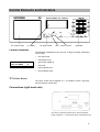
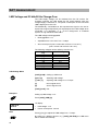
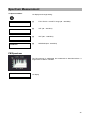
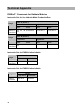
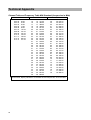
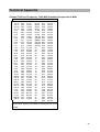
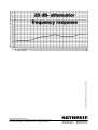
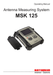
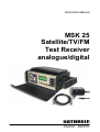
Instruction Manual MSK 25 Satellite/TV/FM Test Receiver analogue/digital Preface Preface Dear customer, The KATHREIN-Werke KG has done its utmost to guarantee the correctness and completeness of this manual. However, no liability can be assumed for any potential errors in this manual and any damages thereby resulting. This manual may not be copied or else be duplicated, neither as a whole, nor in extracts, without the written consent of the KATHREIN-Werke KG. This manual is subject to modifications and amendments without prior notice. This in particular applies to modifications which suit the technical progress. All product names and trademarks in this manual are the property of the respective firms. All rights reserved. Validity: This manual applies for the MSK 25. Date of issue: Sept. 2005 . 2 Contents Contents Preface.............................................................................................................................................................. 2 Contents ........................................................................................................................................................... 3 General Information......................................................................................................................................... 5 Signs and Symbols ........................................................................................................................................ 5 Safety Rules................................................................................................................................................... 5 Functionality .................................................................................................................................................... 6 Overview of Functions .................................................................................................................................... 7 Technical Data ................................................................................................................................................. 9 Control Elements and Indicators ................................................................................................................. 11 Control Elements.......................................................................................................................................... 11 TFT Colour Screen ................................................................................................................................... 11 Connections (right hand side) ...................................................................................................................... 11 Short Cut Overview ....................................................................................................................................... 12 Connections ................................................................................................................................................... 13 RF Input Socket ........................................................................................................................................... 13 External DC Voltage Supply ........................................................................................................................ 13 Scart Output ................................................................................................................................................. 13 RS 232 Interface .......................................................................................................................................... 13 Commissioning.............................................................................................................................................. 14 Switching-Up ................................................................................................................................................ 14 Switching-Off................................................................................................................................................ 14 Setup-Menu.................................................................................................................................................. 15 Factory Setting on Delivery ...................................................................................................................... 15 Setup Menu Setting .................................................................................................................................. 15 Setup Menu Call-Up ............................................................................................................................. 15 Mains Operation and Battery Operation ...................................................................................................... 16 Mains Operation ....................................................................................................................................... 16 Battery Operation ..................................................................................................................................... 16 SAT measurement ......................................................................................................................................... 17 Standard Change-Over ................................................................................................................................ 17 Frequency Display and Frequency Entry..................................................................................................... 18 SAT Menu Frequency Entry ..................................................................................................................... 18 SAT Analogue Level Measurement ............................................................................................................. 19 Level Overflow and Level Underflow........................................................................................................ 19 SAT DVB-S Level Measurement ................................................................................................................. 19 Locating Satellites ........................................................................................................................................ 20 Bearing for Individual Reception Frequencies ............................................................................................. 21 SAT Analogue Sound Carrier Frequency .................................................................................................... 22 DVB-S MER, BER and Offset Measurement............................................................................................... 23 MPEG Picture Representation (option) in DVB-S........................................................................................ 23 LNB Voltage and 22 kHz/60 Hz Change-Over ............................................................................................ 24 DiSEqC™ (Digital Satellite Equipment Control) .......................................................................................... 26 Framing Byte Menu .................................................................................................................................. 27 Address Byte Menu .................................................................................................................................. 28 Command Byte Menu............................................................................................................................... 29 Data Byte Menu........................................................................................................................................ 31 Simple Tone Burst DiSEqC™ ...................................................................................................................... 31 TV measurement............................................................................................................................................ 32 Standard Change-Over ................................................................................................................................ 32 DVB-C/DVB-T Change-Over ....................................................................................................................... 33 Channel display and channel entry.............................................................................................................. 34 Frequency Display and Frequency Entry..................................................................................................... 35 Level Measurement TV Analogue................................................................................................................ 36 Level Overflow and Level Underflow........................................................................................................ 36 TV/DVB-C/DVB-T Level Measurement........................................................................................................ 36 Bearing for Individual Reception Frequencies ............................................................................................. 37 Sound Carrier Distance and Sound Carrier Level ....................................................................................... 38 NICAM Sound Bit Error Rate Measurement ................................................................................................ 39 DVB-C/DVB-T (option), MER, BER and Offset Measurement..................................................................... 40 3 Contents MPEG Picture Representation (option) in DVB-C or DVB-T (option) .......................................................... 40 FM measurement ........................................................................................................................................... 41 Frequency Indication and Frequency Entry ................................................................................................. 41 Level Measurement...................................................................................................................................... 42 Level Overflow and Level Underflow........................................................................................................ 42 Bearing for Individual Reception Frequencies ............................................................................................. 43 Spectrum Measurement................................................................................................................................ 44 SAT Spectrum.............................................................................................................................................. 44 TV Spectrum ................................................................................................................................................ 44 FM Spectrum................................................................................................................................................ 45 Maintenance ................................................................................................................................................... 46 Changing the Battery ................................................................................................................................... 46 Customer Service ..................................................................................................................................... 46 Technical Appendix....................................................................................................................................... 47 Signal-to-Noise-Ratio ................................................................................................................................... 47 DiSEqC™ Commands for Kathrein Matrices ............................................................................................... 48 Instruction Set for 9xx Kathrein Matrix Production Run ........................................................................... 48 Instruction Set for EXR 20 Kathrein Matrix .............................................................................................. 48 Instruction Set for EXR 22 Kathrein Matrix .............................................................................................. 48 Channel Tables ............................................................................................................................................ 49 Channel Table and Frequency Table B/G Standard (frequencies in MHz).............................................. 49 Channel Table and Frequency Table L Standard (frequencies in MHz).................................................. 50 Channel Table and Frequency Table D/K Standard (frequencies in MHz).............................................. 51 Channel Table and Frequency Table I Standard (frequencies in MHz)................................................... 52 Channel Table and Frequency Table M1 Standard (Japan) (frequencies in MHz) ................................. 53 Channel Table and Frequency Table M/N Standard (frequencies in MHz) ............................................. 54 Channel Table and Frequency Table M/N Standard (frequencies in MHz) ............................................. 55 4 General Information General Information This user manual has been compiled for persons with some electrical engineering ability and knowledge. Users who have already operated similar measuring instruments can obtain the necessary commands for each operating step from the overview. In addition, the following examples will help you understand each operating step. Signs and Symbols Always adhere to the instructions classified with the warning signal carefully, as otherwise the MSK 25 test receiver may be damaged or even be destroyed. ☞ ✐ À This symbol provides information on measuring functions and refers to chapters containing further particulars on a subject. This symbol is followed by an example of the measuring function explained. Find an overview of the commands for the germane short cut for the particular measuring function. [key] Key on the instrument to be pressed. Safety Rules Careful observance of the VDE safety instructions is essential! Only fuses with the same power-down characteristics are to be used! On feeding in signals, heed the allowable peak levels! • HF input: max. 120 dBµV (60 dBmV)! • Do not connect direct-current (DC) voltage to the RF socket! Do not connect low frequency alternating-current (AC) voltage to the RF socket! The instrument is also energised when disconnected! Use only the power supply unit provided for voltage feed! Depending on the programming, between 5 V and 20 V may be connected to the RF input socket. From 10 V to 20 V, up to 500 mA can be obtained from the source, and up to 100 mA can be obtained from 5 V to 9.9 V. Additionally included in Delivery 1 Wall power supply 1 BNC measuring cable 1 Adapter BNC socket – F socket 1 Adapter BNC socket – F plug 1 Adapter BNC socket – IEC socket 1 Adapter BNC socket – IEC plug 1 20 dB attenuation plug with d.c. voltage passage (Find indications on the frequency response of the enclosed attenuation plug on the last page) Electronic equipment is not household waste - in accordance with directive 2002/96/EC OF THE EUROPEAN PARLIAMENT AND THE COUNCIL of 27th January 2003 on used electrical and electronic equipment, it must be disposed of properly. At the end of its service life, take this unit for disposal at a relevant of. cial collection point. 5 Functionality The MSK 25 has been conceived as a portable test receiver for TV, SAT and FM radio measurements, as well as for DVB-C, DVB-S and DVB-T in both, battery operation and mains operation. The built-in lead battery (3.4 Ah) and a wall power supply with a built-in charger, suitable for 230 VAC, are included in delivery. Controlling and scanning of the console and the display of frequency and level on the LCD are carried out by a microcontroller. The receiving frequency is indicated in MHz. Levels are measured with a peak value detector or with an average value detector and indicated digitally in dBµV or dBmV. Correction values are determined when the levels are calibrated for the MSK 25 and stored in EEPROM. Thus, precise level measurement readings can be recorded. A bargraph display is provided to help locate transmitters. In addition, a level-dependent acoustic signal facilitates the antenna alignment. The display need not be observed. The audio part with its built-in loudspeaker can process and reproduce the various Sat and TV-NF signals complying with the B/G, D/K, I, M1 (JAPAN) and M/N standards, as well as with the FM audio signals and the DVB-C-, DVB-T- and DVB-S signals (if the intrument provides MPEG or DVB-T respectively). NICAM and AM sound reproduction (L standard) is also possible. The LNB supply voltage of 20 V /, max. 500 mA, with a graduation of 0.1 V, as well as the superimposition of 22 kHz / 60 Hz and the option to send DiSEqC™ commands or Simple-DiSEqC™commands, cover all currently known specifications. In DVB-T mode, you can obtain antenna feed voltage between 5 V and 9.9 V, max. 100 mA, from the RF socket. The built-in TFT colour screen allows the screening and evaluation of analogue TV and SAT signals on the spot. If MPEG option is provided, also digital signals can be displayed. * * * * Spectrum display Loudspeaker for acoustics control Multiple standards reception (B/G, D/K, I, L, Nicam, M/N, M1) Nicam audio reception and L standard Sound storage medium setting * * 22 kHz / 60 Hz change-over DiSEqC™, Simple DiSEqC™ Nicam tone, reception and bit error rate measurement * Option MPEG * (audio ) Scart output (video and audio) * Option MPEG DVB displaying * DVB-MER-BER measurement * * * QPSK Option MPEG * * * * DVB-S mode * * * * * * * * * Analogue FM mode DVB level measurement * * * LNB external feeding power supply tunable LNB external feeding current measurement * * Sound storage medium measurement * * * * * * Level-dependent acoustic signal * * * Level measurement by frequency setting * Analogue TV mode Level measurement by channel setting * Analogue SAT mode Mains operation and battery operation Function Overview of Functions Overview of Functions Option MPEG Option MPEG * * * * * QAM 64, QAM 128 Option MPEG * * * * * DVB-C mode 7 Option MPEG Option MPEG * * * * * COFDM 2k, 8k Option MPEG * * * * * Option DVB-T mode 8 LNB 0/5 - 20 V Technical Data Technical Data Power supply Mains operation Battery operation 230 VAC, 50/60 Hz Lead Battery 12 V/3.4 Ah Dimensions Width 260 mm, Height 90 (120) mm, Depth 165 mm incl. accessories (plus case) Weight ca. 4.5 kg (incl. case) Safety standards CE mark Protection class II VDE EN 61010 Display Temperature range Frequency range TFT screen, LCD alpha numeric, 2x16 characters, Bargraph display, backlit SAT TV FM Channel configuration +5 C to +45 C 920 MHz...2150 MHz 48 MHz...858 MHz 88 MHz...108 MHz (48 MHz...858 MHz) TV D/G/I/K standard M/N/M1 standard Frequency tuning SAT TV FM 0.125 MHz graduations 50 kHz graduations 50 kHz graduations Measurement error SAT TV/FM Max. ±2 dB Max. ±2 dB B standard 8 MHz 6 MHz RF input BNC 75 Ω coaxial socket RF input reducer 0 – 60 dB in 4 dB graduations Level measurement range 30–120 dBµV Measurement bandwidth Measuring detector SAT SAT DVB TV FM 6 MHz 6 MHz 250 kHz 250 kHz SAT TV FM Average value display Maximum value display Average value display Voltage standing wave ratio TV/DVB 7 MHz 6 MHz > 6 dB FM threshold SAT < 9 dB Audio-IF bandwidth SAT TV FM 230 kHz/150 kHz 230 kHz 230 kHz Audio Deemphasis SAT TV/FM 50 µs 50 µs Audio processing SAT FM audio processing 5.0 MHz…8.99 MHz in 10-kHz graduations TV FM and Nicam in quasi-parallel audio mode AM in parallel audio mode (L standard only) 9 Technical Data TV B/G standard D/K standard I standard M/N standard M1 standard L standard B/G standard I standard TT1 = 5.5 MHz, TT2 = 5.74 MHz TT1 = 6.5 MHz, TT2 = 6.26 MHz TT1 = 6.0 MHz TT1 = 4.5 MHz, TT2 = 4.72 MHz TT1 = 4.5 MHz AM 6.5 MHz, Nicam = 5.85 MHz Nicam = 5.85 MHz Nicam = 6.552 MHz FM FM audio processing 48 MHz...858 MHz Sound carrier measurement TV D/K standard I standard L standard M/N standard M1 standard Nicam decoder Sound carrier distance TV 5.58 MHz with B/G, D/K, L standards 6.552 MHz with I standard Nicam BER TV DVB-S modulation method1) 0-4 x 10⁻² QPSK 1) 64 QAM, 128 QAM, DOCSIS 64 QAM (MER and Offset only) 1) OFDM, 2k, 8k, QPSK, 16 QAM, 64 QAM (Option) DVB-C modulation method DVB-T modulation method Standard B/G 5.5 MHz, 5.74 MHz, 5.85 MHz 6.5 MHz, 6.26 MHz 6.0 MHz, 6.552 MHz 6.5 MHz, 5.85 MHz 4.5 MHz, 4.72 MHz 4.5 MHz DVB-S-MER1) -20 dB DVB-C-MER1) -32 dB DVB-T-MER1) -32 dB DVB-S-BER pre-Viterbi1) 0 – 2.8 x 10⁻² DVB-C-BER pre-Reed Solomon1) 0 – 2.8 x 10⁻² DVB-T-BER pre-Viterbi1) 0 – 2.8 x 10⁻² (Option) (Option) DVB-S carrier-offset-measurement1) DVB-C carrier-offset-measurement1) DVB-T carrier-offset-measurement1) (Option) LNB supply voltage External feeding voltage SAT TV 0, 10 V...20 V, max. 500 mA 0, 5 V...9.9 V, max. 100 mA LNB control SAT 22 kHz, 60 Hz, DiSEqC™, Simple DiSEqC™ SCART output 1 Vpp/75 Ohm 1) For measuremts exceeding 100 dBµV please use the enclosed attenuation plug, as otherwise no video representation and no MER and BER measurements are possible. 10 Control Elements and Indicators Control Elements and Indicators TFT colour screen LC display HF input socket LED volume control Keyboard Control Elements The following is displayed on the two-row 16 digit LC display, depending on the mode: FR: 954.0 MHz LEV: 40.0 dBuV SAT D • the channel set, • the frequency set, • the function called up, • the mode, • the measured level • the measured value TFT Colour Screen The colour screen has a diagonal of 4“, a resolution of 238 x 480 pixel, and a luminance of 250 cd/m². Connections (right hand side) (AV) Scart connections without inputs, RS 232 interface,, supply voltage DC – for the power supply unit delivered only 11 Short Cut Overview Short Cut Overview Key SAT/TV Brief description of the various functions SAT/DVB-S TV/DVB-C/*DVB-T FM Change-over to Change-over Change-over to TV reception SAT reception TV reception - Diminish current values + Elevate current values 0-9 Numeric character entry ./S Decimal point for • numeric character entry • Decimal point for Decimal point for numeric character input numeric character input Special channel call up ENTER Confirm numeric character entry 2ndF + key Call-up of the second command level FM Sat-Ctrl Change-over to FM Call-up of DiSEqC™ menu / Menu / Remote feeding LNB LNB Call-up of DiSEqC™ menu / remote feeding LNB voltage menu and Remote feeding voltage and Remote feeding voltage current measurement current measurement and current measurement • Call-up of frequency menu • Ch-Freq No function Change-over from channel display to No function frequency display and reverse Std DVB-S/analogue change-- DVB-C/*DVB-T/analogue- over change-over No function standard-change-over DVB DVB-S measurement DVB-C-/*DVB-T MER, BER, OFFSET measurement *MPEG programme MER, BER, OFFSET selection *MPEG programme No selection SC Scan (Subcarrier) sound carrier menu, sound carrier measurement No function Frequency-independent No function No function satellite search Level ♫ Switch-on level-dependent acoustic signal with bargraph display Spect Spectrum analysis Setup Adjustment of instrument settings * only if option is provided 12 Connections Connections RF Input Socket The received signal of the antenna or of the cable network is fed in here (BNC coaxial socket). The remote feeding voltage (for LNB) is adjustable from 5 VDC to 20 VDC and can be switched off. When the LNB voltage is switched on, the LED next to the RF input socket flashes. Make sure that there are • no voltage level over 120 dBµV, • no positive DC voltage over 22 VDC, • no negative DC voltage and • no AC voltage adjacent to the RF input socket. Non-compliance with these warning notices may destroy the input circuit. External DC Voltage Supply The MSK 25 may either be mains operated or battery operated (batteries built-in). The external voltage supply is carried out via the DC socket at the right side of the MSK 25 box, with the wall power supply and the charger, both included in delivery. Sustained continuous operation (incl. MPEG option) is possible in case of an LNB power consumption of no more than max. 300 mA. Additional current will be drained from the battery built-in if the power consumption is higher than that. Make sure that • only the wall power supply included in delivery is used. • the wall power supply is not connected to the instrument but for voltage feed. Otherwise the battery of the MSK 25 will be discharged! Scart Output The video and audio signals are emitted on the Scart socket on the right hand side of the MSK 25, for rating purposes on an external monitor. There are no inputs! Misallocations of the connections may cause damage or destruction of the instrument! RS 232 Interface Software updates are possible via RS 232 interface. 13 Commissioning Commissioning Switching-Up Software V2.0 SN: 000222 ACCU • Connect the instrument to the mains with the wall power supply. • Turn the on/off switch to the right. • Adjust the desired volume. The LC display will then indicate the particular software version for appr. 1 second. [−−−−−] Thereafter the LC display will indicate the loading capacity of the battery for appr. 3 seconds. One segment comes up to appr. 20% of the overall capacity (3.4 Ah). Now, feed in the reception signal of the receiving installation in the RF input socket. LC display: CH: .02. LEV: 48.5dBuV TV A • channel • mode • level (A = analogue level measurement; D = digital level measurement) Select the desired mode by pressing [TV/SAT] Switching-Off Turn the on/off switch counter-clockwise. 14 Commissioning Setup-Menu The basic setting (status of the MSK 25 after switching it on) can be set in the Setup menu. Factory Setting on Delivery Parameter POWER ON LNB DC LEVEL Low Level Mute Setting TV OFF dBµV ON Setup Menu Setting Setup Menu Call-Up Press [2ndF] and [SETUP]. The particular mode (TV, SAT, FM) is selected and taken-over by pressing either [1], [2] or [3]. The current setting is retained by pressing [ENTER.] POWER ON 1=TV 2=SAT 3=FM 1. Setup menu The following requests appear: LNB DC 1=OFF 2=ON Press either [1] or [2] to switch on/off the LNB voltage supply. Press [ENTER] to retain the current setting. 2. Setup menu Level 1=dBµV 2=dBmV Press either [1] or [2] to determine the measurement unit the level is to be displayed with. Press [ENTER] to retain the current setting. 3. Setup menu LOW LEVEL MUTE 1=OFF 2=ON Set or offset the mute function by pressing either [1] or [2]. Select „ON“ to mute the MSK 25 until the input signal on the RF input exceeds 30 dBµV. 4. Setup menu Press [ENTER] to retain the desired setting. CH: .07. LEV:____.__dBµV TV Unless the factory settings have been changed, the indication opposite is displayed. Basic setting After setting the Low Level Mute, the 4th Setup menu will be exitted automatically and the basic setting will be displayed. 15 Commissioning Mains Operation and Battery Operation The MSK 25 may either be mains operated or be battery operated (battery built-in). Mains Operation Only the wall power supply delivered may be used for power supply. Connect it to the voltage supply socket on the right hand side of the instrument. Sustained continuous operation (incl. MPEG option) is possible in case of an LNB power consumption of no more than max. 300 mA. Additional current will be drained from the battery built-in if the power consumption is higher than that. In case of any longer-lasting placing-out-of-operation, connect the MSK 25 to the mains supply occasionally (trickle charge). Make sure that the wall power supply is not connected to the instrument but for voltage feed. Otherwise the battery of the MSK 25 will be discharged! Battery Operation Battery operation is only possible if the battery is sufficiently charged. Otherwise the MSK 25 cannot be switched on. When completely discharged, the battery must immediately be recharged, since otherwise it may be damaged or destroyed. Charging begins automatically as soon as the instrument has been connected to the mains supply. Battery supercharge is avoided with a protective circuit. When switching on the MSK 25, the loading capacity of the battery is indicated for appr. 3 seconds. The maximum operating time with a fully charged battery is appr. 2.5 hrs, in case of an LNB supply current of 150 mA. 16 SAT measurement SAT measurement Standard Change-Over In SAT mode, the MSK 25 receives • analogue signals and • DVB-S signals. SAT Menu Standard Change-Over [2ndF] [STD] À [1] to [2] calling up menu standard change-over: select standard 1 = analogue 2 = digital (DVB-S) Examples ✐ Calling up DVB-S standard 1=ANALOGUE 2=DVBS • 1 = analogue standard • 2 = digital (DVB-S) standard Press [2ndF] [STD] The LC display indicates the following options: When selecting ‚2‘ you will get to the symbol-rate-selection The LC display indicates the following options: 1=27500 3=22000 2=24500 4= USER Under the position 4=USER you can enter sample rates from 1,500 up to 32,000 ks and close with ENTER. Standard menu FR:1288.0MHz LEV: 66.5dBuV SAT D When you have selected an option, you will leave the standard menu and the instrument will be set to DVB measurement. The display indicates ‘D’. Display for DVB-S measurement 17 SAT measurement Frequency Display and Frequency Entry To measure the level of a received signal, you must first enter the frequency required. The LC display indicates the frequency and the level measured. Frequency entry is possible from 920 MHz to 2150 MHz in 100 kHz steps. ☞ SAT Menu Frequency Entry [SAT/TV] Changing over to SAT reception À [0] to [9] Entering frequency [+] [-] Varying frequency in 100 kHz steps [ENTER] Confirming your entry FR:1288.0MHz LEV: 66.5dBuV SAT A │ LC display: • Frequency: 1288 MHz • Mode: SAT • Level: 66.5 dBµV A (A = analogue) Example Enter the frequency 1508 MHz by pressing [1] [5] [0] [8] [ENTER] ✐ FR:1508.0MHz LEV: 86.5dBuV LC display: SAT A │ • frequency: 1508 MHz • mode: SAT • level: 86.5 dBµV (A = analogue) The indicaton „+“ or „–“ on the display means that the MSK 25 has not been exactly tuned to the carrier required. Bei pressing either [+] or [-], the frequency can be finetuned for optimum reception. This has been achieved when a vertical line appears on the display. Note ☞ 18 Press [ENTER] to complete the frequency entry. The last frequency entry will be retained even after you have switched off the MSK25, provided that the entry was carried out via numeric character input ending with ‚MHz‘ SAT measurement SAT Analogue Level Measurement Once you have entered a frequency, the level is measured automatically and displayed either in dBµV or dBmV (depending on the basic configuration) on the LC display. The input level can be measured in the range of 30 dBµV to 120 dBµV (-30 dBmV to 60 dBmV). LC display: FR:1508.0MHz LEV: 86.5dBuV SAT A │ • Frequency: 1508 MHz • Mode: SAT • Level measured: 86.5 dBµV A Level Overflow and Level Underflow FR:1508.0MHz LEV: __._dBuV FR:1508.0MHz LEV: ¯¯˙¯dBuV SAT A │ SAT A │ The LC display indicates underflow at a level of < 30 dBµV. The following indications appear on the display: • frequency: 1508 MHz • mode: SAT • level: underflow The LC display indicates overflow at a level of > 120 dBµV. The following indications appear on the display: • frequency: 1508 MHz • mode: SAT • level: overflow Note DVB-S signal levels can only be measured when the digital reception is set. ☞ SAT DVB-S Level Measurement LC display when the DVB-S level is measured: The change-over from the analogue measurement to the digital level measurement is described in chapter ‚standard change-over‘ FR:1236.0MHz LEV: 86.5dBuV SAT D • Frequency 1236 MHz • Mode: SAT DVB-S • Level measured: 86.5 dBµV D 19 SAT measurement Locating Satellites With the SCAN function, satellites, the exact transponder frequencies of which are unknown, can be located. In doing so, the frequency range from 1000 MHz to 2100 MHz is continuously scanned for received signals. If signals are received, the reception level is displayed as a bar graph. The measurement range may be adjusted to three different sensitivity levels. The level can be monitored with an acoustic signal, the pitch of which is proportional to the received-signal level. The volume of the acoustic signal can be adjusted with the volume regulator. SCAN Menu [2ndF] [SCAN] Changing over to SCAN mode À [-] [+] Change-over of the bar graph measurement range. Level range 1: high input levels Levelrange 2: medium input levels Level range 3: low input levels [2ndF] [2ndF] Exit LC display: LEV-Range:2 > ■■■■ SAT • Level range 2: medium input level • SAT mode • Bargraph display Example ✐ Calling up SCAN mode: • Press [2ndF] [SCAN]. • Move the antenna until there is a level tendency visible on the bargraph display. • Move the antenna until the maximum amplitude on the bargraph display is reached. • If necessary, diminish or elevate the sensitivity by pressing either [-] or [+]. Exit: • Press [2ndF] twice. 20 SAT measurement Bearing for Individual Reception Frequencies The „LEVEL ♫“ function allows the antenna alignment to maximum received signal via bearing. The level tendency can be bargraphdisplayed.The measurement range can be adjusted to three different sensitivity levels. The level can be monitored with an acoustic signal, the pitch of which is proportional to the received-signal level. The volume of the directional radio audio signal can be adjusted with the volume regulator. Bearing Menu [2ndF] [LEVEL ♫] Changing over to bearing mode: À [-] [+] Change-over of the measurement range of the bar graph. The measurement range is automatically preselected. Level range 1: high input levels Level range 2: medium input levels Level range 3: low input levels [2ndF] [2ndF] Exit LC display: LEV-Range:2 > ■■■■ SAT • Level range 2: medium input level • Mode: SAT • Bargraph display Example Calling up „LEVEL ♫“ mode ✐ Press [2ndF] [LEVEL♫]. Move the antenna until the maximum amplitude of the bargraph display is reached. If necessary, diminish or elevate the sensitivity by pressing either [-] or [+] . Repeat this procedure until the maximum level is reached. Exit: Press [2ndF] twice. 21 SAT measurement SAT Analogue Sound Carrier Frequency Each video signal has several sound carrier frequencies assigned to it. Selective hearing of the sound maincarriers and the sound subcarriers is possible. The sound carrier frequency is tunable from 5.0 MHz to 8.99 MHz in 10 kHz steps. The soundcarrier bandwidth is automatically changed over from wide (280 kHz) to narrow (150 kHz) at 7.00 MHz. The following sound carrier frequencies are factory-set: key [1] [2] [3] [4] [5] [6] [7] [8] [9] Frequency in MHz 5.80 6.50 6.65 7.02 7.20 7.38 7.56 7.74 7.92 Bandwidth in kHz 280 wide 280 wide 280 wide 150 narrow 150 narrow 150 narrow 150 narrow 150 narrow 150 narrow SAT Sound Carrier Frequencies Menu À [2ndF] [SC] Calling up sound carrier menu [1] to [9] Selecting sound subcarrier (see table above) [-] or [+] Varying sound carrier frequency in 10 kHz steps [ENTER] Manually changing over sound carrier band width wide = 280 kHz, narrow = 150 kHz [2ndF] [2ndF] Exit Example Retrieving sound carrier 7.38 MHz: ✐ SC: 7,38MHz BW:NARROW Press [2ndF] [SC] [6] LC display: SAT • Sound subcarrier: 7.38 MHz • Sound carrier bandwidth: narrow = 150 kHz • Mode: SAT Note ☞ 22 After SAT mode has been called up, the MSK 25 will be permanently adjusted to sound carrier 7.02 MHz. Frequency variations of the sound carrier will not be retained after SAT mode has been closed. SAT measurement DVB-S MER, BER and Offset Measurement The modulation error rate (MER), the bit error rate (BER) and the carrier offset can be measured to rate the digital reception quality. Chapter ‚standard change-over‘ describes how to select between SAT/analogue and DVB-S. Calling up DVB-S measurement: Press [2ndF] [DVB] in SAT reception mode LC display: MER:12.6dB BER:1.7e-7 MHz + 0.72 • (MER) modulation error rate: 12.6 dB • (BER) bit error rate: 1.7e-7 • Carrier offset +0.72 MHz In case there are no bit errors identified due to a strong DVB signal, BER=0.0e+0 is indicated on the display. MPEG Picture Representation (option) in DVB-S After selecting DVB measurement by pressing [2ndF] [DVB], the list of programmes received via digital transport data stream is displayed on the TFT screen. Press [+] or [-] to select the desired programme and confirm your entry by pressing [Enter]. In case of an FTA programme, picture and sound of the desired programme are decoded and represented or reproduced respectively via the loudspeaker which is built in. Select another programme on the list by pressing [Enter] once more. Press [2ndF] to exit digital reception. Note ☞ For measuremts exceeding 100 dBµV please use the enclosed attenuation plug, as otherwise no video representation and no MER and BER measurements are possible. (Find indications on the frequency response of the enclosed attenuation plug on the last page) 23 SAT measurement LNB Voltage and 22 kHz/60 Hz Change-Over The LNB supply voltage can be obtained from the RF socket. For checking purposes, the LED beside the RF socket flashes when the voltage supply is switched on. The power consumption of the connected LNB is displayed on the LCD. The additionally connectable 22 kHz square-wave signal or the 60 Hz square-wave signal respectively will superimpose the LNB voltage when connected. It is necessary, e. g., for the change-over of multifeed systems or high band/low band LNB’s. The LNB voltage is disengageable. • Disengageable = 0 V • Adjustable from 5 V to 20 V in 0.1 V steps • Short-circuit proof (max. current 500 mA from 10 V to 20 V) (max. current 100 mA from 5 to 9.9 V) The following voltages can be called up via short cut: key [0] [1] [2] [3] [5] LNB voltage [7] [8] 60 Hz 22 kHz 0V 12 V 14 V 18 V 5V LNB Voltage Menu À [2ndF] [LNB] Calling up LNB menu [0] bis [5] Selecting LNB voltage [-] oder [+] Adjusting LNB voltage in 0.1 V steps [7] 60 Hz signal on/off [8] 22 kHz signal on/off [2ndF] [2ndF] Exit Examples ✐ Calling up LNB voltage 14 V: Press [2ndF] [LNB] [2] LC display: LNB:14,0V 150mA • LNB voltage: 14 V • Power consumption: 150 mA Note ☞ 24 Press [+] or [-] to adjust the LNB voltage in 0.1 V steps. By calling up a different function, e.g. [2ndF] [CH-FRQ], the LNB menu will be closed automatically. SAT measurement Example ✐ Activating the 22 kHz signal: Press [2nF] [LNB] [8] LC display: LNB:14,0V 150mA 22kHz • LNB voltage: 14 V • Power consumption: 150 mA • 22 kHz signal activated Note By pressing [8] again, the 22 kHz signal can be deactivated. ☞ By calling up a different function, e. g. [2ndF] [CH-FRQ] or 2x [2ndF], the LNB menu will be closed automatically. 25 SAT measurement DiSEqC™ (Digital Satellite Equipment Control) The DiSEqC™ system is used for control systems with extended control facilities. DiSEqC™ utilises a serial, bidirectional transmission mode with one master and one or more slaves. The data bits are generated with pulse width modulation of the 22 kHz carrier already existent, and are superimposed with 600 mVpp of the LNB remote feeding voltage. The digital code words are composed of 8 data bits and one additional parity bit for the recognition of transmission errors. Several code words generate a DiSEqC™ command. The code word entry is to be effected in the hexadecimal code. Code-Wörter Framing P Address P Command P Data P Paritätsbit MSK 25 can emit signals to DiSEqC™1.0, however, it cannot receive signals. DiSEqC™ Menu [2ndF] [SAT-CTRL] Calling up DiSEqC™ menu À You will find the main DiSEqC™ commands for four satellite positions and the respective allocations of high and low band, as well as their appendant horizontal polarisation or vertical polarisation, displayed on the TFT screen. [0] USER entry [1] bis [8] Selection of the desired DiSEqC™ command [9] Further DiSEqC™ commands or Simple DiSEqC™ commands [ENTER] Sending the selected command string USER entry [0] to [9] Code word entry in hexydecimal code 0 to 9 [.] [0] to [5] Code word entry in hexadecimal code A.to.F [-] or [+] key Hexadecimal code [.] [0] A [.] [1] B [.] [2] C [.] [3] D [.] [4] E [.] [5] F Moving the cursor to the indivdual code words: Framing, Address, Command and Data [.] [6] Deleting the entire command string up to the cursorposition [ENTER] Sending the command string [2ndF] [2ndF] Exit 26 SAT measurement ✐ DiSEqC- Example for a USER entry You wish to check the EXR 22 KATHREIN matrix. The instruction set for the EXR 22 matrix is E0 00 24 (LNB High) and E0 00 20 (LNB Low). Calling up DiSEqC™: Press [2ndF] [SAT-CTRL] Press [0] to call up USER entry. SAT-CTRL menu DiSEqC-Framing E■ You can now enter the indvidual code words by pressing [0] to [9] and [./S]. Press [ENTER] to send the command. „>“ signalises the successful sending of the command. DiSEqC™ menu DiSEqC-COMMAND E0 00 24 > The instruction set to trigger the EXR 22 KATHREIN matrix has been entered and sent. DiSEqC™ menu Note ☞ Please find the DiSEqC™ instruction sets for KATHREIN matrices, Types EXR 20 and EXR 22 and for the 9xx production run in the technical appendix. Framing Byte Menu À HEX Byte E0 E1 E2 E3 E4 E5 E6 E7 description Command from master, nonrecurring transmission Command from master, recurrent transmission Command from master, response anticipated, first transmission Command from master, response anticipated, recurrent transmission Response from slave, „OK“, no errors recognised Response from slave, command not supported by slave Response from slave, parity error recognised Response from slave, command not identified 27 SAT measurement Address Byte Menu À Hex Byte 00 10 11 12 14 15 18 20 21 22 30 31 32 33 34 40 41 60 70 71 Fx 28 Description All instruments Every LNB, Matrix or SMATV LNB LNB with loop-through Matrix (Switcher) Matrix (Switcher) with loop-through SMATV Every polarizer Maximum turning (full skew) in linear polarisation Stepwise polarizer adjustment Every positioner Polar/Azimuth positioner Elevation positioner Combined positioner LNB Positioner Set up help Signal strength setting help Reserved for assigned addresses „Intelligent slave interface“ for „Proprietary MultiMaster bus“ Interface for users and controlled head-end OEM expansion SAT measurement Command Byte Menu MSK 25 can send commands under DiSEqC™ 1.0 but cannot receive them. All the commands requiring DiSEqC™ 2.0 (sending and receiving) are underlined grey in the table below. À Hex Byte Commands in bold are particularly preferred for KATHREIN switching matrices. Command Description 00 01 02 03 04 05 06 07 08 09 10 11 14 15 16 17 20 21 Reset Clr Reset Stand-by Power on Set Contend Contend Clr Contend Adresse Move C Move Status Config Switch 0 Switch 1 Switch 2 Switch 3 Set LO Set VR 22 23 24 25 Set Pos A Set S0A Set Hi Set HL 26 27 28 29 2A 2B 2C 2D 2E 2F 30 31 38 39 3A 3B 40 41 48 49 Set Pos B Set S0B Set S1A Set S2A Set S3A Set S4A Set S1B Set S2B Set S3B Set S4B Sleep Awake Write N0 Write N1 Write N2 Write N3 Read A0 Read A1 Write A0 Write A1 Reset DiSEqC™ Microcontroller Delete reset flag Switching off peripheral power supply unit Switching on peripheral power supply unit Adjustment of contention flag Feedback only if contention flag has been set Delete contention flag Feedback only if contention flag has not been set Change address when contention flag has been set Change address when contention flag has not been set Read status register flags Read configuration flags Read switching status flags (Committed Port) Read switching state flags (Uncommitted Port) Expansion option Expansion option Calling up of low local oscillator frequency Calling up the vertical polarisation or clockwise circular polarisation Select satellite position A Select switchoption A Calling up of high local oscillator frequency Calling up of horizontal polarisation or counter-clockwise circular polarisation Select Satellitenposition B Select switchoption B Calling up of matrix S1 input A (input B inactive) Calling up of matrix S2 input A (input B inactive) Calling up of matrix S3 input A (input B inactive) Calling up of matrix S4 input A (input B inactive) Calling up of matrix S1 input B (input A inactive) Calling up of matrix S2 input B (input A inactive) Calling up of matrix S3 input B (input A inactive) Calling up of matrix S4 input B (Eingang A inactive) All bus commands ignored, except „Awake“ Bus commands again accepted Setting Port Group 0 Setting Port Group 1 Expansion option Expansion option Read analogue value A0 Read analogue value A1 Set analogue value A0 Set analogue value A1 Numbe r of data bytes 1 1 1 1 1 1 1 1 29 SAT measurement 4F 50 51 52 53 58 59 60 61 62 64 65 6C 6D 30 Write A7 LO string LO now LO Lo LO Hi Write Freq Ch.No. Halt Go E Go W P Status Read Pos Goto Write Pos Set analogue value A7 Read current frequency Read current frequency (Table Entry Number) Read Lo frequency table entry number Read Hi frequency table entry number Write channel frequency Set selected channel number (receiver) Stop positioner Move positioner eastward Move positioner westward Read positioner status register Read positioner counter Move positioner motor to counter value, Hi, Lo Set positioner counter, Hi, Lo 1 2 or 3 2 2 2 SAT measurement Data Byte Menu À A corresponding data byte need not be sent to a command byte unless required by the command byte data byte(s). You can see this from the preceding command byte table. Please learn from the data sheets of the respective instruments which data byte is to be sent to the particular command byte. Orbitposition 1 2 3 4 Switch setting H/V Switch setting LNB Data byte V V H H Lo Hi Lo Hi F0 F1 F2 F3 V V H H Lo Hi Lo Hi F4 F5 F6 F7 V V H H Lo Hi Lo Hi F8 F9 FA FB V V H H Lo Hi Lo Hi FC FD FE FF Simple Tone Burst DiSEqC™ A simplified version of the DiSEqC™ control is the Simple Tone Burst DiSEqC™ procedure. Simple DiSEqC™ allows two different switching states: Tone Burst and Data Burst. Simple DiSEqC™ Menu [2ndF] [SAT-CTRL] Call- up SAT–CTRL menu À [9] [9] Call-up Simple-DiSEqC™ menu [0] Tone Burst entry [1] Data Burst entry [ENTER] Sending of command string [2ndF] [2ndF] Exit 31 TV measurement TV measurement Standard Change-Over In TV mode, the MSK 25 can measure the following standards: • B/G standard • L standard • D/K standard • I standard • M/N standard • M1 standard (Japan) Standard Change-Over TV Menu À [2ndF] [STD] Calling up standard change-over menu [0] Addressing standard menu [0] bis [6] Selecting standard Example ✐ Calling upB/G analogue standard: Press [2ndF] [STD]. LC display: 1=ANALOG 3=DVBT 2=DVBC 0=Std. • 1 = Analogue reception • 2 = DVB-C reception • 3 = DVB-T reception (if this option is provided) • 0 = standard menu Press [0]. 1=BG 4=I 2=L 5=MN 3=DK 6=M1 The following menu is displayed: • 1 = B/G standard- 2 = L standard - 3 = D/K standard etc. Standard menu Press [1]. The instrument is now set for analogue reception in the B/G standard Note ☞ 32 Please note that the selected standard will be retained after the instrument has been switched off. TV measurement DVB-C/DVB-T Change-Over Press [2ndF] [STD]. LC display: 1=ANALOG 3=DVBT 2=DVBC 0=Std. • 1 = Analogue reception • 2 = DVB-C reception • 3 = DVB-T reception (if this option is provided) • 0 = Standard menu Press [2] to change over to DVB-C standard LC display: 1=QAM64 3=DOC64 2=QAM128 • 1 = QAM 64 demodulation • 2 = QAM 128 demodulation • 3 = DOCSIS QAM 64 demodulation Press [1] to set the QAM 64 symbol rate 1=6.900 3=6.875 2=6.952 4=USER LC display: • 1 = 6.900 MS • 2 = 6.952 MS • 3 = 6.875 MS • 4 = USER MS Select the corresponding symbol rate by pressing the corresponding key [1] [4]. The standard setting will then automatically be closed. 33 TV measurement Channel display and channel entry You first have to set the required channel to be able to measure the level of a TV reception signal. The following channels may be set: • Band /III CH 01 to CH 12 in 7 MHz raster • Band IV/V CH 21 to CH 70 in 8 MHz raster • Special channel S 02 to S 03 in 8 MHz raster • Special channel S 04 to S 20 in 7 MHz raster • Special channel S 21 to S 41 in 8-MHz raster This information applies only for the factory-set B/G standard. Please find more information on further standards in the technical appendix. TV Channel Setting Menu À [SAT/TV] Changing over to TV reception [0] bis [9] Setting channel [./S] Changing over to special channel [+] und [-] Varying channels stepwise Example ✐ CH:S.11. LEV: 62,5dBuV Setting channel S11: Press [./S] [1] [1]. LC display: TV A • Special channel: S 11 • Level: 62,5 dBµV • Mode: TV analog Note ☞ 34 Make sure that the correct standard has been set. B/G standard is factory-set. TV measurement Frequency Display and Frequency Entry You first have to enter the required picture carrier frequency to be able to measure the level of a TV reception signal. Frequency entry is possible from 48 MHz to 858 MHz in 50 kHz steps. TV Frequency Entry Mode À [SAT/TV] Changing over to TV reception [CH-FRQ] Change-over channel/frequency [0] bis [9] Entering frequency [ENTER] Confirming entry [+] und [-] Varying frequency stepwise Example Entering frequency 175.25 MHz: ✐ Press [2ndF] [CH/FRQ] .....................(frequency menu call up) Then press [1] [7] [5] [./S] [2] [5] [ENTER] ...........(frequency entry) LC display: CH:175,25 LEV: 65,0dBuV TV A • Frequency: 175.25 MHz • Level: 65.0 dBµV • Mode: TV analogue Note ☞ If you had called up the frequency menu before, you now only need to enter the figures in order to enter a frequency. The last frequency entry will be retained even after you have switched off the MSK 25, provided that the entry was carried out via numeric character input, ending with ‚MHz‘ 35 TV measurement Level Measurement TV Analogue After you have set a channel or a frequency, the level is automatically measured and displayed on the LC display either in dBµV or in dBmV (depending on the basic configuration). The input level can be measured in the range of 30 dBµV to 120 dBµV (-30 dBmV to 60 dBmV). LC display: CH: .05. LEV: 86.5dBuV TV A • Channel: CH 05 • Mode: TV analogue • Level measured: 86.5 dBµV Level Overflow and Level Underflow The LC display indicates underflow at a level of < 30 dBµV. LC display: CH: .05. LEV:___._dBuV TV A • Channel: CH 05 • Mode: TV analogue • Level: underflow The LC display indicates overflow at a level of > 120 dBµV. LC display: CH: .05. LEV:.dBuV TV A • Channel: CH 05 • Mode: TV analogue • Level: overflow Note DVB-C signals can only be measured if „digital reception“ has been set, see chapter ‚standard change-over‘. ☞ TV/DVB-C/DVB-T Level Measurement LC display when the DVB-C/DVB-T levels are measured: CH:S.32. LEV: 64.0dBuV 36 TV D The change-over from the analogue measurement to the digital level measurement is described in chapter ‘standard change-over’ • Channel: Special channel 32 • Mode: TV/DVB-C or DVB-T • Level measured: 64.0 dBµV D TV measurement Bearing for Individual Reception Frequencies The „LEVEL ♫“ function allows the antenna alignment to maximum received signal via bearing. The level tendency can be bargraphdisplayed. The measurement range can be adjusted to three different sensitivity levels. The level can be monitored with an acoustic signal, the pitch of which is proportional to the received-signal level. The volume of the directional radio audio signal can be adjusted with the volume regulator. Bearing Menu À [2ndF] [LEVEL ♫] Changing over to bearing mode: [-] [+] Change-over of the measurement range of the bar graph. The measurement range is automatically preselected. [2ndF] [2ndF] Level range 1: high input levels Level range 2: medium input levels Level range 3: low input levels Exit LC display: LEV-RANGE:2 > ■■■■ TV • Level range 2: medium input level • Mode: TV • Bargraph display Example ✐ Calling up „LEVEL ♫“ mode: Press [2ndF] [LEVEL ♫]. Move the antenna until the maximum amplitude of the bargraph display is reached. If necessary, diminish or elevate the sensitivity by pressing either [-] or [+]. Repeat this procedure until the maximum level is reached. Closing LEVEL mode: Press [2ndF] twice. 37 TV measurement Sound Carrier Distance and Sound Carrier Level On a second sound carrier, TV broadcast stations can transmit either frequency-modulated (analogue) or in Nicam format (digital). Depending on the standard which has been set, various frequencies are assigned to the sound carriers, see table. Sound carrier 1 is permanently set after the channel entry or frequency entry. Standard B/G D/K I M/N L M1 (Japan) TT1 5.5 MHz 6.5 MHz 6.0 MHz 4.5 MHz AM 6.5 MHz 4.5 MHz TT2 5.74 MHz 6.26 MHz -----4.72 MHz ----------- Nicam 5.85 MHz 5.85 MHz 6.552 MHz -----5.85 MHz ------ The sound carrier measurement is carried out by measuring the signal distance from the sound carrier to the picture carrier in dB before measuring the absolute sound carrier in dBµV. The loudspeaker remains muted during this procedure. When the measurement has been effected, the modulation of the sound carrier last measured can be heard. TV Sound Carrier Measurement Menu À [2ndF] [SC] Changing over to sound carrier menu: [1] bis [2] Change-over between TT1 and TT2, see table Measurement is carried out when key is pressed [3] Change-over to Nicam reception Example Measuring sound carrier distance and sound carrier level of TT1: ✐ Press [2ndF] [SC], now press [1] and keep the key pressed. The LC display will indicate the following values for appr. 1 second: SC: 5,50MHz LEV: -13.0dB TV A • Sound carrier distance – frequency: 5.5 MHz • Sound carrier – picture carrier distance: -13 dB • Mode: TV analogue After about 1 second, the sound carrier level will be indicated. LC display: SC: 5,50MHz LEV: 58,5dBuV TV A • Sound carrier distance – frequency: 5.5 MHz • Sound carrier level: 58.5 dBµV • Mode: TV analogue Release key [1]. Measuring sound carrier distance and sound carrier level of TT2: Press [2] while the sound carrier is displayed Measuring the distances and the levels of Nicam sound carriers: 38 TV measurement Press [3] while the sound carrier is displayed Note The sound carrier frequency is not adjustable but changed over according to the standard which has been set. ☞ The sound carrier level is only displayed when key [2] or [3] is pressed. NICAM Sound Bit Error Rate Measurement The bit error rate may be measured for an improved evaluation of the Nicam signal sound quality. Example ✐ SC: 5.85 MHz BER=2.145E-05 Calling up bit error measurement: TV Press [2ndF] [SC] Press [3] In case there are no bit errors identified due to a strong signal, BER=0.000 is indicated on the display. In case there is hardly a signal or no signal at all received, OVERFLOW is indicated on the display. 39 TV measurement DVB-C/DVB-T (option), MER, BER and Offset Measurement The modulation error rate (MER), the bit error rate (BER) and the carrier offset can be measured to evaluate the quality of the digital reception. Chapter ‚standard change-over‘ describes how to select either TV analogue, DVB-C or optionally DVB-T. Calling up DVB-C/DVB-T (option) measurement: Press [2ndF] [DVB] LC display: MER:30.5dB BER:2.0e-8 MHz 0.00 • Modulation error rate (MER): 30.5 dB • Bit error rate (BER): 2.0e-8 • Carrier offset: 0.00 MHz In case there are no bit errors identified due to a strong DVB signal BER=0.0e+0 is indicated. MPEG Picture Representation (option) in DVB-C or DVB-T (option) After selecting DVB measurement by pressing [2ndF] [DVB], the list of programmes received via digital transport data stream is displayed on the TFT screen. Press [+] bzw. [-] to select the desired programme and confirm your entry by pressing [Enter]. In case of an FTA programme, picture and sound of the desired programme are decoded and represented or reproduced respectively via the loudspeaker which is built in. Select another programme of the list by pressing [Enter] once more. Press [2ndF] to exit digital reception. Note ☞ 40 For measuremts exceeding 100 dBµV please use the enclosed attenuation plug, as otherwise no video representation and no MER and BER measurements are possible. (Find indications on the frequency response of the enclosed attenuation plug on the last page) FM measurement FM measurement Frequency Indication and Frequency Entry You first have to enter the desired frequency to be able to measure the level of an FM reception signal. Frequency entry is possible from 48 MHz to 858 MHz in 50 kHz steps. FM Frequency Entry Menu À [2ndF] [FM] Changing over to FM reception [0] bis [9] Entering frequency [ENTER] Confirming entry [+] und [-] Varying frequency in 50 kHz steps Example Entering frequency 99.25 MHz: ✐ Press [2ndF] [FM]..........................(Call up FM menu) Then press [9] [9] [./S] [2] [5] [ENTER] ............(frequency entry) LC display: FR: 99.25 LEV: 65.0dBuV FM A │ • Frequency: 99.25 MHz • Level: 65.0 dBµV • Mode: FM Note ☞ If you had called up the FM menu before, you now only need to enter the figures in order to enter a frequency. The last frequency entry will be retained even after you have switched off the MSK 25, provided that the entry was carried out via numeric character input, ending with ‚MHz‘. 41 FM measurement Level Measurement After you have set a frequency, the level is automatically measured and displayed in dBµV. The input level can be measured in the range of 30 dBµV to 120 dBµV. LC display: Fr:104.80MHz LEV: 86.5dBuV FM A │ • Frequency: 104.8 MHz • Mode: FM • Level measured: 86.5 dBµV Level Overflow and Level Underflow The LC display indicates underflow at a level of < 30 dBµV. LC display: FR:104.80MHz LEV: ___._dBuV FM A │ • Frequency: 104.8 MHz • Mode: FM • Level: underflow The LC display indicates overflow at a level of > 120 dBµV. LC display: FR:104,80MHz LEV:¯¯¯.¯dBuV 42 FM A │ • Frequency: 104.8 MHz • Mode: TV • Level: overflow FM measurement Bearing for Individual Reception Frequencies The „LEVEL ♫“ function allows the antenna alignment to maximum received signal via bearing. The level tendency can be bargraphdisplayed. The measurement range can be adjusted to three different sensitivity levels. The level can be monitored with an acoustic signal, the pitch of which is proportional to the received-signal level. The volume of the acoustic signal can be adjusted with the volume regulator. Bearing Menu À [2ndF] [LEVEL ♫] Changing over to bearing mode [-] [+] Change-over of the measurement range of the bar graph. The measurement range is automatically preselected. [2ndF] [2ndF] Level range 1: high input levels Level range 2: medium input levels Level range 3: low input levels Exit LC display: LEV-RANGE:2 > ■■■■ FM • Level range 2: medium input level • Mode: TV • Bargraph display Example ✐ Calling up „LEVEL ♫“ function: Press [2ndF] [LEVEL ♫]. Move the antenna until the maximum amplitude of the bargraph display is reached. If necessary, diminish or elevate the sensitivity by pressing either [-] or [+] Repeat this procedure until the maximum level is reached. Closing LEVEL mode: Press [2ndF] twice. 43 Spectrum Measurement Spectrum Measurement The frequency spectrum in the SAT, TV and FM modes may be displayed on the TFT screen for evaluation purposes. You can call up the function ‚spectrum measurement‘ in each particular mode (SAT, TV, FM). Command for ‚spectrum measurement‘: [2ndF] [Spect]. Back to the regular LC display: 2 x [2ndF]. By pressing [-] and [+], you can move a cursor ▽ on the level curve in order to measure certain level minima and level maxima. The frequency and the value measured are displayed in the top row of the screen. The measurement range is displayed in dBµV on the ordinate on the left hand side of the screen. The level measurement range is set automatically. The level peak value is measured in the spectrum analysis. SAT Spectrum In SAT mode (see corresponding chapter), the entire SAT spectrum from 920 MHz...…2150 MHz can be displayed. SAT-Full LC display TV Spectrum The TV mode (see corresponding chapter) is divided into four ranges which can be selected by pressing either [1], [2], [3] or [4] , see screen as well as explanation shown below. Example for UHF 44 Spectrum Measurement TV Spectrum Menu À LC displays and range setting: [1] FULL SPAN = overall TV range (48…858 MHz) [2] VHF (48…467 MHz) UHF [3] UHF (467…858 MHz) TV-Narrow [4] NARROW (634…659 MHz) TV-Full VHF FM Spectrum The FM spectrum is addressed and measured as described above. It ranges from 87 MHz to 108 MHz. FM CCIR LC display 45 Maintenance Maintenance Changing the Battery • Unscrew the two screws which fix the straps on the leather bag.Then unscrew the screw in the leather cap. Pull the receiver out of the leather bag. • Now unscrew all the screws atop, at the bottom and on every side of the metal box. Pull the receiver out of it. • Unscrew the two screws on the left and on the right of the DVB 25 circuit board mounting, and turn the DVB 25 circuit board upright. • Disconnect the battery poles. Beware of causing a short circuit between the insulated terminal and the battery mount. • Unscrew the four screws of the battery mount beneath the chassis. • Pull the battery backwards out of the instrument. • Fit in the new battery and reassemble the instrument in reverse order. Make sure that the polarity of the battery is correct! Customer Service In case of any damage or malfunction, please send the MSK 25 to: ESC - GmbH Bahnhofstraße108 83224 GRASSAU Tel.: +49 (0)86 41 / 95 45-0 Fax: +49 (0)86 41 / 95 45-35 46 Technical Appendix Technical Appendix Signal-to-Noise-Ratio The following values must be known in order to determine the carrier/signal-to-noise-ratio (C/N): • Basic noise level (adjust the dish antenna so that no satellite signal will be received) • Maximum reception level • Bandwidth correction The following formula applies: C/N = Received signal level – Basic signal-to-noise-ratio – Bandwidth correction 6 MHz (Measurement bandwidth MSK 25) Bandwidth correction value = 10 log ---—————————————–-RF bandwidth received signal Bandwidth correction value = 6.37 dB at 26 MHz bandwidth (ASTRA) Bandwidth correction value = 7.78 dB at 36 MHz (EUTELSAT, INTELSAT, Kopernikus) Example ✐ Received-signal level Basic signal-to-noise-ratio Carrier/signal-to-noise-ratio (C/N) Bandwidth correction C/N of reception system +75.5 dB -55.0 dB +20.5 dB - 6.4 dB +14.1 dB With satellite signal Without satellite signal For 26 MHz bandwidth Note ☞ It is essential to consider the RF bandwidth of the received signal in order to be able to accurately determine the C/N. 47 Technical Appendix DiSEqC™ Commands for Kathrein Matrices Instruction Set for 9xx Kathrein Matrix Production Run POS. A (Satellit 1) Range DiSEqC™ Command Low-Band High-Band Vert. Horiz. Vert. Horiz. F0 00 38 F0 F0 00 38 F2 F0 00 38 F1 F0 00 38 F3 POS. B (Satellit 2) Range DiSEqC™ Command Low-Band High-Band Vert. Horiz. Vert. Horiz. F0 00 38 F4 F0 00 38 F6 F0 00 38 F5 F0 00 38 F7 Instruction Set for EXR 20 Kathrein Matrix EXR 20 Range DiSEqC™ Command POS. A POS. B E0 00 22 E0 00 26 Instruction Set for EXR 22 Kathrein Matrix EXR 22 Range DiSEqC command 48 High-band Low-band E0 00 24 E0 00 20 Technical Appendix Channel Tables Channel Table and Frequency Table B/G Standard (frequencies in MHz) VRF-CCIR URF-CCIR URF-CCIR Pilot frequency 01 80.15 21 21 471.25 46 46 671.25 E2 02 48.25 22 22 479.25 47 47 679.25 E3 03 55.25 23 23 487.25 48 48 687.25 E4 04 62.25 24 24 495.25 49 49 695.25 E5 05 17.25 25 25 503.25 50 50 703.25 E6 06 182.25 26 26 511.25 51 51 711.25 E7 07 189.25 27 27 519.25 52 52 719.25 E8 08 196.25 28 28 527.25 53 53 727.25 E9 09 203.25 29 29 535.25 54 54 735.25 E10 10 210.25 30 30 543.25 55 55 743.25 E11 11 217.25 31 31 551.25 56 56 751.25 E12 12 224.25 32 32 559.25 57 57 759.25 A 13 53.75 33 33 567.25 58 58 767.25 B 14 62.25 34 34 575.25 59 59 775.25 C 15 82.25 35 35 583.25 60 60 783.25 791.25 D 16 175.25 36 36 591.25 61 61 E 17 183.75 37 37 599.25 62 62 799.25 F 18 192.25 38 38 607.25 63 63 80725 G 19 201.25 39 39 615.25 64 64 815.25 H 20 210.25 40 40 623.25 65 65 823.25 41 41 631.25 66 66 831.25 42 42 639.25 67 67 839.25 43 43 647.25 68 68 847.25 44 44 655.25 69 69 855.25 45 45 663.25 105.25 ES21 ESB S21 303.25 113.00 ES22 S22 LSB/USB S01 S01 S02 1) 1) S02 311.25 S03 121.00 ES23 S23 319.25 S04 126.25 ES24 S24 327.25 S05 S05 133.25 ES25 S25 335.25 S06 S06 140.25 ES26 S26 343.25 S07 S07 147.25 ES27 S27 351.25 S08 S08 154.25 ES28 S28 359.25 S09 S09 161.25 ES29 S29 367.25 S10 S10 168.25 ES30 S30 375.25 S11 S11 231.25 ES31 S31 383.25 S12 S12 238.25 ES32 S32 391.25 S13 S13 245.25 ES33 S33 399.25 S14 S14 252.25 ES34 S34 407.25 S15 S15 259.25 ES35 S35 415.25 S16 S16 266.25 ES36 S36 423.25 S17 S17 273.25 ES37 S37 431.25 S18 S18 280.25 ES38 S38 439.25 S19 S19 287.25 ES39 S39 447.25 S20 S20 294.25 ES40 S40 455.25 ES41 S41 463.25 S03 S04 1) In the FRG the special DVB-C channels S02 and S03 were allocated with a bandwidth of 8 MHz. The center frequencies now are: S02 = 113 MHz and S03 = 121 MHz. Channel raster: 7 MHz for VHF and LSB/USB - 8 MHz for UHF and ESB Find channels, display indications on the MSK 25 and frequencies, all on the table 49 Technical Appendix Channel Table and Frequency Table L Standard (frequencies in MHz) VHF * LB * LC * LC1 L1 L2 L3 L4 L5 L6 K14 K15 K16 K17 K18 K19 01 02 03 04 05 06 07 08 09 10 11 12 13 14 15 16 17 18 19 20 UHF 80.75 55.75 60.50 63,75 176.00 184.00 192.00 200.00 208.00 216.00 308.75 441.75 861.75 175.25 183.25 191.25 199.25 207.25 215.25 223.25 UHF 21 22 23 24 25 26 27 28 29 30 31 32 33 34 35 36 37 38 39 40 41 42 43 44 45 21 22 23 24 25 26 27 28 29 30 31 32 33 34 35 36 37 38 39 40 41 42 43 44 45 471.25 46 479.25 47 487.25 48 495.25 49 503.25 50 511.25 51 519.25 52 527.25 53 535.25 54 543.25 55 551.25 56 559.25 57 567.25 58 575.25 59 583.25 60 591.25 61 599.25 62 607.25 63 615.25 64 623.25 65 631.25 66 639.25 67 647.25 68 655.25 69 663.25 Special channels S01 S01 120.00 S21 46 47 48 49 50 51 52 53 54 55 56 57 58 59 60 61 62 63 64 65 66 67 68 69 671.25 679.25 687.25 695.25 703.25 711.25 719.25 727.25 735.25 743.25 751.25 759.25 767.25 775.25 783.25 791.25 799.25 807.25 815.25 823.25 831.25 839.25 847.25 855.25 S21 280.00 S02 S02 128.00 S22 S22 288.00 S03 S03 136.00 S23 S23 303.25 S04 S04 144.00 S24 S24 315.25 S05 S05 152.00 S25 S25 327.25 S06 S06 160.00 S26 S26 339.25 S07 S07 168.00 S27 S27 351.25 S08 S08 176.00 S28 S28 363.25 S09 S09 184.00 S29 S29 375.25 S10 S10 192.00 S30 S30 387.25 S11 S11 200.00 S31 S31 399.25 S12 S12 208.00 S32 S32 411.25 S13 S13 216.00 S33 S33 423.25 S14 S14 224.00 S34 S34 435.25 S15 S15 232.00 S35 S35 447.25 S16 S16 240.00 S36 S36 459.25 S17 S17 248.00 S18 S18 256.00 S19 S19 264.00 S20 S20 272.00 No picture and sound evaluation possible as well as no level measurement of the sound carrier for the channels marked with *. Find channels, display indications on the MSK 25 and frequencies, all on the table. 50 Technical Appendix Channel Table and Frequency Table D/K Standard (frequencies in MHz) VHF R-I R-II R-III R-IV R-V R-VI R-VII RR-IX R-X R-XI R-XII 01 02 03 04 05 06 07 08 09 10 11 12 13 14 15 16 17 18 19 20 UHF 49.75 59.75 77.25 85.25 93.52 175.25 183.25 191.25 199.25 207.25 215.25 223.25 50.00 60.00 70.00 75.00 80.00 90.00 175.00 200.00 UHF 21 22 23 24 25 26 27 28 29 30 31 32 33 34 35 36 37 38 39 40 41 42 43 44 45 21 22 23 24 25 26 27 28 29 30 31 32 33 34 35 36 37 38 39 40 41 42 43 44 45 471.25 46 479.25 47 487.25 48 495.25 49 503.25 50 511.25 51 519.25 52 527.25 53 535.25 54 543.25 55 551.25 56 559.25 57 567.25 58 575.25 59 583.25 60 591.25 61 599.25 62 607.25 63 615.25 64 623.25 65 631.25 66 639.25 67 647.25 68 655.25 69 663.25 Special channels S01 S01 111.25 S21 S21 311.25 S02 S03 S04 S05 S06 S07 S08 S09 S10 S11 S12 S13 S14 S15 S16 S17 S18 S19 S20 S02 S03 S04 S05 S06 S07 S08 S09 S10 S11 S12 S13 S14 S15 S16 S17 S18 S19 S20 S22 S23 S24 S25 S26 S27 S28 S29 S30 S31 S32 S33 S34 S35 S36 S37 S38 S28 S40 S22 S23 S24 S25 S26 S27 S28 S29 S30 S31 S32 S33 S34 S35 S36 S37 S38 S28 S40 119.25 127.25 135.25 143.25 151.25 159.25 167.25 100.25 105.25 231.25 239.25 247.25 255.25 263.25 271.25 279.25 287.25 295.25 303.25 46 47 48 49 50 51 52 53 54 55 56 57 58 59 60 61 62 63 64 65 66 67 68 69 671.25 679.25 687.25 695.25 703.25 711.25 719.25 727.25 735.25 743.25 751.25 759.25 767.25 775.25 783.25 791.25 799.25 807.25 815.25 823.25 831.25 839.25 847.25 855.25 319.25 327.25 335.25 343.25 351.25 359.25 367.25 375.25 383.25 391.25 399.25 407.25 415.25 423.25 431.25 439.25 447.25 455.25 463.25 Find channels, display indications on the MSK 25 and frequencies, all on the table. 51 Technical Appendix Channel Table and Frequency Table I Standard (frequencies in MHz) VHF IA IB IC ID IE IF IG IH IJ 01 02 03 04 05 06 07 08 09 10 11 12 13 14 15 16 17 18 19 20 UHF 45.75 53.75 61.75 175.25 183.25 191.25 199.25 207.25 215.25 223.25 231.25 239.25 247.45 50.00 60.00 70.00 75.00 80.00 90.00 175.00 UHF 21 22 23 24 25 26 27 28 29 30 31 32 33 34 35 36 37 38 39 40 41 42 43 44 45 21 22 23 24 25 26 27 28 29 30 31 32 33 34 35 36 37 38 39 40 41 42 43 44 45 471.25 46 479.25 47 487.25 48 495.25 49 503.25 50 511.25 51 519.25 52 527.25 53 535.25 54 543.25 55 551.25 56 559.25 57 567.25 58 575.25 59 583.25 60 591.25 61 599.25 62 607.25 63 615.25 64 623.25 65 631.25 66 639.25 67 647.25 68 655.25 69 663.25 Special channels 46 47 48 49 50 51 52 53 54 55 56 57 58 59 60 61 62 63 64 65 66 67 68 69 671.25 679.25 687.25 695.25 703.25 711.25 719.25 727.25 735.25 743.25 751.25 759.25 767.25 775.25 783.25 791.25 799.25 807.25 815.25 823.25 831.25 839.25 847.25 855.25 S01 S02 S03 S04 S05 S06 S07 S08 S09 S10 S11 S12 S13 S14 S15 S16 S17 S18 S19 S20 S01 S02 S03 S04 S05 S06 S07 S08 S09 S10 S11 S12 S13 S14 S15 S16 S17 S18 S19 S20 111.25 119.25 127.25 135.25 143.25 151.75 159.25 167.25 100.25 105.25 231.25 239.25 247.25 255.25 263.25 271.25 279.25 287.25 295.25 303.25 S21 S22 S23 S24 S25 S26 S27 S28 S29 S30 S31 S32 S33 S34 S35 S36 S37 S38 S28 S40 311.25 319.25 327.25 335.25 343.25 351.25 359.25 367.25 375.25 383.25 391.25 399.25 407.25 415.25 423.25 431.25 439.25 447.25 455.25 463.25 S21 S22 S23 S24 S25 S26 S27 S28 S29 S30 S31 S32 S33 S34 S35 S36 S37 S38 S28 S40 Find channels, display indications on the MSK 25 and frequencies, all on the table. 52 Technical Appendix Channel Table and Frequency Table M1 Standard (Japan) (frequencies in MHz) VHF J01 J02 J03 J04 J05 J06 J07 J08 J09 J10 J11 J12 01 02 03 04 05 06 07 08 09 10 11 12 S1 S2 S3 S4 S5 S6 S7 S8 S9 S10 S11 S12 S13 S14 S15 S16 S17 S18 S19 UHF 91.25 97.25 103.25 171.25 177.25 183.25 189.25 193.25 199.25 205.25 211.25 217.25 UHF 13 13 471.25 14 14 477.25 15 15 483.25 16 16 489.25 17 17 495.25 18 18 501.25 19 19 507.25 20 20 513.25 21 21 519.25 22 22 525.25 23 23 531.25 24 24 537.25 25 25 543.25 26 26 549.25 27 27 555.25 28 28 561.25 29 29 567.25 30 30 573.25 31 31 579.25 32 32 585.25 33 33 591.25 34 34 597.25 35 35 603.25 36 36 609.25 37 37 615.25 Special channels 38 39 40 41 42 43 44 45 46 47 48 49 50 51 52 53 54 55 56 57 58 59 60 61 62 38 39 40 41 42 43 44 45 46 47 48 49 50 51 52 53 54 55 56 57 68 59 60 61 62 S01 223.25 S20 S20 337.25 S39 S39 451.25 S02 S03 S04 S05 S06 S07 S08 S09 S10 S11 S12 S13 S14 S15 S16 S17 S18 S19 S21 S22 S23 S24 S25 S26 S27 S28 S29 S30 S31 S32 S33 S34 S35 S36 S37 S38 S21 S22 S23 S24 S25 S26 S27 S28 S29 S30 S31 S32 S33 S34 S35 S36 S37 S38 S40 S41 S40 457.25 S41 463.25 M1 M2 M3 M4 M5 M6 M7 M8 M9 M10 S42 S43 S44 S45 S46 S47 S48 S49 S50 S51 231.25 237.25 243.25 249.25 253.25 259.25 265.25 271.25 277.25 283.25 289.25 295.25 301.25 307.25 313.25 319.25 325.25 331.25 343.25 349.25 355.25 361.25 367.25 373.25 379.25 385.25 391.25 397.25 403.25 409.25 415.52 421.25 427.25 433.25 439.25 445.25 621.25 627.25 633.25 639.25 645.25 651.25 657.25 663.25 669.25 675.25 681.25 687.25 693.25 699.25 705.25 711.25 717.25 723.25 729.25 735.25 741.25 747.25 753.25 759.25 765.25 109.25 115.25 121.25 127.25 133.25 139.25 145.25 151.25 157.25 165.25 Find channels, display indications on the MSK 25 and frequencies, all on the table. 53 Technical Appendix Channel Table and Frequency Table M/N Standard (frequencies in MHz) VHF A02 A03 A04 A05 A06 A07 A08 A09 A10 A11 A12 A13 01 02 03 04 05 06 07 08 09 10 11 12 13 72.00 55.25 61.25 67.25 77.25 83.25 175.25 181.25 187.25 193.25 199.25 205.25 211.25 UHF 14 15 16 17 18 19 20 21 22 23 24 25 26 27 28 29 30 31 32 33 34 35 36 37 38 39 40 41 42 43 44 45 46 14 15 16 17 18 19 20 21 22 23 24 25 26 27 28 29 30 31 32 33 34 35 36 37 38 39 40 41 42 43 44 45 46 UHF 471.25 477.25 483.25 489.25 495.25 501.25 507.25 513.25 519.25 525.25 531.25 537.25 543.25 549.25 555.25 561.25 567.25 573.25 579.25 585.25 591.25 597.25 603.25 609.25 615.25 621.25 627.25 633.25 639.25 645.25 651.25 657.25 663.25 47 48 49 50 51 52 53 54 55 56 57 58 59 60 61 62 63 64 65 66 67 68 69 70 71 72 73 74 75 76 77 78 47 48 49 50 51 52 53 54 55 56 57 58 59 60 61 62 63 64 65 66 67 68 69 70 71 72 73 74 75 76 77 78 669.25 675.25 681.25 687.25 693.25 699.25 705.25 711.25 717.25 723.25 729.25 735.25 741.25 747.25 753.25 759.25 765.25 771.25 777.25 783.25 789.25 795.25 801.25 807.25 813.25 819.25 825.25 831.25 837.25 843.25 849.25 855.25 Find channels, display indications on the MSK 25 and frequencies, all on the table. 54 Technical Appendix Channel Table and Frequency Table M/N Standard (frequencies in MHz) Special channels A-5 95 S01 A-4 96 S02 A-3 97 S03 A-2 98 S04 A-1 99 S05 A 14 S06 B 15 S07 C 16 S08 D 17 S09 E 18 S10 F 19 S11 G 20 S12 H 21 S13 I 22 S14 J 23 S15 K 24 S16 L 25 S17 M 26 S18 N 27 S19 O 28 S20 P 29 S21 Q 30 S22 R 31 S23 S 32 S24 T 33 S25 U 34 S26 V 35 S27 W 36 S28 AA 37 S29 BB 38 S30 CC 39 S31 DD 40 S32 EE 41 S33 FF 42 S34 GG 43 S35 HH 44 S36 II 45 S37 JJ 46 S38 KK 47 S39 LL 48 S40 MM 49 S41 NN 50 S42 91.25 97.25 103.25 109.25 115.25 121.25 127.25 133.25 139.25 145.25 151.25 157.25 163.25 169.25 217.25 223.25 229.25 235.25 241.25 247.25 253.25 259.25 265.25 271.25 277.25 283.25 289.25 295.25 301.25 307.25 313.25 319.25 325.25 331.25 337.25 343.25 349.25 355.25 361.25 367.25 373.25 379.25 OO 51 PP 52 QQ 53 RR 54 SS 55 TT 56 UU 57 VV 58 WW 59 AAA 60 BBB 61 CCC 62 DDD 63 EEE 64 65 66 67 68 69 70 71 72 73 74 75 76 77 78 79 80 81 82 83 84 85 86 87 88 89 90 91 92 93 S43 S44 S45 S46 S47 S48 S49 S50 S51 S52 S53 S54 S55 S56 S57 S58 S59 S60 S61 S62 S63 S64 S65 S66 S67 S68 S69 S70 S71 S72 S73 S74 S75 S76 S77 S78 S79 S80 S81 S82 S83 S84 S85 385.25 391.25 397.25 403.25 409.25 415.25 421.25 427.25 433.25 439.25 445.25 451.25 457.25 463.25 469.25 475.25 481.25 487.25 493.25 499.25 505.25 511.25 517.25 523.25 529.25 535.25 541.25 547.25 553.25 559.25 565.25 571.25 577.25 583.25 589.25 595.25 601.25 607.25 613.25 619.25 625.25 631.25 637.25 Find channels, display on the MSK 25 and frequencies, all on the table. 55 936.2642/D/1005/ZWT Subject to technical modifications. internet http://www.kathrein.de KATHREIN-Werke KG x Telefon (0 80 31) 18 40 x Fax (0 80 31) 18 43 06 Anton-Kathrein-Straße 1-3 x Postfach 10 04 44 x D-83004 Rosenheim