1
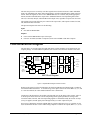
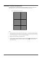
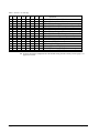
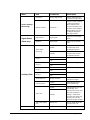
Cobalt Digital Inc. 9821 HD-Downconverter / DA with SD ARC User Manual 9821-UM Version: 1.0.3 9821 • Downconverter / DA with SD ARC User Manual • • • • • Cobalt Part Number: 9821-UM Document Version: 1.0.3 Printed in the United States. Last Author: SJK Printing Date: 10/26/07 10:13 AM The information contained in this User Manual is subject to change without notice or obligation. Copyright © 2007 Cobalt Digital Inc. All rights reserved. Contents of this publication may not be reproduced in any form without the written permission of Cobalt Digital Inc. Reproduction or reverse engineering of copyrighted software is prohibited. Notice The material in this manual is furnished for informational use only. It is subject to change without notice and should not be construed as a commitment by Cobalt Digital Inc. Cobalt Digital Inc. assumes no responsibility or liability for errors or inaccuracies that may appear in this manual. Trademarks Page 2 of 28 • is a registered trademark of Ross Video Limited. • • is a registered trademark of Cobalt Digital Inc. All other product names and any registered and unregistered trademarks mentioned in this manual are used for identification purposes only and remain the exclusive property of their respective owners. 9821 User Manual • (V 1.0.3) Important Regulatory and Safety Notices Before using this product and any associated equipment, refer to the “Important Safety Instructions” listed below so as to avoid personal injury and to prevent product damage. Products may require specific equipment, and /or installation procedures be carried out to satisfy certain regulatory compliance requirements. Notices have been included in this publication to call attention to these Specific requirements. Symbol Meanings This symbol on the equipment refers you to important operating and maintenance (servicing) instructions within the Product Manual Documentation. Failure to heed this information may present a major risk of damage or injury to persons or equipment. The symbol with the word “Warning” within the equipment manual indicates a potentially hazardous situation, which if not avoided, could result in death or serious injury. Warning The symbol with the word “Caution” within the equipment manual indicates a potentially hazardous situation, which if not avoided, may result in minor or moderate injury. It may also be used to alert against unsafe practices. Caution The symbol with the word “Notice” within the equipment manual indicates a situation, which if not avoided, may result in major or minor equipment damage or a situation which could place the equipment in a non-compliant operating state. Notice This symbol is used to alert the user that an electrical or electronic device or assembly is susceptible to damage from an ESD event. ESD Susceptibility Important Safety Instructions Caution This product is intended to be a component product of the openGearTM 8310 series frame. Refer to the openGearTM 8310 series frame User Manual for important safety instructions regarding the proper installation and safe operation of the frame as well as it’s component products. Warning Certain parts of this equipment namely the power supply area still present a safety hazard, with the power switch in the OFF position. To avoid electrical shock, disconnect all A/C power cords from the chassis' rear appliance connectors before servicing this area. Warning 9821 User Manual • (V 1.0.3) Service barriers within this product are intended to protect the operator and service personnel from hazardous voltages. For continued safety, replace all barriers after any servicing. This product contains safety critical parts, which if incorrectly replaced may present a risk of fire or electrical shock. Components contained within the product’s power supplies and power supply area, are not intended to be customer serviced and should be returned to the factory for repair. To reduce the risk of fire, replacement fuses must be the same type and rating. Only use attachments/accessories specified by the manufacturer. Page 3 of 28 EMC Notices US FCC Part 15 This equipment has been tested and found to comply with the limits for a Class A digital device, pursuant to part 15 of the FCC Rules. These limits are designed to provide reasonable protection against harmful interference when the equipment is operated in a commercial environment. This equipment generates, uses, and can radiate radio frequency energy and, if not installed and used in accordance with the instruction manual, may cause harmful interference to radio communications. Operation of this equipment in a residential area is likely to cause harmful interference in which case users will be required to correct the interference at their own expense. Environmental Information The equipment that you purchased required the extraction and use of natural resources for its production. It may contain hazardous substances that could impact health and the environment. To avoid the potential release of those substances into the environment and to diminish the need for the extraction of natural resources, Cobalt Digital Inc. encourages you to use the appropriate take-back systems. These systems will reuse or recycle most of the materials from your end-of-life equipment in an environmentally friendly and health conscious manner. The crossed-out wheeled bin symbol invites you to use these systems. If you need more information on the collection, reuse, and recycling systems, please contact your local or regional waste administration. You can also contact Cobalt Digital Inc. for more information on the environmental performances of our products. Page 4 of 28 9821 User Manual • (V 1.0.3) Contents Introduction 6 In This Chapter...........................................................................................................................6 A Word of Thanks......................................................................................................................6 Overview....................................................................................................................................6 Functional Block Diagram .........................................................................................................7 Available Format Conversions ...................................................................................................8 Documentation Terms ................................................................................................................9 Installation and Setup 10 In This Chapter.........................................................................................................................10 Static Discharge .......................................................................................................................10 Unpacking ................................................................................................................................10 Rear Module Installation (Optional) ........................................................................................11 Board Installation .....................................................................................................................12 Cable Connections....................................................................................................................12 Card Control and Status ...........................................................................................................13 Switch S1 ...................................................................................................................13 Switches 3 and 4 – Rotary Switch Settings ................................................................15 Switches 7, 8, 9 and 10 ..............................................................................................15 Status Reporting via LEDs.........................................................................................15 Remote Control 18 In This Chapter.........................................................................................................................18 DashBoard Control System Software.......................................................................................18 Specifications 23 Technical Specifications ..........................................................................................................23 Service Information 24 In This Chapter.........................................................................................................................24 Troubleshooting Checklist .......................................................................................................24 Software Upgrades ...................................................................................................................25 Warranty and Repair Policy .....................................................................................................25 Ordering Information 26 9821 and Related Products.......................................................................................................26 Contact Us 28 Contact Cobalt Digital Inc........................................................................................................28 Visit us at the Cobalt Digital Inc. website. ...............................................................................28 9821 User Manual • (V 1.0.3) Page 5 of 28 Introduction In This Chapter This chapter includes the following sections: • A Word of Thanks • Overview • Functional Block Diagram • Features • Documentation Terms A Word of Thanks Congratulations on choosing the openGearTM 9821 HD/SD Down Converter with SD ARC and Analog Outputs. The 9821 is part of a full line of modular conversion gear for broadcast TV environments. The Cobalt Digital Inc. openGearTM line includes video decoders and encoders, audio embeders and de-embeders, distribution amplifiers, format converters, and much more. Cobalt openGear modular conversion gear will meet your signal conversion needs now and in the future. Should you have questions pertaining to the installation or operation of your 9821, please contact us at the numbers listed on the back cover of this manual. We are happy to help with any questions regarding this or any other openGearTM card. Overview The 9821 is a high quality 10-bit, HD down-converter with SD pass-through and individual aspect ratio converter (ARC) controls for HD and SD inputs. The 9821 bridges SMPTE 292 high definition (HD) and 259M-C standard definition (SD) signal formats; allowing high density and low power conversion of HD signals. The 9821 will down-convert HD to SD serial component digital and analog composite video. This unit can re-aspect the image with separate rules for HD vs. SD inputs and adds 3:2 pull-down to 23.98 p/sF or i inputs. In addition, reticule overlays, for full aperture and safe area, in both 16x9 and 4x4 shapes can be enabled, as well as a center cross. Reticules can be separately enabled on the SD-SDI and composite outputs. The image processing is full 10-bit using a 24-tap spatial filter. Down-conversions of HD to SD signals are de-jittered to reduce chroma phase jitter of SD analog signals. The analog output is encoded at 12-bits (video plus sync) to preserve the 10-bit 4:2:2 component encoded video signal. Page 6 of 28 9821 User Manual • (V 1.0.3) The 9821 also preserves several key non video signals across a downconversion or ARC. Embedded audio is de-embedded at the input, delayed appropriately, and then embedded at the output in the new format. Timecode signals (as VITC or as in SMPTE RP-188) are extracted, delayed the appropriate amount, and then embedded in the output video. Standard definition closed captioning data (NTSC Line 21) is decoded, delayed, and embedded in the output video, regardless of aspect ratio correction. The product also provides full color proc control of the output video, with separate controls for Gain, Lift, Saturation and Color Phase. The input and outputs of the 9821 are the following: Input: One dual-rate HD/SD-SDI. Outputs: Four reclocked HD/SD-SDI copies of the input. Four user selectable (SD-SDI or Composite) down-converted HD or SD ARC’d outputs. Functional Block Diagram The 9821 has a very flexible signal flow path and feature set that combines several products into one compact package. To understand its capabilities, this section reviews the basic structure of the 9821. HD/SD Input Dual Rate Input Eq. Input Copies Re-clocked Outputs Down Conversion and ARC Dual Rate Reclock, Decode and De-serialize SD Encoder SD Analog Output Composite Routing SW and Reference Input Sel. SW Audio Memory Sync Detect Reticule Overlay Remote I/O or SD-SDI SD Serializer Frame Controller TCP-IP Analog Path SD Driver Output Microprocessor 9821 Block Diagram Figure 1. Simplified Block Diagram of 9821 Functions Starting in the upper left of the block diagram, the dual-rate (HD/SD) serial digital signal is equalized, reclocked and then deserialized. A reclocked copy of the input is driven out of four BNCs (3, 4, 5, and 6). Once deserialized, the video standard and frame rate is determined. Coming out of the deserializer, the parallel video data path goes to the image scalar circuitry, where it is down, aspect and/or frame rate converted depending on the signal input and user settings. After conversion audio, timecode, and closed captioning signals are embedded. Finally the reticule overlays (if any) are applied, and the signal passes through circuitry to reduce output clock jitter. Four copies of SD analog composite and SD-SDI are generated and sent to four, 2x1 switches (S7, S8, S9, S10) that allow the user to select either analog composite or SDI for the outputs (BNCs 7, 8, 9, 10). 9821 User Manual • (V 1.0.3) Page 7 of 28 Available Format Conversions The 9821 has extensive re-format and down conversion capabilities. It can act as a downconverter, ARC and frame rate converter. The format conversions are listed in the chart below. Table 1. Supported format conversions From 1080 1080 1080 1080 1080 1080 1080 1080 1080 1080 720 720 720 720 720 720 486 575 To sF 23.98 p 23.98 sF 24 p 24 i 25 p 25 i 29.97 p 29.97 i 30 p 30 p 25 p 29.97 p 30 p 50 p 59.94 p 60 i 29.97 i 25 SD 486 i 29.97 486 i 29.97 ---- none ---- none 575 i 25 575 i 25 486 i 29.97 486 i 29.97 ---- none ---- none 575 i 25 486 i 29.97 ---- none 575 i 25 486 i 29.97 ---- none 486 i 29.97 575 i 25 Notes: Page 8 of 28 1. All rates translated to effective frame rates, interlaced rates “ i ” are two times the number shown. For example, i 29.97 is 59.94 fields per second (two fields per frame thus the interlaced frame rate is 29.97); but progressive “ p ” 29.97 is 29.97 frames per second. 2. SD active line rates are PAL (575) and NTSC (486). 3. The 9821 cannot accept native 720 p23.98 or sF23.98, however it can convert those signals if they are delivered inside a p59.94 transportation wrapper (as typically done with this format) and processed as p59.94. 9821 User Manual • (V 1.0.3) Documentation Terms The following terms are used throughout this guide: 9821 User Manual • (V 1.0.3) • “Frame” refers to the 8310 frame that houses the 9821 card. • “Operator” and “User” both refer to the person who uses the 9821. • “Board” and “Card” all refer to the 9821 card itself, including all components and switches. • “System” and “Video system” refers to the mix of interconnected production and terminal equipment in which the 9821 operates. Page 9 of 28 Installation and Setup In This Chapter This chapter includes the following sections: • Static Discharge • Unpacking • Rear Module Installation (Optional) • Board Installation • BNC Labels • Cable Connections • LEDs and Buttons • Switch 3 and 4 – Rotary Switch Settings and LED reporting Static Discharge Whenever handling the card and other related equipment, please observe all static discharge precautions as described in the following note: Static discharge can cause serious damage to sensitive semiconductor devices. Avoid handling circuit boards in high static environments such as carpeted areas, and when wearing synthetic fiber clothing. Always exercise proper grounding precautions when working on circuit boards and related equipment. ESD Susceptibility Unpacking Unpack each card you received from the shipping container, and check the contents against the packing list to ensure that all items are included. If any items are missing or damaged, contact your sales representative or Cobalt Digital Inc. directly. Page 10 of 28 9821 User Manual • (V 1.0.3) Rear Module Installation (Optional) If you are installing the card in a 8310-C-BNC or 8310-BNC frame (one with a 100 BNC rear module installed across the entire back plane), skip this section. If you are installing the card into a slot with no rear module, you should have ordered and received a 8310-RM-A Rear Module with your card. You will need to install it in your 8310 frame before you can connect cables. Use the following steps to install the 8310-RM-A in an 8310 openGearTM frame: 1. Refer to the openGearTM 8310 frame User Manual, to ensure that the frame is properly installed according to instructions. 2. On the rear of the 8310, locate the card frame slot. 3. As shown in Figure 2, seat the bottom of the 8310-RM-A in the seating slot at the base of the frame’s back plane. Figure 2. Rear Module Installation 4. Align the top hole of the 8310-RM-A with the screw hole on the top edge of the 8310 back plane. 5. Using a Phillips driver and the supplied screw, fasten the 8310-RM-A panel to the 8310 back plane. Do not over tighten. This completes the procedure for installing the 8310-RM-A in an 8310 openGearTM frame. 9821 User Manual • (V 1.0.3) Page 11 of 28 Board Installation Use the following steps to install the card in the openGearTM 8310 frame: 1. Warning Refer to the User Manual of the openGearTM 8310 frame to ensure that the frame is properly installed according to instructions. Heat and power distribution requirements within a frame may dictate specific slot placement of cards. Cards with many heat-producing components should be arranged to avoid areas of excess heat build-up, particularly in frames using convection cooling. 2. After selecting the desired frame installation slot, hold the card card by the edges and carefully align the card edges with the slots in the frame. Then, fully insert the card into the frame until the rear connection plugs are properly seated on the midplane and rear modules. This completes the procedure for installing the card in the openGearTM 8310 frame. Cable Connections This section provides instructions for connecting cables to the installed BNC rear modules on the 8310 series frame backplane. Connect the input and output cables according to the following diagram. The input is internally terminated with 75 ohms. It is not necessary to terminate unused outputs. HD/SD-SDI Input 1 2 Not Connected Input Reclocked Copy 1 3 4 Input Reclocked Copy 2 Input Reclocked Copy 3 5 6 Input Reclocked Copy 4 SD-SDI / Analog Composite 1 7 8 SD-SDI / Analog Composite 2 SD-SDI / Analog Composite 3 9 10 SD-SDI / Analog Composite 4 Figure 3. BNC Designations for the Card Rear Module Page 12 of 28 9821 User Manual • (V 1.0.3) Card Control and Status The card can be configured and monitored in two ways: 1) Via DashBoard remote control software. Dashboard remote control software is the subject of chapter 3. 2) Via LEDs and switches on the front edge of the card Switch S1, located on the upper card edge, controls the primary functions of the card. ON is defined as the switch in the “UP” position, away from the board. OFF is defined as the switch in its “DOWN” position, towards the board. Switch S1 Switch S1 is located on the upper card edge and controls the primary functions of the card. ON is defined as the switch in the “UP” position, away from the board. OFF is defined as the switch in its “DOWN” position, towards the board. S1.1 -- Remote Control Enable S1.1 enables the remote control interface. If S1.1 is set to ON the user can control the 9821 card using Dashboard remote control software. Setting S1.1 to ON, disables switches S1.2 through S2.8. Control can be either from remote operators, or these card edge switches, but not both. If S1.1 is set to OFF, the remote control cannot set any card parameters, but can still monitor the status of the card. S1.2 through S1.5 – Aspect Ratio Control These switches will control aspect ratio for both HD and SD inputs separately. See Table 2 for the positions to select various preset or user defined aspect ratios. S1.6 – Underscan S1.6 will activate an “underscan” feature, further reducing a selected aspect ratio by 10 percent. S1.7 – Analog Composite Color S1.7 will enable or disable color on the SD analog output. S1.8 – Field Lock S1.8 will enable or disable the field locking feature on the card. Field lock is used to ensure that the output SD signals have the correct field polarity when 720p59.94 and 720p50 signals are used as the input. There is no information in the 720p signal that indicates which frames should be made into even fields and which should be made into odd fields. The Field Lock feature looks at the frame reference bus and makes sure that the output field polarity matches that of the reference bus. 9821 User Manual • (V 1.0.3) Page 13 of 28 Table 2. Switch 1 on card edge 1 2 3 4 5 ON OFF ON ON OFF OFF ON OFF ON OFF ON ON OFF OFF v Page 14 of 28 • ON OFF ON OFF 6 7 8 SETTINGS Remote Software Control Enable Remote Software Control Disable SD to SD User Settings (default: No aspect change) SD to SD 0.75 Vert Reduction (letter box) SD to SD 1.33 Horz Expansion (center cut) SD to SD No Aspect Change. HD to SD User settings (default: 1.33H center cut) HD to SD 0.75 Vert Reduction (letter box) HD to SD 1.33 Horz Expansion (center cut) HD to SD No Aspect Change ON Underscan ON (10% overall) OFF Underscan OFF (10% overall) ON SD Analog Color ON OFF SD Analog Color OFF (B&W) ON Enable Field Locking (for 720p downconvert) OFF Disable Field Locking (for 720p downconvert) If aspect ratio has been adjusted off of the default setting, then do a factory restore (page 17 or page 22) to correct. 9821 User Manual • (V 1.0.3) Switches 3 and 4 – Rotary Switch Settings The card has additional parameters which will need to be accessed less frequently. These are controlled via the rotary switches (S3 & S4) and the up/down thumb switch (S2) located on the card edge. The parameter number in question (00 through 99) is selected with the rotary switches. S3 selects the “10s” digit, and S4 selects the “1s” digit. For example, setting S3 equal to 3 and S4 equal to 1 selects parameter 31 (Y channel lift). The thumb switch S2 will increase or decrease the value of the parameter when pressed up or down. Some parameters have only a binary state. Press S2 up to turn them on, and down to turn them off. See Table 3 for a complete list of parameters settable through the rotary switches Switches 7, 8, 9 and 10 Switches S7, S8, S9 and S10 are used to select SD-SDI or SD analog output on the BNC corresponding to the switch number. If the switch is UP the output will be SD analog if the switch is DOWN the output will be SD-SDI. Status Reporting via LEDs When the switches S3 and S4 are set to “00” the card is in normal mode. In normal mode the “Lock Status” LED will blink when there is no signal present, turn solid orange for SD lock and solid green for HD lock. The “Input Standard” LED will be off if there is an SD signal present, orange if the input standard is 720 and green for an input standard of 1080. When adjusting the parameters, the three LEDs on the front card edge will report to the user the value of the setting. While viewing the card in its vertical position in the frame the top (POWER) LED will flash the number of 100s, the middle (LOCK STATUS) LED will flash the number of 10s, and the bottom (INPUT STANDARD) LED will flash the number of 1s. At the start of a numerical report all the LEDs will blink simultaneously. Example: the card is reporting a value of 275. The sequence is this: a blink of all LEDs->2 blinks of the 100s LED->7 blinks of the 10s LED->5 blinks of the 1s LED->repeat. For parameters that have only a binary state the “1s” LED (D14) will turn on for enabled and off for disabled. 9821 User Manual • (V 1.0.3) Page 15 of 28 Table 3. Parameters controlled through front edge switches S3S4 Parameter Description 00 01 02 08 09 10 11 12 13 14 15 16 17 18 19 30 31 32 33 34 35 36 40 41 42 43 44 45 46 47 Report Signal Lock Status Restore to 00 prior to device use Composite Output Composite output oversampling Composite output color bars Software Information Software release number Software build number Ancillary Data 24-bit audio processing Audio group 1 enable Audio group 2 enable Audio group 3 enable Audio group 4 enable Audio delay matches video delay (Up: enforce Down: allow different audio delay) Audio delay Audio delay is reported in hundredths of a second. Closed caption preservation enable Time code preservation enable Time code output line Proc Control Gain Lift Saturation Phase Background color hue Background color saturation Background color value Scalar H & V aspect zoom H aspect zoom V aspect zoom H aspect pan V aspect pan Prefilter type: 1) Better Frequency Response 2) Better Edge Response 3) Disable Prefilter Prefilter Aggressiveness: Up) attenuate more high frequency components Down) attenuate less HD to SD color matrix: Up) Enable Down) Disable Page 16 of 28 9821 User Manual • (V 1.0.3) 60 61 62 63 64 65 66 67 68 69 70 71 72 73 74 75 76 77 78 79 80 81 82 83 84 92 93 95 97 98 99 Reticules (Overlays) SDI reticule output enable Analog reticule output enable 4x3 full aperture (vert bars) 4x3 full aperture (vert bars) size 4x3 full aperture (vert bars) thickness 4x3 safe area enable 4x3 safe area horz size 4x3 safe area vert size 4x3 safe area horz thickness 4x3 safe area vert thickness 16x9 safe area enable 16x9 safe area horz size 16x9 safe area vert size 16x9 safe area horz thickness 16x9 safe area vert thickness Center cross enable Center cross horz size Center cross vert size Center cross horz thickness Center cross vert thickness Reticule(s) follow ARC Reticule Color: 1) White 2) Black 3) Blue 4) Red Reticule shadow Shadow luma Shadow chroma Miscellaneous Reference input select: Down) Reference 1 Up) Reference 2 Vbit correction Equalizer status error - if lit there is a bit error detected Save/Load Load factory defaults. Loading factory defaults will replace current saved settings Load saved settings Save current setting 9821 User Manual • (V 1.0.3) Page 17 of 28 Remote Control In This Chapter This section provides a detailed explanation on using remote control functions with your card. DashBoard Control System Software The DashBoard Control System enables you to monitor and control openGearTM frames and controller cards from a computer. The DashBoard software and manual can be downloaded from the Cobalt Digital Inc. website. Using the Menus You must first install the DashBoard Control System software on your computer. Refer to the DashBoard User Manual for software installation procedures and for using the DashBoard interface. The Menu System The following table and sections describe the menus, items, and parameters available from the DashBoard Control System software for the card. Table 3. DashBoard Menus Menu Card Info (Read-only) Software (Read-only) Page 18 of 28 Item Parameters Product CDI-9821 Manufacturer Cobalt Digital Inc. Description ##.## °C/##.## °F Current temperature of card at scalar IC. +12 Rail Current ### mA Supply Voltage Power #.# W Current power consumption of card Software Release Number # Temperature Software Build Number # 9821 User Manual • (V 1.0.3) Menu Switch Settings (Read-only) Signal Status (Read-only) Item Parameters S3 and S4 Rotary Edge Switch Reports which parameter is selected by edge switch Remote Software Switch S1-1 Reports if remote software is enabled or disabled. When enabled remote software can modify card parameters when disabled card parameters can only be changed through the card edge switches Input Format Input signal Reports the current input format. Equalizer Input signal Reports any detected bit errors Enable SD embedded audio will be 24 bits deep, with extended data packets. Disable SD embedded audio will be 20 bits deep, with no extended data packets. On Turn on/off audio group 1 24-bit Audio Processing Group 1 Group 2 Group 3 Ancillary Data Group 4 Audio Delay ms Closed Caption Off On Time Code Output Line 9821 User Manual • (V 1.0.3) Turn on/off audio group 2 Off On Turn on/off audio group 3 Off On Turn on/off audio group 4 Off Range 0-2700ms Enable Disable Enable Time Code Description Disable Range 6-22 Amount of audio delay from input to output Enable/Disable closed caption passthrough. Enable/Disable time code passthrough. Auto searches for first line with time code and passes it through. If more then one time code signal only the first time code line detected will pass through Selects which output line to embed VITC on Page 19 of 28 Menu Item Parameters Description No Aspect Change 0.75 V Letter Box 1.33 V 0.75 H Pillar Box HD to SD ARC 1.33H Center Cut User Setting User can save custom aspect ratio controls by using the save settings on the engineering tab No Aspect Change 0.75 V Letter Box 1.33 V 0.75 H Pillar Box SD to SD ARC Scalar Underscan 1.33H Center Cut User Setting User can save custom aspect ratio controls by using the save settings on the engineering tab Enable 10% H & V reduction Disable H Zoom Percent Range 20-1000% Horizontal zooming V Zoom Percent Range 20-1000% Vertical zooming H Pan Range 0-100 Horizontal panning V Pan Range 0-100 Vertical panning Better Frequency Response Filter Type Better Edge Response Disable Filter Filter Aggressiveness HD to SD color matrix Page 20 of 28 Range 0-20 Higher value filters more of the signal Enable Disable 9821 User Manual • (V 1.0.3) Menu Item SDI Parameters Enable Disable Enable Analog 4x3 Safe Area 4x3 Full Aperture 16x9 Safe Area Center Cross Disable Enable/Disable reticules on analog/composite output Disable Enable Disable Enable Disable Enable Disable Disable White Reticules (Overlays) Enable/Disable reticules on SDI output Enable Enable Reticules Follow Arc Description Reticules scale with video when scaled image when scaled image size is less then the active video size Color of the reticules Black Reticule Color Blue Red 4x3 Safe Area 4x3 Full Aperture Modify 16x9 Safe Area Center Cross Horizontal Size Range 0-100 Vertical Size Range 0-100 Horizontal Thickness Range 0-100 Vertical Thickness Range 0-100 Enable Disable Enable/Disable shadowing outside of the reticule boxes Shadow Luma Range 0-100 Percent of signal to pass Shadow Chroma Range 0-100 Percent of signal to pass Shadow 9821 User Manual • (V 1.0.3) Which reticule the following four items effect: Horizontal Size, Vertical Size, Horizontal Thickness, and Vertical Thickness Page 21 of 28 Menu Item Parameters Description Gain Range 0-200 As a percentage Lift Range 0-200 As a percentage Saturation Range 0-200 As a percentage Phase Range 0-360 In degrees Range 0-360 Adjusts background hue when scaled image size is less then the active video size Range 0-100 Adjusts background color when scaled image size is less then the active video size Range 0-255 Adjusts background value when scaled image size is less then the active video size Background Color Hue Proc Control Background Color Saturation Background Color Value On Oversampling Composite Output Off On Color Off On Color Bars Off Off Reference Reference 1 Turn on/off encoder oversampling of the composite output video Turn on/off color on the analog/composite output channels Turn on/off color bars on the analog/composite output channels Turn off reference or select which reference to use Reference 2 Reference Alignment Percent Miscellaneous SD Vbit Correction Enable Disable Reports the alignment percentage of the input video and reference input If enable V-bit will always be on line 20 Save Settings Save Save the current device configuration Load Settings Same as listed above Load the previously saved device configuration Same as listed above Load factory defaults. Note this will replace any saved settings with the factory defaults Load Factory Defaults Page 22 of 28 Input signal and reference signal 9821 User Manual • (V 1.0.3) Specifications Technical Specifications Table 4. Card - Technical Specifications Category Parameter Serial Digital Video Inputs Video Outputs Other Specification Number of Inputs 1 Data Rates Supported SMPTE 292 HD-SDI: 1.485 Gbps or 1.485/M Gbps SMPTE 259M-C SD-SDI: 270 Mbps Frame Rates Supported HD: 720p 25/29.97/50/59.94 1080i 25/29.97, 1080p 23.98/25/29.97 1080psF 23.98 SD: 486i 29.97 NTSC, 575i 25 PAL Impedance 75Ω terminating Equalization HD: 250ft (76 meters) Belden 1505A 200ft (61 meters) Gepco VDM-230 SD: 1000ft (300 meters) Belden 1505A Return Loss >15dB to 1.485GHz Number of Outputs 8 Outputs: 4: SDI Reclocked copies of the input signal 4: User configurable SD-SDI/Analog composite Impedance 75Ω Return Loss SD > 17 dB Signal Level 714mV ±10% DC Offset 0 Volts ±50 mV Total Power Consumption <8W Warranty Five Year Transferable Specifications are subject to change without notice. 9821 User Manual • (V 1.0.3) Page 23 of 28 Service Information In This Chapter This chapter includes the following sections: • Troubleshooting Checklist • Power LED Conditions • Software Upgrades • Warranty and Repair Policy Troubleshooting Checklist Routine maintenance to this openGearTM product is not required. In the event of problems with your card, the following basic troubleshooting checklist may help identify the source of the problem. If the module still does not appear to be working properly after checking all possible causes, please contact your openGearTM products distributor, or the Technical Support department at the numbers listed under the “Contact Us” section at the end of this manual. Page 24 of 28 1. Visual Review Performing a quick visual check may reveal many problems, such as connectors not properly seated or loose cables. Check the module, the frame, and any associated peripheral equipment for signs of trouble. 2. Power Check Check the power indicator LED on the distribution frame front panel for the presence of power. If the power LED is not illuminated, verify that the power cable is connected to a power source and that power is available at the power main. Confirm that the power supplies are fully seated in their slots. If the power LED is still not illuminated, replace the power supply with one that is verified to work. 3. Reseat the Card in the Frame Eject the card and reinsert it in the frame. 4. Check Control Settings Refer to the Installation and Operation sections of the manual and verify all user-adjustable component settings. 5. Input Signal Status Verify that source equipment is operating correctly and that a valid signal is being supplied. 6. Output Signal Path Verify that destination equipment is operating correctly and receiving a valid signal. 7. Module Exchange Exchanging a suspect module with a module that is known to be working correctly is an efficient method for localizing problems to individual modules. 9821 User Manual • (V 1.0.3) Power LED Conditions The top front edge of the module has a Power LED which indicates card status. The Power LED displays the following conditions: • Off no power to the card. • Amber the card is running internal diagnostics while powering up. • Green normal operation. Software Upgrades Software loads can be sent to the card using the MFC-8310-N Frame Controller with Networking. Software loads can also be sent to the card using a small eight pin ROM inserted in a dedicated upgrade socket. When the upgrade is complete, the ROM can be removed. Contact Cobalt Digital Inc. to acquire these upgrade ROMs. Warranty and Repair Policy The openGearTM card is warranted to be free of any defect with respect to performance, quality, reliability, and workmanship for a period of FIVE (5) years from the date of shipment from our factory. In the event that your Cobalt Digital Inc. card proves to be defective in any way during this warranty period, Cobalt Digital Inc. reserves the right to repair or replace this piece of equipment with a unit of equal or superior performance characteristics. Should you find that this openGearTM card has failed after your warranty period has expired, we will repair your defective product should suitable replacement components be available. You, the owner, will bear any labor and/or part costs incurred in the repair or refurbishment of said equipment beyond the FIVE (5) year warranty period. In no event shall Cobalt Digital Inc. be liable for direct, indirect, special, incidental, or consequential damages (including loss of profits) incurred by the use of this product. Implied warranties are expressly limited to the duration of this warranty. This openGearTM card User Manual provides all pertinent information for the safe installation and operation of your Cobalt Digital Inc. Product. Cobalt Digital Inc. policy dictates that all repairs to the openGearTM card are to be conducted only by an authorized Cobalt Digital Inc. factory representative. Therefore, any unauthorized attempt to repair this product, by anyone other than an authorized Cobalt Digital Inc. factory representative, will automatically void the warranty. Please contact Cobalt Digital Inc. Technical Support for more information. In Case of Problems Should any problem arise with your openGearTM card, please contact the Cobalt Digital Inc. Technical Support Department. A Return Material Authorization number (RMA) will be issued to you, as well as specific shipping instructions, should you wish our factory to repair your openGearTM card. If required, a temporary replacement module will be made available at a nominal charge. Any shipping costs incurred will be the responsibility of you, the customer. All products shipped to you from Cobalt Digital Inc. will be shipped collect. The Cobalt Digital Inc. Technical Support Department will continue to provide advice on any product manufactured by Cobalt Digital Inc., beyond the warranty period without charge, for the life of the equipment. 9821 User Manual • (V 1.0.3) Page 25 of 28 Ordering Information 9821 and Related Products Your 9821 HD/SD Down Converter with SD Pass Through and Analog Outputs is a part of the openGearTM family of products. Cobalt Digital Inc. offers a full line of openGearTM terminal equipment including distribution, conversion, monitoring, synchronizers, encoders, decoders, embedders, and deembedders, as well as analog audio and video products. Standard Equipment • 9821 HD/SD Down Converter • 9821-UM HD/SD Down Converter User Manual Optional Equipment Page 26 of 28 • 9821-UM HD/SD Down Converter User Manual (additional User Manual) • 8300-RM-A openGearTM Rear Module compatible with 9821 (10 BNC connector) • 8310-C Digital Products Frame and Power Supply with Cooling Fans (2RU, holds 10 cards) • 8310-C-BNC Digital Products Frame and Power Supply with fixed 100-BNC Rear Module and Cooling Fans. (2RU, holds 10 cards) • 8310-N-BNC Digital Products Frame and Power Supply with cooling fans, 100-BNC Rear Module, and MFC-8310-N card. (2RU, holds 10 cards) • MFC-8310-N Network Controller Card (Additional) 9821 User Manual • (V 1.0.3) Notes: 9821 User Manual • (V 1.0.3) Page 27 of 28 Contact Us Contact Cobalt Digital Inc. PHONE E-MAIL POSTAL SERVICE General Business Office and Technical Support 217.344.1243 Fax 217.344.1245 General Information [email protected] Sales Information [email protected] Cobalt Digital Inc. 2406 East University Avenue Urbana, IL 61802 USA Visit us at the Cobalt Digital Inc. website. http://www.cobaltdigital.com/ Page 28 of 28 • Online catalog • Related products and full product lines • Trade show information • Dealer information • Cobalt Digital Inc. news 9821 User Manual • (V 1.0.3)