1
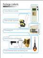
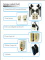
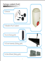
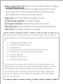
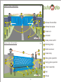
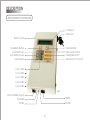
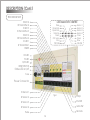
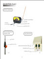
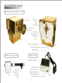
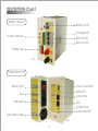
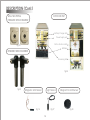
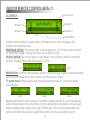
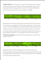
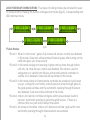
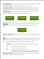
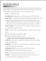
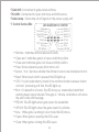
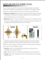
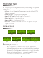
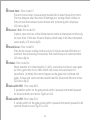
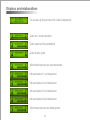
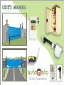
USER'S MANUAL
Gate Operators
Introduction
Welcome – We would like to take this opportunity to thank you for this
purchase. AUTOMATO has manufactured the finest automatic gate
operators available since 2005. Our commitment to quality and
innovation will become evident as you become familiar with the
features and performance of this expertly engineered machine.
Please take a few minutes to study the contents of this instruction
manual. The benefits of taking a little extra time to align the gate
operator properly and to verify a fully functional installation will ensure
customer satisfaction and a longer life with minimal maintenance
costs.
Installers and owners must be certain to thoroughly review and
understand the Important Information contained within this manual.
There are hazards associated with automatic gates that can be
greatly reduced with proper designing and installation. When an
automatic gate is first made functional, the installer must teach the
owners and users how to operate this system correctly. When the
installation is complete, leave this manual for the owner’s use and
reference.
Please do not hesitate to give your AUTOMATO distributor a call if you
experience any difficulties during the installation. They are
experienced and trained to assist in solving any problems.
2
Important Information
WARNING: To reduce the risk of serious injury, read and follow all
instructions in the gate operator handbook. Save These Important
Owner and User Instructions:
(Installers – be certain to instruct owners and users about the following
items)
m Never allow children to use or play with controls that operate gate. Keep
all remote controls, especially radio transmitters, away from children.
m Teach all users how to turn off electric power and how to release and
move gate manually. Use manual release only when gate is not moving.
m Test all functions, especially obstacle sensing mechanism of gate operator
monthly. Gate MUST reverse its direction of travel upon contact with a rigid
object and stop after moving a short distance. (Do not interrupt any of the
infrared sensors during this test). After 10 retrials the operator must halt. Also
test for normal functions of infrared sensors.
m KEEP AUTOMATIC GATES PROPERLY MAINTAINED. Have a professional gate
installer perform routine tests of entrapment protection sensors, such as
infrared sensors and obstacle sensing mechanism. Also, make all necessary
repairs to hardware to keep the gate running smoothly. Proper
adjustments should be made in the operator to decrease the risk of injury.
3
Limited Warranty
AUTOMATO Gate Operators warrants all of its manufactured products
to the end-user to be free of defects in material and workmanship. All
operators are warranted for a period of one year from date of
shipment.
Slide gate operator drive wheels are warranted for a period of one
year and batteries are warranted for one year from the date of
shipment. Any modification made to factory products will void the
warranty unless modifications are approved in writing by factory, in
advance of the change. This exclusion does not apply to normal
installation of approved accessories and/or safety devices. This
warranty will not be applied to equipment which has been improperly
installed, subjected to negligence, accident, damage by
circumstances beyond AUTOMATO Gate Operators' control, or
because of improper operation, maintenance, storage or to other
than normal use or service.
Labor to install new parts or remove defective parts, travel time, or
standby time is specifically excluded from this warranty. Freight and all
other incidental costs are NOT covered by this warranty. Defective
products that are in warranty should be returned to our factory. At our
option, we may choose to repair or replace, free of charge, any such
parts.
4
Package contents
1.Indoor Remote Controller
2.Remote Radio Transmitters
3.Processing Unit
4.Motor And Gate Lock Assembly
swing gate
slide gate
5.Radio Receiver Module and Warning Lamp
5
Package contents (Cont.)
6.Infrared Receiver & Transmitter Modules
7.Gate Switches
8.Intercom/Calling Bell Switching Unit
9.Power Supply Unit
10.Battery Charger Unit
11.Batteries
6
Package contents (Cont.)
12.Sensors
13.Weather Proof Cabinet
14.Lock (Swing gate)
15.Chain Assembly (Sliding gate)
16.Gate Wheels (Sliding gate)
7
Features
AUTOMATO slide gate and swing gate operators are unique in the industry,
has many features that make it front runner in its class.
¤ Indoor remote controller: With this wired remote control installed inside your
house you can monitor and control gate even from the distance of
200metres. Position and movement of gate, status of infrared sensors, error
messages etc. are shown on back lighted LCD. Two soft touch buttons are
for provided for partial and full opening of gate. Switches for gate lamp,
calling bell and intercom/cctv are also provided.
¤ Coded radio remote controller: With which you can open and close gate
from your vehicle. The range of remote is about 100 metres, and is
powered from vehicle battery or with 23AE/12v alkaline battery.
¤ Instant Reversal using IR sensors: Interruption of any infrared sensor beams
while gate is closing reopens the gate.
¤ Obstacle sensing mechanism: AUTOMATO gate operator has a built in
safety feature which when adjusted properly will deliver only enough power
to motor to overcome the resistance of gate. Amount of force necessary to
stop the gate can be adjusted to conform to the various sizes and weights
of any particular gate. Separate adjustments for both the opening and
closing direction are provided. Upon sensing an obstacle on path, gate
moves backwards and retries ten times to close/open, then halt. These
retrials may help to clear the obstacle away.
¤ Auto Close timer: Operator is factory preset with auto close timer function
which will close the gate automatically after a specific amount of time has
elapsed. For pedestrian use amount of time is 4 seconds, and for
8
vehicular use it is 60 seconds. Interrupting any of the infrared sensors restarts
auto close timer. When the gate is opened for vehicle, passing of vehicle
through gate interrupts all infrared sensors which then resets auto close
timer to 4 seconds.
¤ Soft start/stop in open and close travel motions: Unique feature of
AUTOMATO is the Soft Start/Soft Stop feature. Traditional gate operators
may begin opening the gate with full power causing a yanking or jerking
effect. AUTOMATO will begin opening/ closing gate very slowly and will
gradually increase to full speed. Then gradually decreases speed before
stopping. This creates a very gentle gate translation which considerably
reduces the amount of wear and tear on all mechanical parts.
¤ Auto-open feature: Infrared sensors 3 and 4 are provided for automatic
opening of the gate. When beam of infrared sensor-3 is interrupted, gate
will open 1/3 of its travel for pedestrian. If sensor3 and 4 are interrupted
together then gate opens fully for vehicles.
¤ Automatic calling bell: When some one comes in front of the gate and
interrupts infrared sensor-1 the calling bell will ring. Pressing gate panel
switches or open button on radio remote also rings the calling bell. When
operator is in locked mode and user tries to open with remote or panel
switch, it will not open but sounds the calling bell. If the user tries to open
the gate again without knowing that it is locked will cause repetitive rings.
This annoyance is eliminated by implementing a delay of 10 seconds
between consecutive rings.
¤Automatic camera and intercom: When user comes in front of gate and
interrupts infrared sensor-1 or presses any gate panel switch, or open button
9
on radio remote, that will switch on power to a CCTV/intercom. Meantime
gate lamp also is switched on to light up the area for CCTV camera, and
illumination LEDs on gate panel switch starts to blink. After 30 seconds, the
power to gate lamp, intercom /CCTV and illumination LEDs are switched
off if gate is in closed position. Otherwise stays on.
¤ Intruder alarm : When in locked mode(1,2&3), if someone tries to tamper
gate lock and open gate by force the intruder alarm function is activated.
¤Error display on the indoor unit: This LCD helps to simplify installation and
troubleshooting for installer and user.
¤Five modes of locks with child lock: When in lock mode-1, it is fully locked
and all access controls are disabled. Removing the key after turning on
child lock gives you more security. In lock mode-2 closing and opening of
gate can be done through indoor unit only. This mode is useful to
safeguard your vehicle from thieves as the radio remote controller on the
vehicle is disabled. In lock mode-3, indoor unit and remote controller are
enabled. Useful when you go outing with your family, nobody else can
enter through gate as the gate panel switches and the automatic opening
through IR sensors are disabled. In lock mode-4, the Indoor unit, remote
controller and gate switch are enabled but the automatic opening
through infrared sensors is disabled. Useful to prevent automatic opening of
gate if there is a chance that your pets may interrupt the beam. In lock
mode-5 All access controls like Indoor unit, remote controller, gate switch
and automatic opening through infrared sensors are enabled.
¤Vehicle and pedestrian mode: Partial opening of gate for pedestrians use
and full opening of gate for vehicle are implemented.
10
¤Manual closing function : Incase, the gate is not closed and showing some
error message on indoor unit, and if you cannot attend at that time,
manual closing of gate can be done from indoor remote controller, except
on error message obstacle on track.
¤Warning lamp : Warning Lamp will flash when the gate is closing or opening.
¤Twilight switch for gate lamp: Twilight switch is provided to switch on gate
lamp at dusk and switch off at dawn automatically.
¤Maximum Run Timer of five minutes for motor in both directions.
¤LED diagnostic center :Implemented for easy on-site trouble shooting. These
LEDs help to simplify installation and troubleshooting for installer and user. A
switch is provided to turn off diagnostic centre on normal operation for
power saving.
¤Reversible gate direction(sliding gate) : For right or left handed operation.
¤Manual release lever: Upon complete system failure (lightning, surges, etc...)
gate can be pushed open/close by hand. This simple push-pull lever is built
into front side of the operatorof sliding gate. By pulling and turning this
lever gate can be released from driving mechanism. For swing gate keys
are provided to unlock the motor and lock.
¤Manual lock release: Upon complete system failure gate can be unlocked
by pushing this lever manually.
¤Built in battery backup: Inherent 24 VDC backup power with two 12V-7Ah
batteries. The having battery back-up is the ability to open and close gate
even when there is no power. On power failure gate can be operated up
to 150 times before power is restored.
¤Microcomputer based electronics with watch dog reset timer.
¤MOSFET motor drive: State of the art MOSFET motor drive technology
11
¤Battery charger with cut-off: When the level of charge reaches full, charging
of battery is stopped. When the level of charge reaches below low level,
power supply output to all the units are switched off to prevent battery
drain. When power is restored output is also restored.
¤High torque 1/6 HP 24 volt Permanent Magnet DC motor .
¤Continuous duty operation for most types of gates.
¤All rust proof construction with baked on powder coat enamel.
¤Direct drive gear reducer eliminates many parts that might otherwise fail.
¤Safe 24 VDC low voltage motor and control wiring.
Some special functions are also implemented in AUTOMATO operator. User or installer can
enable/disable some functions by using the reset key on special way at startup. The functions
are:³ 1. Gate lamp blinks when gate is moving.
³ 2. Warning lamp when gate is moving.
³ 3. Calling bell delay.
³ 4. Auto reversal function on interruption of IR sensor-3 and IR sensor-4.
³ 5. latch the lock on mode 1,2 &3 or latch on all lock modes
³ 6. Automatic calling bell
³ 7. Pedestrian opening 1/3 or 1/2
³ 8. Slide gate/ Swing gate mode
To do this power of the operator, press and hold on the reset switch and power up the
operator. After 10 seconds some beeps are produced showing that system is now ready for
input through reset switch. Then four small beep sounds are produced at intervals of 3
seconds between beeps. If the reset key is pressed during these beeps, corresponding
function is set to disable, else set to enable. After some beeps operator then restarts to
normal functioning mode.
12
Swing Gate Schematic
fig.1
7
6
8
2
1
1 Infrared transmitter
2 Infrared receiver
10
3
4
3 Gate lock
4 actuator
5
5 Gate panel switch
Slide Gate Schematic
fig.2
7 Radio receiver
7
8
8 Gate lamp
6
2
5
1
3
13
12
11
13
9
6 Warning lamp
9 Slide gate operator
10
Swing gate operator
11
Chain assembly
12
Rail
13
Wheel
DESCRIPTION
INDOOR REMOTE CONTROLLER
LC Display
Child Lock
Buzzer on/off
Vehicle Button
Gate Lamp on/off
Calling Bell on/off
Intercom/CCTV on/off
Pedestrian Button
Lock Button Up
Lock Button Down
reset button
Lock 1 LED
Lock 2 LED
Lock 3 LED
Lock 4 LED
Lock 5 LED
fig.3
Intercom&Bell Output
RS485
R/W LED
TX LED
RX LED
14
DESCRIPTION (Cont.)
PROCESSOR UNIT
IR LED 4
IR Transmitter 4
IR LED 3
IR Tramsmitter 3
IR LED 2
IIR Transmitter 2
IR LED 1
IR Transmitter 1
RS485
LED DIAGNOSTIC CENTRE
Pulse
Close End
Open End
Remote
Reset
CRC error
Error
PED SW
Sensor 1
Sensor 2
Sensor 3
Sensor 4
Close
Open
Slow
VEH SW
RX LED
TX LED
R/W LED
RESET SWITCH
Status LED on/off
Fuse
Power Connector
IR Sensor 1
fig.4
IR Sensor 2
Lamp
IR Sensor 3
End SW
IR Sensor 4
Gate SW
Remote
Pulse
15
DESCRIPTION (Cont.)
REMOTE CONTROLLER
Antenna (Adjustable)
TX LED
+12v from
car battery
Open switch
fig5
Close switch
REMOTE FM RECEIVER &
WARNING LAMP
GATE PANEL SWITCH
Antenna
Warning Lamp
Gate switch illumination LEDs
Pedestrian switch
Vehicle switch
fig.6
fig.7
16
DESCRIPTION (Cont.)
SLIDE GATE MOTOR AND LOCK UNIT
Lock
fig.8
Manual
Lock
Release
Chain Driving
Sprocket
Manual
Emergency
Release
Lever
Power Connector
Pulse Output
Pulse LED
SWING GATE ACTUATOR
fig.8a
INTERCOM UNIT
Calling Bell Output
fig.9
Manual
Emergency
Release
Key
Intercom/
CCTV output
Calling Bell LED
Intercom LED
Connector
17
fig.10
DESCRIPTION (Cont.)
BATTERY CHARGER
Battery on/off
Charging LED
Power Connector
Batt. Full LED
Batt. Low LED
Battery Fuse
fig.11
POWER SUPPLY UNIT
Power Connector
Mains on/off
Mains LED
Gate Lamp
Fuse
Mains Inlet
LDR
Twilight Level
Gate Lamp LED
Gate Lamp Outlet
fig.12
18
DESCRIPTION (Cont.)
OUTDOOR UNIT
WALL MOUNTING
INFRARED SENSOR BARRIER
Battery Charger Unit
Power Supply unit
Motor And Lock Unit
fig.13
Batteries
INFRARED SENSOR BARRIER
Processing Unit
fig.14
fig.15
Magnetic Limit Sensor
Light Sensor
fig.16
fig.17
19
Magnet For Limit Sensor
fig.18
INDOOR REMOTE CONTROLLER(fig.1)
LC DISPLAY :
Gate Lamp
IR Sensor 3
IR Sensor 1
IR Sensor 4
IR Sensor 2
fig.19
Gate Position
Position and movement of gate, status of infrared sensors, error messages, and
functions are displayed here.
PEDESTRIAN BUTTON : This button helps to open gate to its 1/3 of travel, which is meant
for pedestrian usage. Pressing this button shows fig.20 on LCD.
VEHICLE BUTTON: This button helps to open gate to full of its travel, which is meant for
vehicles. Pressing this button shows fig.21 on LCD.
fig.20
fig.21
RESET BUTTON : Functions like resetting system, manual closing of gate, travel limit setting
are selected through this button. Inherent functions are as follows.
v System Reset: When reset button is pressed approximately for 2 seconds, display
shows fig.22a .
fig.22a
fig.22b
fig.22c
Releasing the button starts resetting of operator. Displays fig.22b. If any of the infrared
sensor is interrupted or any obstacle is on track, gate opens and display shows fig.22c.
After resetting system, display shows fig.19. Back light of the LCD and gate lamp are
switched off after 30 seconds. If gate lamp button is on then gate lamp stays lit.
20
v Manual Closing : Incase, the gate is not closed and is showing some error message
on indoor unit, and you cannot attend at that time, manual closing of gate can be
done (except the error message obstacle on path). To do this press and hold down
reset button approximately for 4 seconds, the display shows fig.23a.
fig.23a
fig.23b
fig.23c
fig.23d
Releasing button starts manual closing. Display shows fig.23b. After the gate is closed,
indoor unit shows message fig23c. If manual closing is stopped due to some obstacle
on path, LCD shows message fig.23d. Operator stays either of these condition and all
functions except reset, manual closing and limit setting are disabled. To exit from this
mode reset the system through reset button on indoor panel (see system reset p14) or
press pedestrian/vehicle button, or by pressing the reset switch on processing unit.
vGate Travel Limit Setting : Press and hold down approximately for 6 seconds shows
fig.24a on indoor unit.
fig.24a
fig.24b
fig.24c
fig.24d
Releasing this button starts limit resetting function. During this time gate closes
(LCD shows fig.24b) and sets close end limit (if gate is at close end limit this function will
be skipped) and then opens fully and sets open end limit (fig.24c). Then closes (fig.24d).
Do not interrupt the function till it ends.
21
LOCK POSITION UP/DOWN BUTTONS : Five types of locking modes are provided for users
to access control. Pressing this buttons changes lock modes (fig.25). Corresponding lock
LED indicates mode.
fig.25
vLock Modes:
²Lock1: When in lock mode 1 gate is fully locked. All access controls are disabled
²Lock2:
²Lock3:
²Lock4:
²Lock5:
in this mode. Gate lock will be latched. Removing key after turning on the
child lock gives you more security.
In this mode closing and opening of gate can be done through indoor
unit only. All other access controls are disabled. This mode is useful to
safeguard your vehicle from thieves as the radio remote controller on
vehicle too is disabled. Gate lock will be latched in this mode.
In this mode indoor unit and remote controller are enabled. Useful when
you go outing with your family, nobody else can enter through gate as
the gate panel switches and the automatic opening through IR sensors
are disabled. Gate lock will be latched in this mode.
Indoor unit, remote controller and gate switch are enabled. Useful to
prevent automatic opening of gate through IR sensors, if there is a
chance that your pets may interrupt the beam.
All access controls like Indoor unit, Remote controller, gate switch and
automatic opening through infrared sensors are enabled.
22
GATE LAMP BUTTON: Gate lamp button is used to switch on/off the gate lamp. Blue LED
is provided as indicator. Pressing this buttons shows fig.26 on LCD
CALLING BELL BUTTON: To enable or disable calling bell use this button. Yellow LED
indicates whether the calling bell is enabled or not. Pressing this buttons shows fig.27.
INTERCOM BUTTON: To enable or disable CCTV/intercom use this button. Green LED
shows the condition. Pressing this buttons shows fig.28 on LCD
fig.26
fig.27
fig.28
CHILD LOCK: Child lock to on position disables the lock changing buttons and denies
access for kids. when child lock is on, pressing lock buttons shows fig.29 on indoor
display.
fig.29
INTERCOM / BELL OUTPUT: This socket provides output to intercom/calling bell switching
unit
RS485: This port is connected to processing unit through which data and power lines are
linked. If any of these lines are disrupted processing unit starts resetting the operator
after a long warning beep, meantime indoor unit also produces a beep.
s R/W LED: Shows whether transmission or reception of data is taking place.
s TX:
This red LED tells transmission of data.
s RX:
This green LED shows reception of data.
*** All these LEDs will flicker during proper data communication.
BUZZER ON/OFF SWITCH: This switch is helpful to turn off warning beep sound produced
when power supply to the indoor unit is disrupted.
23
PROCESSING UNIT(fig.4)
This unit receives, sends, processes data and controls the connected units. Indoor unit,
Battery Charger, Power supply, Remote radio receiver, gate switches, end limit sensors,
infra red sensors, warning lamp, motor units etc are associated units.
²fuse: Fuse for gate lock (10A)
²Stat LEDs on/off : Diagnostic centre LEDs can be set to on/off by this switch.
²Reset switch : Functions like system reset and limits can be selected by this switch.
Pressing and releasing this switch within 2 seconds cause the system to start
resetting. Pressing and holding down for at least 5 seconds turns the system into
limit setting mode. In this mode system marks open end and close end limits.
²Power connector : Connections to motor box, battery, charger, warning lamp
etc. are done through this connector.
²R/W : This yellow led shows whether transmission or reception of data is taking
place.
²TX: This red LED indicates transmission of data.
²RX: This green LED shows reception of data.
*** All these LEDs will flicker during proper data communication.
²IR LED 1 to 4: If connection between the corresponding infrared transmitter is
ready, green LED flickers.
²RS485 port : Port to indoor unit or PC. If no device is connected, the operator
resets and warning beep is produced.
²IR Transmitter 1 to 4: Connected to infrared transmitter modules.
²IR Sensor 1 to 4 : Connected to infrared receiver modules.
²Pulse: Connected to pulse sensing module in the motor box unit.
²Remote : Connected to radio receiver module. If this is not connected, the
operator will reset and a warning beep is produced.
24
²Gate SW :Connected to gate panel switches.
²End SW : Connected to open and close end limit sensors.
²Gate Lamp : Gate lamp on/off signals to the power supply unit.
² Control Centre LEDs :
LED DIAGNOSTIC CENTRE
Pulse
Close End
Open End
Remote
Reset
CRC error
Error
PED SW
Ÿ
Ÿ
Ÿ
Ÿ
Ÿ
Ÿ
Ÿ
Ÿ
Ÿ
Ÿ
Ÿ
Ÿ
Ÿ
Sensor 1
Sensor 2
Sensor 3
Sensor 4
Close
Open
Slow
VEH SW
Remote : Indicates remote receiver is ready.
Open end : Indicates gate is at open end limit position.
Close end: Indicates gate is at close end limit position.
Pulse: Shows reference pulse from motor unit.
Sensor 1 to 4 : Denotes whether the infrared sensors are interrupted or not.
Reset: When reset switch is pressed this LED lights up.
CRC: If cyclic redundancy check in the communication between indoor
unit and processing unit fails, this LED lights up.
Error: On detection of errors, this LED shows up. Meanwhile intermittent
warning beeps are produced. Time gap is 1 minute. And indoor units show
the error code with message.
PED SW: This LED lights when gate opens for pedestrian.
VEH SW: This LED lights when the gate opens for vehicles.
Slow : While gate is working in slow mode this LED shows.
Open: When gate is opening this LED is seen.
Close: When gate is closing this LED is seen.
25
MOTOR AND GATE LOCK ASSEMBLY (fig.5&6)
PU
LL
A
N
Swing gate
fig.31
PU
LL
A
D
D
A
R
TU
R
TU
R
TU
PU
LL
N
D
AUTOMATIC
Slide gate
AUTOMATIC
N
PU
LL
R
TU
N
N
D
N
A
This unit contains a geared DC motor, gate chain driving sprocket, load releasing
mechanism for emergency opening/closure, electrical lock with emergency release
mechanism, obstacle sensing mechanism and a reference pulse sensing module.
² Emergency Lock Release: When the system has got locked and stopped functioning
( may be due to power failure for long time which will turn into low battery cutoff),
then by pulling this lever lock can be released.
² Manual Lever: When the system has stopped functioning, then by pulling and turning
this lever to 90 degrees releases gate from the driving mechanism for slide gates. For
swing gate keys are provided to unlock the motor and lock.
MANUAL
D
N
PU
LL
A
N
D
R
TU
N
D
AUTOMATIC
N
N
R
TU
R
TU
AUTOMATIC
D
fig.30b
A
A
fig.30a
PU
LL
PU
LL
R
TU
N
MANUAL
N
N
MANUAL
N
N
MANUAL
Lock lever
Actuator key
Lock lever
PU
LL
A
Fig.30a shows gate is released from the driving mechanism. Switch off the mains
on/off switch and battery on/off switch before turning this lever to manual position.
Fig.30b shows gate is engaged to driving mechanism. Only After turning to this position,
you must turn on mains and battery switches.
² Connector : Motor, lock, obstacle sensing mechanism are connected to the
processing unit through this connector.
² Pulse : Through this connector reference pulse signals are sent to processing unit.
² Pulse LED: When power is supplied to the motor, this led indicate that pulse sensing
module is active.
26
POWER SUPPLY UNIT (fig.10)
This unit is containing a power transformer to supply power to the whole system, main
switch, mains fuse, and twilight switch for gate lamp. Twilight switch switches on gate
lamp at dusk and switches off at dawn automatically.
²Mains on/off: To turn on/off mains. Neon bulb inside switch indicates mains.
²Fuse : Fuse for mains.
²Mains Inlet : Mains input socket.
²Gate lamp outlet : Gate lamp outlet socket.
²Power connector : Connected to battery charger unit.
²Mains LED : This LED shows presence of mains.
²Gate lamp : Gate lamp on/off signal from processing unit.
²LDR: Light sensor of twilight switch is connected to this socket. Set this sensor such
that, it only catches the daylight.
²Twilight Level: Light level adjusting screw, where at the lamp must switch on/off.
²Gate lamp LED: Lights when gate lamp is on.
BATTERY CHARGER UNIT (fig.9)
This is the battery charger & controlling unit. Full charge level is set to 27.2 volts. When
the level of charge reaches above this level, charging stops and battery full LED lights
up. Battery low level is set to 16 volts. When the level of charge reaches below this
level, low battery LED lights up and power supply output to the operator is switched off
to prevent battery drain.
² Power connector : Connected to power supply unit , battery and processing unit.
² Charging LED: Battery charging indicator.
² Batt. full LED : Battery full indicator.
² Batt. low LED : Battery low indicator. Shows battery low indicator for 2 seconds,
then cuts off the output to prevent battery drain.
27
INTERCOM UNIT (fig.8)
This unit supplies power to calling bell and intercom/cctv according to the signal from
processing unit.
² AC cord : Connect this wire to AC outlet socket where calling bell and CCTV&
intercom are installed.
² Calling bell output : AC outlet socket for calling bell.
²Intercom/CCTV output : AC outlet socket for intercom/cctv.
²Calling bell LED: Lights when calling bell is on.
²Intercom LED: Lights when intercom/cctv is on.
²Connector: This socket is connected to indoor unit through which the on/off
signals are received.
ERROR MESSAGES
fig.31
fig.34
fig.32
fig.35
fig.33
fig.36
fig.37
ýObstacle on path : Error code 010
When the gate comes in contact with some obstacle on its path, and
obstacle sensing mechanism detects that, gate travels little backwards and
tries again. After 10 retrials operator halts the motor and stays in this condition
till a user reset. Indoor unit shows error message obstacle fig.31. Warning
beeps are produced from processing and indoor units.
28
ýCheck track :
Error code 011
This error occurs when pulse sensing module fails to detect pulse from motor.
This may happen when the motor is damaged or sensing circuit is failed, or
if the connection between pulse module and processing unit is improper.
LCD shows fig.32.
ýIR sensor 1 to 4:
Error code 012
If gate is open and any of the infrared sensor barrier is interrupted continuously
for more than 15 minutes, this error displays which helps to find the interrupted
sensor easily. LCD shows fig.33.
ýNeutral lever :
Error code013
If the motor is been working continuously for 5 minutes and end limit has not
reached, then processing unit assumes that neutral lever is in neutral position.
LCD shows fig.34.
ýIntruder:
Error code 014
When operator is in locked position (1,2& 3), and some one tries to open gate
by force, gate may move a little which may cause close end sensor to
deactivate. ( normally this cannot happen as the gate lock is latched with
gate). If close end sensor remains deactivated for 45 seconds this error shows.
LCD shows fig.35.
ýGate switch PED:
Error code 0015
If pedestrian switch on the gate panel switch is pressed and remain pressed
for 40 seconds this error shows. Fig.36 on LCD.
ýGate switch VEH:
Error code 0016
If vehicle switch on the gate panel switch is pressed and remain pressed for 40
seconds this error shows. Fig.37 on LCD.
29
Displays and elaborations
On power up the product id code is displayed.
Gate is in closed position
Gate opened for pedestrian
Gate is fully open
All infrared sensors are uninterrupted.
Infrared sensor 1 is interrupted
Infrared sensor 2 is interrupted
Infrared sensor 3 is interrupted
Infrared sensor 4 is interrupted
All infrared sensors are interrupted.
30
Notes
Dear customer,
Please visit our website http://www.automato.in and register your name to post complaints and suggestions online.
Key code :
Customer code :
31
www.automato.in