1
VEGA 76
11.
MEASURING PROCEDURES
11.1. USING THE INSTRUMENT IN A SINGLE PHASE SYSTEM
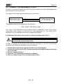
CAUTION
The maximum voltage between B1 and B4 inputs is 600 V~ (CATII) / 350V~
phase – earth or 600V~ (CATIII) / 300 V~ phase to earth. Do not measure
voltages exceeding the limits prescribed by this manual
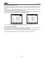
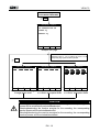
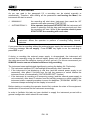
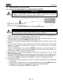
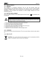
Instrument connection in a single-phase system
CAUTION
If possible, before connecting the instrument to the electrical equipment to
be tested take the power supply off the electrical equipment.
1. Check, and if needed modify, the basic settings of the instrument (see paragraphs 5.2
and 5.3). Particularly, the single-phase mode must be set.
2. Rotate the switch to the position corresponding to the type of analysis desired. In case
of doubts select the position POWER (see paragraph 6.3).
3. Connect the phase and neutral voltage wires respecting the connections shown in the
picture.
4. If you want to measure current and power, connect the clamp meter to the phase
conductor respecting the specifications shown on the clamp and the connections
shown in the picture.
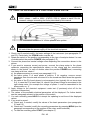
In case of doubts select the position POWER and check if the active power P is
positive. If it’s negative, remove current transducer from the wire and reconnect it so
the transducer label faces the opposite direction.
5. Apply voltage to the electrical equipment under test (if previously shut off for the
instrument connection).
6. The values of the available electrical parameters will be displayed on the display of the
instrument. For further details see the paragraph relevant to the position of the switch.
7. You can press HOLD to interrupt the updating in real time of the displayed values.
8. If you want to record:
a) Check, and if needed modify, the values of the basic parameters (see paragraphs
5.2 and 5.3).
b) Check, and if needed modify, the recording parameters by pressing MENU (see the
paragraph corresponding to the position of the rotary switch selected).
c) To start the recording press START (see chapter 6).
EN - 41




![TSD Series -40C ULT User Manual [EN]](http://vs1.manualzilla.com/store/data/005634658_1-66c9db561a67486106446026c707a26c-150x150.png)