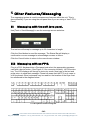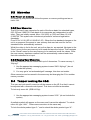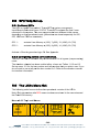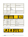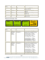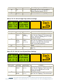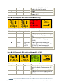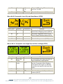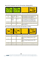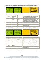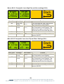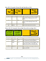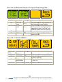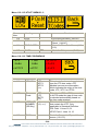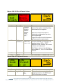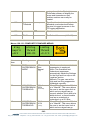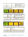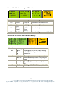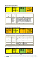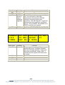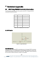
1
eyeheight
LE-2n
Multimode SDHDI Legaliser in a desktop chassis with software
control application.
user manual
User Manual Versions
Versions
Changes
Date
Build
1.0
First Version for LE-2 in nanobox chassis
5/6/2009
V113
1.1
Improved Driver installation clarity
05/08/09
V113
LE-2 Product History
-2eyeheight Unit 34 Park House Watford Business Park Greenhill Crescent Watford Herts GB WD18 8PH
Reg. No. 2855535 Telephone: +44 (0) 1923 256 000 Fax: +44 (0) 1923 256 100 email: [email protected]
Table of Contents
1. System Overview .......................................................................................... 6 1.1 The nanobox chassis .............................................................................. 6 1.2 The LE-2n Product .................................................................................. 7 2 Setting up the LE-2n.......................................................................................... 9 2.1 Associated equipment. ............................................................................ 9 2.2 Connecting the LE-2n using a soft panel. ............................................... 9 2.2.1 Installing the software. ....................................................................... 10 2.2.2 System Requirements........................................................................ 10 2.2.3 Java ................................................................................................... 11 2.2.4 RxTx Serial Drivers ............................................................................ 11 2.2.5 Granting a user permission to open a COM Port in Mac OS X .......... 11 2.2.6 USB to Serial Drivers ......................................................................... 12 2.3 Screen Layout ....................................................................................... 13 2.3.1 Toolbar............................................................................................... 13 2.3.2 Device Info. ........................................................................................ 14 2.3.3 Status Bar .......................................................................................... 15 2.3.4 Display Buttons .................................................................................. 15 2.3.5 Rotary Controls .................................................................................. 15 2.3.6 Next & Previous Buttons .................................................................... 16 2.4 Menu Navigation ................................................................................... 16 2.4.1 Go To Another Menu ......................................................................... 16 2.4.2 Single Parameter Adjustment ............................................................ 16 2.4.3 Double Or Triple Parameter Adjustment ............................................ 17 2.4.4 Information Display ............................................................................ 17 2.5 Connecting the LE-2n using an FP-9. ................................................... 17 2.5.1 Flexipanel controls. ............................................................................ 18 2.5.2 Device Buttons. .................................................................................. 18 2.5.3 Menu Navigation. ............................................................................... 18 2.5.4 Parameter adjustment of a green menu............................................. 18 2.5.5 Parameter adjustment of a red menu................................................. 19 2.5.6 Information display ............................................................................. 19 3 Connecting Video to the LE-2n ........................................................................ 20 -3eyeheight Unit 34 Park House Watford Business Park Greenhill Crescent Watford Herts GB WD18 8PH
Reg. No. 2855535 Telephone: +44 (0) 1923 256 000 Fax: +44 (0) 1923 256 100 email: [email protected]
4 Legaliser Processing ........................................................................................ 21 4.1 Proc Amp .............................................................................................. 21 4.2 Legaliser ............................................................................................... 21 4.2.1 Composite Mode ................................................................................ 21 4.2.2 RGB Mode ......................................................................................... 22 4.2.3 YUV Mode ......................................................................................... 22 4.2.4 Comp + RGB mode ........................................................................... 23 4.2.5 Clip & Knee ........................................................................................ 23 4.3 Monitoring Output Generation ............................................................... 25 5 Other Features/Messaging ............................................................................... 26 5.1 Messaging with the soft java panel. ...................................................... 26 5.2 Messaging with an FP-9. ...................................................................... 26 5.3 Memories .............................................................................................. 27 5.3.1 Power on memory .............................................................................. 27 5.3.2 User Memories .................................................................................. 27 5.3.3 Naming User Memories ..................................................................... 27 5.4 Tamper Locking the LE-2. ..................................................................... 27 5.5 GPI/Tally Set-up. ................................................................................... 28 5.5.1 On-Board GPI’s ................................................................................. 28 5.5.2 Configuring tallies on the etherbox..................................................... 28 5.6 The LE-2n Menu Set. ............................................................................ 28 6 Technical Appendix .......................................................................................... 61 6.1 GPI/Tally/RS232 technical information. ................................................ 61 6.1.1 GPI Inputs. ......................................................................................... 61 6.1.2 GPI Splitter ........................................................................................ 61 6.1.3 RS232 Interface. ................................................................................ 63 6.2 Technical Specification. ........................................................................ 64 -4eyeheight Unit 34 Park House Watford Business Park Greenhill Crescent Watford Herts GB WD18 8PH
Reg. No. 2855535 Telephone: +44 (0) 1923 256 000 Fax: +44 (0) 1923 256 100 email: [email protected]
Table of Figures
Figure 1-1 Figure 1 1 Nanobox chassis with worldwide PSU and USB Cable ...... 6 Figure 1-2 LE-2n rear. ........................................................................................... 8 1-3 Front of nanobox. ............................................................................................ 8 2-1 Diagram showing the power and data connections. ...................................... 10 2-2 LE-2n Power and control connection using an FP-9. .................................... 17 Figure 2-3 Flexipanel (FP-9) controls. ................................................................. 18 Figure 2-4 Types of menus showing their characteristic colours ......................... 18 Figure 3-1 LE-2n connections ............................................................................. 20 Figure 3-2 - LE-2n Typical connections. .............................................................. 20 Figure 4-1 - Basic Legaliser Structure ................................................................. 21 Figure 4-2 - Composite Legaliser Structure......................................................... 22 Figure 4-3 - RGB Legaliser Structure .................................................................. 22 Figure 4-4 - YUV Legaliser Structure .................................................................. 23 Figure 4-5 - Illegal Source ................................................................................... 24 Figure 4-6 - Hard Clipped Output ........................................................................ 24 Figure 4-7 - Soft Clipped Output ......................................................................... 25 5-1 UK keyboard reference diagram. .................................................................. 26 Figure 6-1 Typical GPI Input ............................................................................... 61 Figure 6-2 GPI Splitter. Has 2 RJ-45 Sockets, one for the Comms and one for the
GPI's ............................................................................................................ 62 -5eyeheight Unit 34 Park House Watford Business Park Greenhill Crescent Watford Herts GB WD18 8PH
Reg. No. 2855535 Telephone: +44 (0) 1923 256 000 Fax: +44 (0) 1923 256 100 email: [email protected]
1. System Overview
This manual describes the function of the LE-2n which is an LE-2S or LE-2M
legaliser processing card connected within a nanobox desktop chassis.
1.1
The nanobox chassis
The nanobox chassis has been designed to provide a low cost way of operating a
single legaliser card for stand-alone use without the complex and more expensive
infrastructure of an etherbox 1RU rack mount chassis (FB-9E) and 1RU
operational panel (FB-9). The LE-2n legaliser card is operated by a java software
application for PC or MAC. Connection is via a supplied USB lead.
Figure 1-1 Figure 1 1 Nanobox chassis with worldwide PSU and USB Cable
-6eyeheight Unit 34 Park House Watford Business Park Greenhill Crescent Watford Herts GB WD18 8PH
Reg. No. 2855535 Telephone: +44 (0) 1923 256 000 Fax: +44 (0) 1923 256 100 email: [email protected]
1.2
The LE-2n Product
This processing card come in two different styles:
1. The LE-2nM, Multidefinition unit, capable of SD and HD operation.
2. The LE-2nS, Standard definition unit, capable of SD operation only.
Apart from the operational standards, the units have the same features and are
both covered within this manual. Within this manual it can be assumed that
references to the LE-2n refer to both styles of processing card. When there are
differences it will be pointed out specifically.
The LE-2n is a full-featured multi-mode legaliser system. The main features of
the LE-2n legalisers are as follows:
•
Provides Legalisation of the SDI Input signal with full 10 bit processing
throughout.
•
Composite, YUV and RGB colour spaces
•
Two Independent SDI outputs for "Legalise" and user controllable
"Legal/Indicate”.
•
Adjustable Clipping Levels.
•
Adjustable soft clipping knee levels. (RGB and YUV).
•
Highly effective overshoot and undershoot suppression on the luminance
signal.
•
Integral luma and chroma gain, black level adjustment & hue rotation.
•
EBU 2003 standard legalisation settings.
•
7.5 IRE or 0 IRE Pedestal.
•
6 User Memories.
•
Unique severity display mode on monitoring output.
•
2 off On-board GPI’s for memory recall.
•
Compatible with etherbox GPI/Tallies.
•
FULLY software and firmware updatable using Flash technology.
•
A mechanical relay bypass option is available.
-7eyeheight Unit 34 Park House Watford Business Park Greenhill Crescent Watford Herts GB WD18 8PH
Reg. No. 2855535 Telephone: +44 (0) 1923 256 000 Fax: +44 (0) 1923 256 100 email: [email protected]
Figure 1-2 LE-2n rear.
1-3 Front of nanobox.
-8eyeheight Unit 34 Park House Watford Business Park Greenhill Crescent Watford Herts GB WD18 8PH
Reg. No. 2855535 Telephone: +44 (0) 1923 256 000 Fax: +44 (0) 1923 256 100 email: [email protected]
2 Setting up the LE-2n
2.1
Associated equipment.
The LE-2n can operate in two modes. Each of these modes is determined by a
factory set internal link option. The modes are:
1.
Operation using a soft panel on a PC or a Mac computer.
2.
Operation using an eyeheight FP-9 Flexipanel.
Respectively the associated equipment required for operation of the above
modes are:
1. A PC or Mac to operate the softpanel. (User provided) and a USB cable
(Supplied).
2. An FP-9 control panel with an RR-9E rear enclosure (Available from
eyeheight) and a standard ethernet cable cable with RJ-45 connectors
(user supplied) is also required to connect the FP-9 panel to the LE-2n.
The LE-2n will always be shipped in mode 1 ( Soft Panel) unless the
customer specifies otherwise.
DO NOT CONNECT THE SUPPLIED USB/RJ45 CABLE TO THE
FRONT RJ45 LABELLED “PANEL” THIS COULD RESULT IN
DAMAGE TO THE UNIT.
You cannot operate the softpanel and an FP-9E Flexipanel at
the same time.
2.2 Connecting the LE-2n using a soft panel.
This is the way the LE-2n is normally shipped. The data and power connections
are shown in the diagram below. After power up the Status light should turn from
red to green indicating that it is operational in soft panel mode. If the status light
goes orange the system was factory configured for operation with an FP-9 1RU
panel. In the unlikely event that the status light stays red then the system has
found an error and it will need returning to the factory.
-9eyeheight Unit 34 Park House Watford Business Park Greenhill Crescent Watford Herts GB WD18 8PH
Reg. No. 2855535 Telephone: +44 (0) 1923 256 000 Fax: +44 (0) 1923 256 100 email: [email protected]
2-1 Diagram showing the power and data connections.
THE LE-2n UNIT MUST BE PLACED IN A COOL ENVIROMENT
(ROOM TEMPERATURE IS REASONABLE) WITH ADAQUATE
VENTELATION. DO NOT COVER OR USE IN AN
UNVENTELATED RESTRICTED SPACE.
2.2.1 Installing the software.
The software is provided on a supplied eyeheight USB flash drive
The softPanel application requires no installation itself. Simply run “softpanel.jar”
2.2.2 System Requirements
This software requires Java Runtime Environment version 1.5.0 (Java 5) or later.
This is compatible with Windows and MAC machines.
See www.java.com for the latest version of Java.
USB port. (USB to serial cable is supplied).
Installation
The softPanel application requires no installation itself.
However, it requires three platforms to be in place already:
•
•
•
Java Runtime Environment (Java 5 or later).
RxTx serial driver for Java (see below).
Driver for USB to Serial cable.
- 10 -
eyeheight Unit 34 Park House Watford Business Park Greenhill Crescent Watford Herts GB WD18 8PH
Reg. No. 2855535 Telephone: +44 (0) 1923 256 000 Fax: +44 (0) 1923 256 100 email: [email protected]
2.2.3 Java
The latest version of the Java Runtime Environment is available from
www.java.com .
You will need at least version 1.5.0, also known as Java 5.
2.2.4 RxTx Serial Drivers
Since Sun has removed support for serial drivers in Java, we use the open
source RxTx serial drivers.
This means that any client computer will require the files for RxTx.
We use version 2.1-7-r2, which is freely available from www.rxtx.org , and should
be provided with the softPanel application, in a directory called “RxTx”.
Inside the “RxTx” directory, you will find 2 files; one for each supported OS.
You should copy the file for your OS into the Installation Location shown below:
OS
File
Installation Location
Windows
rxtxSerial.dll
C:\Windows
Mac OS
librxtxSerial.jnilib
/Library/Java/Extensions
Users of Mac OS X may receive "PortInUseException" errors reported by the
RxTx drivers when attempting to open a COM Port.
In this case, you should ensure that your user account is granted permission to
use the COM Port, as described below.
2.2.5 Granting a user permission to open a COM Port in Mac OS X
N.B. In Mac OS X 10.5 (Leopard) and above the sudo commands below will
only work if the administrative user account has a non-empty password. (
This means that you must create a user account with a password to allow
installation. This is something that has recently been enforced by apple.)
- 11 eyeheight Unit 34 Park House Watford Business Park Greenhill Crescent Watford Herts GB WD18 8PH
Reg. No. 2855535 Telephone: +44 (0) 1923 256 000 Fax: +44 (0) 1923 256 100 email: [email protected]
Create a /var/lock directory that is owned by the user you wish to run your
application:
Using the Terminal, type the following:
•
•
•
sudo mkdir /var/lock
sudo chown [username]:uucp /var/lock
sudo chmod ug+rw /var/lock
•
ls -al /var/lock/
total 0
drwxrwxr-x 3 [username] _uucp 102 14 Oct 10:05 .
drwxr-xr-x 26 root wheel 884 14 Oct 10:05 ..
2.2.6 USB to Serial Drivers
Drivers for the USB cable are available for Windows and Mac from the
manufacturer’s website, at http://www.ftdichip.com/Drivers/VCP.htm.
Once you have successfully installed the USB to Serial cable, you will need to
confirm what port name / number it is listed as.
You can do this in Windows as follows:
1. Access the System properties, via:
[Control Panel > System]
Or
[My Computer > Right-Click > Properties]
- 12 eyeheight Unit 34 Park House Watford Business Park Greenhill Crescent Watford Herts GB WD18 8PH
Reg. No. 2855535 Telephone: +44 (0) 1923 256 000 Fax: +44 (0) 1923 256 100 email: [email protected]
2. Select the Hardware tab.
3. Click the Device Manager button.
4. Expand the Ports node:
5. You will see the name of the COM port surrounded by parenthesise, listed
as USB Serial Port.
The example above shows COM9.
2.3 Screen Layout
Toolba
Device
Info
Status
Display
Buttons
Rotary
Controls
Next &
Previous
2.3.1 Toolbar
•
•
File
o Exit
Options
o COM Port
Tick the name of the COM Port that you want to use.
The application will enumerate this list of your COM Ports when it
starts up.
o Baud Rate
This is the speed of the serial comms. You will need to use 115200.
o Large Displays
If you find the Display Buttons too small, then you can tick this
option to increase the size at the expense of the resolution.
- 13 -
eyeheight Unit 34 Park House Watford Business Park Greenhill Crescent Watford Herts GB WD18 8PH
Reg. No. 2855535 Telephone: +44 (0) 1923 256 000 Fax: +44 (0) 1923 256 100 email: [email protected]
•
•
o Multi-Device Mode
If you are using the softPanel with a nanoBox (NB-9), you will not
need to set this option.
This option should be set if you are using the softPanel with an
etherBox (FB-9E) to control more than one product, as you would a
standard panel (FP-9). For more info, see Error! Reference
source not found..
Tools
o Refresh
The softPanel will request a menu refresh from the active device.
It will also refresh the data displayed in the Device Info box.
o Send Message
The messaging system is used to send text messages from the
panel to a product.
For more info, see Error! Reference source not found..
o Un-acquire product
Like a standard Eyeheight panel (e.g., FP-9), the softPanel
“acquires” control of a product, and retains a lock to prevent other
panels from controlling the same device.
To release that lock, and allow other panels to control the device,
use this tool.
o Search for products…
Scans the Eyeheight system for available products, and adds them
to the Devices list.
For more info, see Error! Reference source not found..
Help
o About…
Shows version number, release, and development information.
2.3.2 Device Info.
Shows information about the device that you are controlling, to identify it and
display status information.
•
•
•
•
NID
The Network ID is an address on the Eyeheight I-Bus communication
network.
Host Alias
Sometimes known as the username, this is a user definable identification,
saved to the product. For more info about setting the Host Alias, see
Error! Reference source not found..
Software
The version of software that the device is running.
By convention, this is commonly formed from [product name] + [release
date] + [version number].
S/N
Serial Number of the device. This uniquely identifies the product.
- 14 eyeheight Unit 34 Park House Watford Business Park Greenhill Crescent Watford Herts GB WD18 8PH
Reg. No. 2855535 Telephone: +44 (0) 1923 256 000 Fax: +44 (0) 1923 256 100 email: [email protected]
•
Status
This control will display according to the status of the device.
The display colour is based on a traffic light system of green, amber, and
red.
Hover the mouse over the control to see an information tooltip.
2.3.3 Status Bar
Generic GUI component, for conveying information to the user.
In normal use, the status bar will display the Host Alias of the device, but it is also
used to display error messages and status updates.
2.3.4 Display Buttons
The four buttons, labelled A, B, C, and D act both as separate menu displays,
and as larger combined displays, depending on context.
They also act as buttons; performing an action when clicked. This action will
depend on what is displayed on the button at the time.
For more info, see Menu Navigation.
2.3.5 Rotary Controls
In normal use, the four rotary controls correspond directly with the four Display
Buttons; each to the display above it.
When a rotary control is not enabled, its marker will be grey.
When it is in use, the marker will be white, and it will respond to the mouse
pointer, when hovered over it:
Not enabled
Enabled
Mouse
hovered over
centre
Mouse
hovered over
minus button
Mouse
hovered over
plus button
Click the plus button to rotate clockwise (increment).
Click the minus button to rotate anti-clockwise (decrement).
- 15 eyeheight Unit 34 Park House Watford Business Park Greenhill Crescent Watford Herts GB WD18 8PH
Reg. No. 2855535 Telephone: +44 (0) 1923 256 000 Fax: +44 (0) 1923 256 100 email: [email protected]
The centre button usually restores a menu to its default value.
2.3.6 Next & Previous Buttons
These are aids to navigating the devices “flat” menu systems.
They flash while further menus are available.
2.4 Menu Navigation
Menus are colour coded to show how to interact with them.
See below:
Go To
Another Menu
Double Or
Triple
Parameter
Adjustment
Single
Parameter
Adjustment
Information
Display
2.4.1 Go To Another Menu
A common menu item, used for navigating tree-structured menus.
2.4.2 Single Parameter Adjustment
A green menu is one in which there is one adjustable parameter.
There are two ways to adjust the parameter in a green menu:
•
•
Press the green Display Button.
This will increment the value in that window.
This is most frequently done when the menu parameter is Textural for
example switching a parameter between ON and OFF. In this case a
button press is most natural.
Use the Rotary Controls to adjust the parameter in the respective Display
Button.
The direction and speed of rotation enable numeric values to be set easily.
- 16 eyeheight Unit 34 Park House Watford Business Park Greenhill Crescent Watford Herts GB WD18 8PH
Reg. No. 2855535 Telephone: +44 (0) 1923 256 000 Fax: +44 (0) 1923 256 100 email: [email protected]
2.4.3 Double Or Triple Parameter Adjustment
A red menu is one in which there are two or three adjustable parameters. In this
case it is necessary to first select the menu by pressing the red Display Button.
When the red button is pressed it will turn green, and either two or three of the
Rotary Controls will flash, indicating that the respective Rotary Control will
operate a corresponding parameter.
2.4.4 Information Display
A yellow menu is one in which only information is displayed.
2.5 Connecting the LE-2n using an FP-9.
The LE-2n is normally shipped for operation with a soft panel. If you have
specifically asked for the system to operate with a flexipanel then it will be
shipped this way. The control and power connections are shown in the diagram
below. After power up the Status light should turn from red to orange indicating
that it is operational in FP-9 panel mode. If the status light goes green then the
system was factory configured for operation with a soft panel. In the unlikely
event that the status light stays red then the system has found an error and it will
need returning to the factory.
2-2 LE-2n Power and control connection using an FP-9.
- 17 eyeheight Unit 34 Park House Watford Business Park Greenhill Crescent Watford Herts GB WD18 8PH
Reg. No. 2855535 Telephone: +44 (0) 1923 256 000 Fax: +44 (0) 1923 256 100 email: [email protected]
The Ethernet cable must be <2M long or you may experience fading of the FP-9
display due to voltage drop from the power supply in the LE-2n. If you wish to
mount the FP-9 panel very remotely (up to 150 Metres) then set the power switch
on the RR-9 (Rear box for the FP-9) to “LOC” (Local) and use the power supply
supplied with the RR-9 to power the panel.
2.5.1 Flexipanel controls.
Figure 2-3 Flexipanel (FP-9) controls.
2.5.2 Device Buttons.
There are 8 grey device buttons. These switch between the currently selected
processing cards installed in the etherbox. It is also possible to select cards in
another chassis if the I-Bus is connected to the other chassis.
2.5.3 Menu Navigation.
There are two ways to navigate from menu to menu.
1. Using the NEXT and PREV buttons. These are for “Flat” menu structures.
The NEXT and PREV LEDS will flash while further menus are available.
2. Using a GOTO ANOTHER MENU LCD button (as below coloured orange).
This is more common and will take you straight to a relevant set of menus.
Examples are the Play and UTILS menu’s shown on Figure 8.
GOTO
ANOTHER
MENU
SINGLE
PARAMETER
ADJUSTMENT
DOUBLE OR
TRIPLE
PARAMETER
ADJUSTMENT
INFORMATION
DISPLAY
Figure 2-4 Types of menus showing their characteristic colours
2.5.4 Parameter adjustment of a green menu.
A green menu is one in which there is only one adjustable parameter. There are
two ways to adjust the parameter in a green menu.
- 18 eyeheight Unit 34 Park House Watford Business Park Greenhill Crescent Watford Herts GB WD18 8PH
Reg. No. 2855535 Telephone: +44 (0) 1923 256 000 Fax: +44 (0) 1923 256 100 email: [email protected]
1. Press the green LCD button. This will increment the value in that window.
This is most frequently done when the menu parameter is Textural for
example switching a parameter between ON and OFF. In this case a
button press is most natural.
2. Use the Rotary digipot (A,B,C or D) to adjust the parameter in the
respective LCD window (A,B,C or D). The direction and speed of rotation
enable numeric values to be set easily.
2.5.5 Parameter adjustment of a red menu
A red menu is one in which there is two or three adjustable parameters. In this
case it is necessary to first select the menu by pressing the red button. When the
red button is pressed it will turn green and either two or three of the rotary digipot
LEDS will flash indicating that the respective rotary digipot will operate the
respective parameter.
2.5.6 Information display
A Yellow menu (Which on most panels does look a light orange!) is one in which
only information is displayed. An example of this is the software version display.
- 19 eyeheight Unit 34 Park House Watford Business Park Greenhill Crescent Watford Herts GB WD18 8PH
Reg. No. 2855535 Telephone: +44 (0) 1923 256 000 Fax: +44 (0) 1923 256 100 email: [email protected]
3 Connecting Video to the LE-2n
This unit requires HD-SDI or SDI digital video connections to the BNC
connectors. Connections on the LE-2n product
Figure 3-1 LE-2n connections
The main video connections to the LE-2n are shown above. The Main OP1 and
Main OP2 are the main legaliser outputs. They are functionally identical to each
other. The Indicate output can go to a preview monitor which will indicate the
illegal parts of the picture by colouring and/or flashing the illegal areas. Two GPI’s
can be used to recall user memory 1,and 2 respectively.
Figure 3-2 - LE-2n Typical connections.
- 20 eyeheight Unit 34 Park House Watford Business Park Greenhill Crescent Watford Herts GB WD18 8PH
Reg. No. 2855535 Telephone: +44 (0) 1923 256 000 Fax: +44 (0) 1923 256 100 email: [email protected]
4 Legaliser Processing
A Block diagram of the legaliser is shown in Figure 4-1. Each section is
discussed below.
Figure 4-1 - Basic Legaliser Structure
4.1 Proc Amp
This enables the luma gain to be adjusted from 0 to 200%, Similarly the chroma
also is adjustable from 0 to 200%. Full 10 bit by 10 bit multipliers are used with a
rounded 10 bit product. Black level adjustment is also applied at this point as is
hue adjustment which allows for ±180° of hue rotation. These controls are
accessed via the “Picture” menu.
4.2
Legaliser
The legaliser operates in one of three modes; RGB, YUV or Composite. The
mode is selected via the top level mode menu. Each mode is discussed below. In
all modes the legaliser is transparent to pixels within the legal range.
4.2.1 Composite Mode
The basic form of the composite legaliser is shown in Figure 4-2. In composite
mode the legaliser restricts the Y, U & V components such that when the signal is
converted to a composite waveform the Y component stays within the range
allowed by the Y High Clip and Y Low Clip and the total composite waveform
stays within the range defined by Comp High Clip and Comp Low Clip.
The legaliser works by selectively reducing the saturation of pixels which would
otherwise result in over modulation of the composite waveform. Composite mode
preserves the hue of each pixel but not the saturation.
- 21 eyeheight Unit 34 Park House Watford Business Park Greenhill Crescent Watford Herts GB WD18 8PH
Reg. No. 2855535 Telephone: +44 (0) 1923 256 000 Fax: +44 (0) 1923 256 100 email: [email protected]
Figure 4-2 - Composite Legaliser Structure
4.2.2 RGB Mode
The basic form of the RGB legaliser is shown in Figure 4-3. In RGB mode the
legaliser first converts the video from the YUV colour space to the RGB colour
space. The RGB data is then soft clipped according to the settings for RGB High
Clip & Knee and RGB Low Clip & Knee. Finally the clipped RGB data is
converted back to the YUV colour space. The RGB legal colour space is a subset
of the composite legal colour space so an RGB legal signal is also composite
legal but the reverse is not true.
Figure 4-3 - RGB Legaliser Structure
4.2.3 YUV Mode
The basic form of the YUV legaliser is shown in Figure 4-4. In YUV mode the
legaliser provides direct clipping of the raw YUV data using separate clip and
knee parameters for the Y and colour difference components.
- 22 eyeheight Unit 34 Park House Watford Business Park Greenhill Crescent Watford Herts GB WD18 8PH
Reg. No. 2855535 Telephone: +44 (0) 1923 256 000 Fax: +44 (0) 1923 256 100 email: [email protected]
Figure 4-4 - YUV Legaliser Structure
4.2.4 Comp + RGB mode
The video signal is legalised as described in 4.2.1 above and then the legalised
signal is passed through a second legaliser and legalised as in 4.2.2 above.
4.2.5 Clip & Knee
Many of the legaliser functions present Clip and Knee parameters to the user.
The Clip parameters specify the maximum and minimum values the system
legaliser will allow to pass. Figure 4-5 shows an illegal input to the clipper with
detail in the illegal highlight and lowlight areas of the signal. When the knee
values are set to the same value as their respective Clips the legaliser operates
as a hard-clipper as shown in Figure 4-6 show shows the now legal signal but the
detail in the highlights and lowlights has been lost. Figure 4-7 shows the same
input signal legalised with a 10% difference between the Clips and their
respective Knees. The highlight/lowlight detail has been compressed into the
legal region at the expense of some of the dynamic range of the originally legal
part of the waveform.
- 23 eyeheight Unit 34 Park House Watford Business Park Greenhill Crescent Watford Herts GB WD18 8PH
Reg. No. 2855535 Telephone: +44 (0) 1923 256 000 Fax: +44 (0) 1923 256 100 email: [email protected]
Figure 4-5 - Illegal Source
Figure 4-6 - Hard Clipped Output
- 24 eyeheight Unit 34 Park House Watford Business Park Greenhill Crescent Watford Herts GB WD18 8PH
Reg. No. 2855535 Telephone: +44 (0) 1923 256 000 Fax: +44 (0) 1923 256 100 email: [email protected]
Figure 4-7 - Soft Clipped Output
4.3Monitoring Output Generation
The second output of the legaliser can be configures either as a second legal
output or to display which areas of the picture are being processed by the
legaliser. The “MonOp” menu provides control of this feature and allows the user
to select which colour is used to represent the processed picture area.
When used as an indicate output the selected colour is keyed over the legal
output with the opacity of the colour indicating how illegal the area is. Because
signals are typically only slightly illegal the gain on the keyer can be controlled to
deliver the desired mix. The gain is controlled by the “Gamut Gain” menu and
setting this menu to its maximum value will give the same output as a traditional
indicate output.
- 25 eyeheight Unit 34 Park House Watford Business Park Greenhill Crescent Watford Herts GB WD18 8PH
Reg. No. 2855535 Telephone: +44 (0) 1923 256 000 Fax: +44 (0) 1923 256 100 email: [email protected]
5 Other Features/Messaging
The messaging system is used to access some features within the unit. This is
done differently if you are using the soft panel than if you are using a “hard” FP-9
Panel.
5.1
Messaging with the soft java panel.
Use [Tools > Send Message] to see the message screen as below:
The text box will accept a message up to 32 characters in length.
Click the Send button to send the message. The Status Bar will display a
confirmation or error message to acknowledge success or failure.
Click the Cancel button to return to the normal menu window.
5.2 Messaging with an FP-9.
Plug in a PS-2 Keyboard into a Flexipanel and select the appropriate processor
card with a device button. (See Figure 2-3 for connector location). Hit F9 function
key. The LCD displays will change to text entry mode. Now type in the text and
press return to send their message. Please be aware that the FP-9 only maps to
a UK keyboard. Other keyboards may be used but the location of the keys must
be referenced to the diagram below.
5-1 UK keyboard reference diagram.
- 26 eyeheight Unit 34 Park House Watford Business Park Greenhill Crescent Watford Herts GB WD18 8PH
Reg. No. 2855535 Telephone: +44 (0) 1923 256 000 Fax: +44 (0) 1923 256 100 email: [email protected]
5.3 Memories
5.3.1 Power on memory
On power up, this product will follow the power on memory settings set as on
menu 144.
5.3.2 User Memories
The LE-2n has 6 user memories for each of the three basic line standard types,
625, 525 and 1080/720. Each bank of six memories are independent to each
other. They are initially named, Mem 1Æ6 (625) or (525) and Mem 13Æ18
(1080/720. This system also includes six presets for common legalisation
standards.
From LE-2n V1.08 (SD V1.06/HD V1.05) - When the line standard changes or the
unit is re-powered, the preset or user memory that was last used for the line
standard will be automatically restored.
Whilst the video is fed to the unit, set up the clips etc. as required. Navigate to the
“Save” menu for the user memory to be used and save the values. Then navigate
to the “Recall” menu for the user memory to be used and recall the values. Once
the user memory has been recalled it will be automatically restored each time
that video standard is re-input.
5.3.3 Naming User Memories
The user memories can be named with up to 6 characters. To name memory 1,
“MyLeg1”
1. Use the appropriate messaging system to send “M01: MyLeg1” (do not
include the quotes)
2. You may get a “not acknowledged” message, this does not matter.
Other memories can be named in the same way but changing the 01 to another
memory number.
5.4 Tamper Locking the LE-2.
The user can lock specific menus or all the menus on the LE-2 so that it cannot
be adjusted with a manual control panel. This does not effect automation.
To lock only menu 44. (RGB Hi Clip):
1. Use the appropriate messaging system to send “L05:” (do not include the
quotes)
A padlock symbol will appear on the menu and it cannot be adjusted. To unlock
menu 44, type “A44:”. Other menus are done in the same way
To lock the whole product type “L:” and to unlock the whole product type “A:” .
- 27 eyeheight Unit 34 Park House Watford Business Park Greenhill Crescent Watford Herts GB WD18 8PH
Reg. No. 2855535 Telephone: +44 (0) 1923 256 000 Fax: +44 (0) 1923 256 100 email: [email protected]
5.5 GPI/T
Tally Se
et-up.
5.5.1 On-Board
O
d GPI’s
The LE
E-2 is a geN
NETics pro
oduct. The
e geNETics
s system uses generiic
Input/O
Output card
ds which have 2 GPI’s. These GPI’s
G
activvate the firsst 2 user
memorries in the system.
s
Th
he user me
emories do
o have diffe
erent initial names
depend
ding on the
e operation
nal mode. (Memories
(
s are stored
d separate
ely for 625,
525, 10
080 and 72
20 line stan
ndards)
GPI 1 -
Acttivate Userr Memory 1 (625), 7 (525),
(
13 (1080), 19 (720)
GPI 2 -
Acttivate Userr Memory 2 (625), 8 (525),
(
14 (1080), 20 (720)
Activatte = Short to
t ground or
o logic 0V
V. See App
pendix.
5.5.2 Configuring talliies on the
e etherbo
ox.
The LE
E-2 can use
e an etherb
box tally to
o indicate that
t
it is is bypass (no
o processin
ng)
mode
The eth
herbox cha
assis has three
t
usable tallies. These
T
are Tallies 11,12 and 13.
Set up menu 121 for the bo
ox number and tally number
n
tha
at you wish
h to use. If you
do not wish to usse a tally se
et the box number to 0. Refer to
o the etherrbox manu
ual
for inte
erface inforrmation.
5.6 The LE
E-2n Menu
M
Se
et.
The folllowing sett of menus defines th
he operatio
onal controls of the LE
E-2n.
Note: Only
O
param
meters with
h RED men
nu numberrs are store
ed in the m
memories and
a
the Pow
wer-ON memory.
0
Top
p Level Me
enus
Menu 00-03:
Legalr
HD
1080
- 28 eyehe
eight Unit 34 Park
P
House Watford
W
Busine
ess Park Gree
enhill Crescentt Watford Hertts GB WD18 8PH
8
Reg. No. 2855
5535 Telepho
one: +44 (0) 1923 256 000 Fax: +44 (0) 1923 256 100
0 email: eyesa
ales@eyeheig
ght.com
Menu
Num.
00
01
Heading
Automation
Function
Product
and video
input
none
This menu displays the product
and the video status.
MODE
OFF
RGB
YUV
COMP
RGB/COMP
Selects the legaliser modes
[0Æ4]
02
PRESET
none
03
SETUP
none
Go to the main Preset menus
(4-7)
Go to the main Setup menus
(8-11)
Menu 04-07: Preset Menus
Menu
Num.
04
05
06
07
Heading
Automation
Function
STND
PRESET
none
Go to the User Preset menus
(12-15)
USER
PRESET
none
Go to the Standard Preset
menus (20-23)
none
BACK
none
Back to the main operational
menus (0-3)
Menu 08-11: Setup Menus
- 29 eyeheight Unit 34 Park House Watford Business Park Greenhill Crescent Watford Herts GB WD18 8PH
Reg. No. 2855535 Telephone: +44 (0) 1923 256 000 Fax: +44 (0) 1923 256 100 email: [email protected]
Menu
Num.
08
Heading
Automation
Function
RGB/YUV
none
Got to the RGB/YUV main
menus (36-39)
09
COMP
none
10
UTILS
none
11
BACK
none
Go to the main COMP menus
(80-83)
Go To the main Utility menus
(108-115)
Back to the main Operation
menus (0-3)
Menus 12-15: Presets - PAL
PAL
NTSC
BYpass
NORMAL NORMAL
Menu
Num.
12
13
14
All
Heading
Automation
Function
PAL
NORMAL
Preset
Setting
1=Recall
(Variable 1)
Pressing this will Set The
system to Composite Clipping:
Hi Luma Clip = +700mv
Hi Chroma Clip = +932mv
Lo Luma Clip = +0mv
Lo Chroma Clip = -229mv
NTSC
NORMAL
Preset
Setting
Bypass
1=Recall
(Variable 1)
Hi Luma Knee = +700mv
Hi Chroma Knee = +932mv
Lo Luma Knee = +0mv
Lo Chroma Knee = -229mv
Pressing this will Set The
system to Composite Clipping:
Hi Luma Clip = +702mv
Hi Chroma Clip = +843mv
Lo Luma Clip = +38mv
Lo Chroma Clip = -185mv
Hi Luma Knee = +702mv
Hi Chroma Knee = +843mv
Lo Luma Knee = +38mv
Lo Chroma Knee = -185mv
Pressing this will Set The
1=Recall
- 30 -
eyeheight Unit 34 Park House Watford Business Park Greenhill Crescent Watford Herts GB WD18 8PH
Reg. No. 2855535 Telephone: +44 (0) 1923 256 000 Fax: +44 (0) 1923 256 100 email: [email protected]
15
All
BACK
(Variable 1)
none
Legaliser to OFF
Go back to the main Preset
menus (4-7)
- 31 eyeheight Unit 34 Park House Watford Business Park Greenhill Crescent Watford Herts GB WD18 8PH
Reg. No. 2855535 Telephone: +44 (0) 1923 256 000 Fax: +44 (0) 1923 256 100 email: [email protected]
Menus 16-19: Presets - PAL
0-100% EBU103 EBU103
RGB
Tight
Optim’
Menu
16
Heading
0-100%
RGB
Preset
Setting
Automation
1=Recall
17
EBU 103
Tight
Setting
1=Recall
(Variable 1)
18
EBU 103
Optimum
Setting
1=Recall
(Variable 1)
19
BACK
none
Function
Pressing this will Set The
system to RGB Clipping:
Hi RGB Clip = 100%
Lo RGB Clip = 0.0%
Hi RGB Knee = 100%
Lo RGB Knee = 0.0%
Pressing this will Set The
system to RGB Clipping:
Hi RGB Clip = 103%
Lo RGB Clip = -1.0%
Hi RGB Knee = 103%
Lo RGB Knee = -1.0%
Pressing this will Set The
system to RGB Clipping:
Hi RGB Clip = 101%
Lo RGB Clip = 0.0%
Hi RGB Knee = 101%
Lo RGB Knee = 0.0%
Go back to the main Preset
menus (4-7)
Menus 12-15: Presets - NTSC
PAL
NTSC
BYpass
NORMAL NORMAL
Menu
Num.
12
All
Heading
Automation
Function
PAL
NORMAL
Preset
1=Recall
(Variable 1)
Pressing this will Set The
system to Composite Clipping:
Hi Luma Clip = +99.6 IRE
- 32 eyeheight Unit 34 Park House Watford Business Park Greenhill Crescent Watford Herts GB WD18 8PH
Reg. No. 2855535 Telephone: +44 (0) 1923 256 000 Fax: +44 (0) 1923 256 100 email: [email protected]
Setting
13
14
15
NTSC
NORMAL
Preset
Setting
Bypass
All
BACK
Hi Chroma Clip = +132.4 IRE
Lo Luma Clip = +0.0 IRE
Lo Chroma Clip = -30.2 IRE
1=Recall
(Variable 1)
1=Recall
(Variable 1)
none
Hi Luma Knee = +99.6 IRE
Hi Chroma Knee = +132.4 IRE
Lo Luma Knee = +0.0 IRE
Lo Chroma Knee = -30.2 IRE
Pedestal = 7.5 IRE
Pressing this will Set The
system to Composite Clipping:
Hi Luma Clip = +100 IRE
Hi Chroma Clip = +120 IRE
Lo Luma Clip = +7.5 IRE
Lo Chroma Clip = -24 IRE
Hi Luma Knee = +100 IRE
Hi Chroma Knee = +120 IRE
Lo Luma Knee = +7.5 IRE
Lo Chroma Knee = -24 IRE
Pedestal = 7.5 IRE
Pressing this will Set The
Legaliser to OFF
Go back to the main Preset
menus (4-7)
- 33 eyeheight Unit 34 Park House Watford Business Park Greenhill Crescent Watford Herts GB WD18 8PH
Reg. No. 2855535 Telephone: +44 (0) 1923 256 000 Fax: +44 (0) 1923 256 100 email: [email protected]
Menus 16-19: Presets - NTSC
0-100% EBU103 EBU103
RGB
Tight
Optim’
Menu
16
Heading
0-100%
RGB
Preset
Setting
Automation
1=Recall
17
EBU 103
Tight
Setting
1=Recall
(Variable 1)
18
EBU 103
Optimum
Setting
1=Recall
(Variable 1)
19
BACK
none
Function
Pressing this will Set The
system to RGB Clipping:
Hi RGB Clip = 100%
Lo RGB Clip = 0.0%
Hi RGB Knee = 100%
Lo RGB Knee = 0.0%
Pressing this will Set The
system to RGB Clipping:
Hi RGB Clip = 103%
Lo RGB Clip = -1.0%
Hi RGB Knee = 103%
Lo RGB Knee = -1.0%
Pressing this will Set The
system to RGB Clipping:
Hi RGB Clip = 101%
Lo RGB Clip = 0.0%
Hi RGB Knee = 101%
Lo RGB Knee = 0.0%
Go back to the main Preset
menus (4-7)
Menus 12-15: Presets - 1080
PAL
NTSC
BYpass
NORMAL NORMAL
Menu
Num.
12
All
Heading
Automation
Function
PAL
NORMAL
Preset
1=Recall
(Variable 1)
Pressing this will Set The
system to Composite Clipping:
Hi Luma Clip = +700mv
- 34 eyeheight Unit 34 Park House Watford Business Park Greenhill Crescent Watford Herts GB WD18 8PH
Reg. No. 2855535 Telephone: +44 (0) 1923 256 000 Fax: +44 (0) 1923 256 100 email: [email protected]
Setting
Hi Chroma Clip = +932mv
Lo Luma Clip = +0mv
Lo Chroma Clip = -230
Hi Luma Knee = +700mv
Hi Chroma Knee = +932mv
Lo Luma Knee = +0mv
Lo Chroma Knee = -230
13
NTSC
NORMAL
Preset
Setting
1=Recall
(Variable 1)
Colour Space = PAL
Pedestal = 0.0IRE
Pressing this will Set The
system to Composite Clipping:
Hi Luma Clip = +99.9IRE
Hi Chroma Clip = +120IRE
Lo Luma Clip = +0.0IRE
Lo Chroma Clip = -24IRE
Hi Luma Knee = +99.9IRE
Hi Chroma Knee = +120IRE
Lo Luma Knee = +0.0IRE
Lo Chroma Knee = -24IRE
14
15
Bypass
All
BACK
1=Recall
(Variable 1)
none
Colour Space = NTSC
Pedestal = 7.5IRE
Pressing this will Set The
Legaliser to OFF
Go back to the main Preset
menus (4-7)
- 35 eyeheight Unit 34 Park House Watford Business Park Greenhill Crescent Watford Herts GB WD18 8PH
Reg. No. 2855535 Telephone: +44 (0) 1923 256 000 Fax: +44 (0) 1923 256 100 email: [email protected]
Menus 16-19: Presets - 1080
0-100% EBU103 EBU103
RGB
Tight
Optim’
Menu
16
Heading
0-100%
RGB
Preset
Setting
Automation
1=Recall
17
EBU 103
Tight
Setting
1=Recall
(Variable 1)
18
EBU 103
Optimum
Setting
1=Recall
(Variable 1)
19
BACK
none
Function
Pressing this will Set The
system to RGB Clipping:
Hi RGB Clip = 100%
Lo RGB Clip = 0.0%
Hi RGB Knee = 100%
Lo RGB Knee = 0.0%
Pressing this will Set The
system to RGB Clipping:
Hi RGB Clip = 103%
Lo RGB Clip = -1.0%
Hi RGB Knee = 103%
Lo RGB Knee = -1.0%
Pressing this will Set The
system to RGB Clipping:
Hi RGB Clip = 101%
Lo RGB Clip = 0.0%
Hi RGB Knee = 101%
Lo RGB Knee = 0.0%
Go back to the main Preset
menus (4-7)
Menus 12-15: Presets - 720
PAL
NTSC
BYpass
NORMAL NORMAL
Menu
Num.
12
All
Heading
Automation
Function
PAL
NORMAL
Preset
1=Recall
(Variable 1)
Pressing this will Set The
system to Composite Clipping:
Hi Luma Clip = +700mv
- 36 eyeheight Unit 34 Park House Watford Business Park Greenhill Crescent Watford Herts GB WD18 8PH
Reg. No. 2855535 Telephone: +44 (0) 1923 256 000 Fax: +44 (0) 1923 256 100 email: [email protected]
Setting
Hi Chroma Clip = +932mv
Lo Luma Clip = +0mv
Lo Chroma Clip = -230
Hi Luma Knee = +700mv
Hi Chroma Knee = +932mv
Lo Luma Knee = +0mv
Lo Chroma Knee = -230
13
NTSC
NORMAL
Preset
Setting
1=Recall
(Variable 1)
Colour Space = PAL
Pedestal = 0.0
Pressing this will Set The
system to Composite Clipping:
Hi Luma Clip = +99.9IRE
Hi Chroma Clip = +120IRE
Lo Luma Clip = +0.0IRE
Lo Chroma Clip = -24IRE
Hi Luma Knee = +99.9IRE
Hi Chroma Knee = +120IRE
Lo Luma Knee = +0.0IRE
Lo Chroma Knee = -24IRE
14
15
Bypass
All
BACK
1=Recall
(Variable 1)
none
Colour Space = NTSC
Pedestal = 7.5
Pressing this will Set The
Legaliser to OFF
Go back to the main Preset
menus (4-7)
- 37 eyeheight Unit 34 Park House Watford Business Park Greenhill Crescent Watford Herts GB WD18 8PH
Reg. No. 2855535 Telephone: +44 (0) 1923 256 000 Fax: +44 (0) 1923 256 100 email: [email protected]
Menus 16-19: Presets - 720
0-100% EBU103 EBU103
RGB
Tight
Optim’
Menu
16
Heading
0-100%
RGB
Preset
Setting
Automation
1=Recall
17
EBU 103
Tight
Setting
1=Recall
(Variable 1)
18
EBU 103
Optimum
Setting
1=Recall
(Variable 1)
19
BACK
none
Function
Pressing this will Set The
system to RGB Clipping:
Hi RGB Clip = 100%
Lo RGB Clip = 0.0%
Hi RGB Knee = 100%
Lo RGB Knee = 0.0%
Pressing this will Set The
system to RGB Clipping:
Hi RGB Clip = 103%
Lo RGB Clip = -1.0%
Hi RGB Knee = 103%
Lo RGB Knee = -1.0%
Pressing this will Set The
system to RGB Clipping:
Hi RGB Clip = 101%
Lo RGB Clip = 0.0%
Hi RGB Knee = 101%
Lo RGB Knee = 0.0%
Go back to the main Preset
menus (4-7)
Menus 20–23: Memory Controls (See User Memories 5.3.2)
------ ------ -----Mem 3
Mem 1
Mem 2
Recall Recall Recall
Menu
Num.
20
next->
*BACK*
Heading
Automation
Function
MEM1
1=Recall
(Variable 1)
Pressing this will recall Memory
number 1.User Names can be
programmed in to the
(HD=MEM13)
- 38 eyeheight Unit 34 Park House Watford Business Park Greenhill Crescent Watford Herts GB WD18 8PH
Reg. No. 2855535 Telephone: +44 (0) 1923 256 000 Fax: +44 (0) 1923 256 100 email: [email protected]
memories using a keyboard.
See “geNETics User guide”,
section “Giving product
Memories names”
21
MEM2
(HD=MEM14)
22
MEM3
(HD=MEM15)
23
BACK
1=Recall
(Variable 1)
Pressing this will recall Memory
number 2.
1=Recall
(Variable 1)
Pressing this will recall Memory
number 3.
none
Got to the Main Preset menus
(4-7)
Menus 24-27: Memory Controls (See User Memories 5.3.2)
------ ------ -----Mem 4 Mem 5
Mem 6
Recall Recall Recall
Menu
Num.
24
Heading
Automation
Function
MEM4
1=Recall
Pressing this will recall Memory
number 4.
(HD=MEM16)
25
MEM5
(HD=MEM17)
26
MEM6
(HD=MEM18)
27
next->
*BACK*
prev->
BACK
(Variable 1)
Pressing this will recall Memory
number 5.
1=Recall
(Variable 1)
1=Recall
Pressing this will recall Memory
number 6.
(Variable 1)
none
Go to the main Preset menus
(4-7)
- 39 eyeheight Unit 34 Park House Watford Business Park Greenhill Crescent Watford Herts GB WD18 8PH
Reg. No. 2855535 Telephone: +44 (0) 1923 256 000 Fax: +44 (0) 1923 256 100 email: [email protected]
Menu 28-31: Memory Controls (See User Memories 5.3.2)
------ ------ -----Mem 1
Mem 2
Mem 3
Save
Save
Save
Menu
Num.
28
next->
*BACK*
prev->
Heading
Automation
Function
SAVE
MEM1
1= Save
Pressing this will Save Memory
number 1.
1= Save
Pressing this will Save Memory
number 2.
1= Save
Pressing this will Save Memory
number 3.
none
Go to the main Preset menus
(4-7)
(HD=MEM13)
29
SAVE
MEM2
(HD=MEM14)
30
SAVE
MEM3
(HD=MEM15)
31
BACK
Menu 32-35: Memory Controls (See User Memories 5.3.2)
------ ------ -----Mem 4
Mem 5
Mem 6
Save
Save
Save
Menu
Num.
32
next->
*BACK*
prev->
Heading
Automation
Function
SAVE
MEM4
1= Save
Pressing this will Save Memory
number 4.
1= Save
Pressing this will Save Memory
number 5.
1= Save
Pressing this will Save Memory
number 6.
(HD=MEM16)
33
SAVE
MEM5
(HD=MEM17)
34
SAVE
MEM6
- 40 eyeheight Unit 34 Park House Watford Business Park Greenhill Crescent Watford Herts GB WD18 8PH
Reg. No. 2855535 Telephone: +44 (0) 1923 256 000 Fax: +44 (0) 1923 256 100 email: [email protected]
(HD=MEM18)
35
BACK
none
Go to the main Preset menus
(4-7)
Menu 36-39: RGB/YUV Setup Menus
Menu Num.
36
37
38
39
Heading
RGB
Setup
YUV
Setup
Blank
BACK
Automation
none
none
Function
Go to the RGB Setup menus (40-43)
Go to the YUV Setup menus (52-55)
none
none
Go to the Setup menus (6-8)
Menu 40-43: RGB Clip and Knee Menus
Menu Num.
40
41
42
43
Heading
Hi
Automation
Lo
none
none
none
BACK
none
Function
Go to the RGB Hi Clip and Hi Knee
Clipping menus (44-47)
Go to the RGB Lo Clip and Lo Knee
Clipping menus (48-51)
Blank
Go to the RGB/YUV menus (36-39)
- 41 eyeheight Unit 34 Park House Watford Business Park Greenhill Crescent Watford Herts GB WD18 8PH
Reg. No. 2855535 Telephone: +44 (0) 1923 256 000 Fax: +44 (0) 1923 256 100 email: [email protected]
Menus 44-47: RGB High Clip and Knee settings
Hi RGB Hi RGB
Clip=
Knee=
100.0% 100.0%
Menu Num.
44
Heading
High Clip
Level
Automation
51% Æ
109%
[512Æ1023]
45
46
47
High
Knee
Level
51% Æ
109%
[512Æ1023]
none
BACK
none
Function
This indicates the High Clip point for
the RGB Clipping. This is normally set
to 100% for clipping at 0.7V in the
analogue domain.
This indicates the High Knee point for
the RGB Clipping. This can be set to
give a “soft clip” from this knee point
to the hard clip point.
Blank
Go to the RGB Clip and Knee menus
(40-43)
Menu 48-51: RGB Low Clip and Knee Settings
Lo RGB Lo RGB
Clip=
Knee=
+0.0 % +0.0 %
Menu Num.
48
49
50
51
Heading
Low Clip
Level
Automation
-7%Æ 50%
Low
Knee
Level
-7%Æ 50%
[1Æ511]
[1Æ511]
none
BACK
none
Function
This indicates the Low Clip point for
the RGB Clipping. This is normally set
to 0% for clipping at 0V in the
analogue domain.
This indicates the Low Knee point for
the RGB Clipping. This can be set to
give a “soft clip” from this knee point
to the Low clip point.
Blank
Go to the RGB Clip and Knee menus
(40-43)
- 42 eyeheight Unit 34 Park House Watford Business Park Greenhill Crescent Watford Herts GB WD18 8PH
Reg. No. 2855535 Telephone: +44 (0) 1923 256 000 Fax: +44 (0) 1923 256 100 email: [email protected]
Menu 52-55: YUV Clips
Menu Num.
52
Heading
Y Clips
Automation
53
UV Clips
none
54
55
none
none
BACK
none
Function
Go to the Y Clip and Knee menus (5659)
Go to the UV Clip and Knee menus
(68-71)
Blank
Go to the RGB/YUV menus (36-39)
Menu 56-59: YUV Y Clip and Knee Menus
Menu Num.
56
57
58
59
Heading
Hi
Automation
Lo
none
none
none
BACK
none
Function
Go to the YUV Y Hi Clip and Hi Knee
Clipping menus (60-63)
Go to the YUV Y Lo Clip and Lo Knee
Clipping menus (64-67)
Blank
Go to the YUV menus (52-55)
Menus 60-63: YUV Y High Clip and Knee settings
Hi YUV Hi YUV
Y Clip Y Knee
100.0% 100.0%
Menu Num.
Heading
Automation
Function
- 43 eyeheight Unit 34 Park House Watford Business Park Greenhill Crescent Watford Herts GB WD18 8PH
Reg. No. 2855535 Telephone: +44 (0) 1923 256 000 Fax: +44 (0) 1923 256 100 email: [email protected]
60
High Clip
Level
51% Æ
109%
This indicates the High Clip point for
the YUV Y Clipping. This is normally
set to 100% for clipping at 0.7V in the
analogue domain.
This indicates the High Knee point for
the YUV Y Clipping. This can be set
to give a “soft clip” from this knee
point to the hard clip point.
Blank
Go to the YUV Y Clip and Knee
menus (56-59)
[512Æ1023]
61
62
63
High
Knee
Level
51% Æ
109%
[512Æ1023]
none
BACK
none
Menu 64-67: YUV Y Low Clip and Knee Settings
Lo YUV Lo YUV
Y Clip Y Knee
+0.0 % +0.0 %
Menu Num.
64
65
66
67
Heading
Low Clip
Level
Automation
-7%Æ 50%
Low
Knee
Level
-7%Æ 50%
[1Æ511]
[1Æ511]
none
BACK
none
Function
This indicates the Low Clip point for
the YUV Y Clipping. This is normally
set to 0% for clipping at 0V in the
analogue domain.
This indicates the Low Knee point for
the YUV Y Clipping. This can be set
to give a “soft clip” from this knee
point to the Low clip point.
Blank
Go to the YUV Y Clip and Knee
menus (56-59)
Menu 68-71: YUV UV Clip and Knee Menus
Menu Num.
68
Heading
Hi
Automation
none
Function
Go to the YUV UV Hi Clip and Hi
- 44 eyeheight Unit 34 Park House Watford Business Park Greenhill Crescent Watford Herts GB WD18 8PH
Reg. No. 2855535 Telephone: +44 (0) 1923 256 000 Fax: +44 (0) 1923 256 100 email: [email protected]
69
70
71
Lo
Knee Clipping menus (72-75)
Go to the YUV UV Lo Clip and Lo
Knee Clipping menus (76-79)
Blank
Go to the YUV menus (52-55)
none
none
BACK
none
Menus 72-75: YUV UV High Clip and Knee settings
Hi YUV Hi YUV
UVclip UVknee
100.0% 100.0%
Menu Num.
72
Heading
High Clip
Level
Automation
51% Æ
109%
[512Æ1023]
73
74
75
High
Knee
Level
51% Æ
109%
[512Æ1023]
none
BACK
none
Function
This indicates the High Clip point for
the YUV UV Clipping. This is normally
set to 100% for clipping at 0.7V in the
analogue domain.
This indicates the High Knee point for
the YUV UV Clipping. This can be set
to give a “soft clip” from this knee
point to the hard clip point.
Blank
Go to the RGB Clip and Knee menus
(68-71)
Menu 76-79: YUV UV Low Clip and Knee Settings
Lo YUV Lo YUV
UVclip UVknee
+0.0 % +0.0 %
Menu Num.
76
77
Heading
Low Clip
Level
Automation
-7%Æ 50%
Low
Knee
-7%Æ 50%
[1Æ511]
[1Æ511]
Function
This indicates the Low Clip point for
the YUV UV Clipping. This is normally
set to 0% for clipping at 0V in the
analogue domain.
This indicates the Low Knee point for
the YUV UV Clipping. This can be set
- 45 eyeheight Unit 34 Park House Watford Business Park Greenhill Crescent Watford Herts GB WD18 8PH
Reg. No. 2855535 Telephone: +44 (0) 1923 256 000 Fax: +44 (0) 1923 256 100 email: [email protected]
L
Level
78
7
7
79
to giive a “soft clip” from tthis knee
poin
nt to the Lo
ow clip poin
nt.
Blan
nk
Go to
t the YUV
V UV Clip a
and Knee
men
nus (68-71))
none
B
BACK
none
Menu 80-83:
8
Composite Clip
C and Knee
K
Menu
us (HD onlly)
CSp
pace
PAL
L
P=0
0.0I
Menu
u Num.
8
80
Heading
H
Y Clips
Automation
8
81
C Clips
none
8
82
Colour
C
S
Space
PAL/NT
TSC
none
[0:1]
0.0I/7.5II
Function
Go to
t the Com
mposite Lum
ma Hi/Lo Clip
C
and Hi/Lo Kne
ee Clipping
g menus (8
8487)
Go to
t the Com
mposite Ch
hroma Hi/Lo
o
Clip
p and Hi/Lo
o Knee Clip
pping menu
us
(96--99)
Colo
our Space and Pedestal IRE
setting. This can
c be set tto 0.0 or 7.5
IRE if NTSC has
h been selected
[0:1]
8
83
B
BACK
none
Go to
t the Setu
up menus ((8-11)
Menu 80-83:
8
Composite Clip
C and Knee
K
Menu
us (SD - NT
TSC)
Pedstl
ffset
Of
= 7.5I
Menu
u Num.
8
80
Heading
H
Y Clips
Automation
8
81
C Clips
none
none
Function
Go to
t the Com
mposite Lum
ma Hi/Lo Clip
C
and Hi/Lo Kne
ee Clipping
g menus (8
8487)
Go to
t the Com
mposite Ch
hroma Hi/Lo
o
Clip
p and Hi/Lo
o Knee Clip
pping menu
us
(96--99)
- 46 eyehe
eight Unit 34 Park
P
House Watford
W
Busine
ess Park Gree
enhill Crescentt Watford Hertts GB WD18 8PH
8
Reg. No. 2855
5535 Telepho
one: +44 (0) 1923 256 000 Fax: +44 (0) 1923 256 100
0 email: eyesa
ales@eyeheig
ght.com
82
Pedestal
0.0I
7.5I
Pedestal IRE setting. This can be set
to 0.0 or 7.5 IRE.
[0:1]
83
BACK
none
Go to the Setup menus (8-11)
Menu 84-85: Composite Luma Clip and Knee Menus (NTSC)
Menu Num.
84
Heading
Hi
Automation
85
Lo
none
86
Blank
87
BACK
none
none
Function
Go to the Composite Luma Hi Clip
and Hi Knee Clipping menus (88-91)
Go to the Composite Luma Lo Clip
and Lo Knee Clipping menus (92-95)
Go to the Setup menus (80-83)
Menus 88-91: Composite Luma High Clip and Knee settings (NTSC)
High
High
Y Clip Y Knee
+100 I +100 I
Menu Num.
88
89
90
91
Heading
High Clip
Level
High Knee
Level
Blank
BACK
Automation
[8-511]
[8-511]
none
Function
This indicates the High Clip point for
the Composite Luma Clipping.
This indicates the High Knee point
for the Composite Luma Clipping.
This can be set to give a “soft clip”
from this knee point to the hard clip
point.
Go to the Composite Clip and Knee
menus (84-87)
- 47 eyeheight Unit 34 Park House Watford Business Park Greenhill Crescent Watford Herts GB WD18 8PH
Reg. No. 2855535 Telephone: +44 (0) 1923 256 000 Fax: +44 (0) 1923 256 100 email: [email protected]
Menu 92-95: Composite Luma Low Clip and Knee Settings (NTSC)
Low
Low
Y Clip Y Knee
+7.4 I +7.4 I
Menu Num.
92
93
94
95
Heading
Low Clip
Level
Low
Knee
Level
Blank
BACK
Automation
[8Æ511]
[8Æ511]
none
Function
This indicates the Low Clip point for
the Composite Luma Clipping.
This indicates the Low Knee point for
the Composite Luma Clipping. This
can be set to give a “soft clip” from
this knee point to the hard clip point.
Go to the Composite Clip and Knee
menus (84-87)
Menu 96-99: Composite Chroma Clip and Knee Menus (NTSC)
Menu Num.
96
Heading
Hi
Automation
97
Lo
none
98
Blank
99
BACK
none
none
Function
Go to the Composite Chroma Hi Clip
and Hi Knee Clipping menus (100103)
Go to the Composite Luma Lo Clip
and Lo Knee Clipping menus (104107)
Go to the Setup menus (80-83)
- 48 eyeheight Unit 34 Park House Watford Business Park Greenhill Crescent Watford Herts GB WD18 8PH
Reg. No. 2855535 Telephone: +44 (0) 1923 256 000 Fax: +44 (0) 1923 256 100 email: [email protected]
Menus 100-103: Composite Chroma High Clip and Knee settings (NTSC)
HiComp HiComp
Clip
Knee
+119.9 +119.9
Menu Num.
100
101
Heading
High Clip
Level
High Knee
Level
102
Blank
103
BACK
Automation
Function
This indicates the High Clip point for
the Composite Chroma Clipping.
This indicates the High Knee point for
the Composite Chroma Clipping. This
can be set to give a “soft clip” from
this knee point to the hard clip point.
[8-511]
[8-511]
none
Go to the Composite Clip and Knee
menus (96-99)
Menu 104-107: Composite Chroma Low Clip and Knee Settings (NTSC)
LoComp LoComp
Clip
Knee
-23.9I -23.9I
Menu Num.
104
105
106
107
Heading
Low Clip
Level
Low
Knee
Level
Blank
BACK
Automation
[8Æ511]
[8Æ511]
none
Function
This indicates the Low Clip point for
the Composite Chroma Clipping.
This indicates the Low Knee point for
the Composite Chroma Clipping. This
can be set to give a “soft clip” from
this knee point to the hard clip point.
Go to the Composite Clip and Knee
menus (96-99)
- 49 eyeheight Unit 34 Park House Watford Business Park Greenhill Crescent Watford Herts GB WD18 8PH
Reg. No. 2855535 Telephone: +44 (0) 1923 256 000 Fax: +44 (0) 1923 256 100 email: [email protected]
Menu 80-83: Composite Clip and Knee Menus (PAL)
Menu Num.
80
Heading
Y Clips
Automation
81
C Clips
none
82
Blank
83
BACK
none
none
Function
Go to the Composite Chroma Hi/Lo
Clip and Hi/Lo Knee Clipping menus
(84-87)
Go to the Composite Chroma Hi/Lo
Clip and Hi/Lo Knee Clipping menus
(96-99)
Go to the Setup menus (8-11)
Menu 84-87: Composite Luma Clip and Knee Menus (PAL)
Menu Num.
84
85
86
87
Heading
Hi
Automation
Lo
none
none
none
BACK
none
Function
Go to the Composite Luma Hi Clip
and Hi Knee Clipping menus (88-91)
Go to the Composite Luma Lo Clip
and Lo Knee Clipping menus (92-95)
Blank
Go to the Setup menus (80-83)
- 50 eyeheight Unit 34 Park House Watford Business Park Greenhill Crescent Watford Herts GB WD18 8PH
Reg. No. 2855535 Telephone: +44 (0) 1923 256 000 Fax: +44 (0) 1923 256 100 email: [email protected]
Menus 88-91: Composite Luma High Clip and Knee settings (PAL)
High
High
Y Clip Y Knee
+700mv +700mv
Menu Num.
88
89
90
91
Heading
High Clip
Level
High Knee
Level
Blank
BACK
Automation
[8-511]
[8-511]
none
Function
This indicates the High Clip point for
the Composite Luma Clipping.
This indicates the High Knee point for
the Composite Luma Clipping. This
can be set to give a “soft clip” from
this knee point to the hard clip point.
Go to the Composite Clip and Knee
menus (84-87)
Menu 92-95: Composite Luma Low Clip and Knee Settings (PAL)
Low
Low
Y Clip Y Knee
+0 mv +0 mv
Menu Num.
92
93
94
95
Heading
Low Clip
Level
Low Knee
Level
Blank
BACK
Automation
[8Æ511]
[8Æ511]
none
Function
This indicates the Low Clip point for
the Composite Luma Clipping.
This indicates the Low Knee point for
the Composite Luma Clipping. This
can be set to give a “soft clip” from
this knee point to the Low clip point.
Go to the Composite Clip and Knee
menus (80-83)
- 51 eyeheight Unit 34 Park House Watford Business Park Greenhill Crescent Watford Herts GB WD18 8PH
Reg. No. 2855535 Telephone: +44 (0) 1923 256 000 Fax: +44 (0) 1923 256 100 email: [email protected]
Menu 96-99: Composite Chroma Clip and Knee Menus (PAL)
Menu Num.
96
97
98
99
Heading
Hi
Automation
Lo
none
none
none
BACK
none
Function
Go to the Composite Chroma Hi Clip
and Hi Knee Clipping menus (100103)
Go to the Composite Chroma Lo Clip
and Lo Knee Clipping menus (104107)
Blank
Go to the Setup menus (80-83)
Menus 100-103: Composite Chroma High Clip and Knee settings (PAL)
HiComp HiComp
Clip
Knee
+932mv +932mv
Menu Num.
100
101
102
103
Heading
High Clip
Level
High Knee
Level
Blank
BACK
Automation
[8-511]
[8-511]
none
Function
This indicates the High Clip point for
the Composite Chroma Clipping.
This indicates the High Knee point for
the Composite Chroma Clipping. This
can be set to give a “soft clip” from
this knee point to the hard clip point.
Go to the Composite Clip and Knee
menus (96-99)
- 52 eyeheight Unit 34 Park House Watford Business Park Greenhill Crescent Watford Herts GB WD18 8PH
Reg. No. 2855535 Telephone: +44 (0) 1923 256 000 Fax: +44 (0) 1923 256 100 email: [email protected]
Menu 104-107: Composite
C
e Chroma Low Clip and Knee
e Settings (PAL)
LoComp
p LoComp
p
Clip
K
Knee
v -229mv
v
-229mv
Menu
u Num.
104
105
106
107
Heading
H
L
Low
Clip
L
Level
L
Low
Knee
L
Level
Blank
B
B
BACK
Automa
ation
[8Æ511]
[8Æ511]
none
Function
This
s indicatess the Low C
Clip point for
f
the Composite
e Luma Clipping.
This
s indicatess the Low K
Knee pointt for
the Composite
e Luma Clipping. This
can
n be set to give a “sofft clip” from
m
this
s knee poin
nt to the Lo
ow clip poin
nt.
Go to the Com
mposite Clip and Kne
ee
men
nus (96-99
9)
Menu 108-111: UTILITY
U
M
MENUS
-1
Menu
u
Num..
108
109
H
Heading
Autom
mation
LIFT/GAIN
L
IN
NDICATE
none
110
RING
R
S
SUPPRESS
S
none
111
B
BACK
none
Function
n
Go
o to the Lifft/Gain menus (80-83
3)
Go
o to the Co
omposite C
Clip and Kn
nee
menus (132--135)
Go
o to the Ring Suppre
ession men
nus
(128-131).
none
Go
o to the Se
etup menus (8-11)
- 53 eyehe
eight Unit 34 Park
P
House Watford
W
Busine
ess Park Gree
enhill Crescentt Watford Hertts GB WD18 8PH
8
Reg. No. 2855
5535 Telepho
one: +44 (0) 1923 256 000 Fax: +44 (0) 1923 256 100
0 email: eyesa
ales@eyeheig
ght.com
Menu 112-115: UTILITY MENUS - 2
Menu
Num.
112
113
Heading
Automation
LOG
POM
none
114
TIME CODES
none
115
BACK
none
Function
Go to the Log menu (128-131)
Go to the Power on Memory and
Reset (144-147)
Go to the Time Code Menus (116119)
Go to the Setup menus (8-11)
none
Menu 116-119: TIME CODE MENUS
ATC
Mode
=VITC1
Menu Num.
116
Time
Code
=VITC
Heading
ATC Mode
VITCLn
L1=19
L2=21
Automation
LTC
VITC1
VITC2
[0Æ2]
117
Time
Code
ATC
LTC
AUTO
[0Æ2]
118
VITC LINE
NUMBER
(SD Only)
L1 [1Æ312]
L2 [1Æ312]
Function
This selects the time code packet
type for ATC time codes. ATC
packets have source information
which indicates the origin of the time
code. LTC, VITC1 or VITC2.
This selects ATC or LTC time codes.
In AUTO mode the type of time code
is selected automatically based on
the time code received.
This selects the two line numbers
that contain the VITC. Only
applicable in Standard Definition.
PAL Field 1: Lines 19, 21
NTSC Field 1: Lines 14, 16
119
BACK
none
Go to the Composite Clip and Knee
menus (112-115)
- 54 -
eyeheight Unit 34 Park House Watford Business Park Greenhill Crescent Watford Herts GB WD18 8PH
Reg. No. 2855535 Telephone: +44 (0) 1923 256 000 Fax: +44 (0) 1923 256 100 email: [email protected]
Menus 120-123: Out of Gamut Colour
MonOP= Tally:
Red
Box=1
Steady Tal=12
Menu Num.
120
121
Heading
MonOP
Tally
(Etherbox)
Automation
RedSteady
GreenSteady
BlueSteady
WhiteSteady
RedFlash
GreenFlash
BlueFlash
WhiteFlash
RawOut
LegalOut
[0Æ9]
Level A = Box
number. 0Æ16
Level B = Tally
number. 11Æ13.
Function
This is the colour used to indicate the
areas of the picture currently being
processed by the legaliser.
Raw Out, means this output is
effectively configured as an acive
input loopthrogh
Legal Out means that this becomes
the same as the main outputs.
This configures a tally on the
etherbox (FB-9E) to respond to the
legaliser being “ON” or “OFF”
Box=Set to Box number, set to zero
is this is not to be used.
Tal=Tally number on the etherbox.
Set to either 11,12 or 13. See FB-9E
manual.
none
122
Blank
none
123
BACK
Menus 124-127: Log mode menus
LOG
Mode
=On
Menu Num.
124
Go to the Utility - 1 menus (108-111)
LOG
Thresh
= 10
Heading
Log Mode
Automation
Off
On
[0Æ1]
Function
This will switch on and off the Error
Logging output on the RS232 port.
This output can be used in
- 55 eyeheight Unit 34 Park House Watford Business Park Greenhill Crescent Watford Herts GB WD18 8PH
Reg. No. 2855535 Telephone: +44 (0) 1923 256 000 Fax: +44 (0) 1923 256 100 email: [email protected]
conjunction with the Eyeheight
TimeCode software to display the
errors and timecodes so that
problem sections can easily be
located
125
Log
Threshold
Specifies the absolute magnitude of
allowable over/undershoot before
the pixel is logged as severe in the
PC logging application.
Blank
none
126
127
[0Æ1023]
BACK
none
Go To the Utils menus (112-115)
Menus 128-131: COMPOSITE STANDARD MENUS
Ring
Supr’n
=OFF
Menu
Num.
08
HiRing
Thresh
100.0%
LoRing
Thresh
+0.0 %
Heading
Automation
Function
RING
SUPPRESSION
MODE
Off
Auto
Manual
Off= No overshoot or undershoot
suppression is employed
Auto= The Overshoot and
Undershoot suppresser
automatically tracks the Settings
for the High and Low clip on the
Legaliser section.
Manual= The user can set the
High and low Ring suppression
thresholds manually.
When "Ring Suppression" Mode
is in "Manual". This menu allows
the user to set the upper limit at
which no luma signal can go
beyond, whether this is due to its
absolute level, or its achievable
level as an overshoot or
undershoot on a 601 filter.
When "Ring Suppression" Mode
is in "Manual". This menu allows
the user to set the lower limit at
which no luma signal can go
[0Æ2]
09
10
HIGH RING
SUPPRESSION
THRESHOLD
51% Æ
109%
LOW RING
SUPPRESSION
THRESHOLD
-6%Æ
+51%
[512Æ1023]
[0Æ511]
- 56 eyeheight Unit 34 Park House Watford Business Park Greenhill Crescent Watford Herts GB WD18 8PH
Reg. No. 2855535 Telephone: +44 (0) 1923 256 000 Fax: +44 (0) 1923 256 100 email: [email protected]
131
below, whether this is due to its
absolute level, or its achievable
level as an overshoot or
undershoot on a 601 filter.
Go To the Utils menus (108-111)
none
BACK
Menu 132-135): LIFT/GAIN MENUS
Menu Num.
132
Automation
On
Off
133
134
Heading
Lift, Gain,
Hue and
Black
Control
HUE
LIFT/GAIN
135
BACK
none
Function
Active=Proc amp is processing, gain,
hue and black controls are active
Bypass= Unity Gain and no black
offset.
Go To the Hue menus (136-139)
Go To the Luma, Chroma and Black
menus (140-143)
Go to the Utility Menus - 1 (108-111)
[0Æ1]
none
none
Menus 136-139: Hue Control
Hue
Degree
=+15
Menu Num.
136
Heading
Hue
Automation
-180 to
+180
degrees
Function
Hue Rotation value, in degrees.
[ -511 Æ+512]
137
138
139
none
none
BACK
none
Blank
Blank
Go to the Lift/Gain menus (132-135)
- 57 eyeheight Unit 34 Park House Watford Business Park Greenhill Crescent Watford Herts GB WD18 8PH
Reg. No. 2855535 Telephone: +44 (0) 1923 256 000 Fax: +44 (0) 1923 256 100 email: [email protected]
Menus
s 140-143: Processing ampliffier status
s.
Lu
uma
Ga
ain
=1
100%
Menu Num.
14
40
14
41
14
42
Bl
lack
Li
ift=
+0
0.0 I
Ch
hroma
a
Ga
ain
=1
100%
Heading
Lu
uma
G
Gain
Chroma
G
Gain
Black
Le
evel
Automation
0Æ200%
%
Function
F
Lumiinance Gain Adjustm
ment
[0Æ511]
0Æ200%
%
Chro
ominance Gain
G
Adjusstment
[0Æ511]
+/- 20%
Range
Black
k level adju
ustment
[-255Æ255]
14
43
BA
ACK
none
Go to
o the Lift/G
Gain menuss (132-135
5)
s 144-147 Resets an
nd Power On
O Memory.
Menus
Set AS
Pow
w On
Mem
mory
Menu
u Num.
1
144
1
145
ReBo
oot
This
s
Unit
t
Heading
H
S as
Set
P
Power
o
on
M
Memory
R
Reboot
t
this
unit
1
146
Factory
F
R
Reset
1
147
B
BACK
FACTR
RY
RESET
T!
!!!!!
!!
Func
ction
Pressing
g this will se
et the curre
ent settings
as the de
efault settin
ngs when the
t unit is
powered up.
This applies a warm
m restart to
o the unit. It
is the sofftware equ
uivalent of recycling
r
th
he
power.
Pressing
g this will ta
ake you to the Factorry
Reset La
ast Chance
e menu. (G
Go To Menu
u
44).
Go To th
he UTILITY
Y MENUS – 2, 112-11
15
- 58 eyehe
eight Unit 34 Park
P
House Watford
W
Busine
ess Park Gree
enhill Crescentt Watford Hertts GB WD18 8PH
8
Reg. No. 2855
5535 Telepho
one: +44 (0) 1923 256 000 Fax: +44 (0) 1923 256 100
0 email: eyesa
ales@eyeheig
ght.com
Menus
s 144-147 Factory Reset.
R
STA
ART?
Menu
u Num.
1
148
1
149
1
150
1
151
ARE->
YOU->
SURE
E->
Heading
H
------YES, I
w
want
to
d a
do
f
factory
r
reset!
B
BACK
YES
S
Func
ction
--------This will Start a fac
ctory Resett of the uniit.
This will Wipe ALL Logos and
d Settings
that mayy have been previoussly set-up.
Only do this
t
if you are
a setting
g up from
scratch, or there is a problem
m with yourr
unit.
Go To th
he UTILITY
Y MENUS – 2, 112-11
15
s 152-155 Upgrade and
a
Resetts.
Menus
UPG
GRDE
SOFTWR
NOW
W!
LE-2
2
0310
008
V1.0
03
u Num.
Menu
1
152
Heading
H
U
Upgrade
S
Software
1
153
1
154
Software
S
V
Version
R
Resets
1
155
B
BACK
RESET
TS
ction
Func
Pressing
g this will ta
ake you to the Softwa
are
Upgrade last chanc
ce menu. (Go
(
To Me
enu
156).
This wind
dow displa
ays the softtware
version.
Pressing
g this will ta
ake you to the Reset
Options. (Go To Me
enu 144).
Go To th
he UTILITY
Y MENUS – 2, 112-11
15
s 156-159 Software
S
Upgrade.
Menus
STA
ART?
ARE->
YOU->
SURE
E->
YES
S
- 59 -
eyehe
eight Unit 34 Park
P
House Watford
W
Busine
ess Park Gree
enhill Crescentt Watford Hertts GB WD18 8PH
8
Reg. No. 2855
5535 Telepho
one: +44 (0) 1923 256 000 Fax: +44 (0) 1923 256 100
0 email: eyesa
ales@eyeheig
ght.com
Menu Num.
156
157
158
159
LEGALR
FILE
TIMES
Heading
------YES, I
want to
start a
software
upgrade
BACK
Function
------This will Start a software upgrade of the
unit. You will need to follow the
instructions in the etherbox (FB-9E)
manual to correctly perform this
procedure. This will Wipe ALL Logos and
Settings that may have been previously
set-up. The unit MUST be installed in an
FB-9E to perform an upgrade.
Go To the UTILITY MENUS – 2, 112-115
IS UPG
IS REC
OUT IN
Menu Num.
160
Heading
----
161
162
163
----------
RADING
IEVED
3 MINS
IF NO
IT
Function
This is a system message. If you
accidentally press “Software Upgrade”
then this message appears. If you have
done this accidentally, simply WAIT 3
minutes and the system will return back
to normal.
----------
- 60 eyeheight Unit 34 Park House Watford Business Park Greenhill Crescent Watford Herts GB WD18 8PH
Reg. No. 2855535 Telephone: +44 (0) 1923 256 000 Fax: +44 (0) 1923 256 100 email: [email protected]
6 Technical Appendix
6.1
GPI/Tally/RS232 technical information.
The Processor card has an RJ-45 connector with GPI, Tally and RS232
connections as shown below:
1
GPI-1
White/Orange
2
Not Used
Orange
3
GPI-2
White/Green
4
GND
Blue
5
RS232 TX
White/Blue
6
RS232 RX
Green
7
Not Used
White/Brown
8
Not Used
Brown
Table 1 GPI and RS232 pin-out on RJ-45.
6.1.1 GPI Inputs.
Figure 6-1 Typical GPI Input
6.1.2 GPI Splitter
The soft panel comms and GPI connections are on the same RJ45 connector.
Eyeheight provide a GPI Splitter block which enables simultaneous use of the
RJ45 for the comms and the RJ45 for the GPI’s. The Splitter has the following
pin-out which is also provided on a label on the splitter.
- 61 eyeheight Unit 34 Park House Watford Business Park Greenhill Crescent Watford Herts GB WD18 8PH
Reg. No. 2855535 Telephone: +44 (0) 1923 256 000 Fax: +44 (0) 1923 256 100 email: [email protected]
Figure 6-2 GPI Splitter. Has 2 RJ-45 Sockets, one for the Comms and one for the GPI's
1
DO NOT CONNECT
White/Orange
2
DO NOT CONNECT
Orange
3
DO NOT CONNECT
White/Green
4
GND
Blue
5
RS232 TX
White/Blue
6
RS232 RX
Green
7
Not Used
White/Brown
8
Not Used
Brown
Table 2 GPI Splitter, comms (Soft Panel) connection.
1
GPI-1
White/Orange
2
GPI-2
Orange
3
DO NOT CONNECT White/Green
4
GND
Blue
5
Not Used
White/Blue
6
DO NOT CONNECT Green
7
Not Used
White/Brown
8
Not Used
Brown
- 62 eyeheight Unit 34 Park House Watford Business Park Greenhill Crescent Watford Herts GB WD18 8PH
Reg. No. 2855535 Telephone: +44 (0) 1923 256 000 Fax: +44 (0) 1923 256 100 email: [email protected]
Table 3 GPI Splitter, GPI connection.
THE CONNECTIONS LABELLED “DO NOT CONNECT” MUST BE
LEFT COMPLETELY UNCONNECTED.
GPI’s are normally activated by a short to ground. The GPI has its own internal
pull-up resistor. If the user is interfacing with logic then
•
Vhigh = +12V>Vin>+3V
•
Vlow = +0.3V>Vin>0V
6.1.3 RS232 Interface.
This loosely follows the pin convention of EIA-561 which is a standard for RS232
on an RJ45 cable. Only TX, RX and Signal ground (pin 4) are implemented. For
the LE-2n the following RS232 parameters apply:
•
115Kbaud
•
8 Bits, no parity
•
1 Stop bit.
Eyeheight provide a Serial to USB lead with the LE-2n which is normally used for
the soft panel control using this port.
- 63 eyeheight Unit 34 Park House Watford Business Park Greenhill Crescent Watford Herts GB WD18 8PH
Reg. No. 2855535 Telephone: +44 (0) 1923 256 000 Fax: +44 (0) 1923 256 100 email: [email protected]
6.2 Technical Specification.
- 64 eyeheight Unit 34 Park House Watford Business Park Greenhill Crescent Watford Herts GB WD18 8PH
Reg. No. 2855535 Telephone: +44 (0) 1923 256 000 Fax: +44 (0) 1923 256 100 email: [email protected]