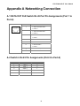
1
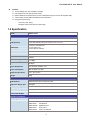
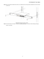
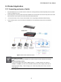
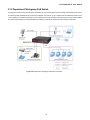
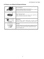
IFS ES3001-4P-4T User Manual P/N 1072680 • REV A • ISS 22OCT13 Copyright Trademarks and patents Manufacturer © 2013 United Technologies Corporation Interlogix is part of UTC Climate Controls & Security, a unit of United Technologies Corporation. All rights reserved. The IFS ES3001-4P-4T name and logo are trademarks of United Technologies. Other trade names used in this document may be trademarks or registered trademarks of the manufacturers or vendors of the respective products. Interlogix 3211 Progress Drive, Lincolnton, NC 28092 USA Authorized EU manufacturing representative: UTC Climate Controls & Security B.V., Kelvinstraat 7, 6003 DH Weert, Netherlands Intended use Certification FCC compliance ACMA compliance Canada European Union directives Contact Information Use this product only for the purpose it was designed for; refer to the data sheet and user documentation for details. For the latest product information, contact your local supplier or visit us online at www.interlogix.com. N4131 This equipment has been tested and found to comply with the limits for a Class A digital device, pursuant to part 15 of the FCC Rules. These limits are designed to provide reasonable protection against harmful interference when the equipment is operated in a commercial environment. This equipment generates, uses, and can radiate radio frequency energy and, if not installed and used in accordance with the instruction manual, may cause harmful interference to radio communications. You are cautioned that any changes or modifications not expressly approved by the party responsible for compliance could void the user's authority to operate the equipment. Notice! This is a Class A product. In a domestic environment this product may cause radio interference in which case the user may be required to take adequate measures. This Class A digital apparatus complies with Canadian ICES-003. Cet appareil numérique de la classe A est conforme á la norme NMB-003du Canada. 2004/108/EC (EMC Directive): Hereby, UTC Climate Controls & Security Corporation, Inc. declares that this device is in compliance with the essential requirements and other relevant provisions of Directive 2004/108/EC. For contact information, see www.interlogix.com or www.utcfssecurityproducts.eu. IFS ES3001-4P-4T User Manual TABLE OF CONTENTS IFS ES3001-4P-4T USER MANUAL ................................................................................1 1. INTRODUCTION ..........................................................................................................4 1.1 Checklist ...............................................................................................................................................4 1.2 Product Description.............................................................................................................................4 1.3 Features ................................................................................................................................................4 1.4 Specification.........................................................................................................................................5 2. HARDWARE DESCRIPTION .......................................................................................7 2.1 Front Panel ...........................................................................................................................................7 2.1.1 LED Indicators ............................................................................................................................. 7 2.2 Rear Panel.............................................................................................................................................8 3. HARDWARE INSTALLATION .....................................................................................9 3.1 Desktop Installation .............................................................................................................................9 3.2 Rack Mounting .................................................................................................................................. 10 3.3 Product Application .......................................................................................................................... 12 3.3.1 Connecting end node or Switch................................................................................................. 12 3.3.2 Department/ Workgroup PoE Switch......................................................................................... 13 3.4 Power over Ethernet Powered Device ............................................................................................ 14 4. POWER OVER ETHERNET OVERVIEW................................................................... 15 5. TROUBLESHOOTING................................................................................................17 APPENDIX A NETWORKING CONNECTION ............................................................... 18 A.1 DATA OUT PoE Switch RJ-45 Port Pin Assignments (Port 1 to Port-4) ..................................... 18 A.2 Switch‘s RJ-45 Pin Assignments (Port-5 to Port-8) ...................................................................... 18 A.3 RJ-45 cable pin assignment ............................................................................................................ 19 CONTACTING TECHNICAL SUPPORT ........................................................................ 20 3 IFS ES3001-4P-4T User Manual 1. Introduction 1.1 Checklist Check the contents of your package for following parts: ES3001-4P-4T x1 User's manual CD x1 Power cord x 1 If any of these pieces are missing or damaged, please contact your dealer immediately. If possible, retain the carton including the original packing material, to repack the product in case there is a need to return it to us for repair. 1.2 Product Description To fulfill the demand of sufficient PoE power for network applications with Gigabit speed transmission, the new member in the 802.3af PoE Gigabit Ethernet Switch family - ES3001-4P-4T, the 8-Port 10/100/1000Mbps with 4-Port 802.3af Power over Ethernet Switch which features high performance Gigabit IEEE 802.3af PoE (Up to 15.4 Watts) and totally 55 Watts PoE budget on half of the 10/100/1000Mbps TP ports of ES3001-4P-4T. The four 802.3af PoE ports provide PoE power injector function which is able to drive 4 IEEE 802.3af compliant powered devices. The ES3001-4P-4T also provides a simple, cost-effective, and non-blocking wire-speed performance with 10-inch metal shape for desktop deployment in compact housing, SOHO office or department network application. All RJ-45 copper interfaces in the ES3001-4P-4T support 10/100/1000Mbps Auto-Negotiation for optimal speed detection through RJ-45 Category 6, 5 or 5e cables. It also supports standard Auto-MDI/MDI-X that can detect the type of connection to any Ethernet device without requiring special straight or crossover cables. 1.3 Features ■ RJ-45 Interface 8-Port 10/100/1000Mbps Gigabit Ethernet ports 4-Port supports 48V DC power to PoE Powered Device PoE Complies with IEEE 802.3af Power over Ethernet End-Span PSE Up to 4 IEEE 802.3af devices powered Supports PoE Power up to 15.4 Watts for each PoE port Auto detect powered device (PD) Circuit protection prevents power interference between ports Remote power feeding up to 100m Switching Hardware based 10/100/1000Mbps Auto-Negotiation and Auto MDI/MDI-X Flow control for Full Duplex operation and back pressure for Half Duplex operation Integrates address look-up engine, supporting 8K absolute MAC addresses 9K Jumbo Frame supports at all speed (10/100/1000Mbps) Automatic address learning and address aging 4 IFS ES3001-4P-4T User Manual Hardware 10-inch desktop size, rack mountable; 1U height LED indicators for PoE ready and PoE activity Optional Rack Ear Accessories Kit for 10-inch cabinet (RKE-10A) and 19-inch cabinet (RKE-10B) 1 silent FAN to provide stable and efficient power performance Energy-Saving technology - Link down power saving - Intelligent scales power based on cable length 1.4 Specification Model ES3001-4P-4T Hardware Specification Network Connector 8-Port RJ-45 for 10/100/1000Base-T PoE Inject Port 4-Port with 802.3af PoE injector function, Port-1 to Port-4 LED Display 1 Power, 1 FAN Alert LED 1-4 port PoE in-use 1-8 port Speed, LNK/ACT Switch Architecture Store and Forward switch architecture MAC Address 8K MAC address table with Auto learning function Switch Fabric 16Gbps Switch Throughput 11.9 Mpps Jumbo Packet Size 9K Bytes Power Requirement AC 100~240V, 50/60Hz, 1.5A Power Consumption Max. 65 Watts / 221 BTU Dimension (W x D x H) 217 x 135 x 43 mm Weight 890g Power over Ethernet PoE Standard IEEE 802.3af Power over Ethernet / PSE PoE Power Supply Type End-Span PoE Power Output Per Port 48V DC, 350mA . Max. 15.4 Watts Power Pin Assignment 1/2(+), 3/6(-) PoE Power Budget 55 Watts Standard Conformance EMI Safety FCC Class A, CE Standard Compliance IEEE 802.3 IEEE 802.3u IEEE 802.3ab IEEE 802.3x IEEE 802.3af Ethernet Fast Ethernet Gigabit Ethernet Flow Control Power over Ethernet 5 IFS ES3001-4P-4T User Manual Environment Operating Environment 0 ~ 50 Degree C Storage Environment -40 ~ 70 Degree C Operating Humidity 5 ~ 95%, relative humidity, non-condensing Storage Humidity 5 ~ 95%, relative humidity, non-condensing 6 IFS ES3001-4P-4T User Manual 2. Hardware description This product provides three different running speeds – 10Mbps, 100Mbps and 1000Mbps in the same switch and automatically distinguishes the speed of incoming connection. This section describes the hardware features of ES3001-4P-4T. For easier management and control of the Switch, familiarize yourself with its display indicators, and ports. Front panel illustrations in this chapter display the unit LED indicators. Before connecting any network device to the ES3001-4P-4T, please read this chapter carefully. In the following section, the term “Switch” means the Switch device, ie. ES3001-4P-4T; term of “switch” can be any third switches. 2.1 Front Panel The Front Panel of the ES3001-4P-4T PoE Ethernet Switch consists of 8x Auto-Sensing 10/100/1000Mbps Ethernet RJ-45 Ports. The LED Indicators are also located on the front panel of the ES3001-4P-4T. Figure 2-1: ES3001-4P-4T Switch Front Panel 2.1.1 LED Indicators System LED PWR FAN Alert Color Green Orange Function Lights to indicate that the Switch has power. Lights to indicate that the FAN failure. Per 10/100/1000Mbps Port LED PoE In-use Speed LNK/ACT Color Function Orange Lights to indicate the port is providing 48V DC in-line power. (1-4 ports) Green Lit: indicate the Switch is successfully connecting to the network at 1000Mbps. Off: indicate that the Switch is successfully connecting to the network at 10Mbps or 100Mbps. Green Lit: indicate the link through that port is successfully established. Blinks to indicate that the Switch is actively sending or receiving data over that port. 7 IFS ES3001-4P-4T User Manual 2.2 Rear Panel The rear panel of the ES3001-4P-4T indicates an AC inlet power socket, which accepts input power from 100 to 240V AC, 50-60Hz. And have a fan hole on the rear panel. Figure 2-2: ES3001-4P-4T Switch Rear Panel The device is a power-required device, it means, it will not work till it is powered. If your networks should active all the time, please consider using UPS (Uninterrupted Power Supply) for your device. It will Power Notice: prevent you from network data loss or network downtime. In some area, installing a surge suppression device may also help to protect your ES3001-4P-4T from being damaged by unregulated surge or current to the ES3001-4P-4T or the power adapter. 8 IFS ES3001-4P-4T User Manual 3. Hardware Installation Before start up Before your installation, please refer to the followings for your cabling: 10/100/1000Base-T All 10/100/1000Base-T ports come with Auto-Negotiation capability. They automatically support 1000Base-T, 100Base-TX and 10Base-T networks. Users only need to plug a working network device into one of the 10/100/1000Base-T ports, and then turn on the ES3001-4P-4T. The port will automatically runs in 10Mbps, 20Mbps, 100Mbps or 200Mbps and 1000Mbps or 2000Mbps after the negotiation with the connected device. Cabling Each 10/100/1000Base-T ports use RJ-45 sockets -- similar to phone jacks -- for connection of unshielded twisted-pair cable (UTP). The IEEE 802.3 / 802.3u 802.3ab Fast / Gigabit Ethernet standard requires Category 5 UTP for 100Mbps 100Base-TX. 10Base-T networks can use Cat.3, 4, 5 or 1000Base-T use 5/5e/6 UTP (see table below). Maximum distance is 100meters (328 feet). Port Type Cable Type Connector 10Base-T Cat 3, 4, 5, 2-pair RJ-45 100Base-TX Cat.5 UTP, 2-pair RJ-45 1000Base-T Cat.5/5e/6 UTP, 2-pair RJ-45 Any Ethernet devices like hubs/ PCs can connect to the ES3001-4P-4T by using straight-through wires. The eight-10/100/1000Mbps ports are auto-MDI/MDI-X can be used on straight-through or crossover cable. 3.1 Desktop Installation To install the Switch on desktop, simply follow the next steps: Figure 3-1: Attaching the rubber feet to the Gigabit Ethernet Switch 9 IFS ES3001-4P-4T User Manual Step 1: Place the Switch on desktop near an AC power source. Step 2: Keep enough ventilation space between the Switch and the surrounding objects. When choosing a location, please keep in mind the environmental restrictions discussed in Chapter 1, Section 4, in Specification. Step 3: Connect your Switch to 802.3af complied Power Devices (PD) and other network devices. A. Connect one end of a standard network cable to the 10/100/1000 RJ-45 ports on the front of the Switch. B. Connect the other end of the cable to the network devices such as printer servers, workstations or routers…etc. Connection to the Switch requires UTP Category 5 network cabling with RJ-45 tips. For more information, please see the Cabling Specification in Appendix A. Step 4: Supply power to the Switch. A. Connect one end of the power cable to the Switch. B. Connect the power plug of the power cable to a standard wall outlet. When the Switch receives power, the Power LED should remain solid Green. 3.2 Rack Mounting To install the Switch in a 10-inch standard rack, follow the instructions described below. Step 1: Place your Gigabit Ethernet Switch on a hard flat surface, with the front panel positioned towards your front side. Step 2: Attach a rack-mount bracket to each side of the Switch with supplied screws attached to the package. Figure 3-1 shows how to attach brackets to one side of the Switch. Figure 3-1: Attaching the brackets to the Switch. You must use the screws supplied with the mounting brackets. Damage caused to the parts by using incorrect screws would invalidate the warranty. Step 3: Secure the brackets tightly. Step 4: Follow the same steps to attach the second bracket to the opposite side. 10 IFS ES3001-4P-4T User Manual Step 5: After the brackets are attached to the Switch, use suitable screws to securely attach the brackets to the rack, as shown in Figure 3-2. Figure 3-2: Mounting the Switch in a Rack Step 6: Proceed with steps 3 and steps 4 of session 3.1 Desktop Installation to connect the network cabling and supply power to your Switch. 11 IFS ES3001-4P-4T User Manual 3.3 Product Application 3.3.1 Connecting end node or Switch 1. Place the ES3001-4P-4T on a smooth surface or fasten the mounting brackets purchased separately with the provided screws in a standard 19” rack. 2. Connect the power cord to the power inlet socket of ES3001-4P-4T and the other end into the local power source outlet. When the Switch receives power, the Power LED should remain solid Green. 3. 4. Connect other switch or PC to one port of the ES3001-4P-4T using Category 3/4/5/5e/6 UTP/STP cabling. Connect another switch or PC to the other port of ES3001-4P-4T by following the same process as described in Step 3. Figure 3-3: End node or Switch Connection Cable distance for Switch The cable distance between the ES3001-4P-4T and PC should not exceed 100 meter for UTP/STP cable. Make sure the wiring is correct It can be used Category 3/4/5 cable in 10Mbps operation. To reliably operate your network at 100Mbps or 1000Mbps, you must use an Unshielded Twisted-Pair (UTP) Category 5/5e/6 cable, or better Data Grade cabling. While a Category 3 or 4 cables may initially seem to work, it will soon cause data loss. 12 IFS ES3001-4P-4T User Manual 3.3.2 Department/ Workgroup PoE Switch Providing 4-Port PoE in-line power interface, the ES3001-4P-4T can easily build a power centrally-controlled IP phone system, IP Camera system and Wireless AP group for the enterprise. For instance, up to 4 cameras can be installed around the corner in the company for surveillance demands or up to 4 Wireless AP to build a wireless roaming environment in the office. Without the power-socket limitation, the Switch makes the installation of cameras or Wireless AP more easily and efficiently. Figure 3-4: Department / Workgroup PoE Switch Connection 13 IFS ES3001-4P-4T User Manual 3.4 Power over Ethernet Powered Device Voice over IP phones 3~5 Watts Enterprise can install POE VoIP Phone, ATA and other Ethernet/non-Ethernet end-devices to the central where UPS is installed for un-interrupt power system and power control system. Wireless LAN Access Points 6~12 Watts Museum, Sightseeing, Airport, Hotel, Campus, Factory, Warehouse can install the Access Point any where with no hesitation. IP Surveillance 10~12 Watts Enterprise, Museum, Campus, Hospital, Bank, can install IP Camera without limits of install location – no need electrician to install AC sockets. PoE Splitter 3~12 Watts PoE Splitter split the PoE 52V DC over the Ethernet cable into 5/12V DC power output. It frees the device deployment from restrictions due to power outlet locations, which eliminate the costs for additional AC wiring and reduces the installation time. 14 IFS ES3001-4P-4T User Manual 4. Power OVER Ethernet Overview What is PoE? Based on the global standard IEEE 802.3af, PoE is a technology for wired Ethernet, the most widely installed local area network technology adopted today. PoE allows the electrical power necessary for the operation of each end-device to be carried by data cables rather than by separate power cords. New network applications, such as IP Cameras, VoIP Phones, and Wireless Networking, can help enterprises improve productivity. It minimizes wires that must be used to install the network for offering lower cost, and less power failures. IEEE 802.3af also called Data Terminal equipment (DTE) power via Media dependent interface (MDI) is an international standard to define the transmission for power over Ethernet. The 802.3af is delivering 48V power over RJ-45 wiring. Besides 802.3af also define two types of source equipment: Mid-Span and End-Span. Mid-Span Mid-Span device is placed between legacy switch and the powered device. Mid-Span is tap the unused wire pairs 4/5 and 7/8 to carry power, the other four is for data transmit. End-Span End-Span device is direct connecting with power device. End-Span could also tap the wire 1/2 and 3/6. PoE System Architecture The specification of PoE typically requires two devices: the Powered Source Equipment (PSE) and the Powered Device (PD). The PSE is either an End-Span or a Mid-Span, while the PD is a PoE-enabled terminal, such as IP Phones, Wireless LAN, etc. Power can be delivered over data pairs or spare pairs of standard CAT-5 cabling. How Power is Transferred Through the Cable A standard CAT5 Ethernet cable has four twisted pairs, but only two of these are used for 10BASE-T and 100BASE-T. The specification allows two options for using these cables for power, shown in Figure 2 and Figure 3: The spare pairs are used. Figure 2 shows the pair on pins 4 and 5 connected together and forming the positive supply, and the pair on pins 7 and 8 connected and forming the negative supply. (In fact, a late change to the spec allows either polarity to be used). Figure 4-1 - Power Supplied over the Spare Pins The data pairs are used. Since Ethernet pairs are transformer coupled at each end, it is possible to apply DC power to the center tap of the isolation transformer without upsetting the data transfer. In this mode of operation the pair on pins 3 and 6 and the pair on pins 1 and 2 can be of either polarity. 15 IFS ES3001-4P-4T User Manual Figure 4-2 - Power Supplied over the Data Pins When to install PoE? Consider the following scenarios: • You're planning to install the latest VoIP Phone system to minimize cabling building costs when your company moves into new offices next month. • The company staff has been clamoring for a wireless access point in the picnic area behind the building so they can work on their laptops through lunch, but the cost of electrical power to the outside is not affordable. • Management asks for IP Surveillance Cameras and business access systems throughout the facility, but they would rather avoid another electrician's payment. References: IEEE Std 802.3af-2003 (Amendment to IEEE Std 802.3-2002, including IEEE Std 802.3ae-2002), 2003 Page(s):0_1-121 White Paper on Power over Ethernet (IEEE 802.3af) 16 IFS ES3001-4P-4T User Manual 5. Troubleshooting This chapter contains information to help you solve problems. If the Switch is not functioning properly, make sure the Ethernet Switch was set up according to instructions in this manual. The Link LED is not lit Solution: Check the cable connection and remove duplex mode of the Switch. Performance is bad Solution: Check the full duplex status of the Switch. If the Ethernet Switch is set to full duplex and the partner is set to half duplex, then the performance will be poor. 100Base-TX port link LED is lit, but the traffic is irregular Solution: Check that the attached device is not set to dedicate full duplex. Some devices use a physical or software switch to change duplex modes. Auto-negotiation may not recognize this type of full-duplex setting. Why the Switch doesn’t connect to the network Solution: Check the LNK/ACT LED on the switch Try another port on the Switch Make sure the cable is installed properly Make sure the cable is the right type Turn off the power. After a while, turn on power again. Why I connect my PoE device to ES3001-4P-4Tand it cannot power on? Solution: 1. Please check the cable type of the connection from FSD-804(port 1 to port 4) to the other end. The cable should be an 8-wire UTP, Category 5 or above, EIA568 cable within 100 meters. A cable with only 4-wire, short loop or over 100 meters, all will affect the power supply. 2. Please check and assure the device that fully complied with IEEE 802.3af standard. What is the power output of each IEEE 802.af PoE port? Solution: Each PoE port supports 48VDC, 350mA, max 15.4 watts power output. Detect and inject by the standard of IEEE 802.3af. 17 IFS ES3001-4P-4T User Manual Appendix A Networking Connection A.1 DATA OUT PoE Switch RJ-45 Port Pin Assignments (Port 1 to Port-4) PIN NO 1 RJ-45 SIGNAL ASSIGNMENT Output Transmit Data + Power + 2 Output Transmit Data – Power + 3 Receive Data + Power - 4 - 5 - 6 Receive Data – Power - 7 - 8 - A.2 Switch‘s RJ-45 Pin Assignments (Port-5 to Port-8) Contact MDI MDI-X 1 1 (TX +) 3 2 2 (TX -) 6 3 3 (RX +) 1 6 6 (RX -) 2 4, 5, 7, 8 Not used Not used 18 IFS ES3001-4P-4T User Manual A.3 RJ-45 cable pin assignment 6 321 6 321 6 3 21 There are 8 wires on a standard UTP/STP cable and each wire is color-coded. The following shows the pin allocation and color of straight cable and crossover cable connection: Straight Cable 1 2 3 4 5 6 SIDE 1 7 8 SIDE 1 SIDE 2 1 2 3 4 5 6 7 8 Straight Cable 1 2 3 4 5 6 8 SIDE 1 SIDE 2 1 2 3 4 5 6 1 = White / Orange 1 = White / Orange 2 = Orange 2 = Orange 3 = White / Green 3 = White / Green 4 = Blue 4 = Blue 5 = White / Blue 5 = White / Blue 6 = Green 6 = Green 7 = White / Brown 7 = White / Brown 8 = Brown 8 = Brown SIDE 1 7 7 8 SIDE2 SIDE2 1 = White / Orange 1 = White / Orange 2 = Orange 2 = Green 3 = White / Green 3 = White / Orange 4 = Blue 4 = Blue 5 = White / Blue 5 = White / Blue 6 = Green 6 = Orange 7 = White / Brown 7 = White / Brown 8 = Brown 8 = Brown Figure A-1: Straight-Through and Crossover Cable Please make sure your connected cables are with same pin assignment and color as above picture before deploying the cables into your network. 19 IFS ES3001-4P-4T User Manual Contacting Technical Support Contact technical support if you encounter any difficulties during this installation. Please make sure you have the requested diagnostic or log files ready before you contact us by phone or go to www.interlogix.com/customer-support. Technical Support Europe, Middle East and Africa W Select Contact Us at www.utcfssecurityproducts.eu North America T +1 855.286.8889 E [email protected] Australia E [email protected] 20