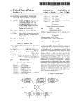
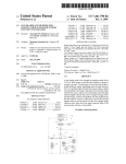
1
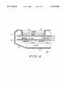
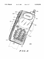
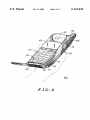
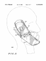
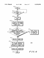
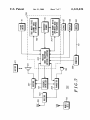
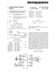
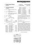
US006141436A
United States Patent [19]
[11] Patent Number:
Srey et al.
[45]
[54]
PORTABLE COMMUNICATION DEVICE
HAVING A FINGERPRINT IDENTIFICATION
SYSTEM
[75]
Inventors: Lena Srey, Chicago; Mark William
Pod], Bartlett; Kevin D. Kaschke,
Oct. 31, 2000
OTHER PUBLICATIONS
StarTACTM90 Wearable Cellular Telephone User Manual,
1995, Motorola, Pan American Cellular Subscriber Group,
600 North US. Highway 45, Libertyville, Illinois 60048, pp.
2, 3 and 84—99
P .
Hoffman Estates, all of Ill.
Date of Patent:
6,141,436
E
nmary
.
J
L C
xammer— Ose
'
Ouso
Assistant Examiner—ShaWn B. Cage
Attorney, Agent, or Firm—Kevin D. Kaschke; Paul J.
[73] Assignee: Motorola, Inc., Schaumburg, Ill.
Barmsiak
[57]
ABSTRACT
[21] APPL NO; 09/047,773
A portable communication . device (100, 300, 400, 500)
[22]
[51]
52
Flled?
Mar- 25, 1998
Int Cl 7
G06K 9/00 607D 7/00
Us‘ Ci """""""""""""""" "
382/124? 340/825 34
a scanner (115) for scanning a ?ngerprint (123) of a ?nger
(121) to generate an image of the ?ngerprint (123). In a ?rst
embodiment, the scanner (115) is positioned relative to a
[
I. .
. ..................................... ..
Fleld Of Search
.................... ......... ..
Switch (201) on the device (100, 300, 400, 500) to permit the
?nger
to generate the actuation force for the Switch
_
]
comprises a ?ngerpr1nt1dent1?cat1on system (709) including
,
.
382/127’ 380/23’ 30’ 340/825'3Al’ 825'69’
(201) When the ?ngerprint (123) is positioned on the scanner
825'72’ 348/552
(115). In a second embodiment, the scanner (115) is ergo
nomically positioned on a housing (113, 117, 119) of the
,
[56]
References C‘ted
US PATENT DOCUMENTS
device (100, 300, 400, 500) Where the ?nger (121) or a
thumb naturally rests on the housing (113, 117, 119) When
the person holds the housing (113, 117, 119) While the device
?llffay .................................... ..
,
,
urray
. . . . .
475777345 3/1986 Abramov
5 591 949 1/1997 Bernstein
58387306 11/1998 O’Connor
5,870,672
. . . . ..
is in use‘ In a third embodiment, a
-
-
transmitter (205) of the device (100, 300, 400, 500) trans
mits data representative of the image of the ?ngerprint (123)
to a remote site (715) When data representative of the image
2/1999 StOddard et al. ..................... .. 455/410
Ofthe ?ngerprint (123) does not mateh data representative of
a reference ?ngerprint.
FOREIGN PATENT DOCUMENTS
5-095329
_
382/124
235/380
382/124
4/1993
Japan ............................. .. H04B 7/26
5 Claims, 7 Drawing Sheets
U.S. Patent
0a. 31, 2000
Sheet 1 of7
FIG .1
6,141,436
U.S. Patent
0a. 31, 2000
Sheet 2 of7
6,141,436
11\5
SCANNER
l
I
’
l
SWITCH
217 JR
‘ l77777/l/l/l/l/l/l/ /// /////!/1'~21,3
‘
119
PROCESSOR
A203
CONNECTOR
Z///////// /////////////// I//
TRANSMITTER
a
.
RECEIVER
\205
I
207
211
FIG.2
209
215
U.S. Patent
0a. 31, 2000
Sheet 3 of7
6,141,436
U.S. Patent
0a. 31, 2000
Sheet 4 of7
6,141,436
N
/
/
m
U.S. Patent
FIG.5
0a. 31, 2000
Sheet 5 of7
6,141,436
U.S. Patent
0a. 31, 2000
Sheet 6 of7
6,141,436
601
603
FINGER
PRINT PRESENT 0N
SCANNER
605
SCAN FINGER
PRINT
60 7l
STORE DATE REPRESENTING
AN IMAGE OF THE SCANNED
FINGER PRINT IN A FIRST
NENORY DEVICE.
DOES
THE DATA
REPRESENTING THE SCANNED
FINGERPRINT INAGE HATCH DATA
REPRESENTING A REFERENCE FINGERPRINT
IMAGE STORED IN A
SECOND MEMORY
DEVICE
?
609
ENABLE CIRCUITRY
IN THE DEVICE
FOR NORMAL usa
OF THE DEVICE
I TURN ON A TRANSMITTER I
615\
SEND THE DATA REPRESENTING
THE SCANNED FINGERPRINT
INAGE AND THE LOCATION OF
THE DEVICE TO A REMOTE SITE
6T7\
TURN OFF THE TRANSMITTER
FIG.6
U.S. Patent
0a. 31, 2000
Sheet 7 of7
6,141,436
..
53>E
:25
EH?oz: 5 28
2:aMs2; azs:araga:
5xon9$235605m: a2s5: 2a5 2:
>
EN
52% A5285%:Q252
R
2mcit;
55:SNA
rgw
_
J$.r
I|5 5:
2K
U
2mgA.52
| l_
5@28;:
555 “0E2:5
>55;tw
l
I
l
I
I
l
l
l
l
l
l
l
l
l
l
l
I
l
I
zsazzol
'h.
RN
N
Q
m2Eg
meSN8“
52m E5
6,141,436
1
2
PORTABLE COMMUNICATION DEVICE
HAVING A FINGERPRINT IDENTIFICATION
SYSTEM
tems are knoWn in the art as exempli?ed by US. Pat. Nos.
5,473,144, 5,493,621, 5,546,471, 5,426,708, 5,465,303,
5,467,403, and 5,493,621 and by a ?ngerprint veri?er avail
able from VLSI Vision Limited, 18805 Cox Avenue, Suite
260, Saratoga, Calif. 95070, USA. Fingerprint identi?cation
FIELD OF THE INVENTION
systems typically comprise a ?ngerprint scanner for scan
The present invention generally relates to portable com
ning a ?ngerprint, a read only memory (ROM) lookup table
munication devices and more particularly to a portable
for storing data representative of an authoriZed user’s
communication device having a ?ngerprint identi?cation
system.
10
?ngerprint, a digital signal processor (DSP) having an
algorithm for comparing the scanned ?ngerprint With the
data representing an authoriZed user’s ?ngerprint. A ?nger
BACKGROUND OF THE INVENTION
print identi?cation system advantageously provides unique
Portable communication devices, such as cellular
telephones, are Well knoWn in the art and permit a user to
personal user identi?cation. HoWever, ?ngerprint identi?
cation system have not been applied to portable communi
communicate With a remote site. Typically, a user pays a fee 15 cation devices.
to a communications service provider for access to a com
Accordingly, there is a need for a portable communication
munication system in Which the portable communication
device operates. Cellular telephones, in particular, have
device having a ?ngerprint identi?cation system.
BRIEF DESCRIPTION OF THE DRAWINGS
become so popular that thieves have found it pro?table to
steal these devices for their oWn use or for sale to another 20
user.
To discourage the thieves and to generally provide elec
present invention.
tronic security, most cellular telephones permit a user to
enter a code to electronically lock and/or unlock a cellular
telephone. Electronically locking a cellular telephone pro
FIG. 2 illustrates a cross-sectional vieW of a portion of a
25
hibits the cellular telephone from being used, such as to
second embodiment the present invention.
30
FIG. 5 illustrates a perspective vieW of a portable com
munication device in accordance With a third aspect of a
Several knoWn techniques for generating an electronic
35
the cellular telephone labeled “FCN” (i.e. function) folloWed
by pressing another key on the keypad of the cellular
telephone labeled “5,” for example, pressing a predeter
mined sequence of numerically labeled keys on a keypad of
the cellular telephone, such as for example, by pressing the
keys “5,” “3,” and “8,” and selecting a lock feature from a
menu presented in an electronic display.
One knoWn technique for generating an electronic unlock
code include: pressing a predetermined sequence of numeri
FIG. 6 illustrates a ?oWchart describing a method per
40
With a third embodiment the present invention.
FIG. 7 illustrates an electrical block diagram a portable
communication device in accordance With the ?rst, the
second and the third embodiments the present invention.
45
The predetermined sequence of numerically labeled keys
may be the same or different for electronically locking and
50
telephone to generate an electronic lock or an unlock code
include: the electronic unlock and lock code may be used by
someone other than the authoriZed user, if the electronic
unlock and lock code is knoWn to the unauthoriZed user;
second embodiment the present invention.
formed by a portable communication device in accordance
cally labeled keys on a keypad of the cellular telephone,
such as for example, by pressing the keys “5,” “3,” and “8.”
unlocking a cellular telephone.
Disadvantages using keys on a keypad of the cellular
FIG. 4 illustrates a perspective vieW of a portable com
munication device in accordance With a second aspect of a
second embodiment the present invention.
phone.
lock code include: pressing a key on a keypad of the cellular
telephone labeled “LOCK,” pressing a key on a keypad of
portable communication device of FIG. 1 in accordance With
the ?rst embodiment the present invention.
FIG. 3 illustrates a perspective vieW of a portable com
munication device in accordance With a ?rst aspect of a
make or receive telephone calls and/or to enable or disable
particular features of the cellular telephone. Electronically
unlocking a cellular telephone permits the cellular telephone
to be used, such as to make or receive telephone calls and/or
to enable or disable particular features of the cellular tele
FIG. 1 illustrates a perspective vieW of a portable com
munication device in accordance With a ?rst embodiment the
55
DETAILED DESCRIPTION OF THE
PREFERRED EMBODIMENTS
In FIGS. 1—7, like reference numbers represent the same
element for feature. FIG. 1 illustrates a perspective vieW of
a portable communication device 100 in accordance With a
?rst embodiment the present invention. FIG. 2 illustrates a
cross-sectional vieW of a portion of a portable communica
tion device 100 of FIG. 1 in accordance With the ?rst
embodiment the present invention. The portable communi
cation device 100 generally includes an earpiece transducer
101, a microphone transducer 103, a display 105, a keypad
107, an antenna 109, a volume sWitch 111, a battery housing
needing to press the predetermined number of keys; needing
113, a ?ngerprint identi?cation system 709 (see FIG. 7)
to remember the electronic unlock and lock code; needing to
including a scanner 115, a front housing 117 and a rear
conceal the pressing of the predetermined number of keys at
appropriate times; needing to generate the electronic unlock
and lock code before and after, respectively, the cellular
housing 119. The design of portable communication device
100 including all of the elements mentioned hereinabove,
With the exception of the ?ngerprint identi?cation system
60
telephone is used, such as to make or receive telephone calls
and/or to enable or disable particular features of the cellular
telephone; and needing to press one key to poWer on the
709 including a scanner 115, is Well knoWn in the art and is
shoWn in US. Pat. No. Des. 384,952. The circuitry for the
portable communication device 100 Will be discussed herein
cellular phone folloWed by the predetermined number of
keys to generate an electronic lock or an unlock code.
Outside of the art of portable communication devices,
such as cellular telephones, ?ngerprint identi?cation sys
beloW With reference to FIG. 7.
65
The portable communication device 100 advantageously
uses the ?ngerprint identi?cation system 709 including the
scanner 115 as a substitute for the combination key press
6,141,436
3
4
sequence of the prior art to generate a lock code and/or an
scanner 115. Therefore, the operation of the scanner 115 and
the operation of the sWitch 201 are advantageously inte
grated or combined to provide more ef?cient use of each
unlock code for the portable communication device 100. The
?ngerprint identi?cation system advantageously provides
unique personal identi?cation characteristic of a person’s
?ngerprint; Whereas, the combination key press sequence of
the prior art provides a unique key press sequence. Disad
vantages of the combination key press sequence of the prior
operation, thereby simplifying the use of the portable com
munication device 100.
Referring to FIG. 2, the sWitch 201 is disposed underneath
the scanner 115 to permit the scanner 115 to directly actuate
art to generate a lock code and/or an unlock code include:
the electronic unlock and lock code may be used by someone
other than the authoriZed user, if the electronic unlock and
lock code is knoWn to the unauthoriZed user; needing to
press the predetermined number of keys; needing to remem
ber the electronic unlock and lock code; needing to conceal
the pressing of the predetermined number of keys at appro
priate times; needing to generate the electronic unlock and
lock code before and after, respectively, the cellular tele
phone is used, such as to make or receive telephone calls
and/or to enable or disable particular features of the cellular
the sWitch 201 When the ?nger 121 pressed doWn on the
scanner 115. The sWitch 201 is mounted on a printed circuit
10
offset from the scanner and not disposed beneath the scanner
115. In this case, a mechanism Would be needed to transfer
the actuation force applied to the scanner 115 to the sWitch
15
?nger 121 is on the scanner 115 instead of pressing the
scanner 115.
20
keys to generate an electronic lock or an unlock code.
HoWever, the ?ngerprint identi?cation system only recog
niZes unique personal ?ngerprints of a person to provide
increased security against fraudulent use of the portable
communication device 100. Therefore, the person no longer
25
need to remember the electronic unlock and lock code; to
conceal the pressing of the predetermined number of keys at
appropriate times; to generate the electronic unlock and lock
code before and after, respectively, the cellular telephone is
used, such as to make or receive telephone calls and/or to
enable or disable particular features of the cellular tele
phone; and to press one key to poWer on the cellular phone
30
an electronic lock or an unlock code. The person simply
35
The portable communication device 100 is preferably a
tion device may also be a selective call receiver, such as a
40
disposed on top of the scanner as opposed to beloW or offset
to the side of the scanner 115, as discussed hereinabove.
217 are preferably connected to the scanner 115.
Alternatively, the posts may be connected to the keypad
printed circuit board 213, to the sWitch 201, or be connected
housing 117 or an elastomeric keypad of the keypad 107.
Preferably, the scanner 115 scans the ?ngerprint 123 at the
same time as the sWitch 201 is actuated by the actuation
force eXerted by the ?nger 121. Alternatively, the scanning
access device, an email access device, or the like.
may be performed before or after the actuation of the sWitch.
The ?ngerprint identi?cation system 709, alone, is Well
Preferably, the scanning and sWitch actuation to generate the
knoWn in the art as is taught by US. Pat. Nos. 5,473,144,
5,493,621, 5,546,471, 5,426,708, 5,465,303, 5,467,403, and
Alternatively, the sWitch may be an elastomeric sWitch
integrated With the keypad or a touchscreen pad. The elas
tomeric sWitch is preferably implemented as a pushbutton
sWitch, as is Well knoWn in the art. The touchscreen pad is
preferably a transparent pad located on top of a scanning
surface of the scanner. Therefore, the touchscreen pad is
to or integrated With a separate piece, such as the front
cellular radiotelephone. HoWever, the portable communica
pager, a personal notebook, a personal computer, a personal
organiZer, a data terminal, a tWo-Way radio, an internet
Preferably, the sWitch is a microsWitch sensitive to the
movement of the scanner 115. The microsWitch may be
implemented as a pushbutton sWitch or a slide sWitch.
FIG. 2 also shoWs posts 217 disposed betWeen the scanner
and a keypad printed circuit board 213 to prevent excessive
force by a ?nger from damaging the sWitch 201. The posts
folloWed by the predetermined number of keys to generate
places their ?nger on the scanner 115 to permit the scanner
to scan their ?ngerprint.
201. Further, the sWitch may be actuated by a sliding motion
instead of a pressing motion. In this case, the ?nger 121
Would slide the scanner to actuate the sWitch 201 While the
telephone; and needing to press one key to poWer on the
cellular phone folloWed by the predetermined number of
board 213 as Well as the keypad circuitry for the keypad 107.
Alternatively, the sWitch 201 may be positioned at a location
45
input signal 711 happens in a relatively short period of time,
5,493,621 and by a ?ngerprint veri?er available from VLSI
such as one to tWo seconds, so that the user perceives the
Vision Limited, 18805 Cox Avenue, Suite 260, Saratoga,
Calif. 95070, USA. The ?ngerprint identi?cation system
portable communication device 100 as simple and conve
nient to use.
Also shoWn in FIG. 2 are a cross-sectional vieW of the
typically comprise a ?ngerprint scanner 115 for scanning a
?ngerprint, a read only memory (ROM) lookup table for
50
storing data representative of an authoriZed user’s
circuit board 215, the circuitry 700 including a processor
?ngerprint, a digital signal processor (DSP) having an
algorithm for comparing the scanned ?ngerprint With the
data representing an authoriZed user’s ?ngerprint. These
elements Will be discussed in further detail With reference to
203, a transmitter 205, a receiver 207 and a connector 209,
and a battery. The sWitch 201 is preferably mounted on the
55
keypad printed circuit board 213. The processor 203, the
transmitter 205 and the receiver 207 are preferably mounted
on the circuitry printed circuit board 215. The connector 209
connects the sWitch 201 on the keypad printed circuit board
213 to the circuitry 700 on the circuitry printed circuit board
FIG. 7 hereinbeloW.
In the ?rst embodiment, a portable communication device
100 comprises a sWitch 201 (see FIG. 2), circuitry 700 (see
FIG. 7) and a ?ngerprint identi?cation system 709. The
sWitch 201 generates an input signal 711 responsive to an
actuation force. The circuitry 700 is adapted to receive the
front housing 117, the rear housing 119, the battery housing
113, the keypad printed circuit board 213, a circuitry printed
60
215. Alternatively, the sWitch 201, the processor 203, the
transmitter 205 and the receiver 207 may be mounted on a
input signal 711. The ?ngerprint identi?cation system 709
single printed circuit board to eliminate one printed circuit
includes the scanner 115 for scanning a ?ngerprint 123 of a
board and the connector 209.
Referring brie?y to FIG. 7, the ?ngerprint identi?cation
?nger 121 to generate an image of the ?ngerprint 123. The
scanner 115 is positioned relative to the sWitch 201 such that
the ?nger 121 is permitted to generate the actuation force for
the sWitch 201 When the ?ngerprint 123 is positioned on the
65
system 709 further comprises a ?rst memory device 705, a
second memory device 707 and the processor 203 (also
shoWn in FIG. 2). The ?rst memory device 705 stores data
6,141,436
5
6
representative of the image of the ?ngerprint 123. The
sWitch 201 When the ?ngerprint 123 is positioned on the
second memory device 707 stores data representative of at
least one reference ?ngerprint. The processor 203 deter
representative of the image of the ?ngerprint 123. The
scanner 115. The ?rst memory device 705 stores data
second memory device 707 stores data representative of at
least one reference ?ngerprint. The processor 203 deter
mines Whether the data representative of the image of the
?ngerprint 123 matches the data representative of the at least
one reference ?ngerprint. The processor 203 places the
circuitry 700 in a ?rst mode responsive to the input signal
711 When the data representative of the image of the
?ngerprint 123 matches the data representative of the at least
one ?ngerprint.
The ?rst memory device 705 is preferably a random
access memory (RAM), as is Well knoWn in the art. The
second memory device 707 is preferably a read only
memory (ROM), as is Well knoWn in the art. The processor
203 is preferably a digital signal processor, as is Well knoWn
in the art. The processor 203 has contained therein a match
ing algorithm embodied in softWare or hardWare to deter
10
123 matches the data representative of the at least one
reference ?ngerprint. Further, the processor 203 places the
circuitry 700 in a second mode responsive to the poWer
on/off signal 711 When the data representative of the image
15
of the ?ngerprint 123 does not match the data representative
of the at least one ?ngerprint. Details of the ?rst and second
modes are discussed hereinabove.
In summary of a second aspect of the ?rst embodiment,
mine Whether the data representative of the image of the
?ngerprint 123 matches the data representative of the at least
the portable communication device 100 comprises the data
sWitch 201, the circuitry 700 and the ?ngerprint identi?ca
one reference ?ngerprint, as is Well knoWn in the art.
tion system 709. The data sWitch 201 generates an data
Preferably, the processor 203 places the circuitry 700 in a
second mode responsive to the input signal 711 When the
data representative of the image of the ?ngerprint 123 does
signal 711 responsive to an actuation force. The circuitry
700 is adapted to receive the data signal 711. The ?ngerprint
identi?cation system 709 comprises the scanner 115, the ?rst
not match the data representative of the at least one reference
?ngerprint.
mines Whether the data representative of the image of the
?ngerprint 123 matches the data representative of the at least
one ?ngerprint. The processor 203 places the circuitry 700
in a ?rst mode responsive to the poWer on/off signal 711
When the data representative of the image of the ?ngerprint
25
memory device 705, the second memory device 707 and the
processor 203. The scanner 115 scans the ?ngerprint 123 of
Preferably, the sWitch 201 is a poWer sWitch and the input
signal 711 is a poWer on/off signal. In this case, ?rst mode
the ?nger 121 to generate an image of the ?ngerprint 123.
and the second mode preferably comprise the circuitry 700
being turned on and the circuitry 700 being prevented from
being turned on, respectively. Alternatively, the ?rst mode
and the second mode may comprise the circuitry 700 being
such that the ?nger 121 is permitted to generate the actuation
force for the data sWitch 201 When the ?ngerprint 123 is
The scanner 115 is positioned relative to the data sWitch 201
positioned on the scanner 115. The ?rst memory device 705
stores data representative of the image of the ?ngerprint 123.
turned on and the circuitry 700 temporarily being turned on
to transmit the data representative of the image of the
?ngerprint to a remote site then the circuitry 700 being
turned off, respectively. This alternative Will be discussed in
further detail With reference to FIG. 6.
Alternatively, the sWitch 201 is a data sWitch and the input
signal is a data signal. In this case, the ?rst mode and the
second mode further comprise an operational mode of the
The second memory device 707 stores data representative of
at least one reference ?ngerprint. The processor 203 deter
mines Whether the data representative of the image of the
?ngerprint 123 matches the data representative of the at least
one reference ?ngerprint. The processor 203 places the
circuitry 700 in a ?rst mode responsive to the data signal 711
When the data representative of the image of the ?ngerprint
123 matches the data representative of the at least one
circuitry 700 being enabled and the operational mode of the
?ngerprint. Further, the processor 203 places the circuitry
circuitry 700 being disabled, respectively. Preferably, the
700 in a second mode responsive to the data signal 711 When
operational mode of the circuitry 700 further comprises an
incoming signal responding mode, such as ansWering an
incoming telephone call by pressing a “SEND” key on a
cellular telephone. Alternatively, in this case the operational
mode of the circuitry 700 may comprises a customiZed
feature setting mode, Wherein the person is permitted to
change operational features or options of the portable com
the data representative of the image of the ?ngerprint 123
45
munication device 100.
Note that any of the features of the ?rst embodiment may
be used individually or in combination to achieve various
mechanical structures, electrical structures and methods of
accordance With a ?rst aspect of a second embodiment the
present invention. FIG. 4 illustrates a perspective vieW of a
portable communication device 400 in accordance With a
second aspect of the second embodiment the present inven
tion. FIG. 5 illustrates a perspective vieW of a portable
operation of the portable communication device 100.
In summary of one aspect of the ?rst embodiment, the
55
portable communication device 100 comprises the poWer
sWitch 201, the circuitry 700 and the ?ngerprint identi?ca
communication device 500 in accordance With a third aspect
of the second embodiment the present invention.
In accordance With the second embodiment, the portable
communication device 300, 400 or 500 comprises circuitry
700 (see FIG. 7), a housing 117 and 119 and the ?ngerprint
tion system 709. The poWer sWitch 201 generates a poWer
on/off signal 711 responsive to an actuation force. The
identi?cation system 709 (see FIG. 7). The housing 113, 117
circuitry 700 is adapted to receive the poWer on/off signal
711. The ?ngerprint identi?cation system 709 comprises the
and 119 carries the circuitry 700. The housing 117 and 119
is adapted to be held by a hand, having ?ngers and a thumb,
scanner 115, the ?rst memory device 705, the second
memory device 707 and the processor 203. The scanner 115
scans the ?ngerprint 123 of the ?nger 121 to generate the
image of the ?ngerprint. The scanner 115 is positioned
relative to the poWer sWitch 201 such that the ?nger 121 is
permitted to generate the actuation force for the power
does not match the data representative of the at least one
?ngerprint. Details of the ?rst and second modes are dis
cussed hereinabove.
Turning noW to FIGS. 3, 4 and 5, as second embodiment
of the present invention is presented. FIG. 3 illustrates a
perspective vieW of a portable communication device 300 in
65
of a person. The ?ngerprint identi?cation system 709
includes the scanner 115 for scanning an image of the
?ngerprint 123 of the ?nger 121 or the thumb of the hand.
The scanner 115 is ergonomically positioned on the housing
113, 117 and 119 Where the ?nger 121 or thumb naturally
6,141,436
7
8
rests on the housing 113, 117 and 119 When the person holds
structions as shoWn in FIGS. 3, 4 and 5. For example, the
the housing 113, 117 and 119 While the portable communi
scanner 115 may be located on the side surface 305 of the top
housing 501 in FIG. 5 or the scanner 115 may be located on
cation device 300, 400 or 500 is in use. The second embodi
ment advantageously permits a person to grab and hold the
portable communication device 300, 400 or 500 in a natural
the right side surface of the housing 113, 117, and 119 in
Way and at the same time use the scanner 115. The ergo
In accordance With the second embodiment, the ?nger
print identi?cation system 709 further comprises the ?rst
FIG. 4.
nomic position of the scanner 115 advantageously saves the
person time in operating the portable communication device
memory device 705, the second memory device 707 and the
processor 203. The ?rst memory device 705 stores data
300, 400 or 500 by placing the scanner 115 in a location that
the person can easily reach While holding the portable
communication device 300, 400 or 500. The ergonomic
position of the scanner 115 advantageously also permits the
10
representative of the image of the ?ngerprint 123. The
second memory device 707 stores data representative of at
least one reference ?ngerprint. The processor 203 deter
person to use the portable communication device 300, 400
rear surface 303. The front surface 301 typically has a user
mines Whether the data representative of the image of the
?ngerprint 123 matches the data representative of the at least
one reference ?ngerprint. The processor 203 places the
circuitry 700 in a ?rst mode responsive to the input signal
711 When the data representative of the image of the
?ngerprint 123 matches the data representative of the at least
one reference ?ngerprint. Preferably, the processor 203
permits the circuitry 700 to operate in the ?rst mode as long
interface including the earpiece transducer 101, the micro
phone transducer 103, the display 105 and the keypad 107.
as the ?nger 121 or thumb remains on the scanner 115.
Preferably, the scanner 115 scans the ?ngerprint to detect an
or 500 and the scanner 115 carried thereon With one hand,
thereby permitting the person to use their other hand for
other things.
15
Preferably, the housing 113, 117 and 119 has a front
surface 301 disposed opposite a rear surface 303 and a side
surface 305 disposed betWeen the front surface 301 and the
The rear surface 303 of the housing 113, 117 and 119
authoriZed user only once, then periodically checks for the
typically encloses the battery 211 (see FIG. 2). Alternatively,
presence of the ?ngerprint Without engaging the matching
the housing 113, 117 and 119 may be constructed as a single
25
housing. Further, the battery may cover only a portion of the
rear surface of the battery housing 119. In this case, the
algorithm in the processor 203.
Preferably, the circuitry 700 includes a transmitter 205
scanner 115 is located on the rear surface of the rear housing
coupled to a microphone transducer 103 and a receiver 207
coupled to an earpiece transducer 101, as shoWn in FIG. 7.
119 and not on the battery housing 113 to avoid the need for
connecting the scanner 115 to the circuitry 700 through the
hand of the person against a head of the person to permit the
The housing 113, 117 and 119 is adapted to be held by the
battery housing 113.
person to listen to acoustic signals generated by the earpiece
transducer 101 and to generate acoustic signals for input into
the microphone transducer 103 While the portable commu
According to a ?rst aspect of the second embodiment, the
scanner 115 is ergonomically positioned on the side surface
305 of the housing 113, 117 and 119, as shoWn in FIGS. 3
nication device 300, 400 and 500 is in use. When the
and 4. In FIG. 3, the scanner 115 is positioned on a left side 35 portable communication device 300, 400 and 500 is held in
this position, the scanner 115 is located in advantageous
of the housing 113, 117 and 119 to permit the ?nger of a
person’s right hand to be positioned on the scanner 115 When
locations as described hereinabove.
FIG. 6 illustrates a ?oWchart describing a method per
the portable communication device 300 is held by the
person’s right hand during use. The design of the housing
formed by a portable communication device 100, 200, 300,
113, 117 and 119 shoWn in FIG. 3, With the exception of the
400, or 500 in accordance With a third embodiment the
scanner 115 and the location thereof, is shoWn in US. Pat.
No. Des. 384,952. In FIG. 4, the scanner 115 is positioned
on a right side of the housing 113, 117 and 119 to permit the
thumb of a person’s right hand to be positioned on the
scanner 115 When the portable communication device 300 is
present invention. In summary of the third embodiment, the
held by the person’s right hand during use. Note in FIG. 4,
that a ?ap housing 401 is rotatably connected to the housing
117 and 119, to permit the ?ap housing 401 to rotate betWeen
an open position exposing the keypad 107 (shoWn in FIG. 4)
and a closed position covering the keypad 107 (not shoWn).
The design of the housing 113, 117 and 119 shoWn in FIG.
4, With the exception of the scanner 115 and the location
thereof, is shoWn in US. Pat. No. Des. 379,982.
According to a second aspect of the second embodiment,
portable communication device 100, 200, 300, 400, or 500
45
comprises circuitry 700 including the transmitter 205 (see
FIG. 7) and the ?ngerprint identi?cation system 709 (see
FIG. 7). The ?ngerprint identi?cation system 709 comprises
the scanner 115, the ?rst memory device 705, the second
memory device 707 and the processor 203. The scanner 115
scans the ?ngerprint 123 of the ?nger 121 to generate an
image of the ?ngerprint 123. The ?rst memory device 705
stores data representative of the image of the ?ngerprint 123.
The second memory device 707 stores data representative of
at least one reference ?ngerprint. The processor 203 deter
mines Whether the data representative of the image of the
?ngerprint 123 matches the data representative of the at least
the scanner 115 is ergonomically positioned on the rear 55 one reference ?ngerprint. The processor 203 causes the
surface 303 of the housing 113, 117 and 119, as shoWn in
FIG. 5. As mentioned hereinabove, the scanner 115 may be
positioned on the rear surface of the rear housing 119 or the
rear surface of the battery housing 113. Note in FIG. 5 that
the housing 113, 117 and 119 is comprised of a top housing
501 rotatably coupled to a bottom housing 503 about a hinge
505 betWeen an open position (shoWn in FIG. 5) and a closed
position (not shoWn). Alternatively, a slide mechanism may
connect the top housing 501 to the bottom housing 503.
transmitter 205 to transmit the data representative of the
image of the ?ngerprint 123 to a remote site 715 (see FIG.
7) When the data representative of the image of the ?nger
print 123 does not match the data representative of the at
least one ?ngerprint.
According to FIG. 6, the ?oWchart starts at block 601. The
How continues to block 603 Wherein a determination is made
Whether or not a ?ngerprint is present on the scanner 115. If
not, the How returns to block 603 to check again. If a
Note that the ergonomic locations of the scanner as 65 ?ngerprint is present on the scanner 115, the How continues
to block 605, Wherein the scanner 115 scans an image of the
depicted on the portable communication devices 300, 400
?ngerprint 123. The How continues to block 607, Wherein
and 500 may be implemented on any of the housing con
6,141,436
9
10
data representing the image of the scanned ?ngerprint 123 is
Note that any of the features of the ?rst, the second and
the third embodiments may be combined in Whole or in part
to produce various mechanical structures, electrical struc
tures and/or method of operation.
stored in a ?rst memory device 705. The How continues to
block 609 Wherein the processor determines Whether or not
the data representing the image of the scanned ?ngerprint
123 matches data representing an image of at least one
reference ?ngerprint stored in a second memory device 707.
If the determination at block 609 is positive, then the How
continues to block 611, Wherein the circuitry 700 is enabled
to permit normal operation of the portable communication
device 100, 300, 400, and 500. If the determination at block
What is claimed is:
1. A cellular telephone comprising:
circuitry including:
10
609 is negative, then the How continues to block 613,
Wherein the transmitter 205 is turned on by the processor
203. The How continues to block 615 Wherein the data
representing the image of the scanned ?ngerprint 123 and
the location of the portable communication device 100, 300,
a transmitter coupled to a microphone transducer, and
a receiver coupled to an earpiece transducer;
a housing for carrying the circuitry, the housing having a
front surface disposed opposite a rear surface and a side
surface disposed betWeen the front surface and the rear
15
400, and 500 in the communication system is transmitted to
surface, Wherein the housing is adapted to be held by a
hand, having ?ngers and a thumb, of a person against
a remote site 715, such as a cellular base station. The How
a head of the person to permit the person to listen to
continues to block 617, Wherein the processor 203 turns the
transmitter 205 off responsive to the transmission. The How
ends at block 619.
acoustic signals generated by the earpiece transducer in
signal communication With the front surface and to
generate acoustic signals for input into the microphone
transducer in signal communication With the front
surface While the cellular telephone is in use; and
The third embodiment advantageously provides increased
security and fraud prevention and detection for the portable
communication device 100, 300, 400, and 500. The data
received by the remote site 715 Would be kept in a memory
Which Would be periodically overWritten by unauthoriZed
?ngerprint data sent from the portable communication
device 100, 300, 400, and 500. Preferably, the memory at the
25
thumb of the hand, Wherein the scanner is ergonomi
cally positioned on the housing on any of the rear
surface of the housing and the side surface of the
housing Where the ?nger or thumb naturally rests on the
remote site 715 Would hold ?ve to 10 unauthoriZed indi
vidual ?ngerprint data and locations of the device Which are
housing When the person holds the housing While the
date stamped according to the date they Were received. Then,
if a person’s device is stolen, the person reports the date that
cellular telephone is in use.
2. A cellular telephone according to claim 1 Wherein the
the device Was stolen to the communication system provider.
?ngerprint identi?cation system further comprises:
The provider Would retrieve the unauthoriZed individual
?ngerprint data and locations of the device from the date the
device Was reported stolen. This data could then be used by
a ?ngerprint identi?cation system including a scanner for
scanning an image of a ?ngerprint of a ?nger or the
a ?rst memory device for storing data representative of
35
a laW enforcement agency to ?nd the person Who allegedly
the image of the ?ngerprint;
a second memory device for storing data representative of
took the device Without the authoriZed person’s permission.
at least one ?ngerprint; and
FIG. 7 illustrates an electrical block diagram a portable
communication device in accordance With the ?rst, the
second and the third embodiments the present invention.
a processor determining Whether the data representative
of the image of the ?ngerprint matches the data repre
FIG. 7 generally includes the earpiece transducer 101, the
processor places the circuitry in a ?rst mode responsive
to the input signal When the data representative of the
sentative of the at least one ?ngerprint, Wherein the
microphone transducer 103, the display, the keypad 107, the
antenna 109, the volume sWitch 111, the processor 203, the
transmitter 205, the receiver 207, a frequency synthesiZer
701, a duplex ?lter 703, the sWitch 201, the connector 209,
the battery 211 and the ?ngerprint identi?cation system 709
including the ?rst memory device 705, the scanner 115, the
image of the ?ngerprint matches the data representative
45
long as the ?nger or thumb remains on the scanner.
second memory device 707, and the processor 203. With the
4. A cellular telephone for sending and receiving infor
exception of the ?ngerprint identi?cation system 709, the
earpiece transducer 101, the microphone transducer 103, the
display, the keypad 107, the antenna 109, the volume sWitch
111, the processor 203, the transmitter 205, the receiver 207,
the frequency synthesiZer 701, the duplex ?lter 703, the
sWitch 201, the connector 209 and the battery 211 operate in
mation such as voice signals, the cellular telephone com
prising:
a housing;
a transmitter carried by the housing, the transmitter for
55
a portable communication device, such as a cellular
modulating and transmitting input information;
a receiver carried by the housing, the receiver for receiv
telephone, as is Well knoWn in the art. Further, only the
ing and demodulating transmitted information;
?ngerprint identi?cation system 709 including the ?rst
a ?ngerprint identi?cation security system carried by the
memory device 705, the scanner 115, the second memory
device 707, and the processor 203 operate as is Well knoWn
in the art of ?ngerprint identi?cation systems, outside the
portable communication device art. The three embodiments
discussed hereinabove describe unique combinations
betWeen the portable communication device and the ?nger
print identi?cation system 709 to provide advantages not
present in either the portable communication device or the
?ngerprint identi?cation system 709 alone.
of the at least one ?ngerprint.
3. A cellular telephone according to claim 2 Wherein the
processor permits the circuitry to operate in the ?rst mode as
housing, the ?ngerprint identi?cation security system
to detect authoriZed and unauthoriZed use of the cellu
lar telephone, the ?ngerprint identi?cation security
system including:
a scanner for scanning a ?ngerprint of a ?nger to
65
generate an image of the ?ngerprint,
a ?rst memory coupled to the scanner for storing the
image of the ?ngerprint,
6,141,436
11
12
a second memory coupled to the ?rst memory for
the cellular telephone to temporarily transmit the
storing a reference ?ngerprint, and
control circuitry coupled to the ?rst memory and the
second memory, the control circuitry for determining
Whether the image of the ?ngerprint matches the
image of the ?ngerprint to a remote site and then
deactivate the cellular telephone from use.
5. The cellular telephone as in claim 4 Wherein a trans
mission of the image of the ?ngerprint to the remote site
includes information pertaining to any of a geographic
location of the cellular telephone and a date of the trans
reference ?ngerprint, Wherein
When the image of the ?ngerprint matches the ref
erence ?ngerprint, the control circuitry activates
the cellular telephone for use, and
When the image of the ?ngerprint does not match the
reference ?ngerprint, the control circuitry causes
mission of the image.
10


![Atari MegaST Service Manual [undated]](http://vs1.manualzilla.com/store/data/006024641_1-2bcf539c2a5a062bcc4bb84267501231-150x150.png)