1
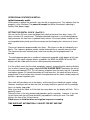
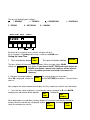
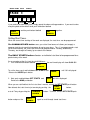
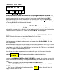
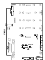
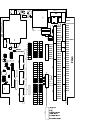
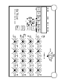
ELECTRONIC & TECHNICAL SERVICES Ltd
INSTALLATION AND USER MANUAL
E&TS IRRIGATION CONTROLLERS
Thank you for purchasing an ETS Irrigation controller
If treated in accordance with the following instructions it should give a long and trouble free
service.
OPERATIONAL FEATURES
1) The digital clock has large bright red digits and is easy to read.
2) 8 programmable starts per day, seven days per week; a total of up to 56 starts per
week.
3) Those starts can be set for each day from 1 up to 8 in any sequence, or for a week at a
time with “day omission.”
4) It is recommended that no more than 2 valves be connected per station in serial
configuration and one valve connected per station in parallel configuration. Each valve is
individually time in the parallel configuration.
5) Valve base times from 10s of minutes to 1 second, or to 0.2 seconds for misting.
6) Various types of rainfall sensor can be attached and used to over-ride or integrate
external irrigation.
7) Continual cycling is available for misting. No difficult programming is required. Simply
connect the Mist controller output into the terminal block labelled “Latched input.”
Weaning can be achieved by fitting an ETS Mist Wean controller.
8) An irrigation cycle can be initiated by an external start device which connects the
terminal blocks “labelled Mom latch.”
9) Watering by ‘hand’ when a solenoid valve is connected to the ‘Hand watering’ terminal
block and to the Common terminal.
Pump can be selected from the front panel to run or to be turned off
Feed Valve, if available can also be selected.
10) When the panel is running the pump can be turned on or off from the front panel by
pushing the tactile switch labelled ‘pump’. The pump ‘state’ will be stored in memory and
applied the next time that the panel runs
11) Error checking systems continuously monitor the condition of the rotary switches and
look for open or shorted solenoid valve circuits. A built-in sounder, Status LED and station
indicator give warning of any error condition, pulsing at a rate specific for the error
condition.
12) The duration of all irrigation times can be altered manually by the “Percentage +
control” between -90% and +100%.
13) Evaporation or humidity sensors with an output of 0-5Vdc or 0-20mA dc are sampled,
integrated and averaged. The algorithm calculates the adjusted irrigation time per station
from the output of the sensor.
14)Stations are ‘skipped’ if set above zero with no valve attached. The error checking
system will warn of an open circuit valve at the end of the irrigation cycle.
15) The Feed valve can be programmed to any station in serial and to banks of four in
parallel.
16) Single station serial operation or single parallel bank operation.
MOUNTING AND WIRING UP THE CONTROLLER
REFER TO FIG.3
Remove the four screws holding the front panel to the rear enclosure.
WITH GREAT CARE remove the three flat ribbon cables from their respective sockets.
Please note these are ‘keyed’ and can only be inserted one way. Refit the cables when
wiring complete.
The controller should be mounted on a flat surface and secured by bolts screwed through
the holes provided in each corner of the box. Do not make other holes in the box for this
purpose.
The ETS controllers should be wired in accordance with FIG.3.
IMPORTANT
Ensure that the mains supply is disconnected before wiring the controller.
Ensure that the mains supply is clean, and that there are no inductive loads such as large
pumps or motors on the same supply. It is recommended that the controller be wired
directly to the main distribution board.
We recommend that you protect the controller with an RCD rated at 2 Amps.
Connect:The 240Vac live (brown) wire to the fused terminal block labelled L,
The neutral (blue) to the terminal block labelled N,
The earth (green and yellow) to the terminal block labelled E.
Ensure that the Earth terminal runs to a bonded metal pipe or to a dedicated earth rod,
and that the impedance to earth is <5 Ohms.
CONNECTING SOLENOID VALVES
Connect the solenoid valve 1 to terminal 1, solenoid valve 2 to terminal 2, and so on for
the remaining valves.
Connect the other wire from each of the solenoids to a common return. The terminal
blocks for this are labelled COMM.
In the U K it is a statutory requirement that you keep all the low voltage cables clear of the
240vac high voltage supply, in accordance with the Low Voltage Directive. Please take
care to do this!
CONNECTING THE PUMP
The pump cannot be driven directly from the controller. Use an appropriate relay with a
24Vac coil, and connect the relay coil across terminals PUMP and COMM.
MORE EXTERNAL INPUTS AND OUTPUTS
CONNECTING THE FEED VALVE
Connect the solenoid valve across the terminal block labelled FEED and the return to
COMM
REMOTE STOP, LOW RESERVOIR CUT OUT
A closed contact across the terminals labelled Lo res/0V, Lo res will suspend the
program. The alarm led will flash and the sounder will beep on/off until the low reservoir
fault condition is removed. The program will continue from point of suspension.
If a float switch is fitted in the water reservoir and connected to the Lo res contacts, the
program will be suspended when the water level in the reservoir drops below the float
switch, causing contact closure. The program will remain suspended until the water level
increases above the float switch and opens the contacts.
REMOTE STARTS
There are two kinds of remote starts: momentary and cycling/latched.
1. A momentary start device, such as a closed contact or the output from an Evaporimeter
wired across terminals labelled MOMENTARY and common arrow point will start an
irrigation program once. The clock display will thereupon read PS1 for no more than four
seconds. PS1 indicates that the start has been form an external source
2. A latched or cycling start can be initiated by a suitable device wired across terminals
labelled LATCH and common arrow point. The controller will operate the program for as
long as these contacts are closed and can be used for misting, multiple cycling and for
pulsed irrigation programs.The display will constantly read PS1.
HAND WATERING
A permanent 24v AC supply is available across HANDWATER and COMM. When this
supply is healthy the LED labelled ValveSupply OK is illuminated.
Hand watering can be accomplished in two ways:
i) pump, selected by pushing the Pump Control push button.
ii) pump and feed (where applicable) by selecting Feed Valve push button.
The pump and feed valve can be turned on/off by repeated pushes on their respective
buttons.
The feed valve will always turn off when the pump is turned off.
The manual start from the clock is inhibited when hand watering, the automatic start
sequence from the clock is not affected.
SETTING THE GRASLIN CLOCK
Clock has been pre wired, please refer to the manufacturers instructions for
clock setting.
NOTE. When the clock slide switch is in the ‘ON’ up position, external starts
i.e. momentary starts and latched starts are ignored.
When the switch is in the ‘AUTO’, middle, or ‘OFF’, down position, external
starts will be accepted.
The external latched start initiates a single cycle similar to the momentary
start.
OPERATIONAL FEATURES IN DETAIL:
Initial Automatic audit.
When power is applied the controller signs on with a signature tune. This indicates that the
program is fully functional. The power/int sample led will be illuminated, indicating a
healthy 5Vdc power supply
SETTING THE DIGITAL CLOCK (See FIG 1)
You can set the 24 hour seven day digital time clock to the local time; days, hours x10,
hours, minutes x10, and minutes. The battery-backed time base is crystal-controlled and
highly accurate; the local time is updated every minute. If the mains power should fail, the
re-chargeable battery back-up will ensure accurate time keeping for a minimum of seven
days.
There are 8 automatic programmable start times. Start times can be set individually or in
blocks. The sequence program can be started automatically or manually from the clock.
The clock can be reset manually and a new time and day can be programmed if so
desired.
The clock program operates a number of safeguards to provide a high degree of fail-safe
operation. If the clock software detects a problem, the MINS the MINSx10 and the DAY
displays will be visible while the error is being corrected automatically.
If in the unlikely event that the clock completely ‘freezes’ and pushing the clock set buttons
has no effect, remove the jumper labelled CLOCK SUICIDE RESET located on the rear of
the main control board FIG.2. This will remove all power from the clock, wait for 2 seconds
and replace jumper. All stored information will have been lost, the clock will have to be re
programmed. A reset action after removal and replacement of the clock suicide jumper will
prevent a spurious irrigation cycle.
Your clock will have been set at the factory, and the local time should not require setting.
However should you wish to alter the time, or simply familiarise yourself with the workings,
here is a step by step guide:
Note: if you reset the clock, or if the clock has never been set, the display will flash. This is
perfectly normal.
Setting the time is the only complicated procedure on this controller. However, if you can
set an alarm clock you will have absolutely no problem in setting this one. The clock
displays the time in the 24 hour format.
Clock access is inhibited when an irrigation sequence is running.
TIME DOES NOT AUTOMATICALLY ADJUST FOR BST AND GMT
The days will be displayed as follows:
= MONDAY
t = TUESDAY
F = FRIDAY
S = SATURDAY
HOURS MINS
DAYS
= WEDNESDAY
t. =THURSDAY
S. = SUNDAY
STARTS
12:00
H OU R S
S TAR T
MI N S
SET
T IM E
SET
S TA R T S
C OM M ON
S TA R T S
SET DAY
D A IL Y
S TA R TS
RESET
By default for a new clock, hours, minutes and days will flash
As an example it is Tuesday and the time is to be set to 15:30 hours.
Setting the Local Time.
SET
TIME
1. Push and hold the button labelled
Then push the button labelled
HOURS
The hours display will increment (count upwards). When the clock shows 15:00
release the HOURS
push button. If you release the SET TIME push button before the
HOURS push button a manual start sequence will be initiated.
If this is a problem push the reset button to terminate the
Sequence
2. Now push the button labelled
When 30 is displayed, release the
now set.
MINS
The minutes display will increment.
and the SET TIME push buttons. The local time is
Next, program the action window which displays the Day, stored starts and the start information.
1. To set the day, which by default is set to Monday (always displayed as Π in the DAYS
window) push and hold the button labelled
followed by
SET
SET
STARTS
TIME
When both buttons are held down, the days display will increment from Monday through to
Sunday. When the correct day is displayed, release
followed by.
SET
SET
Local time and date are now set.
START
TIME
HOURS MINS
DAYS
15:30
t
H OU R S
M IN S
S TAR T
SET
T IM E
STARTS
SET
S TA R T S
C OM M ON
S TA R T S
SET DAY
D A IL Y
S TA R TS
RESET
If you make a mistake at any time, simply repeat the above setting procedure. If you want to clear
everything back to the default level push the button labelled
DAILY
STARTS
and the push button labelled
SET
STARTS
together.
Setting Start Times.
When the correct time and day of the week are displayed, the start times can be programmed.
The COMMON STARTS button saves you a lot of time because it allows you to apply a
common start time to a particular program for up to seven days. Thus, if you programmed a start
for 06:30 on Monday, the same start time can be programmed for Tuesday, Wednesday,
Thursday, etc through to Sunday, by one touch of the button.
The DAILY STARTS button allocates an individual start time to be programmed for a
particular day of the week.
As an example set the first start time to 06:30 hours
1. Push and hold the button labelled
the real time display will show 00:00. tS1.
SET
STARTS
To set the hours push and hold down SET STARTS and
Release the HOURS push button.
2. Next, push and hold down SET STARTS and
Release the MINS pushbutton
HOURS
MINS
until 06 is displayed.
until 30 is displayed.
When you are satisfied that the first start time is correct, release the SET STARTS push button.
Now allocate that start time to just one day by pushing the
or to all 7 days by pushing the
button and press the
COMMON
STARTS
DAILY
STARTS
DAILY
START
button,
button. To check, release SET STARTS push
again to scroll through stored start times
HOURS MINS
DAYS
STARTS
06:30 t S 1
H OU R S
MI N S
S TAR T
SET
T IM E
SET
S TA R T S
SET DAY
C OM M ON
S TA R T S
D A IL Y
S TA R TS
RESET
The action window should now show the following information: 06:30 tS1 This
shows the first start time has been programmed for 06:30 on Tuesday. You can either program the
remaining seven starts in the manner described or leave them unused. Keeping the DAILY
STARTS pushbutton pressed will scroll through the remaining seven starts all should display
00:00, through to Wednesday which should show the first start time as 06:30 S1, scroll through
to Thursday, 06:30 t.S1 etc for the rest of the week.
The second start time will now be displayed as
06:30 t S2. this shows that the previous start
time has been set has been set at 06:30 and the clock is now waiting for the 2nd start time,
pushing either common starts or the daily start will be ignored until a new start time is entered that
is different to the first start time, e.g. a new start time of 06:31 will be accepted
Note that only one start time will be selected by pushing either COMMON STARTS or DAILY
START, Otherwise the same start would be allocated to all start times.
All unused starts should be set at 00:00, which is ignored as a start time. If you want to start an
irrigation sequence at midnight, set the nearest start time to either 23:59 or 00:01. All other
times are permitted.
You can program as many starts as you like up to the maximum permitted of eight starts. It is not
the sequence of starts that determine the irrigation cycles but the times programmed. For instance
if you program start eight with a time of 06:00 hours and start one with 07:00 hours, start eight will
run the first irrigation cycle followed by start one.
Once all starts have been programmed, to see and confirm your start times push the button
labelled
DAILY
STARTS
this will sequence through days and related start times.
A mixture of COMMON STARTS and DAILY STARTS is allowed. For instance you may wish
to have common starts for Monday, Tuesday and Wednesday but different starts for the remaining
4 days.
1. Sequence through to the day by pushing the DAILY STARTS button,
2. Push the SET STARTS button, select the start time and accept by pushing the DAILY
STARTS push button.
SET
3. When you are satisfied with all start times push the
button, which will return the
TIME
display to the local time and day.
SETTING THE IRRIGATION CYCLE
Setting the irrigation cycle is very simple.
1) Set the time base required by turning the TIME BASE rotary switch to the desired time
base:- 0.2SECS, SECS, SECS X 10 , MINS, or MINS X 10.
2) Set the station multiplier to the desired setting from 0 to 9. When a particular knob is
set to zero, that valve will not be operated, and the controller moves through to the next
set station.
For example, if the TIME BASE is set to SECS and STN 1 is set to 3 Valve 1 will be
on for 3 seconds.
3) Set all remaining stations in the same manner.
SEQUENTIAL OPERATION
This mode is normally used on smaller controllers. To run it, remove the jumper from the
terminals labelled PARALLEL (located on the lower left centre of the rear board, as shown
in fig2).
When the program runs, the LED for station 1 will be illuminated and voltage will be
supplied to valve 1, which should open! At the end of the time set, LED 1 will extinguish
and valve 1 will close. The program will sequence to station 2, the LED for which will be
illuminated, and valve 2 should open. This process is repeated for each station in turn.
PARALLEL OPERATION
This mode is particularly useful for larger controllers. To run it, fit the jumper to the
terminals labelled PARALLEL, as above. Four stations will operate at the same time,
each for the length of time set when it was programmed.
When a program starts, the LED’s for stations 1, 2, 3 and 4 will be illuminated and the
respective 4 valves will open. As the stations time out the respective station indicator and
valve will close. If all the stations are set to the same time all valves and station indicators
will open and close together.
With the 16 station controller bank 1 stations 1 to 4 come on first followed by bank 2
stations 5 to 8, bank 3 stations 9 to 12 and finally bank 4 stations 13 to 16. 24 through to
48 stations operate in the same manner
PROGRAMMING FOR FEED.
The software allows the FEED VALVE to be programmed for every station. The FEED can be
programmed on or off. When the panel is in a quiescent state pushing the ADVANCE button will
illuminate station one and the FEED VALVE led indicators. If feed is to be applied on station one
push the ADVANCE button, FEED VALVE led will flash twice and the sounder will beep twice,
station two led indicator is now illuminated. If feed is not required on this station, push the FEED
VALVE push button, FEED VALVE led will flash once, then extinguish and the sounder will beep
once, push the ADVANCE button, station three indicator will be illuminated. Carry on programming
in this manner to the sixteenth station.
In parallel the feed valve is common to the bank of four stations.
Once programming is complete, push the ADVANCE button to check stored FEED VALVE data.
Stored FEED VALVE data is retained indefinitely in the event of a power failure.
Note that when the feed valve has been selected in a sequence, the FEED led flashes twice, the
sounder beeps twice. If feed has not been selected the FEED led does not flash and the sounder is
silent.
INITIATION OF AN IRRIGATION CYCLE
An irrigation cycle can be initiated in three ways:
1)By a timed automatic start.
2)By a manual start.
3)By a remote start.
A timed start from the digital clock has been explained in: SETTING THE DIGITAL
CLOCK.
When the clock initiates a start, the display will show both the real time and what it is
doing, displayed for example as FS1 (Friday start 1.) This will be displayed for up to 4
seconds (the clock interrupt routine). Then the action is cleared from the display, which
reverts to local time.
The manual start from the clock is inhibited when hand watering, the automatic start
sequence from the clock is not affected.
EXTERNAL STARTS
Any device which makes contact across the terminals labeled MOM LATCH or LATCH
can be used to start the irrigation program remotely. MOM is generally used for starting
irrigation programs, whilst LTH is generally used to start Misting or cycling programs.
PROGRAM ADVANCE
When the irrigation program is running, pushing the Program ADVANCE button will
advance the program to the next station. In parallel the next bank is selected.
ALTERING PROGRAM SETTINGS
These can be done whilst the program is running, simply by increasing or decreasing the
station time, or by selecting a new time base. If you want one station to stop operating,
simply set the knob to 0.
PUMP
The pump output is selected by pushing the PUMP CONTROL button when the program
runs. This state is always remembered even when the panel is turned off. This also applies
if the pump has been programmed off. The PUMP led indicator is lit when the pump is
running. This output can also be used to operate a master valve, a fertilizer injector or
similarly related equipment.
STATUS
When all is healthy the TIMER/PULSE led will flash at the time base rate, for instance if
the time base is set to 1 second the TIMER/PULSE led will flash at 1 second intervals.
SINGLE STATION (serial) SINGLE BANK (parallel)
Initiate an irrigation cycle. Push the ADVANCE to select the station or bank to be irrigated.
Push the FEED VALVE push button once, the sounder and Alarm led will bleep and flash
twice. The selected station/bank will irrigate once and when complete the irrigation cycle
will reset. This feature has to be selected every time an irrigation cycle is initiated.
Note. pushing the FEED VALVE during an irrigation cycle will reset the irrigation
cycle after the current station has finished watering.
DIAGNOSTICS (prevention of glass house flooding)
These are carried out automatically when the program is initiated. The program checks for
open circuit switches. At the end of the irrigation cycle the faulty switch is identified by the
station indicator. If station 3 switch is faulty, station 3 led and sounder will beep and flash
twice. This applies to all 16 stations. Once the fault condition has been rectified sounder
and led will turn off.
However even with a faulty switch, irrigation can safely continue. The software will identify
the faulty station and will apply a limited amount of irrigation. In serial this is 50% of the
time base, i.e. if switch 3 were faulty and the time base set to 10 secs, irrigation would be
applied for 5 seconds.
In parallel this is 10% or in the example above 1 second.
This process ensures that the glass house is not flooded but there is limited irrigation on
the faulty station.
Once the faulty switch has been identified rotate the switch vigorously to the left and right,
this switching action should clean the contacts. An application of WD40 may also help. To
do this , pull off cap and ‘squirt’ down the flat of the spindle. Wipe off excess oil.
FAULTY VALVE (on 16 stations and above)
To select this function, insert the 2 way jumper taped to the Output board (FIG.3)
into the header labelled VALVE SCAN and the 2 way jumper taped to the logic board
ito the header labelled VALVE TEST. If not required leave VALVE TEST header
empty. If not fitted the controller will skip the valve test routine.
In SERIAL - If a faulty valve is detected either open circuit or short circuit, the station and
valve are skipped and the next station is selected. At the end of the irrigation cycle the
faulty valve is identified by the station indicator. If the valve on station 3 is faulty, station 3
led and sounder will beep and flash three times. This applies to all 16/48 stations. Once
the fault condition has been rectified sounder and led will turn off.
Upon initiation of an irrigation cycle automatic error checking for all outputs occurs. In
serial this consists of a 120mSec sequential pulse to all outputs. Outputs whose stations
are set to zero are not checked.
In parallel, each output is checked as above in serial mode and then all outputs in a bank
of four are checked (all four led’s in the bank are on for 120mSec) for over current.
In serial mode short circuit or open circuit conditions give an error warning of 3 beeps and
3 alarm led flashes.
In PARALLEL where 1 or 3 stations are safely powering 3 valves with the 4th station open
circuit (no valve), the 4th station indicator will flash 3X and alarm sounder will beep 3X. If
one of the stations (1 to3) is short circuited (faulty valve) error warning will be 3 flashes
and 3 beeps (open circuit) followed by 4 flashes and 4 beeps (short circuit).
If all or one of the stations are left open circuit all station indicators will flash 3X and
3beeps followed by 4 flashes and 4 beeps. The valve detection circuit will provide a
common error for both short and open circuit.
PERCENTAGE ADDITION/SUBTRACTION
To select % addition/subtraction place jumper into MAN header on FIG.2
The operator can use a potentiometer labelled %, mounted on the front panel, to increase
or decrease all valve times between SCALE +100% and SCALE -90%. On hot days you
would increase the % control on dull overcast days you would decrease the % control.
When the control is set to “CALIBRATED” the irrigation time is the multiplication time
shown on the timer scale as described above. Thus
1. if the time on station one was set to 1 and the time base set to 10 SECS, the % control
set to CALIBRATED the irrigation time will be 10 secs.
2. If the % control were set to +100% the irrigation time would be 20 secs.
3. If the% control were set to -90% the irrigation time would be 1 second.
The % control will work on the 10 SECS, MINS and MINSX10 time bases, but it has no
effect on the 0.2 SECS and SECS time base.
Because of the integration software, if the percentage is adjusted prior to an irrigation
cycle the RESET button must be pushed, otherwise the percentage would be ‘averaged’.
This is explained in greater detail in the integration section.
INTEGRATION
To select integration place jumper into AUTO header on FIG.2 and disconnect the
lead from HDR2, if fitted
Simply put, this allows appropriate sensors to adjust the percentage addition/subtraction
control described above, automatically and in response to actual conditions..
A 0-5V dc signal is sampled every 5 minutes, indicated by a pulse of the POWER/INT
SAMPLE led. up to a maximum of 42 hours. The controller monitors a signal from an
evaporation device such as a Solarimeter an Evaposensor , Waterbug or a Delta T device
over a set period, usually the period between the controller start times. If all parameters
have been set up accurately such as the time base and multiplication factor on the station,
the algorithm converts the voltage input into an accurate frequency and automatically
calculates the exact amount of irrigation time to compensate for the evaporation period. If
sampling exceeds 42 hours, which in effect means that no irrigation has been applied for
this period, all information is cleared and the process repeats. The signal from the sensor
is sampled, digitised and stored every 5 minutes over a maximum period of 42 hours. If
during this period an irrigation cycle is initiated the sum of the digitised samples is divided
by the number of samples taken and the resulting average is used to adjust the watering
times.
Connect the output of your device to the terminals labelled INTEGRATOR and
LOWRES/0V terminals located on the output board, refer to FIG.3
Quick Start:
1) Connect controller to the valves, pump and mains supply( refer to the
relevant sections in the installation manual)
2) Set the time base
3) Set each station switch, remember the 0 – 9 positions on the switch x the
time base. If time base set to 10 SECS and the station switch to 3 the
irrigation time is 30 Secs
4) Push the reset button
5) Push the start button, refer FIG 1, digital clock will show PS1 for a max of 4
seconds.
6) Controller runs.
CONTROLLER CARE
Very low maintenance required.
At the end of season keep the mains power applied, this will prevent damp
entering and corroding metal parts.
To keep the rotary switch contacts clean turn fully to both end stops, DO
NOT USE FORCE.
DON’T use sharp or pointed objects to push the tactile switches, use fingers
only
Alarm Conditions
1) Low reservoir 1 beep, continuous, Lo Res led lit
2) Faulty switch 2 beeps, alarm led and station indicator flashes twice.
3) Serial, open circuit valve/short circuit valve 3 beeps, alarm led and station
indicator flashes 3X
4) Parallel Open or short circuit valve a combination of 3 and 4 beeps, 3 and
4 alarm led flashes.
ELECTRICAL SPECIFICATIONS.
Operates from a 240V ac mains supply.
Integral 600mA mains suppression filter.
F2 Mains fused input rated at 500mA slow blow 5 x 20mm
24V ac output for valves and pump relay F4 rated at 1.5A quick blow 5x20mm
Low voltage processor supply F3 rated at 1A quick blow 1 amp 5x20mm
30VA, 24v ac secondary toroidal transformer, maximum output 1Amp
Valve common is bonded to Earth
Rechargeable clock battery
Plastic double insulated enclosure, size 240mm x 190mm x 90mm
Declaration of Conformity
Name of manufacturer
Full postal address
Country of origin
E&TS Ltd
40 Acreville Rd
Bebington
Wirral
Cheshire CH63 2HY
UK
Description of product
Irrigation Controller
Conforms to the requirement of the EMC directive 89/336/EEC, of low voltage directive
73/23/EEC and harmonised European and national standards.
Applied standards:
EN50081-1 EMC generic emission
EN50082-2 EMC generic immunity
We declare that as the authorised representatives, the above information in relation to the
manufacture of this product is in conformity with the stated standards and other related
documents following the provision of EEC directives.
CLOCK SUICIDE RESET
PARALLEL
SERIAL
VALVE TEST
MAN
AUTO
FIG.2
HDR2
TB15
INTEGRATOR
LOW RES/0v
LOW RES
MOM LATCH
LATCH
STATIONS
STN56
28
TR55
TR27
TR56
TR28
TR26
TR25
TR54
TR53
TB7
TR51
TR23
TR52
TR24
R9
TR50
TR22
R6
TR49
TR21
C13
TR20
R2
TR48
TR47
R22
R7
TR46
HDR5
HDR3
TB10
C14
TR18
TR17
TR45
C12
TB6
TR44
TR43
R1
R19
R21
R20
S1
TB4
R5
TR15
TR14
R39
TR42
TR41
HDR9
TB9
TR12
TR11
TR40
D3
R26
R25
TR39
HDR7
R28
R4
TR10
TR38
TR37
R24
R23
R29
C17
TB5
STN64
TR64
STN63
TR8
TR63
TR35
R30
R36
R34
TR62
R35
T1
TR34
TB11
TR33
R27
R33
R3
TR7
R31
R32
TR36
STN62
TB14
TR4
C19
FIG.3
TR9
HDR4
STN44
STN16
T2
STN52
STN24
STN43
STN15
TR13
D1
STN51
STN23
INTEGRATOR
STN42
STN14
REL1
STN50
STN22
TR19
LOW RES/0v
STN41
STN13
TR60
R38
TR32
TR59
TB8
TR31
TB3
TR58
HDR10
TR30
TR57
TR29
Tr65
TRF2
TB1
COMM
COMM
T3
STN49
STN21
TB12
STN55
27
STN48
STN20
LOW RES
MOM LATCH
LATCH
STN40
STN12
STN36
STN8
COMM
COMM
R8
STN54
26
STN47
STN19
TR16
STN45
STN39
STN11
STN35
STN7
COMM
COMM
VALVE SCAN
HDR2
TR61
TR5
STN59
TR3
TR2
TR1
COMM
COMM
D7
D10
U1
STN37
STN34
STN6
STN61
TR6
STN60
STN32
STN31
STN3
STN58
STN57
STN29
FEED
PUMP
COMM
COMM
COMM
HDR6
STN53
25
STN46
STN18
STN17
STN38
STN10
STN9
STN33
STN5
STN4
STN30
STN2
STN1
HAND WATER
COMM
COMM
R18
PUMPTRIAC
HDR1
R17
2 Amps
F4
1 Amp
F3
LED3
D2
Filter1
FILED 02. 03. 2003.
JOHN WALKER 02. 03. 2009.
4-64 NON ISOLATED IRRIGATION OUTPUT
TB13
C
COMM
VALVE SUPPLY OK
EARTH
C5
C4
TRF1
C1
NEUTRAL
VReG
C2
TB2
LIVE
BR2
F2
C3
500mA
HOURS
HOURS
START
MINS
MINS
SET
TIME
-25
+100
STARTS
RESET
RESET
PUMP
CONTROL
FEED
VALVE
ADVANCE
+75
+50
+25
COMMON DAILY
STARTS
STARTS
DAYS
SET
STARTS
%
++
CALIBRATED
SET DAY
-50
-75
-90
E&TS Ltd
For all your irrigation needs
3
4
5
5
TIME BASE
4
5
SECS
X10
SECS MINS
MINS
X10
200mS
4
4
5
STN
4
7
6
2
6 STN 3
3
7
8
6 STN
9
7
0
2
5
8
9
4
1
5
8
4
1
0
6 STN 3
2
7
9
2
6 STN 3
1
0
7
5
2
9
4
1
5
8
4
1
0
3
2
6 STN 3
7
7
9
2
6 STN 3
6
0
7
9
2
6 STN 3
5
0
7
9
2
0
8
5
1
4
8
5
1
4
8
5
1
9
4
8
5
STN
12
7
6
2
3
7
6 STN 3
11
2
6 STN 3
10
7
9
2
7
6
7
8
9
1
0
8
6 STN 3
15
0
2
6 STN 3
9
2
9
7
0
2
9
8
0
1
5
8
4
1
5
8
4
1
5
8
9
4
7
9
STN
16
1
5
2
1
0
6 STN 3
14
7
6 STN 3
13
2
8
9
1
0
8
9
1
3
0
4
1
0
4
8
FEED
VALVE
ALARM
LOW
RES
POWER/
INT
SAMPLE
TIMER
PULSE
PUMP
0