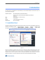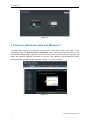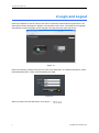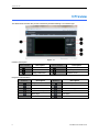
1
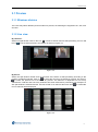
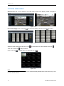
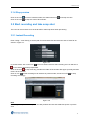
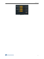
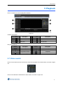
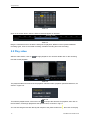
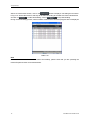
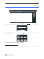
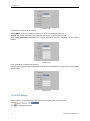
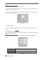
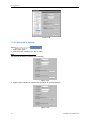
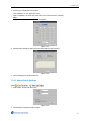
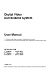
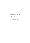
Web Client Guide TVR Digital Video Recorder Version 2.20 8200-2656-05 C0 Notice The information in this manual was current when published. The manufacturer reserves the right to revise and improve its products. All specifications are therefore subject to change without notice. Copyright Under copyright laws, the contents of this manual may not be copied, photocopied, reproduced, translated or reduced to any electronic medium or machine-readable form, in whole or in part, without prior written consent of Tyco International Ltd. ©2010 and its Respective Companies. All Rights Reserved. American Dynamics 6600 Congress Avenue Boca Raton, FL 33487 U.S.A. Customer Service Thank you for using American Dynamics products. We support our products through an extensive worldwide network of dealers. The dealer through whom you originally purchased this product is your point of contact if you need service or support. Our dealers are empowered to provide the very best in customer service and support. Trademarks The trademarks, logos, and service marks displayed on this document are registered in the United States [or other countries]. Any misuse of the trademarks is strictly prohibited and Tyco International Ltd. will aggressively enforce its intellectual property rights to the fullest extent of the law, including pursuit of criminal prosecution wherever necessary. All trademarks not owned by Tyco International Ltd. are the property of their respective owners, and are used with permission or allowed under applicable laws. Product offerings and specifications are subject to change without notice. Actual products may vary from photos. Not all products include all features. Availability varies by region; contact your sales representative. License Information Read this license agreement before opening the disk package, downloading the software, installing the software, or using your system. This license agreement defines your rights and obligations. By breaking the seal on this package, installing the software, or using your system, you agree to all of the terms and conditions of this agreement. If you do not agree to all of the terms and conditions of this agreement, you may, within 30 days, return this package, all the documentation, and all accompanying material(s) to the point of purchase for a refund. Software License The Software includes the computer code, programs, and files, the associated media, hardware or software keys, any printed material, and any electronic documentation. The Software may be provided to you pre-installed on a storage device (the media) as part of a system. The Software is licensed, not sold. i Grant of License This agreement between Sensormatic Electronics Corporation (Sensormatic) and you permits you to use the Software you purchased. Once you have purchased the number of copies you require, you may use the Software and accompanying material provided you install and use no more than the licensed number of copies at one time. The Software is only licensed for use with specified Sensormatic supplied equipment. If the Software is protected by a software or hardware key or other device, the Software may be used on any computer where the key is installed. If the key locks the Software to a particular System, the Software may only be used on that System. Other Rights and Limitations A demonstration copy of the Software is considered purchased and is covered by this license agreement . You may not de-compile, disassemble, reverse engineer, copy, transfer, modify, or otherwise use the Software except as stated in this agreement. The hardware/software key, where applicable, is your proof of license to exercise the rights granted herein and must be retained by you. Lost or stolen keys will not be replaced . If the Software is provided as part of a System, the Software may only be used with the System. You may not sub-license, rent or lease the Software, but you may permanently transfer the Software to another party by delivering the original disk and material comprising the Software package as well as this license agreement to the other party. Initial use of the Software and accompanying material by the new user transfers the license to the new user and constitutes the new user's acceptance of its terms and conditions. The Software is not fault tolerant and may contain errors. You agree that the Software will not be used in an environment or application in which a malfunction of the Software would result in foreseeable risk of injury or death to the operator of the Software, or to others. Sensormatic reserves the right to revoke this agreement if you fail to comply with the terms and conditions of this agreement. In such an event, you must destroy all copies of the Software, and all of its component parts (e.g., documentation, hardware box, software key). The Software may contain software from third parties that is licensed under a separate End User License Agreement (EULA). Read and retain any license documentation that may be included with the Software. Compliance with the terms of any third party EULA is required as a condition of this agreement. The Software may require registration with Sensormatic prior to use. If you do not register the Software this agreement is automatically terminated and you may not use the Software. Upgrades and Updates Software Upgrades and Updates may only be used to replace all or part of the original Software. Software Upgrades and Updates do not increase the number copies licensed to you. If the Software is an upgrade of a component of a package of Software programs that you licensed as a single product, the Software may be used and transferred only as part of that single product package and may not be separated for use on more than one computer. Software Upgrades and Updates downloaded free of charge via a Sensormatic authorized World Wide Web or FTP site may be used to upgrade multiple systems provided that you are licensed to use the original Software on those systems. ii TVR Web Client Guide V2.20 Tools and Utilities Software distributed via Sensormatic authorized World Wide Web or FTP site as a tool or utility may be copied and installed without limitation provided that the Software is not distributed or sold and the Software is only used for the intended purpose of the tool or utility and in conjunction with Sensormatic products. All other terms and conditions of this agreement continue to apply. Failure to comply with any of these restrictions will result in automatic termination of this license and will make available to Sensormatic other legal remedies . Copyright The Software is a proprietary product of Tyco International Ltd. and is protected by both the United States and International copyright laws. Limited Warranty Sensormatic warrants that the recording medium on which the Software is recorded, hardware key, and the documentation provided with it, will be free of defects in materials and workmanship under normal use for a period of ninety (90) days from the date of delivery to the first user. Sensormatic further warrants that for the same period, the software provided on the recording medium under this license will substantially perform as described in the user documentation provided with the product when used with the specified hardware. Customer Remedies Sensormatic's entire liability and your exclusive remedy under this warranty will be, at Sensormatic's option, to a) attempt to correct software errors with efforts we believe suitable to the problem, b) replace at no cost the recording medium, software or documentation with functional equivalents as applicable, or c) refund the license fee and terminate this agreement. Any replacement item will be warranted for the remainder of the original warranty period. No remedy is provided for failure of the Software if such failure is the result of accident, abuse, alteration or misapplication. Warranty service or assistance is provided at the original point of purchase. No Other Warranties The above warranty is in lieu of all other warranties, express or implied, including, but not limited to the implied warranties of merchantability and fitness for a particular purpose. No oral or written information or advice given by Sensormatic, its representatives, distributors or dealers shall create any other warranty, and you may not rely on such information or advice. No Liability for Consequential Damages In no event will Sensormatic be liable to you for damages, including any loss of profits, loss of data or other incidental or consequential damages arising out of your use of, or inability to use, the Software or its documentation. This limitation will apply even if Sensormatic or an authorized representative has been advised of the possibility of such damages. Further, Sensormatic does not warrant that the operation of the Software will be uninterrupted or error free. This limited warranty gives you specific legal rights. You may have other rights that vary from state to state. Some states do not allow the exclusion of incidental or consequential damages, or the limitation on how long an implied warranty lasts, so some of the above limitations may not apply to you. iii General If any provision of the agreement is found to be unlawful, void, or for any reason unenforceable, then that provision shall be severed from this agreement and shall not affect the validity and enforceability of the remaining provisions. This agreement is governed by the laws of the State of Florida. You should retain proof of the license fee paid, including model number, serial number and date of payment, and present such proof of payment when service or assistance covered by this warranty is requested. U.S. Government Restricted Rights The software and documentation are provided with RESTRICTED RIGHTS. Use, duplication, or disclosure by the Government is subject to restrictions as set forth in subparagraph (c)(1)(ii) of the Rights in Technical Data and Computer Software clause at DFARS 252.227-7013 or subparagraph (c)(1) and (2) of the Commercial Computer Software-Restricted Rights at 48 CFR 52.227-19, as applicable. Manufacturer is Sensormatic Electronics Corporation, 6600 Congress Avenue, Boca Raton, FL, 33487. iv TVR Web Client Guide V2.20 Table of Contents 1 INTRODUCTION ............................................................................................................................................. 1 1.1 INSTALL W EB CLIENT ....................................................................................................................... 1 1.2 NOTES FOR W INDOWS VISTA AND W INDOWS 7.................................................................................. 2 1.2.1 Run web browser as administrator ......................................................................................... 3 1.2.2 Run web browser with administrator privileges always .......................................................... 4 2 LOGIN AND LOGOUT .................................................................................................................................... 6 3 PREVIEW .......................................................................................................................................................... 8 3.1 PREVIEW ......................................................................................................................................... 9 3.1.1 Windows division .................................................................................................................... 9 3.1.2 Live view ................................................................................................................................. 9 3.1.3 Live view control ................................................................................................................... 10 3.1.4 Stop preview ......................................................................................................................... 11 3.2 START RECORDING AND TAKE SNAP SHOT ....................................................................................... 11 3.2.1 Instant Recording ................................................................................................................. 11 3.2.2 Snap shot ............................................................................................................................. 12 3.3 VOICE TALK ................................................................................................................................... 12 3.4 IMAGE PARAMETERS ...................................................................................................................... 12 4 PTZ ................................................................................................................................................................... 14 5 PLAYBACK ..................................................................................................................................................... 15 5.1 VIDEO SEARCH .............................................................................................................................. 15 5.2 PLAY VIDEO ................................................................................................................................... 16 5.3 SCREENSHOT AND DOWNLOAD ....................................................................................................... 17 6 LOG .................................................................................................................................................................. 19 7 CONFIGURE ................................................................................................................................................... 20 7.1 LOCAL CONFIGURATION .................................................................................................................. 20 7.2 EXPORT AND IMPORT CONFIGURATION FILE OF TVR ........................................................................ 21 7.3 REMOTE CONFIGURATION .............................................................................................................. 22 7.3.1 Device Parameters ............................................................................................................... 22 7.3.2 Channel Parameters............................................................................................................. 23 7.3.3 Network Parameters ............................................................................................................. 31 7.3.4 Serial Parameters ................................................................................................................. 36 7.3.5 Alarm Parameters................................................................................................................. 37 7.3.6 Exception Parameters .......................................................................................................... 40 7.3.7 Account Management........................................................................................................... 40 7.3.8 Hard drive Settings ............................................................................................................... 42 7.3.9 Update Remotely .................................................................................................................. 42 7.3.10 DST Settings ...................................................................................................................... 42 1 Introduction (I) 1 Introduction The Web Client is embedded in the TVR. When you use the web browser to access the TVR, it is downloaded automatically. Operation System: Microsoft Windows XP with SP2 and SP3, Windows Vista 32 bit Home/Premium/Ultimate with SP2 and Windows 7 CPU: Intel Pentium IV 2.4 GHz or above RAM: 1G or above Display: 1024×768 resolution or above Web browser: IE 6, IE 7 and IE8. 1.1 Install Web Client Change the internet security level to ensure that the ActiveX control can be downloaded. Open the IE browser and navigate to: Tools (see Figure 1-1). In the Settings list, enable all options related to the ActiveX control. Figure 1-1 Enter the IP address or domain name of the TVR in the Browser address field and press Enter, then please confirm the installation of web client for first use. The language option includes English, French, Simplified Chinese, German, Spanish, Italian and Portuguese (Brazilian). After installation, an interface appears (see Figure 1-2), which indicates the web client has been downloaded successfully. 1 1 Introduction (I) Figure 1-2 1.2 Notes for Windows Vista and Windows 7 The Web Client requires write permission if users want to save screen shots, video clips or TVR configuration files. For Windows Vista and Windows 7 user, please make sure you have the full administrator privilege before operation. Otherwise the UAC (User Account Control) of Windows will restrict the respective operation and cause it to fail, as in the examples preview snapshot, preview record and export configuration file, as shown in figure 1-3,1-4 and 1-5 below. Figure 1-3 2 TVR Web Client Guide V2.20 1 Introduction (I) Figure 1-4 Figure 1-5 1.2.1 Run web browser as administrator The user must operate the web browser with ‘Run as administrator’ method if taking a snapshot, recording video or exporting a configuration file. This will allow the Web Client to write files correctly. Right click on the browser icon and choose ‘Run as administrator’ option, as shown in figure 1-6 below. 3 1 Introduction (I) Figure 1-6 A user account control message box will popup, click on ‘Yes’ to proceed, as shown in figure 1-7 below. Figure 1-7 1.2.2 Run web browser with administrator privileges always In order to operate the web browser with default administrator privileges permanently, the properties of the web browser shortcut should be changed. Figure 1-8 4 TVR Web Client Guide V2.20 1 Introduction (I) Right click on the browser icon and choose ‘Properties’ option, as shown in figure 1-8 above. Figure 1-9 Select Shortcut tab, then click on ‘Advanced’ button, as shown in figure 1-9 above. Figure 1-10 In ‘Advanced Properties’ check box, click to enable the ‘Run as administrator’ option, then click on OK to proceed, as shown in figure 1-10 above. Figure 1-11 Click OK and a message box will popup, user must click ‘Continue’ to accept change, as shown in figure 1-11 above. Note If you do not understand the UAC of Windows Vista/7 or are not sure about your privileges, please contact your IT support organization for help. 5 2 Login and Logout (L) 2 Login and Logout Enter the IP address or domain name of the TVR in the browser address field and press Enter. The Web Client interface will appear in English, and maximize to full screen. It will adapt to OS language automatically, and the language can be changed in the drop down list at the right corner. Figure 2-1 Enter the username, password and port to access to the Web Client. The default Username is admin, the default Password is 12345, and the default port is 8000. Figure 2-2 When you want to exit the Web Client, click Logout 6 TVR Web Client Guide V2.20 2 Login and Logout (L) Figure 2-3 7 3 Preview (P) 3 Preview The Web Client will enter the preview interface by default following a successful login: Figure 3-1 Interface description: Zone number Description Zone number Description Device and channel Video panes PTZ Light, Wiper and PTZ Menu Image parameters Playback control Table 3-1 Playback control buttons: Buttons Description Buttons Description Single camera 4 cameras split 9 cameras split 16 cameras split Snap shot All channels stop preview All channels stop record All channels start record Next page Last page Audio On/Off Table 3-2 8 TVR Web Client Guide V2.20 3 Preview (P) 3.1 Preview 3.1.1 Windows division The users may select different preview modes for preview; the following are supported 1X1, 2X2, 3X3 and 4X4. 3.1.2 Live view By channels: Select one split window. Click on the icon in front of channel name to start previewing, the icon will turn to if the channel preview is successful as shown in Figure 3-2. Figure 3-2 By device: Select one split window. Double click on the name of the device to start previewing according to the number of windows selected. Click on to select the next set of channels for preview, and click on to select the previous set of channels for preview. The behavior is dependent on how many channels the TVR has and how many windows have been selected for previewing. For example if a 2X2 split window is selected and the TVR has a total of 16 channels then each time is clicked the next 4 channels will be displayed. Figure 3-3 9 3 Preview (P) 3.1.3 Live view control Zoom: Double click on one channel in live view mode to full screen display, double click again to restore. Figure 3-4 Full screen display: click on the icon for full screen display, click on the icon to restore. Figure 3-5 Select live view channel and click on the icon Then click on the icon Click on the icon to enable audio, the audio status will turn to . to adjust volume. to disable audio, the status will turn to . Figure 3-6 Note Only one audio channel can be enabled, so it will automatically disable last channel’s audio if you turn on next channel’s audio. 10 TVR Web Client Guide V2.20 3 Preview (P) 3.1.4 Stop preview Click on the icon in front of camera number, the status will turn to Click on the icon to stop live view of all channels. and stop live view. 3.2 Start recording and take snap shot The user can record video on to the local HDD or take snap shots when previewing. 3.2.1 Instant Recording Enter Config > Local Config, to set the path for saved video files and select the size of video file as shown in Figure 3-7. Figure 3-7 In preview mode, click on the icon in front of camera name to start recording, the icon will turn to if successful, otherwise prompt failed. Click on the icon to stop recording, and then the folder of saved video files pops up briefly and then returns to the task bar. Click on icon to start recording for all channels in preview mode, and click on icon recording accordingly. to stop Figure 3-8 Note Recording will stop automatically when the disk partition has less than 500M free space or quit live view. 11 3 Preview (P) 3.2.2 Snap shot Enter Config > Local Config, set the save path for preview image files, as shown in Figure 3-9. Figure 3-9 In preview mode, click on icon up. to take snap shot, and then the folder of saved image files will pop Note Snap shot will fail when the partition has less than 500M free space. 3.3 Voice talk In preview mode, click on the icon as shown in Figure 3-10. to start voice talk with the TVR, click icon to stop voice talk, Figure 3-10 3.4 Image parameters Select a camera in preview mode, and then Brightness, Contrast, Saturation and Hue can be adjusted as shown in Figure 3-11. Click on level. Click on 12 to increase level, click on to decrease level, or click on or to set appropriate to restore default settings. TVR Web Client Guide V2.20 3 Preview (P) Figure 3-11 13 4 PTZ (P) 4 PTZ In the preview interface, the user can operate PTZ control. Before PTZ operations, please make sure that RS-485 parameters has been correctly configured and the PTZ camera or Speed Dome have been connected. Please refer to chapter 7.3.4 Serial Parameters for PTZ RS485 configuration. (Please note that when using a PTZ dome such as the AD Ultra 8 for example, which uses the AD422 PTZ protocol 4800 baud, it is necessary to reboot or power up the camera after the PTZ settings have been entered in the TVR PTZ menu. During the power up operation the camera will detect the type of PTZ network it is connected to. An on screen message over the camera’s video will display “detecting network”. During this time the user should click on one of the direction arrows shown in Figure 9-3 below. After about 30 seconds the network will be detected and display “EIA422”. Continue to click on one of the direction arrows for a further 15 seconds and the camera should respond to the PTZ commands being sent.) There are 8 keys to control PTZ directions, click the icon to start and stop auto scan. The function of this button when used with an AD Ultra 8 camera or Optima LT camera is to initiate the “apple peel” pattern. Clicking the icon again stops the “apple peel” pattern. Click the function keys on the right to adjust focus, iris and zoom. Click the icon to turn on light, click the icon applicable for all cameras) Click the icon to start wiper. (This operation may not be to access to PTZ menu. Click buttons to move upward and downward in the dome camera’s menu. Focus out button acts as the enter button in camera dome menu. If a preset has been configured correctly, user can select the preset from dropdown list and click to call it. Figure 4-1 Note The user can control PTZ in preview mode only. The PTZ Menu function is only available for cameras that contain an inbuilt PTZ domes menu. If a dome has no PTZ menu, there will be no response when clicking this button. 14 TVR Web Client Guide V2.20 5 Playback (P) 5 Playback Click on Playback to enter the playback interface. Figure 5-1 Interface description: Area Description Area Description Channel area Playback window Play control buttons Playback status Query area Time axis area Table 5-1 Play control buttons: Button Description Button Description Play Stop Slow forward Fast forward Single frame forward Snap shot Save clip Enable/Disable sound Table 5-2 5.1 Video search Click on the channel name and choose the camera for playback from channel area, as shown in figure 5-2. Figure 5-2 Click on the calendar to select date for video search, as shown in figure 5-3. 15 4 Playback (P) Table 5-3 Click on the search button, then the Search result will appear on time bar. Table 5-4 Drag the camera time bar to locate the start point for playback, different colors represent different recording types, such as command recording, schedule recording and event recording. 5.2 Play video After the video search, click on time bar to start playback. to begin playback. You can also double click on the recording Table 5-5 The playback status zone will show the playback channel number, playback speed and start time, as shown in Figure 5-6. Table 5-6 To locate the playback time, click on the icon and input the start time for playback, then click on the GO button, it will begin playback at the specified time, as shown in Fig 5-7. You can also drag the time bar directly with respect to the yellow marker line ‘ ’, then click on the play 16 TVR Web Client Guide V2.20 5 Playback (P) button to start playback from the yellow marker line time. Table 5-7 5.3 Screenshot and download Enter Config > Local Config, set the save path for playback image files and download files. Table 5-8 In playback mode, click on the icon pop up. to take snap shot, and then the folder of saved image files will In playback mode, click on the icon to save video clip, then the “save as” dialog box will pop up as shown in Fig 5-9, input file name and click on the Save button to start downloading, Click on the icon to stop downloading. Table 5-9 Note The Snap shot will fail when the drive has less than 500M free space. 17 4 Playback (P) After a successful video search, click on the button to display a new dialog box as shown in Fig 5-10. All the video files for that day will be listed according to the Start time. Select desired files and click on to start downloading, click on to stop downloading. During the downloading process, serial numbers of files and the download progress bar are displayed. Table 5-10 Note If the default download folder is not created successfully, please check that you are operating the Internet Explorer browser as an administrator. 18 TVR Web Client Guide V2.20 6 Log (L) 6 Log Click on Log to enter log search interface, as shown in Figure 6-1. Figure 6-1 Select log type and date as shown in Figure 6-2, and then click on to search matched logs. Figure 6-2 To search logs by a specified time range, you can tick as shown in Figure 6-3 and input time range for video search. Figure 6-3 Click on to export log with either Excel or Text format. Note You can search and display up to 2000 logs, please reduce the search time range or filter the Log Type if there are more than 2000 logs. 19 7 Configure (C) 7 Configure Click on Config to enter configure interface, there are two options - Local Config and Remote Config. 7.1 Local configuration Click on Local Config to enter local parameters settings, as shown in Figure 7-1. Figure 7-1 Local parameters description: Local Description Parameters Configure Protocol type File size Set network protocol, TCP and UDP are available. Set the file size for recording. Set stream type for network preview and Stream type available. Local parameters recording, main stream and sub stream are Network Transmission Set network transmission performance and Feature fluency. Path for saved video files Set the path for local recording. Path for preview images Set the path for preview snap shot. Path for playback images Set the path for playback snap shot. Path for download files Set the path for download recording. Table 7-1 20 TVR Web Client Guide V2.20 7 Configure (C) 7.2 Export and import configuration file of TVR Figure 7-2 Click on Export Configuration File, then a dialog box will be popped up as shown in Figure 7-3. Select save directory for configuration file, and then click on OK button. Figure 7-3 Click on Import Configuration File, then a dialog box displays as shown in Figure 7-4. Select configuration file and click on Open button. Figure 7-4 Note Export and import configuration file can be used for same model only. For example, configuration file of 21 7 Configure (C) one ADTVR04XXX unit can be applied to other ADTVR04XXX units only, and can not be applied to ADTVR08XXX or ADTVR16XXX. 7.3 Remote Configuration You can remotely configure the parameters of the device, including recording schedule, alarm schedule and etc. Click on Remote Config to enter remote parameters settings, as shown in Figure 7-5. Figure 7-5 7.3.1 Device Parameters In the Remote Setting menu, select the Device Parameters to set the TVR parameters. Figure 7-6 There are two parts to the Device Parameters: Device Information and Version Information. Device Information: Device name: 32 letters maximum, 16 characters maximum. 22 TVR Web Client Guide V2.20 7 Configure (C) Device ID: The largest ID number is 255. Record replace: To overwrite the record after the HDD is full, select [YES]. To stop the record after the HDD is full, select [NO]. Main BNC scale: Enable/disable video output scaling for main video output. Spot BNC scale: Enable/disable video output scaling for aux video output. Export player: To backup video with player, choose [YES]. To backup video without player, choose [NO]. The Channel number, HDD number, Alarm input number, Alarm output number, Device type and Serial number are not modifiable. Existing Video (days): This indicates how many days’ video has been recorded on hard drive. Version Information: Firmware version, Hardware version, Encode version and Front panel version are not modifiable. Click [Save]. Click [Reboot] if necessary. 7.3.2 Channel Parameters In the Remote Configuration menu, select the Channel configuration button to set the channel parameters. 7.3.2.1 Channel Display Settings Select You can configure channel name, OSD and related parameters here. Channel name: User-defined; 32 letters or 16 characters maximum. Setup OSD properties: Select whether to Display OSD, Display Position, Display Week, OSD Properties (Non Transparent&Flashing, Non Transparent&Non Flashing, Transparent&Flashing, Transparent&Non Flashing) and the OSD Type (date and time display format: MM-DD-YYYY). Setup the Channel Name properties: Select whether to display Channel Name (Display name) and the Display Position. Figure 7-7 23 7 Configure (C) 7.3.2.2 Encoding Parameters Configuration Select interface. to enter encoding parameters configuration Figure 7-8 Parameters Encoding Parameters Description Main/Sub stream and Event Parameters. Generally, Main stream is used for recording. Sub stream is used for network transmission. Stream Type Video&Audio or Video stream only. If [Video&Audio] is selected in the channel properties interface, then both video and audio can be recorded. Otherwise, select [Video] only. Resolution Recording Resolution. Default: 2CIF. Options: QCIF, 2CIF, DCIF and 4CIF. Only QCIF and CIF can be selected when the Type is Sub stream. Video Quality 6 options (only effective for variable bit rate type): Highest, Higher, High, Average, Low and Lowest. Bit Rate Type Variable & Constant Max Bit rate Maximum bit rate of the compressed stream Options: 32kbps, 48kbps, 64kbps, 80kbps, 96kbps, 128kbps, 160kbps, 192kbps, 224kbps, 256kbps, 320kbps, 384kbps, 448kbps, 512kbps, 640kbps, 768kbps, 896kbps, 1Mbps, 1.25Mbps, 1.5Mbps, 1.75Mbps, 2Mbps and Custom (user-defined). Frame Rate Record frame rate, from 1/16 to full frame Frame Type BBP & Single P frame I frame interval The interval between two I frames Table 7-2 24 TVR Web Client Guide V2.20 7 Configure (C) 7.3.2.3 Schedule Record 1. Select Enable recording by clicking the tick to enter configuration interface. . Figure 7-9 Parameters Description Redundant Redundant for this channel or not (When redundant disk is available) Days time Storage life of recorded files in redundant disk, expired data will be retention deleted Audio Record Recorded files include audio or not Pre Record Recording time options before alarm. Options: No PreRecord, 5s, 10s, 15s, 20s, 25s, 30s and Maximum. Post Record Recording time options after alarm stopped. Options: 5s, 10s, 30s, 1min, 2min, 5min and 10min. Schedule Record Event Record Normal Record schedule segment settings. Event Record schedule segment settings. Table 7-3 2. Click “Settings” of the “Schedule Record” to enter recording schedule configuration interface. Select “Weekday” as some day of the week or the whole week for recording time. The “All Day Record” or 8 “Segments” can be selected as well. Note The time of each segment can not be overlapped. 25 7 Configure (C) Figure 7-10 3. Click “Settings” of the “Event Record” to enter event recording schedule configuration interface. Select “Weekday” as some day of the week or the whole week for recording time. The “All Day Record” or 8 “Segments” can be selected as well. Click event type drop down list to select the recording type. Note The time of each segment can not be overlapped. Figure 7-11 7.3.2.4 Motion Detection Setting 1. Click to enter motion detection recording interface. 2. Select channel number for motion detection. Figure 7-12 3. Enable motion detection to activate “Area Settings”, “Arm Schedule” and “Linkage” settings. 26 TVR Web Client Guide V2.20 7 Configure (C) Figure 7-13 4. Set the motion detection area and sensitivity. The sensitivity 1 and 6 are the lowest and the highest level. Enable “Start Draw”, and select the detection area by using mouse. Figure 7-14 5. Set the detection time. “Arm Schedule” can be one day or the whole week, and 4 segments for one day. Figure 7-15 6. Set the “Trigger Recording” for linkage. 27 7 Configure (C) Click “Setting” in the linkage area and select “Alarm Trigger Mode” tab, choose relevant modes. Select “Trigger Recording” tab, choose relevant channels. Figure 7-16 7.3.2.5 Video Loss 1. Select the channel number for video loss. Click to enter Video Lost setting interface. 2. Enable “Video Lost” to activate settings of “Arm Schedule” and “Linkage” Figure 7-17 3. Set the Arm Schedule for video lost. Click “Settings” in “Arm Schedule” menu. Select “Weekday” as some day of the week or the whole week for the schedule. Note The time of each segment can not be overlapped. Figure 7-18 28 TVR Web Client Guide V2.20 7 Configure (C) 4. Set linkage for video loss. Click “Settings” in the “Linkage” menu. Note The Stop recording option is default ON, it will stop recording whenever video lost. Figure 7-19 7.3.2.6 Video Tampering 1. Select the channel number for video tampering. Select 2. Enable “Video Tampering Alarm” to activate settings of “Setting Areas”, “Arm Schedule” and “Linkage” Figure 7-20 3. Set the video tampering area and sensitivity. The sensitivity can be divided into three levels: Low, Medium, and High. Enable “Start Draw”, and select the detection area by using mouse. 29 7 Configure (C) Figure 7-21 4. Set Arm Schedule for video tampering. Click “Settings” in “Arm Schedule” menu. Select “Weekday” as some day of the week or the whole week for the schedule. 4 “Segments” can be selected. Note The time of each segment can not be overlapped. Figure 7-22 7.3.2.7 Video Mask 1. Select channel number, and enable video mask (i.e. Select ). Figure 7-23 30 TVR Web Client Guide V2.20 7 Configure (C) 2. Set the mask area. Click “Settings” to enter area set menu. Enable “Start Draw” (i.e. ), select the mask area by clicking and dragging the mouse. Figure 7-24 7.3.2.8 Text Overlay You can add characters on the screen of the channel. Select Tick “Strings 1” (i.e. ) to enable text overlay, double click the strings area to input the characters you want to overlay on the screen. It supports 6 lines maximum with 44 characters maximum per line. Figure 7-25 7.3.3 Network Parameters In the Remote setting menu, select the Network Parameters to set the network and relevant parameters. 31 7 Configure (C) Figure 7-26 7.3.3.1 Basic Configuration Select Configure the network according to the actual situation. If there is a DHCP server on the network, check the ‘Obtain Auto’ checkbox to enable DHCP service. Figure 7-27 Select “Advance” to enter advanced configuration. You can configure preferred DNS server1 and spare DNS server2, IP address of alarm host. Figure 7-28 32 TVR Web Client Guide V2.20 7 Configure (C) Parameters Description Device IP Address Device’s static IP address Device Port Device’s port, default is 8000 Subnet Mask Subnet mask Default Gateway If you go through a gateway to connect to the server, enter the gateway address MAC Not modifiable Multicast IP For multicast, enter a D-class IP. Range: 224.0.0.0 - 239.255.255.255 Http Port Applicable when using IE to connect to the server, default is 80 NIC Type The default is 10M/100M Auto DNS1 DNS2 Preferred and spare DNS server Alarm host Alarm signal can be uploaded to the IP address automatically Table 7-4 7.3.3.2 PPPoE Select Enable PPPoE by ticking , input the user name and password, then save the changes and reboot the device to make the parameters become effective. If succeed to dial, the current IP address will be displayed in the blank “DDNS IP”. Figure 7-29 7.3.3.3 DDNS Adopting DDNS function can solve the problems caused by dynamic IP. Click Enable DDNS. If the “IPServer” is selected as protocol, then input the address where the IP server is running. 33 7 Configure (C) Figure 7-30 If the “Dyndns” is selected as protocol: Server Name: Input the IP address of the server, such as members.dyndns.org; Domain: the domain name that user applied for the device, such as test.dynlia.com; User name, password and verify: the account information that user registered on the Dyndns website Figure 7-31 If the “PeanutHull” is selected as protocol: Input the user name and password applied on the Peanut Hull website to visit the device by the applied domain name. Figure 7-32 7.3.3.4 NTP Setting NTP is used for synchronizing time data of the device regularly with the time server. Select Tick 34 to enable NTP function. TVR Web Client Guide V2.20 7 Configure (C) Note Time Synchronization Interval: 0~10080 min (default 60min). If the device is connected to the public network, the IP address of NTP server provided by carrier can be input in the blank “Server Address”; If the device is connected to private network, the IP address of NTP server built by NTP software can be input the blank “Server Address”. Figure 7-33 7.3.3.5 NFS Setting By NFS configuration, recorded data can be saved to the network storage disk provided by NAS server. Select Input the IP address of NAS server in the blank “Server IP address”; input the saving path allocated by NAS server in the blank “File Path”. Note Make sure that the device supports NFS function and NAS server allocated the storage space correctly. Figure 7-34 Parameters Description Disk No. Network HDD Number (supports a maximum of 8 HDDs). Server IP Address The IP of the network storage server. File Path The directory for accessing the network storage server. Table 7-5 35 7 Configure (C) 7.3.3.6 E-Mail With E-mail configuration, an e-mail can be sent to the designated mailbox when there is an alarm. Select If server authentication is needed, enable it (i.e. ) and input user name and password. Input the sender and recipient information, if need to send picture, you can enable “Attachment” (i.e. ). Figure 7-35 Parameters Description User Name Email account’s user name Password Email account password Sender Name that appears in email Receiver1, 2, 3 Email recipient’s name Attachment Send the email with the JPEG image when abnormity occurs. SMTP SMTP supported email sending server Table 7-6 7.3.4 Serial Parameters In the Remote Configuration menu, select the Serial Port Settings to set the serial parameters. In this interface, you can configure the RS232 and RS485 parameters. 1. Click “Configure” and enter the corresponding interface. 2. Right click the device name and select “Remote Configuration” from the sub menu. 3. Click 36 to unfold the options, click on RS232 Settings. TVR Web Client Guide V2.20 7 Configure (C) Figure 7-36 Working Mode Description Connect a PC to the TVR using the PC serial port. Device parameters Control panel can then be set using software such as HyperTerminal. The serial port parameters must be the same as the TVR’s when connecting with the PC serial port. Transparent Channel Connect a serial device directly to the TVR. The serial device will be controlled remotely by the PC through the network and the protocol of the serial device. Table 7-7 4. Click on RS485 Settings, shown as figure on the right. Set parameters for each channel. Note RS-485 configuration must be the same with PTZ configuration. Figure 7-37 7.3.5 Alarm Parameters In the Remote Configuration menu, select the Alarm configuration tab to set the alarm parameters. You can remotely configure the TVR sensor alarm parameters. 37 7 Configure (C) Figure 7-38 7.3.5.1 Alarm Input Settings Select 1. Select alarm input. 2. Select the type of alarm input, “NO” or “NC”. Note The settings will become effective after rebooting. Figure 7-39 3. Enable “Alarm Handle” to activate “Arm Schedule” & “Linkage Method”. Figure 7-40 38 TVR Web Client Guide V2.20 7 Configure (C) 4. Set the Arm Schedule for alarm input. Click “Settings” in “Arm Schedule” menu. Select “Weekday” as some day of the week or the whole week for schedule. Note The time of each segment can not be overlapped. Figure 7-41 5. Set the alarm linkage for signal level and select alarm output channel. Figure 7-42 6. Set PTZ linkage for signal level alarm. 7.3.5.2 Alarm Output Settings Select 1. Select alarm output and delay time. Figure 7-43 2. Set the alarm schedule for alarm Output. 39 7 Configure (C) Click “Settings” in “Arm Schedule” menu. Select “Weekday” as some day of the week or the whole week for recording time. Note The time of each segment can not be overlapped. Figure 7-44 7.3.6 Exception Parameters Exception parameters are for the alarm handle of abnormal event, which is including “HDD Full”, “HDD Fault” (HDD errors or HDD not initialization), “Network Broken”, “IP Address Conflict”, “Illegal Access” (user name or password wrong), “Video Output Standard Mismatch” and “Video Signal Exception” (video signal unstable). Select the exception type and handle method. You can configure the exceptions response policy, including: Audio warning, Upload to center, Send Email and Trigger alarm output. Select to enter configuration interface. Figure 7-45 7.3.7 Account Management The default user name and password of device administrator are “admin” and “12345”. Administrator 40 TVR Web Client Guide V2.20 7 Configure (C) can remote add, delete users or distribute authority for users. The new added users are divided into two levels: user and operator. (For “Remote Configuration” privilege, operator has “Voice Talk” right, user does not; for “Channel Configuration” privilege, operator has all the rights, user has local playback, remote playback rights.) Select Click “Add” to add user. Note If you set the IP address or physical address, and then only the PC with the same IP address or physical address can visit the device through network. Figure 7-46 Click “Modify” to change the user name and password; click “Delete” to delete the user. Status means privilege granted, status means privilege not granted. If the privileges are related to channels, then status status Click means granting the privileges of all channels; means granting no privileges of all channels. to unfold the channels, and set the privilege for each channel. If only some of the channels have operating privileges, the status will be . Note Please refer to the user manual of the device for the detailed descriptions on privileges. Figure 7-47 41 7 Configure (C) 7.3.8 Hard drive Settings HDD Format: Click Note Please backup the data before formatting hard disk. Figure 7-48 7.3.9 Update Remotely Remote Upgrade: Click Click “Browse” to search the local upgrade file, click “Upgrade” to start upgrade remotely. Figure 7-49 Note User may need to update Web Client after firmware updated. For Windows Vista and Windows 7, please reboot computer to make the new Web Client become effective after the Web Client upgrade. 7.3.10 DST Settings DST Settings: Click , then tick to enable DST function. Select start and end time for DST function, select DST Bias from drop down list and save. Figure 7-50 42 TVR Web Client Guide V2.20