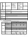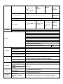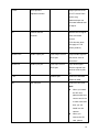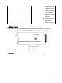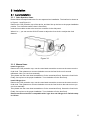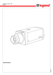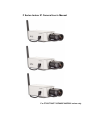
1
F Series Indoor IP Camera User’s Manual
For F725/F726/F715/F665/F645/F625 series only
Welcome
Thank you for purchasing our IP camera!
This user’s manual is designed to be a reference tool for your system.
Please read the following safeguard and warnings carefully before you use this series product!
Please keep this user’s manual well for future reference!
Important Safeguards and Warnings
1.Electrical safety
All installation and operation here should conform to your local electrical safety codes.
We assume no liability or responsibility for all the fires or electrical shock caused by improper handling
or installation.
We are not liable for any problems caused by unauthorized modification or attempted repair.
2.Installation
Do not apply power to the IP camera before completing installation.
Do not put object on the IP module.
3.Environment
This series IP camera should be installed in a cool, dry place away from direct sunlight, inflammable,
explosive substances and etc.
Please open the accessory bag to check the items one by one in accordance with the list below.
Contact your local retailer ASAP if something is missing or damaged in the bag.
Accessory Name
IPC Unit
Lens
Power Adapter
Quick Start
Guide
Warranty Card
Certificate Card
CD
F726/ F725/ F715 Series
F625/F645/F665 Series
Amount
■
■
1
□
■
1
■
■
1
■
■
1
■
■
1
■
■
1
■
■
1
Table of Contents
1
General Introduction ..................................................................................................................6
1.1
Overview ........................................................................................................................6
1.2
Feature...........................................................................................................................6
1.3
Specification ..................................................................................................................7
1.3.1 Performance...........................................................................................................7
1.3.2 Function Specification ..........................................................................................8
1.3.3 Factory Default Setup .........................................................................................11
2
Framework.................................................................................................................................15
2.1
Rear Panel...................................................................................................................15
2.2
Side Panel ...................................................................................................................19
2.3
Lens ..............................................................................................................................19
2.4
Remote Control...........................................................................................................20
2.5
Bidirectional talk .........................................................................................................21
2.5.1 Device-end to PC-end ........................................................................................21
2.5.2 PC-end to the device-end ..................................................................................22
3
Installation .................................................................................................................................23
3.1
Lens Installation..........................................................................................................23
3.1.1
3.1.2
3.1.3
3.1.4
3.1.5
3.1.6
3.1.7
3.1.8
4
Auto Aperture Lens .............................................................................................23
Manual Lens.........................................................................................................23
Remove Lens .......................................................................................................24
SD Card Installation ............................................................................................24
Remove SD card .................................................................................................25
3G Card Installation ............................................................................................26
Remove 3G card .................................................................................................27
I/O Port..................................................................................................................27
System Network .......................................................................................................................29
4.1
General Network.........................................................................................................29
4.2
3G Network .................................................................................................................29
5
6
7
8
9
Quick Configuration Tool.........................................................................................................30
5.1
Overview ......................................................................................................................30
5.2
Operation .....................................................................................................................30
Web Operation..........................................................................................................................33
6.1
Network Connection...................................................................................................33
6.2
Login and Main Interface...........................................................................................33
GUI Operation...........................................................................................................................36
7.1
Main Menu...................................................................................................................36
7.2
Network Setup ............................................................................................................36
7.3
Encode Setup .............................................................................................................37
Wireless Network Access Setup (For W Series Only) .......................................................39
8.1
Wireless Router Setup...............................................................................................39
8.2
IPC Web Network Setup ...........................................................................................40
8.3
Web Setup...................................................................................................................41
FAQ ............................................................................................................................................42
1 General Introduction
1.1 Overview
This series IP camera integrates the traditional camera and network video technology. It adopts
audio video data collection, transmission (wire, WIFI, 3G), storage together. It can connect to the
network directly without any auxiliary device.
This series IPC uses standard H.264 video compression technology and AMR, G.711a/u audio
compression technology, which maximally guarantee the audio and video quality.
This series IPC has mega pixel resolution and supports PoE and 12V DC power. It supports the
wireless network application, bidirectional talk, digital water mark and etc.
It can be used alone or used in a network area. When it is used lonely, you can connect it to the
network and then use a network client-end. Due to its multiple functions and various uses, this
series IPC is widely used in many environments such office, bank, road monitor and etc.
1.2 Feature
User
Management
Data
Transmission
z
Different user rights for each group, one user belongs to one group.
z
Built-in USB port supports TD-SCDMA、EVDO(CDMA2000 1X)、
WCDMA module so that IPC can support mobile communication data
transmission.
Built-in USB port support Wifi module so that the IPC can support the
wireless data transmission.
Support cable network data transmission via Ethernet
Support central server backup function in accordance with your
configuration and setup in alarm or schedule setting
Support record via Web and the recorded file are storage in the clientend PC.
Support local SD card hot swap. Please note SD card can only
memorize the image.
Real-time respond to external alarm input( within 200MS) as user predefined activation setup and exert corresponding message in screen
and audio prompt(allow user to pre-record audio file)
Provide central management server management option so that system
can automatically send alarm notice remotely. Alarm input can connect
to various peripheral equipments.
Provide prompt or alarm option when encounter video loss.
Support SMS(short messaging service) function when alarm occurs.
IPC supports one-channel audio/video data transmit to network terminal
and then decode. Delay is within 500ms (network bandwidth support
needed)
Max supports 10 connections.
Adopt the following audio and video transmission protocol: HTTP, TCP,
UDP, MULTICAST and RTP/RTCP and etc.
Send some alarm data or message via SMTP.
Support web access, widely used in WAN.
Realize IPC configuration and management via Ethernet.
Support device management via web.
z
z
z
Storage
Function
z
z
z
Alarm
Function
z
z
z
z
Network
Monitor
z
z
Network
Management
z
z
z
z
6
z
Peripheral
Equipment
Power
Assistant
Function
z
z
z
z
z
z
z
z
z
z
z
Support peripheral equipment management, each peripheral equipment
control protocol and interface can be set freely.
Support serial port (RS232/RS485) transparent data transmission.
External power adapter
PoE
Day/Night mode auto switch
Auto aperture setup (For 715/F6X5 series only).
Backlight compensation: screen auto split to realize backlight
compensation to adjust the bright.
Support video watermark function to avoid vicious video modification.
Video format support NTSC and PAL.
Support system resource information and running status real-time
display. Support log function.
Use IR receiver to receive the IR signal. (For F726/715/F6X5 series
only).
Electronic PTZ: electronic zoom, direction move (For F725 series only)
1.3 Specification
1.3.1 Performance
Please refer to the following sheet for IPC performance specification.
Specification
Name
Video
Standard
Encode
capacity
IPC-F726
PAL:1f/s~12.5f/s.
NTSC:1f/s~15f/s (Now
it max supports 12.5f/s. )
IPC-F725
One 720+ one HD1
One 720+ one HD1
PAL:1f/s~25f/s.
UXGA (1600*1200)
WSXGA(1600*1024)
Encode Bit
Stream
One 720+ one HD1
One D1+ one CIF
1.3M(1280*960)
720(1280*720)
WXGA(1280*800)
XVGA(1024*768)
QVGA(320*240)
BCIF(720*288)
D1
(704*576/704*480)
HD1
(352*576/352*480)
HD1
(352*576/352*480)
CIF
(352*288/352*240)
CIF
(352*288/352*240)
QVGA(320*240)
UXGA (1600*1200)
Extra stream:
SVGA(800*600)
D1(704*576/704*480)
VGA(640*480)
HD1(352*576/352*480)
QVGA(320*240)
CIF
(352*288/352*240)
D1(704*576/704*480)
QQVGA(160*128)
NTSC:1f/s~30f/s
D1
(704*576/704*480)
SXGA (1280*1024)
QVGA(320*240)
IPC-F6X5
VGA(640*480)
Main stream:
QCIF(176*144/176*128)
IPC-F715
HD1(352*576/352*480)
QCIF(176*144/176*128)
QCIF
(176*144/176*128)
QVGA(320*240)
QQVGA(160*128)
CIF(352*288/352*240)
QCIF
(176*144/176*128)
QQVGA(160*128)
QQVGA(160*128)
720(1280*720)
7
1.3M resolution:
Video
Record
Speed
Network Capacity
Power Consumption
Power
PAL:1f/s-12f/s per
channel (adjustable).
NTSC:1f/s-22f/s
PAL:1f/s~12.5f/s.
per channel
NTSC:1f/s~15f/s
(adjustable).
(Now it max supports
Other resolutions:
12.5f/s. )
PAL:1f/s-25f/s per
channel (adjustable).
NTSC:1f/s-30f/s
per channel
(adjustable).
Max support 10 network users to monitor simultaneously
TCP output capacity 75Mbps
UDP output capacity 85Mbps
Usually it is 4W and
Usually it is 3W and the max value is less than 4W.
the max value is less
than 5W.
DC 12V
PoE(48V DC)
UXGA/WSXGA/SXGA/
WXGA/XVGA:
1f/s to 15f/s per
channel(adjustable)
Other resolutions:
PAL:1f/s-25f/s per
channel (adjustable).
NTSC:1f/s-30f/s per
channel (adjustable).
PAL:1f/s-25f/s per
channel (adjustable).
NTSC:1f/s-30f/s per
channel (adjustable).
Working environment temperature:-10℃~50℃
Chassis internal rising temperature is less than 20℃(When IPC is working ,the chassis internal
temperature deducts environment original temperature.)
Temperature
Working
Environment
Humidify
Dimension(H*W*D)
Weight
10%~90%
58mm*69mm*139mm
500g
1.3.2 Function Specification
Please refer to the following sheet for function specification information.
Note
Specification
F725
F715
Zoom Adjustment
Manual
Lens Control
CCD Video
Process
Focus Adjustment
Manual
Aperture Adjustment
Manual DC
Backlight compensation
control
White balance
adjustment
Contrast ness adjustment
Bright ness adjustment
Electronic shutter control
Color/B&W(Day/Night)
switch
Video
Resolution
Manual/Auto
DC
F6X5
Manual/Auto
DC
F726
N/A
Manual On/Off
Auto
Manual/Auto
Manual/Auto
Auto
Manual/Auto
Manual/Auto Auto
Manual/Auto
Note
The color/B&W (Day/Night) switch here just an electronic switch.
System removes the color elements and reserves the B&W
elements. It is not a filter switch.
UXGA、WSXGA、
SXGA、WXGA、
XVGA、SVGA、
1.3M、720、
VGA、
QVGA、D1、
D1、BCIF、
HD1、CIF、
UXGA、
D1、
QVGA、
HD1、CIF、
8
VGA、QVGA、
D1、HD1、CIF、
QCIF、
HD1、CIF、
QCIF、
QQVGA
QCIF、
QQVGA
QCIF、
QVGA、
QQVGA
QVGA、QQVGA、
720
Video compression
Motion Detection
MPEG4
video
Standard H.264 encode/decode format
compression
standard
Take 18*22 pix as a macro unit. Support 396 detection zones.
Sensitivity level ranges from 1 to 6.
1-ch 12.5f
Dual-stream
Audio
Bidirectional Talk
Audio Listening
Network
1-ch 15f UXGA+1ch CIF
1-ch 25f 720+
1-ch HD1
1-ch 25f D1
+1-ch 25f
CIF
UXGA+1ch
12.5f CIF
Delay within 200ms
1-ch MIC input.
WEB access via IE browser.
PPPoE dial function
DHCP auto get IP address
DDNS
SMTP email function
NTP time synchronization.
DNS domain parse
IP address filter
IP address auto search function
Wireless Network Interface :802.11b/g
Schedule Record
Channel Title Display
Support max 6 periods.
After enabling manual record, no matter system is in schedule or
alarm status or not, system just begins recording.
System automatically enables recording function when alarm
occurred.
When video changes, system automatically enables record
operation.
There are 255 layers.
O is the bottom layer and 255 is the highest layer.
O means completely transparent and 255 is opaque.
Please refer to the above information.
Privacy Mask
Max supports 8 zones.
Local SD storage
Based on SDK network
storage
Based on FTP network
storage
Network alarm/local
alarm output
Local alarm/network
alarm input
Activate alarm via motion
detection or external
input
Support high-speed card/low-speed card
Manual Record
Record
Alarm Record
Motion Detection Record
Time Title Display
OSD
Storage
Alarm
Event
Management
N/A
Supported
1-ch local/network alarm output
1-ch local/network alarm input
Please enable pre-record function when activating the alarm
9
Upload video file or
JPEG file via email、
FTP、HTTP
Send out alarm notice via
email, HTTP and external
port.
Support video short time
buffer storage before or
after alarm
Control
On-line
Upgrade
Device
Management
Upload automatically
Support de-jitter when alarm occurs frequently.
Pre-record is 2Mbytes. Buffer storage video of 5s.
RS485 PTZ control
Support semi-duplex communication way.
RS232
For debug
Network remote upgrade Use upgrade tool.
COM upgrade
Upgrade from network via COM command.
COM control platform
View IPC running status or IPC parameter via COM port.
Network client-end
Log in the client-end software in the PC to monitor IPC.
IPC provides device information, video information, COM setup, record setup, motion detection
setup, alarm setup, OSD information interfaces to modify system setup.
Parameter
Configuration
Log
Water Mark
Power
supply
RESET
IPC provides running information such as user port, log, status, user management, email setup,
date modification.
System can record the important event log record
Record the following information:
System operation, setup operation, alarm event, record management, user management, clear
log.
To avoid vicious video modification.
PoE (For –P series only). Comply to IEEE802.3af standard
DC12V power supply
Support hardware/software/Watchdog reset. Watch dog max supports 35 seconds.
Alarm input port
Port ESD
protection
Analog audio input/output port. Analog video output port
Network port
12V power adapter
Interface
One analog video output port
One audio input port
One audio output port
Two alarm input
ports
One alarm input port
One alarm input
port
Two alarm input
ports
One alarm output port
One network interface(RJ45 10M/100M self-adaptive Ethernet port)
One wireless network interface(For –W series only)
Reserved
One remote control receiver port
10
One SD card port
Support high-speed card/low-speed card.
One 3G card port (For 3G series only.)
Reserved
One red/green running status indication light.
One green network receive and send indication light (Network interface seat has )
Others
One yellow network connection indication light (Network interface seat has)
One green wireless network receive/send indication light. (For –W
series only.)
Reserved
One RESET button
Auto aperture port. (DC drive mode)
Installation
Reserved
Bracket installation
1.3.3 Factory Default Setup
Please refer to the following sheet for factory default setup information.
Function Configuration Item Name
Default setup
Type
F726
F725
General Setup
Date format
Y-M-D
DST
Disable by default
Date separator
‘_’
Encode
Setup
Main
Stream
Extra
Stream
Time format
Language
When HDD is full
Record duration
Device No.
Video type
Channel
Encode mode
Audio/Video enable
General bit stream
Resolution
Frame rate
Bit stream control
Quality
Bit stream value
I frame interval control
Extension Stream
Audio/Video enable
Resolution
Frame rate
Bit stream control
Quality
Bit stream value
I frame interval control
Image Color
Watermark
F715
F6X5
24H
Simplified Chinese
Overwrite
60M
8
PAL
Channel01
MPEG4
H.264
H.264 H.264
Enable audio and video
General bit stream
UXGA
720
720
D1
25
VBR
Good
4096
2048
2048
2048
24
50
50
50
General bit stream
Enable audio and video
CIF
12
25
25
25
VBR
Good
512
50
Brightness:50
Contrast:50
Sautratioon:50
Hue:50
Enable
11
Record Setup
Privacy Mask
Watermark: all
Watermark type: character
Watermark: DigitalCCTV
Never
Time title
Enable. OSD transparent :128
Channel title
Enable. OSD transparent :128
Channel
Pre-record
Time Setup
Ch01
5 seconds.
0:00:00
23:59:59
Period 1:Enable motion
detection/alarm
Period 1: Enable motion
detection/alarm
Sunday
COM01
General
8
1
115200
None
Port 01
Disable
192.168.1.108
255.255.0.0
192.168.0.1
Device factory default name
37777
80
37776
10
Start Time
End Time
Record
Snapshot
COM Setup
Network Setup
Alarm Setup
Week
Option
Function
Data bit
Stop bit
Baud rate
Parity
Ethernet
DHCP
IP address
Subnet mask
Gateway
Device name
TCP port
HTTP port
UDP port
Network user connection
amount
Network transmission QoS
Remote host
Enable
IP address
Port
Email setup
Multiple DDNs
NAS setup
NTP setup
Alarm server
Event type
Alarm input
Type
Setup
Anti-dither
General output
Alarm latch
Record channel
Disable
Multiple broadcast group
Disable
239.255.42.42
36666
Enable
Disable
Disable
Disable
Disable
Local input
Input 01, disable
Normal open
Period:
Start time 0:00:00
End time:23:59:59
Period 1:enable
Week: Sunday
0 second
Disable
10 seconds
1, enable
12
Video Detection
Record latch
10 seconds
Send email
Disable
PTZ activation
Disable
Event type: never
Address: 0
Disable
Motion detection
Ch01, Disable
3
Period:
Start time 0:00:00
End time:23:59:59
Period 1:enable
Week: Sunday
5 seconds
Disable
10 seconds
Disable
10 seconds
Disable
Event type: Never
Address: 0
Disable
Disable
Ch01
EPTZ
EPTZ
DHDHSD1
SD1
1
115200
8
1
None
Disable
Disable
Disable
Disable
Disable
Disable
Disable
Disable
Disable
Disable
Auto. Ch1 (This series device does not
support this function.)
No HDD, Disable
Disable
Snapshoot
Event type
Channel
Sensitivity
Time period setup
Anti-dither
General output
Alarm latch
Record channel
Record latch
Send email
PTZ activation
PTZ Setup
Default and Backup
Advanced
Snapshot
Channel
Protocol
Address
Baud rate
Data bit
Stop bit
Parity
All
General
Encode
Record
COM
Network
Alarm
Video detection
Display output
Channel No.
Record control
Abnormity
Even Type
General
Output
Alarm Latch
Send email
User account
10 seconds
Disable
admin--- password: admin (reusable)
888888--- password: 888888(reusable)
666666--- password: 666666(reusable)
Snapshot
Channel
Snapshot
default--- password: tluafed
Ch01
Scheduled
13
Auto
maintain
Camera Property
Auto Registration
DNS Setup
mode
Frame rate
Resolution
Quality
Auto reboot
Auto delete
old files
1f/s
D1
60%
2.00 each day
Never
Channel
Exposure Mode
Day/Night Mode
Backlight Compensation
Auto Aperture
White Balance
Signal Type
Mirror
Flip
Enable
SN
IP
Port
Device ID
DNS
1
Auto
Color
Disable
N/A
N/A
N/A
Internal input
Disable Disable
Disable Disable
Disable
1
0.0.0.0
7000
Dahua
Alternative DNS
202.101.172.35
Disable
Disable
N/A
N/A
N/A
N/A
202.101.172.35
14
2 Framework
2.1 Rear Panel
This series IP camera real panel is shown as below. See Figure 2-1.
Figure 2-1
Please refer to the following sheet for detail information.
Interface Name
VIDEO OUT
Video output port
Connector
Function
BNC
Output analog video
signal. Can connect to
TV monitor to view
video.
Wireless Antenna
Connect to wireless
Port
antenna to receive
WIFI/3G wireless
signal.
DC 12V
Power port. Input 12V
DC
STATUS
Status indication light
It is to indicate camera
working status:
z
The red light
becomes on
when connect the
15
camera to the
power. The green
light flashes and
then becomes on,
which means
application is
running normally.
Now you can log
in via network.
z
The indication
light becomes off
when you reboot
the system via
software.
z
The green light
flashes when
system is
recording.
z
The red light
flashes when
system is
upgrading.
z
The red light is on
in safety mode.
WLAN
Wireless network
The wireless network
indication light
indication light is to
display wireless
network working
status.
The network indication
light becomes green
when you connect the
IP camera to the
wireless network.
A
RS485 port
I/O port
RS485_A port, control
external PTZ
16
B
RS485_B port, control
external PTZ
1
Alarm input port 1
Alarm input port 1. To
receive the signal from
the external alarm
device.
2
Alarm input port 2
Alarm input port 2. To
receive the signal from
the external alarm
device. (For F725
series only.)
NO
1-ch alarm output
Alarm output port. To
output alarm signal to
C
the alarm device.
NO: Normal open
alarm output end.
C: Alarm output public
end,
RX
Transparent debug
RS232_RX,RS232
serial port
receive end.
TX
RS232_TX,RS232
COM send out end.
G
GND
Ground end
RESET
RESET button
Restore factory default
setup.
When system is
running normally
(power indication light
is green), press the
RESET button for at
least 5 seconds,
system can restore
factory default setup.
17
LEVEL
Auto aperture
Adjust aperture level.
adjustment button
(For F715 and F6X5
series only)
Please always use
nonmetal material tool
to adjust.
IR
Infrared remote
Receive the IR signal
receiver
from the remote
control.
(This function does
not apply to F725
series product.)
AUDIO OUT
Audio output port
Audio output 3.5mm
Output audio signal to
JACK port.
the device such as
sound box.
AUDIO IN
Audio input port
Audio input 3.5mm
Input audio signal.
JACK port.
Receive signals from
devices such as pickup.
LAN
Ethernet port
Connect to standard
Ethernet cable.
SD
SD card port
Connect to SD card.
Note
z
When you install
the SD card,
please make sure
current card is not
in write mode and
then you can
install it to the
camera.
z
When you
remove the SD
card, please
18
make sure current
card is not in write
mode. Otherwise
it may result in
data loss or card
damage.
z
Before hot swap,
please stop
record operation.
2.2 Side Panel
Please refer to the following interface for side panel dimension information. See Figure 2-2.
Figure 2-2
2.3 Lens
Please refer to the following interface for lens dimension information. See Figure 2-3.
19
Figure 2-3
2.4 Remote Control
Please refer to the following interface for remote control information. See Figure 2-4.
Figure 2-4
Please refer to the following sheet for detail information.
Icon
Name
Reset device
Emergency
Function
Reserved for future use
Reserved for future use
20
Reserved
Reserved for future use
Record
Reserved for future use
Alarm arm
Reserved for future use
Alarm disarm
Reserved for future use
Go to safe mode
Exit safe mode
Reserved for future use
Direction buttons
Number switch/Function switch
Number switch/Function switch
Go to the previous
Go to the next
~
Confirm/Menu
button
Go to the menu or confirm current
operation.
Cancel
Cancel current setup
Number 0 to
number 9
Number/password/channel switch
For number more
than 10+
Reserved
Input method switch
Reserved
2.5 Bidirectional talk
2.5.1 Device-end to PC-end
Device Connection
Please connect the speaker or the pickup to the first audio input port in the device rear panel.
Then connect the earphone or the sound box to the audio output port in the PC.
Login the Web and then enable the corresponding channel real-time monitor.
Please refer to the following interface to enable bidirectional talk.
21
Figure 2-5
Listening Operation
At the device end, speak via the speaker or the pickup, and then you can get the audio from the
earphone or sound box at the pc-end.
2.5.2 PC-end to the device-end
Device Connection
Connect the speaker or the pickup to the audio output port in the PC and then connect the
earphone or the sound box to the first audio input port in the device rear panel.
Login the Web and then enable the corresponding channel real-time monitor.
Please refer to the above interface (Figure 2-5) to enable bidirectional talk.
Listening Operation
At the PC-end, speak via the speaker or the pickup, and then you can get the audio from the
earphone or sound box at the device-end.
22
3 Installation
3.1 Lens Installation
3.1.1 Auto Aperture Lens
Please follow the steps listed below for auto aperture lens installation. The interface is shown as
in Figure 3-1 and Figure 3-2.
Remove the CCD protection cap of the device, and then line up the lens to the proper installation
position. Turn clockwise until the lens is fixed firmly.
Insert the lens cable socket to the auto lens connector in the side panel.
When it is ∞, you can turn the ADJUST screw to adjust the focus circle to adjust the focal
distance.
Figure 3-1
3.1.2 Manual Lens
Install C type lens
Remove the CCD protection cap; use the cross-head screwdriver to remove the screw near the
focal circle. Then please turn counter clockwise to move the focal circle out for several
millimeters. Now you can focus manually.
Then please use the cross-head screwdriver to fix the screw back firmly. Secure the focal circle.
Finally, line up lens to the proper installation. Turn clockwise to fix the lens firmly.
Install CS type lens
Remove the CCD protection cap; use the cross-head screwdriver to remove the screw near the
focal circle. Then please turn counter clockwise to move the focal circle to the end and now you
can focus manually.
Then please use the cross-head screwdriver to fix the screw back firmly. Secure the focal circle.
Finally, line up lens to the proper installation. Turn clockwise to fix the lens firmly.
Please note this series IPC is compatible with C type lens and CS type lens. Default setup
is CS lens.
23
Figure 3-2
3.1.3 Remove Lens
Please follow the steps listed below to remove lens. The interface is shown as in Figure 3-3.
Turn the lens counter clockwise and then remove it from the camera.
Unplug the auto lens cable socket from the auto lens connector. If you are using the manual
aperture lens, please skip to the following step.
If there is no lens, please put the CCD protection cap back to protect the CCD.
Figure 3-3
3.1.4 SD Card Installation
Please follow the steps listed below to install SD card. The interface is shown as in Figure 3-4
and Figure 3-5.
Use the screwdriver to loosen the SD card protection screw in the rear panel, and then remove
the SD card protection cap from the camera.
Install the SD card to the camera according to the proper installation position.
Put the SD card protection cap back.
Use the screwdriver to fix the SD card protection cap screw firmly to secure the SD card
protection cap in the camera.
24
Figure 3-4
Figure 3-5
3.1.5 Remove SD card
Please follow the steps listed below to remove SD card. The interface is shown as Figure 3-6.
Use the screwdriver to loosen the screw of SD card protection cap in the rear panel. Remove the
cap from the camera.
Follow the SD card direction to remove the SD card.
Insert the SD card protection cap.
Use the screwdriver to fix the screw to secure the protection cap.
25
Figure 3-6
3.1.6 3G Card Installation
Please follow the steps listed below to install 3G card. The interfaces are shown as Figure 3-7
and Figure 3-8.
Use the screwdriver to loosen the 3G card protection cap screw in the side panel, and then
remove the 3G card protection cap from the camera.
Install the 3G SIM card to the camera according to the proper installation position.
Put the 3G card protection cap back.
Use the screwdriver to fix the 3G card protection cap screw firmly to secure the 3G card
protection cap.
Figure 3-7
26
Figure 3-8
3.1.7 Remove 3G card
Please follow the steps listed below to remove 3G card. The interface is shown as Figure 3-9.
Use the screwdriver to loosen the screw of 3G card protection cap in the rear panel. Remove the
cap from the camera.
Follow the 3G card direction to remove the 3G SIM card.
Insert the 3G card protection cap.
Use the screwdriver to fix the screw to secure the protection cap.
Figure 3-9
3.1.8 I/O Port
Install Cable
Please follow the steps listed below to install the cable. See Figure 3-10.
Use the small slotted screwdriver to press the corresponding button of cable groove. Insert the
cable into the groove and then release the screwdriver.
Remove Cable
Please follow the steps listed below to remove the cable.
Use the small slotted screwdriver to press the corresponding button of cable groove. Remove the
cable out of the groove and then release the screwdriver.
27
Figure 3-10
28
4 System Network
4.1 General Network
Please refer to Figure 4-1 for Wifi and general system connection.
Figure 4-1
4.2 3G Network
Please refer to Figure 4-2 for 3G cable connection.
Figure 4-2
29
5 Quick Configuration Tool
5.1 Overview
Quick configuration tool can search current IP address, modify IP address. At the same time, you
can use it to upgrade the device.
Please note the tool only applies to the IP addresses in the same segment.
5.2 Operation
Double click the “ConfigTools.exe”icon, you can see an interface is shown as in Figure 5-1.
In the device list interface, you can view device IP address, port number, subnet mask, default
gateway, MAC address and etc.
Figure 5-1
Select one IP address and then right click mouse, you can see an interface is shown as in Figure
5-2.
30
Figure 5-2
Select the “Open Device Web” item; you can go to the corresponding web login interface. See
Figure 5-3.
Figure 5-3
If you want to modify the device IP address without logging in the device web interface, you can
go to the configuration tool main interface to set.
In the configuration tool search interface (Figure 5-1), please select a device IP address and then
double click it to open the login interface. Or you can select an IP address and then click the
Login button to go to the login interface. See Figure 5-4.
In Figure 5-4, you can view device IP address, user name, password and port. Please modify the
corresponding information to login.
Please note the port information here shall be identical with the port value you set in TCP port in
Web Network interface. Otherwise, you can not login the device.
If you are use device background upgrade port 3800 to login, other setups are all invalid.
Figure 5-4
After you logged in, the configuration tool main interface is shown as below. See Figure 5-5.
31
Figure 5-5
32
6 Web Operation
This series IPC product support the Web access and management via PC.
Web includes several modules includes monitor channel list, record search, alarm setup, system
configuration, PTZ control, monitor window and etc.
IP camera factory default setup:
z IP address: 192.168.1.108.
z User name: admin
z Password: admin
6.1 Network Connection
Please follow the steps listed below for network connection.
z Make sure the IPC has connected to the network properly.
z IPC IP address and PC IP address shall be in the same network segment. IPC default IP
address is 192.168.1.108. If there is router, please set the corresponding gateway and
subnet mask.
z Use order ping ***.***.***.***(* IP camera address) to check connection is OK or not.
6.2 Login and Main Interface
Open IE and input IP camera address in the address bar.
For example, if your camera IP is 192.168.1.108, then please input http:// 192.168.1.108 in IE
address bar. See Figure 6-1.
Input your IP
address here
Figure 6-1
System pops up warning information to ask you whether install control webrec.cab or not.
Please click OK button, system can automatically install the control. When system is upgrading, it
can overwrite the previous Web too.
If you can’t download the ActiveX file, please check whether you have installed the plug-in to
disable the control download. Or you can lower the IE security level. See Figure 6-2.
33
Figure 6-2
After installation, the interface is shown as below. See Figure 6-3.
Please input your user name and password.
Default factory name is admin and password is admin.
Note: For security reasons, please modify your password after you first login.
Figure 6-3
After you logged in, you can see the main window. See Figure 6-4.
34
Figure 6-4
Please refer to the F Series IPC Web Operation Manual V2.0 included in the resource SD for
detail operation instruction.
35
7 GUI Operation
Connect the IPC to the monitor and then boot up the device. You can use the monitor to view the
analog video output, and use the remote control to realized network setup, encode setup and etc.
Note:
Please use the remote control to highlight the item, and then you can implement the setup.
7.1 Main Menu
Line up the remote control to the IR port in the rear panel. Click Enter button to go to the software
menu operation interface. See Figure 7-1.
Use the left/Right button in the remote control to select the item you desire and then click Enter
button to go to the sub-menu. Click ESC button to exit current interface.
Figure 7-1
7.2 Network Setup
Network setup interface is shown as below. See Figure 7-2 and Figure 7-3(For –W series only).
Please use the Left/Right button to select the item you want to set, use the number or Up/Down
key to set the value. For item of only one option, please move the cursor to highlight the
corresponding parameter and then click Enter button to save current modification.
Please follow the steps listed below.
z Firstly, move the cursor to the port item and then select the corresponding network card
(Figure 7-2). For –W series product, ff you want to use the wireless network, you need to
enable port 02 and then highlight the “preferred” item (Figure 7-3).
z Secondly, click the Right button in the remote control to move the cursor to DHCP item and
then click Enter button to enable DHCP function.
z Thirdly, click the Right button to move the cursor to the IP address item, click Up/Down
button or click number button to set the value you desire. Click Right button you can go on
the next setup. Click Left button you can go to the previous setup. Click Enter button to save
current modification.
z Finally, after you completed all setups, highlight the Save item and then click Enter button in
the remote control to save the latest modification. If you want to cancel current setup, please
highlight the Cancel button and then click the Enter button in the remote control or you can
just click the ESC button in the remote control directly.
You can set one item and then save it for security, or you can complete all setups and then save
all modifications at the same time.
36
Figure 7-2
Figure 7-3
7.3 Encode Setup
Encode setup interface is shown as below. See Figure 7-4.
Please use the Left/Right button to select the item you want to set, use the number or Up/Down
key to set the value. Please click Enter button in the remote control to save current modification.
Click ESC button you can go back to the main interface without saving current modification.
Please follow the steps listed below.
z Firstly, move the cursor to the “channel” item and then select the corresponding channel
number. Please note you can not modify the channel here.
z Secondly, click the Right button in the remote control to move the cursor to “compression”
and “Main stream” item, and then click Enter button to select main stream type and
compression mode. Please note you can not modify extra stream here.
z Thirdly, click the Right button to move the cursor to “Audio”/”Video” item, click Enter button
to enable corresponding function.
z Fourthly, click the Right button to move the cursor to “Resolution” item, click Up/Down button
to select the corresponding value. You can follow the operation here to set other items.
37
Finally, after you completed all setups, highlight the Save item and then click Enter button in
the remote control to save the latest modification. If you want to cancel current setup, please
highlight the Cancel button and then click the Enter button in the remote control or you can
just click the ESC button in the remote control directly.
You can set one item and then save it for security, or you can complete all setups and then save
all modifications at the same time.
z
Figure 7-4
38
8 Wireless Network Access Setup (For W Series Only)
Please note this chapter is for W series only.
8.1 Wireless Router Setup
Please follow the steps listed below for wireless router setup. The following setup interface is
based on TL-WR340G/TL-WR340GD 54M Wireless Router. See Figure 8-1.
z Please modify your PC IP address so that your PC is in the same segment of the wireless
router. Please make sure you can access the wireless router.
z Open the wireless router setup interface. The SSID is the ID of the wireless router in the
network. You can input a self-defined name for your reference.
z Please check the box to enable wireless security function and then select WEP security type.
It includes WEP64 bit and WEP128bit. The WEP key format can be ASCII or hex. Finally
you can set the detail WEP encryption password. These passwords are for you go login the
wireless router. System max supports 4 groups. You can skip current step if your wireless
router does not support encryption function.
z Click save button to save current setup.
Check the box here to
enable security function.
Right now our device
supports WEP type only.
WEP key format supports
HEX and ASCII.
Input four key groups
here.
39
Figure 8-1
Note
The wireless router setup interface may not be the same since there are too many wireless
router manufacturers and product series. But the key setup items are similar. Generally speaking,
you need to login the router interface, and then go to the wireless network parameter setup
interface. Please enable the wireless router function first and then set security mode, encryption
mode, key mode.
8.2 IPC Web Network Setup
Please follow the steps listed below to complete the web setup.
z Please set an IP address to the device and then connect the device and the PC to a wireless
router to establish a LAN.
z In the PC, open the IE and then input device IP to login the device Web. In the network
setup interface, please select port 02 (wireless). Now you can set wireless IP address,
subnet mask and gateway information. Device default wireless IP address is 192.168.0.108.
If you are using wire and wireless network at the same time, please set the wireless IP and
wire IP in two segments. You can go to the local GUI network interface to complete this
setup.
z Finally, you can click save button and then exit the Web. Open the IE again and then input
wireless IP address.
Figure 8-2
Note
40
If you are using the IP address in the WAN, you can follow the above steps too. You can access
the IP address in the WAN first and then set the wireless IP address in the Network interface
(Figure 8-2).
8.3 Web Setup
Please follow the steps listed below to implement Web setup.
z Click SSID search button to search the wireless router available.
z Check the enable box to enable wireless configuration function.
z Double click the wireless router SSID to begin the setup. System can configure the mode
and WEP encryption mode automatically (according to your wireless router setup).
z If the wireless router adopts the WEP encryption mode, you need to set the corresponding
encryption information manually. You can select mode, WEP mode, and key type. Click the
save button to save current setup and then click refresh button to view the latest setup
information. You can skip to the next step if your wireless router does not use WEP
encryption function.
z After setting the wireless router and device parameter, you can remove the device network
cable and then access the device in the wireless mode.
Figure 8-3
Please refer to the Web Operation Manual included in the resource SD for detailed operation
instruction.
41
9 FAQ
Bug
I can not boot up
the device.
Please click RESET button for at least five seconds to restore
factory default setup.
SD card hot swap
Before draw out SD card, please stop record or snapshot first and
then wait for at least 15 seconds to remove the SD card.
All the operations before is to maintain data integrity.
SD
card
times
write
I can not use the
disk as the storage
media.
Do not set the SD card as the storage media to storage the
schedule record file. It may damage the SD card duration.
When disk information is shown as hibernation or capacity is 0,
please format it first (Via Web).
I can not upgrade
the
device
via
network.
The status indication light is shown as red when network upgrade
operation failed. You can use port 3800 to continue upgrade.
Recommended SD
card brand
Kingston 4GB、Kingston 1GB、Kingston 16GB、Transcend
16GB、SanDisk 1G、SanDisk 4G
Usually we recommend the 4GB (or higher) high speed card in case
the slow speed results in data loss.
Electronic PTZ
operation
(For F725 series
only)
Audio function
If you want to use electronic PTZ, please set the protocol as EPTZ.
The device only supports electronic PTZ operation when the IPC
resolution is less than SVGA.
Please use active device for the audio monitor input, otherwise there
is no audio in the client-end.
Note
z
This user’s manual is for reference only. The wireless network function is for W series
only and 3G function is for special series only.
z
Slight difference may be found in user interface.
z
All the designs and software here are subject to change without prior written notice.
z
Please visit our website for more information.
42