1
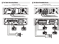
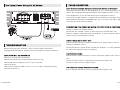
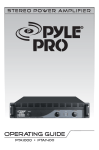
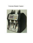
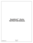
Co m pact C l a ss D F u l l R a ng e H y b r i d A mp l i fi e r
USER ' S MANUAL
PLBA330FRD
PLBA430FRD
PLBA530FRD
FEATURES
CLASS-D DESIGN
Compact class-D full range hybrid amplifer.High efficient power
POWER SUPPLIES
Stiffly regulated PWM power supplies.MOSFET switches maintain rated
power over a wide range of battery voltages.
LPF Crossover Adjustment
Use this adjustment to select the crossover point. Remember thatyou must
select the Low Pass position (LPF) of the crossover adjustment switch first.
The range of adjustment is limited between 30-200 Hz.
HPF Crossover Adjustment
Use this adjustment to select the crossover point. Remember that y ou must
select the high pass position ( HPF ) of the crossover adjustment switch first.
the range of adjustment is limited between 50-250 Hz.
X - OVER Selection Switch
This switch allows you to select the crossover. Use High Pass formidrange or
high frequency speakers. Use Low Pass for subwoofers. In the FLAT position,
neither crossover adjustment knob has an affect.
Bass Boost
The amplifier feature a Quasi Parametric Bass EQ Bass Boost with
adjustments for both Boost Level and Boost Frequency.
BASS BOOST
The amplifier feature a Quasi Parametric Bass EQ Bass Boost with
adjustments for both Boost Level and Boost Frequency. Begin your
adjustments at low volume. Turn the Bass Boost Level control about 1/2 way
up. Next, turn the Bass Boost Frequency up and down.This will take some
tweaking but try to find the setting that gives you a richer and fuller Sound
without over working the subwoofer. Play several different kinds of music to
test your adjustment. You may find you have to go back and make some
changes and compromises to get it sounding right with an assortment of
PROTECTION CIRCUITRY
Protection against thermal, Overload and short circuit conditions.
REMOTE GAIN CONTROL
This amplifier come complete with a compact remote gain controller which
can be conveniently mounted on or under the dashboard of your car.
I NTRODUCTION
Thank you for purchasing the PYLE BLADE Class-D amplifier. Rest assured
you have purchased a quality product designed and engineered to give you
many years of uncompromised musical service.
The BLADE Class-D amplifier has been designed using the latest in
electronic technology available today.
This compact class - D full range hybrid amplifer is the result of advanced high
speed switching technology that overcomes the
less-efficient classAB design. The BLADE Class-D amplifier reflects your
true appreciation for beautiful music reproduction in the mobile environment.
This series amplifier is designed for full range frequency information and
mono low frequency information.
The power supply incorporated into VIBE amplifier is a DC to DC switching
power supply designed to have adequate headroom for even the most
demanding peak and dynamic range found on today's Cds and recording.
PRODUCT SPECIFICATIONS
MODEL
PLBA330FRD
PLBA430FRD
PLBA530FRD
RMS POWER @4Ω
2 * 600W + 1000W
4*450W
4 * 600W + 1000W
MAX POWER @4Ω
2*1200W + 2000W
4*900W
4*1200W + 2000W
RMS POWER @2Ω
2*850W + 2400W
4*650W
4*850W + 2400W
ITEM
PEAK POWER @4Ω
NOT
RECOMMENDED
2*1800W
T . H . D ( Filter = 22KHz )
0.06%
0.07%
0.07%
S/N (A WTG
> 95dB
> 95dB
> 95dB
0.2-4V
0.2-4V
0.2-4V
CROSSOVER RANGE
HPF:50-250Hz
LPF:30-200Hz
HPF:50-250Hz
LPF:30-200Hz
HPF:50-250Hz
LPF:30-200Hz
FREQUENCY RANGE
20Hz-40KHz
20Hz-40KHz
20Hz-40KHz
BASS BOSS
+18dB
@40Hz-100Hz
+18dB@45Hz
+18dB
@40Hz-100Hz
BRIDGED
REF 1W at 4Ω)
GAIN RANGE
DIMENSION
NOT
RECOMMENDED
8.66''(L)*7.40''(W)*1.97''(H) 7.09''(L)*7.40''(W)*1.97''(H) 12.6''(L)*7.40''(W)*1.97''(H)
A MPLIFIER INSTALLATION
1. Find a suitable location in the vehicle to mount the amplifier.
2. Make sure there is sufficient air flow around the intended mounting
location.
3. Bolt the amplifier to the mounting surface.
4. Connect the power ground terminal to the nearest point on the
chassis of the car. Keep this ground wire less than one meter (39'')
in length. Use 4 gauge wire.
5. Connect the remote terminal to the remote output of the head unit
using 14 gauge.
6. Connect an empty fuse holder within 300mm (12'') of the battery and
4 gauge or larger high quality cable from this fuse to the amplifier
Location.
7. Make sure there is no fuse in this fuse holder. Then make the
connection to the “BATT”connection on the amplifier.
8. I f multiple amplifiers are being used, use cables (each with its own
fuse at the battery) or a #0 or a #2 cable from the fuse holder at the
battery to a distribution block at or near the amplifier's location.
9.Connect all line inputs and outputs using high-quality RCA-RCA
Cables.
10. Insert fuse(s) at the battery fuse holder(s).
11. Recheck all connections before powering up.
12. Set all level controls to their least sensitive positions and set all
crossover controls, switches,etc. to the desired frequency or
position.
13. Once the system is powered up , set the volume control on the
head unit to about the 2 o'clock position, and then set all the
FUNCTIONAL
DESCRIPTION
Functional description
PLBA330RFD ( Control terminals )
2
3
4
1
4
5
6
7
8
9
3
2
10
PLBA430RFD ( Control terminals )
1
4
7
9
PLBA530RFD ( Control terminals )
2
3
4
1
4
5
6
7
8
9
amplifiers' level controls
for maximam output level
14. Further fine tuning of the various controls may be necessary to
o btain the desired results.
10
10
Functional description
FUNCTIONAL
DESCRIPTION
1
RCA Line Input --These RCA jacks allow for a normal Left and Right channel signal
input. Simply connect to the source unit using RCA type audio cables, keeping them
away from power wiring wherever possible.
2
HPF Crossover Adjustment-- Use this adjustment to select the crossover point.
Remember that you must select the high pass position (hpf) of the crossover
adjustment switch first. the range of adjustment is limited between 50-250 Hz.
3
X-OVER Selection Switch-- This switch allows you to select the crossover. Use High
Pass formidrange or high frequency speakers. Use Low Pass for subwoofers. In the
FLAT position, neither crossover adjustment knob has an affect.
4
Input Gain Adjustment -- This control matches the preamp stage of the amplifier to your
source unit. This is NOT a volume control. The range is between 20 0mV and 4V.
5
Phase Shift -- Allows you to change the phase of your subwoofer from 0 to 180 degrees
to help compensate for timing differences between drivers.
6
Remote Level Control (subwoofer Only) ---This port is for the remote level control
(included). The control is intended to allow theuser to control the level of gain up to the
maximum adjustmen level set on the amplifier. The control does not add additional
boost, it only attenuates the setting that is fixed at the amplifier's control panel.
7
Bass Boost-Boost--This control adds 0 to +18dB. Be cautious when adding boost to some
subwoofer systems as they may not be handle the additional low frequency boost. In
the 0dB position, no bass boost is added . The LPF must be switched on for the bass
boost to activate .
8
Boost Frequency-- Use this adjustment to select the specific frequency that your
amplifier Bass will boost at 40Hz-100HZ(PLBA430FRD at45Hz only).
9
LPF Crossover Adjustment-- Use this adjustment to select the crossover point.
Remember thatyou must select the Low Pass position (LPF) of the crossover
adjustment switch first. The range of adjustment is limited between 30-200 Hz.
10
Status LED’ s -- These lights indicate when the amplifier is powered up normally and
when there is a protection fault . See the“Troubleshooting” section for details on what
theseuseful indicators can tell you if there's a problem.
11
Speaker Output Terminals-- Connect your speakers to these terminals. Stereo
connections are connected as labeled. Bridged connections use the CH + and CH - as
the two connections.The 2 and 4 channel amplifiers will perform into 2 Ohm stereo loads
or 4 Ohm bridged loads. DO NOT run 2 Ohm bridged loads on these amplifiers!
12
Power Input Connections -- These connections are for input power, chassis ground,and
remote turn-on. Use a minimum of 4 gauge wiring for power and ground connections.
The terminals willhandle up to 4 gauge wiring with no problem whatsoever. Be sure any
wiring that passes through.
PLBA330RFD ( Power terminals )
11
+
SUB
-
12
POWER OUTPUT(MIN 2Ω)
-
CH2
+
-
CH1
+B
+
REM
GND
PLBA430RFD ( Power terminals )
11
-
-
13
BRIDGE(MIN 4Ω)
CH2
CH4
-
+
+
CH1
-
CH3
+
BRIDGE(MIN 4Ω)
12
FUSES 2*25A
+B
REM
GND
+
PLBA530RFD ( Power terminals )
11
12
POWER OUTPUT(MIN 2Ω)
-
CH2
+
-
CH1
+
+
SUB
+B
REM
GND
-
CH4
+
-
CH3
+
13
Power Fuses -- Standard automotive type ATC/ATO fuses are used on PLBA430FRD
amplifiers. Always replace with the correct fuse size. PLBA330FRD \ 530FRD the built in
fuse .
T he Typical
Speakers
Connecting
Scheme
The
Typical
Connecting
Scheme
The Typical
Speakers
Connecting
Scheme
The
Typical
Connecting
Scheme
PLBA430FRD
PLBA430FRD
STEREO 4 CHANNEL FULL
4OHM
BRIDGE(MIN 4Ω)
-
CH2
-
CH4
+
-
CH1
+
CH3
+
BRIDGE(MIN 4Ω)
+
-
4OHM
FUSES 2*25A
+B
REM
4OHM
STEREO HPF WITH MONO SUBWOOFER
GND
BRIDGE(MIN 4Ω)
-
CH2
-
CH4
+
-
CH1
+
CH3
+
BRIDGE(MIN 4Ω)
+
-
FUSES 2*25A
4OHM
4OHM
4OHM
4OHM
4OHM
4OHM
4OHM
+B
REM
GND
4OHM
4OHM
T he Typical
Speakers
Connecting
Scheme
The
Typical
Connecting
Scheme
The Typical
Speakers
Connecting
Scheme
The
Typical
Connecting
Scheme
PLBA330FRD
STEREO 4Ω2 CHANNEL HPF WITH SUBEOOFER
+
SUB
-
POWER OUTPUT(MIN 2Ω)
-
CH2
+
-
CH1
+B
+
REM
PLBA530FRD
STEREO 4 CHANNEL HPF WITH MONO SUBWOOFER
GND
POWER OUTPUT(MIN 2Ω)
-
CH2
+
-
CH1
+
-
CH4
+
-
CH3
+
+B
REM
+
SUB
-
4OHM
4OHM
4OHM
4OHM
4OHM
4OHM
4OHM
GND
TROUBLESHOOTING
The Typical Power Wiring For All Models
HIDH HISS OR ENGINE NOISE(ALTERNATOR WHINE) IN SPEAKER
Disconnect all RCA inputs to the amplifier(s)-if hiss / noise disappears, then
-
BRIDGE(MIN 4Ω)
CH2
+
-
CH1
+
FUSES 2*25A
+B
REM
GND
plug in the component driving the amplifier and unplug its inputs. If hiss /
noise disappears, go on until the faulty /noisy component is found.
It is best to set the amplifier’s input level as insensitive as possible. The
-
CH4
-
CH3
+
BRIDGE(MIN 4Ω)
+
best subjective S/N ratio is obtainable this way. Try to drive as high a signal
level from the head unit as possible.
PROTECTION LED COMES ON WHEN THE AMPLIFIER IS POWERED UP .
Check for shorts on speaker leads.
Check that the volume control on the head unit is turned down low.
Remove speaker leads,and reset the amplifier. If the Protection LED still
comes on,then the amplifier is faulty.
AMPLIFIER(S) GETS VERY HOT.
Check that the minimum speaker impedance for that model is correct.
TROUBLESHOOTING
Check for speaker shorts.
Check that there is good airflow around the amplifier. In some applications,
Before removing your amplifier, refer to the list below and follow
an external cooling fan may be required.
thesuggested procedures. Always test the speakers and their wires first.
DISTORTED SOUND
AMPLIFIER WILL NO POWER UP.
Check for good ground connection.
Check that the Level control(s) is set to match the signal level of the head
unit.
Check that remote DC terminal has at least 8 . 5 v DC.
Check that all crossover frequencies have been properly set.
Check that there is battery power on the +terminal.
Check for shorts on the speaker leads.
Check all fuses.
Check that Protection LED is not lit. If it is lit, shut off amplifier briefly
HIGH SQUEAL NOISE FROM SPEAKERS.
and then repower it.
This is always caused by a poorly-grounded RCA patch cord.
PYLE AMPLIFIERS
CAR AMPLIFIERS