1
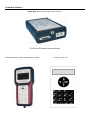
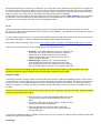
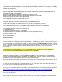
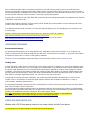
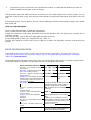
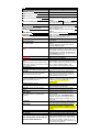
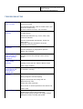
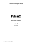
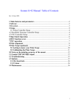
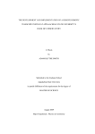
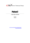
Pulsar2
user’s manual
Version 5.97
09/05/15
http://www.geminitelescope.com/pulsar-goto-controllers/
Controller Pulsar 2
Driver Unit, Motor, Power and Encoder connector
5,5/2,5mm DC socket, center positive
Hand Controller Ver2 with integrated GPS Antenna
Hand controller Ver1
Index
SAFETY.............................................................................................................................................................4
GENERAL.........................................................................................................................................................4
QUICKSTART...................................................................................................................................................4
Hand Controller Menu navigation..................................................................................................................4
Information on the Display of the Ver1 Hand Controller...............................................................................5
Information on the Display of theVer2 Hand Controller................................................................................6
Initializing.......................................................................................................................................................7
USING THE INTELLIGENT FEATURES.......................................................................................................8
Homing position.............................................................................................................................................8
Absolute Reference (with encoders fitted to the mount axis, index signal available)....................................9
Flip Correction (German mount)....................................................................................................................9
Swap tube (Meridian flip).............................................................................................................................10
Pole Crossing................................................................................................................................................10
Go To............................................................................................................................................................10
Using your GPS............................................................................................................................................10
Polar align.....................................................................................................................................................11
Remote Operation.........................................................................................................................................11
ASTROPHOTOGRAPHY...............................................................................................................................12
Guiding hints................................................................................................................................................12
USING PULSAR2 WITH A PC......................................................................................................................13
Upgrading the firmware (Web and USB mode)...........................................................................................13
PROGRAMMING PEC...................................................................................................................................14
Hints for programming PEC.........................................................................................................................14
HAND CONTROLLER MENU......................................................................................................................14
TROUBLESHOOTING...................................................................................................................................17
KEY TO THE ICONS OF THE KEYBOARD...............................................................................................18
LX200 COMPATIBILITY..............................................................................................................................18
AUTOGUIDER PORT....................................................................................................................................18
AUXILIARY PORT (8 PIN)...........................................................................................................................19
CATALOGUE DATA UPLOAD....................................................................................................................19
HARDWARE OPTIONS.................................................................................................................................20
SAFETY
The unit is protected against reverse polarity,
short circuit of the motor cables and
overvoltage. The power cable is fused at
6,3Amp (slow). Please do not connect or
disconnect cables under tension! If you feel
vibration at the DEC motor in standstill, your
power supply is noisy. The unit runs from 12 24V DC (max recommended value 18V) and
draws 3A max during a GoTo. (depending on
motor parameters)
There is a low voltage warning below 10V.
Please use overvoltage resistant optical
isolators when connecting the USB and serial
ports to a PC. The unit is NOT designed for
use in condensing humidity conditions. For
longer periods of bad weather keep it
indoors or use a dehumidifier!
AG, AUX, Hand, LAN, USB ports shown
GENERAL
Pulsar2 is a universal drive controller that can be user programmed for a wide range of mounts fitted with servo or
bipolar stepper motors. It will work with motors only (steppers) or motors + incremental (5V quadrature) encoders.
The standard unit delivers 2A/channel, a custom version is available with 4A capacity, with active cooling. The unit
is LX200 and ASCOM compatible, thus you can use it with your favourite Planetarium Program (Cartedu Ciel, Guide,
Desktop Universe,The Sky, etc) and other sw like PemPro, CCD Autopilot, etc..
Pulsar will work as a standalone driver using the hand controller or connected to a PC (no hand controller is
needed). If connected to a PC Pulsar2 can be reached through the ASCOM platform (driver must be installed) or by
setting the mount type to LX200 (non GPS) or via the Pulsar Commander
(http://www.geminitelescope.com/download.html) and the LAN based virtual hand controller.
To start using Pulsar2, connect the hand controller, the cables to the mount and power. To move the telescope
select the desired speed (see below) and press the joystick. There is no power switch, you will either unplug power
or send the mount to homing and leave it powered until next use. Pulsar2 needs to be programmed for your mount
(mount and user parameters on p14) before it can perform correctly. PEC on Pulsar2 will only work if the dedicated
encoder is fitted to the RA worm.
Here is a link to using Pulsar2 with MaximDl http://www.geminitelescope.com/Manuals/P2_MaxIm.pdf
Detailed info on connector pinout: http://www.geminitelescope.com/Manuals/GeminiPulsar2PinoutInformation.pdf
QUICKSTART
Hand Controller Menu navigation
Use the keypad to reach the menus. The North and South push of the Joystick (js) navigates the menu up and
down, the West push is Enter (yes), the East is Esc (no). The button CE also has the Esc function. Icons give a clue
to the menus. The controller has a multi level menu structure. See the illustration below and also “KEY TO THE
ICONS OF THE KEYBOARD” for more info.
example1 – how to set the goto speed.(setting a value in the menu)
left click js to escape the init menu,Press key 6 ( parameters), right click js, down(S) click js 4 times (GoTo speed),
right click js, the character with the underscore is waiting to be changed, to change hit the appropriate key (eg 7).
As you type, the cursor moves on. To return to the previous character sclick js down(S). When finished editing the
value, right click js and repeat the editing for the dec speed.Right click js when done. Left click js to escape the
user menu.
Example2 – how to change RA motor direction (choosing one of two values)
left click js to escape the init menu,Press key 6, up(N) click js (mount parameters), right click js, down (S) click js 3
times (Rotation L/R), right click js, the cursor in the buttom line shows which value is actually selected. To accept
without change click js to the side where the cursor is. To change, click js to the opposite side respect to the
cursor. Left click js to escape from the menu.
Example3 – how to select the active speed (selecting from several values)
left click js to escape the init menu,Press key 0,up or down click js until the desired speed is displayed, right click js
to select the desired speed.
Guide
speed
Merid flip
(3sec)
Progressive
speed
Setup menu (user, mount,
system parameters)
Parking
(3sec)
DEC motor
inversion
PEC Menu
Quick recalibration
after a goto
Init menu (catalogue star ,
RA+ DEC,set or check
time and date)
Track rate
selection
Joystick
speed
selection
GoTo menu
(catalogue, RA +
DEC, ALT + AZ)
Information on the Display of the Ver1 Hand Controller
The 2x16 character LCD shows Right Ascension (hh,mm,ss and decimals) and Declination (dd,mm,ss). Please note
that the last digit may change abruptly due to rounding errors!
R/D
p
Right Ascension and Declination of the actual position
PEC ON.
r
e/w
S
refraction correction ON.
shows which side of the Meridian the tube is.
Stopped (autostop function, select Sidereal rate to exit!).
E
H
Error (motors stopped after reset or power failure), to exit select
sidereal speed in the rate menu
Pulsar is in home mode
@
!
Low voltage.(together with an acoustic signal)
signal from PEC encoder received.
If you press the side button (maplight) the RA worm position counter value appears at top left and the effect of
refraction is removed from the values of the coordinates (for information only, values are not actually changed)
IMPORTANT NOTE
Before first use you must check and enter correct date and time (in UT) and your geographical
Lat/Long in decimal format. This is necessary for the correct operation of the driver.
Information on the Display of theVer2 Hand Controller
Ver2 Hand Controller has an integrated GPS, if enabled from the user menu/read GPS, this will update the above
parameters.
On the Ver2 Hand Controller press and hold button 7 to turn the maplight on. You must escape from the rate
menu afterwards.
Top row, from left to right
date/longitude, GPS signal ok, time/latitude (time and position info is showed blinked every 3 seconds)
Bottom row, from left to right
Error or Homed, low battery, stopped, PEC, tracking rate (sid), active speed
Graphical aid for initializing a German mount
Initializing
Initializing - this is the first step of use. It aligns the telescope with the equatorial coordinate system. Pulsar2 uses a
one star alignment. You must do it every time you set the telescope up in a new position. Polar align the mount
first! For permanent setup it is enough to do it once (if you shut down by homing the mount).
You need four information for a correct init.
1 rotation of the RA axis – the mount must slew West if the joystick is pressed to the West, if not, change rotation in
the Mount Parameters/Rotation menu
2 rotation of the dec axis – pressing the joystick North must move the OTA North. If not, long press (3s) the N/S button
to change motor rotation.
3 The star (or coordinates) you are pointing at
4 The side of pier/meridian where you have placed the OTA.
Using Autoinit (this is the default menu after switching the controller on):
check the rotation of the dec axis as prompted,
align OTA at the meridian, or due South in other words,
align OTA at cca DEC=0 degree (the equator, OTA at right angle to the hour axis)
mount starts to slew to the nearest reference star
when stops, center the star in the finder and press button 9 as prompted,
tell which side of the pier the OTA is. (NOT the star)
Scroll
up/down to
select the
menu
Flow chart of the Init process using an arbitrary star from the database or coordinate entryATTENTION!!!
A German Equatorial mount will not work properly without this last piece of information. You must enter East or
West via the hand controller or the virtual hand controller. You can sync from a planetarium sw or Maxim later on,
to maintain pointing precision. Fork Mounts can start with a simple sync as well.
Please always initialize the mount in the Southern half of the sky (from E to W)!
A useful link: http://www.youtube.com/watch?v=PtAfKWscf80&feature=youtu.be
USING THE INTELLIGENT FEATURES
The features covered in this paragraph are: Homing position, GoTo, Swap tube, Flip correction, Absolute reference,
Alignmaster, Pole crossing, GPS use, Remote operation.
Homing position
Homing – the mount is sent to a previously defined position and all motions are turned off. Power can be turned off.
Parking – the mount is stopped where it is at the time of the command.
Pulsar has full Homing support but Parking can only be achieved by selecting “still” rate. Unpowering leads to loss of
position in this case.These two concepts are sometimes used incorrectly (in the literature and the manual).
Home position is where the telescope/mount is left when out of use. When the unit is switched ON or is un-homed
it is ready for use without initializing. It is a necessity in an observatory but useful in the field too. You can also
leave the unit powered while homed.
To program the homing position:
1 Initialize (on a star in the Southern half of the sky) if not
yet done
2 Slew the mount to the desired homing position (the tube
must point in the Southern sky and at least a few degrees
above the horizon)
3 Enter the Setup/User Parameters/Home position menu
and save the position
When you finish the observing session press the Home button for 3 sec. and the mount goes to its homing position,
then stops the motors. If you have enabled refraction correction there will be a small motion after the motors have
stopped - this is the compensation for refraction.
You can also home/wake the mount using PulsarCommander or any other suitable sw that uses the Ascom
platform.
Now you can switch power OFF or alternatively, leave it On. Power consumption will be minimal in standstill.
To start a new session simply switch power ON, wake the mount and go! If you have left power on, press the home
button for 3 sec. To enhance positioning accuracy you can fine tune the internal clock (see the Hand Controller
menu overview).
The home – wake cycle
Note:
please avoid a precisely N-S position of the DEC axis as home
position!
This may lead to false E/W information at startup. If you have
Pulsar2 goto mode selected in user/goto mode menu, homing will
always put the OTA on the side of pier OPPOSITE of the celestial
position. E.g. if the OTA points in the East, the OTA will sit on the
Western side of the pier (German mount). To disable this feature
use horizon mode goto.
Absolute Reference (with encoders fitted to the mount axis, index signal available)
If you are using a mount with incremental encoders that have an absolute position signal (one in each full rotation)
you can use this to initialize the mount without finding a star. This is useful in remote operation. You will need to
watch the mount to be successful (IP cam). This is how to use this feature. This video shows the procedure with a
G53F: http://www.youtube.com/watch?v=0RQyp3Hnb08&feature=youtu.be
Initialize the mount as you normally would.
Enter the Mount Parameters/Set reference menu and follow the instructions on the LCD. The aim is to rotate the
axes until the encoder signal has been found.
When finished, exit the menu.
From now on you are able to initialize the mount without stars.
Enter the User parameters/Get reference menu and follow the instructions on the LCD. The procedure is similar to
the above but now the previously saved positions will be recalled.
More on the position of the reference signal is in the mount manuals.
The RA axis is factory adjusted to have the encoder reference within +/-1 hours of the meridian. There is a tutorial
video at http://www.geminitelescope.com/gemini-german-fork-mounts-goto-manuals/
Flip Correction (German mount)
If the OTA optical axis is not perpendicular to the declination axis a meridian flip will be imprecise. In the extreme
vicinity of the Pole you will not be able to reach your targets if this error is present. However, up to 85 degrees
Pulsar2 offers the possibility to correct for this error by first learning it. Enter the Flip correction menu in Mount
parameters and follow the instructions. P2 will automatically select a suitable star that you can precisely center
and then do the flip. After re-centering the star the correction is saved. Once a value has been saved the feature is
active. If you want to disable it re-run the learning routine without making any corrections. This will save zero as
correction value. There is a tutorial video at http://www.geminitelescope.com/Manuals/flip.swf.html
Swap tube (Meridian flip)
This command takes the tube from one side of the mount to another. Swap tube is activated by pressing button 1
for 3 sec. After the flip is completed the telescope points at the same position as before.
To have an accurate Swap tube it is important to check the orthogonality (at 90 degree) of the DEC and tube
optical axis (see the G-41/42 manual for details) or program flip correction. A precise polar alignment is a must.
Alternatively you can set the correction in the Flip correction menu in Mount parameters. The error saved will be
used to correct all goto-s which include swapping of the tube. This correction will not work over 85 deg declination.
If the DEC axis starts turning the tube when the RA motion starts the tube might hit the mount. To avoid this there
is a programmable delay for the DEC motion. This is programmed in the User parameters menu.
Pulsar2 will NOT stop at the Meridian or make a flip. Control programs like CCDAutopilot are responsible for this
task. Pulsar2 will flip if the object is past the Meridian, the OTA is West of the pier and the control software tells it
to slew to the current coordinates (resends the slew command).
Pole Crossing
Reaching the Northern sky may be very difficult if you must rotate nearly 180 degree in RA. Instead, crossing over
the Pole provides simple access. When you give a GoTo command the software optimises the route and decides if
it is more economic to approach the target by crossing the Pole or rotating the Hour axis and staying on the same
side of the Pole. If you have a fork mount this feature will automatically be disabled.
The direction of pole crossing is set in the Setup/User Parameters/Pole crossing /Tube rotation menu that defines
the direction of the declination slew. With cables at the sky end (Newtonian) you will want to slew North, with a
refractor or SC to the South. This way you can avoid tangled cables.
Go To
German equatorial mounts may not provide free access to all sky positions because the telescope can hit the
pier/mount (or the mount hits itself) as it moves away from the Meridian. To avoide this risk select Pulsar2 mode in
the User Parameters menu.
To make a goto with Pulsar2 you can use the internal data bases (see data base upload at the end of this manual),
enter directly RA+DEC, or use the LX200/Ascom interface and a Planetarium program.
The tutorial video for making a goto is here. https://www.youtube.com/watch?v=PtAfKWscf80&feature=youtu.be
Pulsar2 has the following GoTo modes (selectable in user parameters menu):
1 horizon – commands below the horizon are rejected. The
mount will not cross the North line however, it will turn
back instead, to avoid making more than 360 deg
rotation. Select this if you use a fork mount or do not
need a meridian flip at all.
2 Pulsar2 Logic – pulsar2 logic – an advanced goto
management that selects the optimum track for each
goto. It always puts the OTA on the side of pier opposing
the sky position (West of the pier for an object in the East)
.
Note: if you wish to start imaging an object in the East with the OTA East of the pier you must slew to the object
manually, using the joystick or initialize in the east and select “horizon” as goto mode.
Using your GPS
The Pulsar2 controller accepts serially connected GPS units using the (4800 baud) NMEA protocoll (a GPS reciever
is not sufficient!!). Pulsar2 will ask for the UT and geographical coordinates if prompted. This feature allows for the
trouble free use of the intelligent features when you are travelling to dark sky locations. You will need a special
cable for connection. The 8 pin Aux (iliary) connector has the necessary contacts. No power is available here for
the GPS.
The Ver2 hand controller has a bult in GPS unit that will find the coordinates and time after each startup if enabled
in User Parameters/Read GPS menu.
1 Make sure that you have selected NMEA 4800 baud as the
communication protocol (Setup/Interface menu on the
GPS)!
2 Let he GPS collect the navigation signal, connect it to the
Pulsar2 Aux port (with the adapter)!
3 Enter the GPS menu (user parameters). Pulsar will
acknowledge GPS data. Now you can remove the cable
and use the driver.
You will need a dedicated cable ( available from Gemini or DIY) to connect your GPS to Pulsar2 with the serial cable
avilable from the GPS manufacturer.
Polar align
This is an algorithm based on the Drift method. It selects suitable pairs of stars for adjusting azimuth first, when done,
for elevation. For elevation adjustment you have the options of the Eastern or Western sky, according to the visibility.
Workflow of the alignment.
Enter the Polar Align menu and after the first goto terminates, center the star accurately (to better than 1 arcmin).
By pressing 9 you enable the second goto, always from East to West.
Center the star again as you did before.
By pressing 9 the error is saved and an instruction for adjustment is given.
By presing 9 you tell Pulsar2 having done the adjustment, and there is a goto again.
Do as before, center and press 9. This is repeated again.
Based on the error new instructions are given.(more, overdone, wrong knob)
This is repeated until the error is smaller than 2 arcmin.
Now the elevation routine starts by asking for the part of sky to work in (East or West).
The above procedure is repeated, again until the error is smaller than 2 arcmin.
To exit at any time just do not center at the end of the goto, which corresponds to zero error.
For more precision run the alignment twice.
The method works with any mount, the drawback is that you decide the initial amount of adjustment.
You should be aware that GoTo errors are the result of:
1) polar misalignment
2) centering errors in the eyepiece (e.g.:diagonals)
3) perpendicularity errors of the axes (excluded here by moving practically in RA only)
4) database errors and atmospheric refraction (Jnow star coordinates should be used)
5) encoder resolution limits
6) mechanical flexture
Remote Operation
The German Equatorial mount is not the best choice for a remotely operated telescope but the P2 goto logic
provides safe access to all sky positions. The only drawback - compared to fork mounts - is the longer GoTo time in
some cases and the reduced pointing accuracy that is the result of auxiliary motions.
It is recommended to use reduced GoTo speeds (e.g.:RA300, DEC400) and lightly locked slip clutches in remote
mode. If refraction correction is used, the correction will be executed within 10 sec of the last GoTo. If you start an
end of slew exposure without a delay the image might be trailed. Use the Ascom driver with observatory
automation sw.
It is necessary to use optical isolators on serial links in the observatory. All electronic devices must share a
common protective grounding. The pier or mount should also be grounded.
Below is a guide with suggested steps of a (remote) permanent setup, based on a G53F mount.
Decide on the mode of connection. You have USB (plug and play but in case of failure must be unplugged and
plugged), serial (stable but you need a special cable and an RS232 port on the PC, detailed in the FAQ) or virtual
serial over LAN (you need to install the driver, found on the downloads page)
Ascom setup: in the Ascom setup dialog window choose Generic Hub as telescope. Next, configure Generic Hub to
have Pulsar2 as telescope. This way several third party programs can access Pulsar2.
In case you use a German mount, in MaximDL set “Auto pier flip” and in the guider setup dialog set “change X,Y”
(upon pier flip) and “automatically apply spin control changes”
Polar align the mount either with the polar finder or your preferred method. A precise albeit not simple method for
polar alignment is found here (doing something right is most of the time a bit complicated :-)
http://www.astrosurf.com/c2a/english/support/help/Html/Acquisition_d_images_et_methode_de_King.htm
Note: the fact of no dec drift at the meridian is not a sufficient sign of good polar alignment!!! The elevation of the
polar axis can still be out.
Make a one star reference as described in this manual. Now you are synced to the Equatorial coordinate system.
Save a Homing position (this is a software level homing, not with sensors) taking care not to point below the
horizon and according to flip rules (the OTA is always on the opposing side of the pier respect to where it points)
Homing and waking is available if the mount is shut down normally. If it shuts down due to power loss, you can still
use the absolute reference of the encoders, if you have programmed it before.
Program flip correction for your OTA. Note: flip correction has to be reprogrammed after any adjustment to the OTA
(collimation, new camera, etc).
Calibrate the absolute reference of the encoders (G53F, Mofod only) as described in mount's manual and in this
manual. Check out also the demo videos.
The LAN based virtual hand controller is a useful tool that will always work. For installing see the manual on the
manuals page.
Gemini is offering safe remote boxes that protect your telescope under all conditions.
http://www.geminitelescope.com/robotic-observatory-telescope/
This diagram explains connections between Pulsar2 and other parts of the system:
http://www.geminitelescope.com/Manuals/connect1.pdf
ASTROPHOTOGRAPHY
Recommended settings
For guided astrophotography set a guide speed of 1-5, depending on the pixel resolution! (1 for 1"/pixel) Your
system is well tuned if the residual guiding errors after each correction do not exceed 0.1 - 0.3 pixel. The smallest
accepted correction time is 0,01sec. Pulse guide is available.
The Stop Current (Setup/Mount parameters/Stop current) should be close to the Tracking Current.
Guiding hints
A pixel resolution smaller than 1"/pixel will not result (under normal sky conditions) in more image detail but more
trouble and longer exposures only. It is strongly recommended NOT to go below the actual seeing conditions with
the image scale. Alternatively you should set the low threshold for guiding at a higher value during poor seeing
conditions. The reason is that seeing changes star positions faster than guiding, so frequent guiding will increase
blurring rather than decreasing it. Seeing should be evaluated with the actual imaging instrument as it will vary
with aperture (changes significantly above cca. 15cm due to the size of air cells).
If the guide sw is doing automatic calibration, the measured speed should be decreased by cca 20% for best
results. If this is not possible, increase the guide speed in Pulsar2 after making the calibration. In case of
overcorrection, decrease agressiveness.
For unguided photography program the PEC, use Refraction Correction and set the Stop Current at a value within
10% of the Tracking Current or the same.
To get the highest possible tracking precision, programming the PEC at the actual sky position is recommended.
Before using an autoguider cable make sure that it has the correct pinout and orientation! An alternative to cable
guiding is the USB/serial Telescope connection which gives better results
PEC AND Autoguiding is supported in Pulsar2. There is a comprehensive article on Autoguiding at
http://www.geminitelescope.com/gemini-german-fork-mounts-goto-manuals/
USING PULSAR2 WITH A PC
Models with a DC 5,5mm power socket do not need a driver for Win7 and above
It is necessary to use optical isolators on serial links in the observatory.
First install the USB driver (available at the Pulsar2 site).It is compatible with Win XP and Win7 (32 and 64 bit).
Tutorial: http://www.youtube.com/watch?v=iwV-0tudPJQ&feature=youtu.be
Check in My Computer/Properties/Hardware/Device manager the number assigned to the virtual COM port and set
this number in Pulsar Commander or any other softare that needs to connect to Pulsar2. It is recommended to set
the computer time to UT, the time format to 24h, to disable daylight saving time correction and regional settings to
UK. Only one program at a time can connect to Pulsar2 (unless you use a HUB like Ascom or MaxPoint)
Here is more info on possible connections: http://www.geminitelescope.com/Manuals/connect1.pdf
Detailed info on connector pinout: http://www.geminitelescope.com/Manuals/GeminiPulsar2PinoutInformation.pdf
You have the following choices for controlling Pulsar2 over the USB/serial port
1 Pulsar Commander – to load databases, set parameters,
homing and
waking, etc.
2 The ASCOM platform, after installing the Pulsar ascom
driver (available from the downloads site)
3 Any planetarium software, either by selecting LX200 (non
GPS) or
ASCOM telescope.
Upgrading the firmware (Web and USB mode)
The preferred upgarde mode is the webupgrade which is Operation System independent:
http://www.geminitelescope.com/Video/p2_webupgrade.wmv
or http://www.geminitelescope.com/Manuals/P2webupgrade.pdf
USB upgarde procedure (with ver 5.40 and above accessible only as forced upgrade, see the Pulsar FAQ)
Do not attemp to USB upgrade a DC power socket version Pulsar2!
Install SamProg (available http://www.geminitelescope.com/gemini-pulsar-downloads-driver-ascom-firmwaredatabase/will work under WIN XP only) on the PC. Get the latest binary file (4.xx for hardware 1.1 and 5.xx for
hw2.2) from the link above. Then proceed exactly as written below:
1
2
3
4
5
6
7
8
9
10
11
12
13
Switch Pulsar2 ON
In the Setup/System/Upgrade menu select Yes
wait cca 10sec, until you hear a double beep
Switch Pulsar2 OFF
connect Pulsar2 to the USB port of the PC
Switch Pulsar2 ON
open SamProg (you must see: Active connection 1)
browse and select the latest binary file
click „write flash” in SamProg
wait until done
click „exit” in SamProg
switch Pulsar2 OFF and ON
you are ready now (your settings and PEC remain
unchanged)
Please read also the PulsarFAQ before starting the upgrade.
http://www.geminitelescope.com/Manuals/Pulsar_FAQ.pdf
PROGRAMMING PEC
PEC will work only with an installed worm encoder, standard on Gemini G4X mounts.
To program PEC you have the following options.
1
Use the hand controller to enter the PEC/New Pec menu and guide manually until you hear the double
beep. Alternatively you can guide with an autoguider. In this case the autoguider must already be guiding
when you enter the PEC menu. You may use the virtual hand controller of Pulsar Commander for the above
operation.
2
Use PemPro to get an accurate PE curve and load this to Pulsar. You will need the latest Ascom driver for
Pulsar2 installed and the latest version of Pempro.
During the learn period the display shows the corrections you have made and the worm counter position. You can
check the counter position at any time during normal tracking by pressing the lamp button at the side of the hand
unit.
The learning period is 1 worm rotation. There is a 10 sec waiting period before learning starts (beep) and a double
beep at the end.
Hints for programming PEC
Choose a night with absolutely no wind and good seeing!
Use a crosshair eyepiece with at least 500x magnification!
Position the telescope around 0 deg. Declination and near the Meridian (PE is the largest here, but drift due to
refraction is small)!
Polar align precisely, make a reference and enable refraction correction!
Set the Guide speed to match your magnification (e.g.: 500x - 3 )!
The PEC learn algorithm accepts input from the USB port (LX200), the autoguider connector and naturally the
joystick.
HAND CONTROLLER MENU
In the tables below the left column contains menu names and short explanation. The right column offers an
explanation of the function. The expression "hotkey" refers to the appropriate keyboard buttons. The default
values are in bold characters.
The first table contains the parameters of the mount. You find the data in the manual or consult the manufacturer!
The default setting is G-40/41/42. The Microstep resolution is managed automatically.
Mount Parameter (hotkey 6)
Reduction - Total reduction of the
drivesystem.
MainGear - Reduction of the main
gear, used for PEC purposes.
MotorRes - step/rev resolution of the
stepper motors.
Rotation L/R - This defines the default
rotation of the motors. Will depend on
actual wiring of the motors. Set it so
that tracking is correct.
MountType
TrackCurr - Tracking current (used up
to 2x
tracking speed)
GoToCur – The current applied to
motors in GoTo.
StopCur – The current applied to
motors in
standstill
Encoder res – Incremental encoder
resolution
Motor Type - The motor used on the
mount
Red autoset – Reduction automatic
setting
RA
100 – 432 - 10000
DEC
432
100 – 432 - 10000
-----
100/200/400
100/200/400
Left/Right
On hotkey 4. for
DEC.
Germ/Fork /AltAz(F disables swap tube
and E/W of Meridian menu in Initialize,
German sets goto mode to Pulsar2)
800 mA (600 is the recommended
minimum)
1000 mA
400 mA (Should not be much smaller
than
tracking curr. to avoid jump at start.)
The encoders of the servo motors and
the independent encoders of the mount
can be specified here.
Stepper or Servo
Finds the total reduction of the mount if
encoders are fitted. Indispensable for a
friction drive like G53F or MoFoD.
Flip corr set - saves flip error for
correction
Set reference- saves the absolute
position info of the encoders (if fitted)
Polar align– an iterative quick drift
method
Follow the instructions on the LCD
Inhibited over 85 deg declination.
Follow the instructions on the LCD
A polar alignment aid. Follow the
instructions on the LCD.
The table below is an overview of all other (user dependent) hand controller menu functions.
Menus in red are ready after Initializing and correct parameter entry (Init, E/W, Lat/Long, Time) only.
Function
Description
User Parameter Setup - (hotkey 6 and
down)
Guiding speed
Center
Find
Slew
GoTo speed Can be set separately for RA
and DEC.
Ramp All telescopes must accelerate and
decelerate. Otherwise the mount will be
damaged soon.
Backlash compensation
RA
DEC
1-9 (9 = sideral)
10 (1 = 6x sideral)
20
50
Max 999(4,2deg/sec)
Max 999 (4,2deg/sec)
1-9 (1=small
acceleration)
1-9 (9=higt
acceleration)
Swap Tube delay
Pole Crossing
Tube rotation North/South
Latitude-Longitude in decimals Your
observing site's data. The optional GPS
module updates it automatically.
Autostop Local Enter the distance West
of the meridian in Hours, Mins, where you
want the mount to stop. Enable the
function and tracking will stop at the
preset meridian distance.
Home pos.save
This is the sleeping position of the
telescope in your
observatory. Slew the scope to this
position, enter the
menu and save! Works only with valid
geographical
position and time.
Active speed (only with hotkey 0)
Selects the active speed for
Refraction correction (this is the real
time King rate in both directions, plus
correction for GoTo positioning)
Guest mode enter your password (four
digit) and
select ON. Only the joystick slew function
is active now.
Umod sp.lim Stepper driving mode
limiting speed.
GoTo mode Selects goto logic
Read GPS prompts Pulsar2 to read time
and position from a GPS.
Get refence initializes the mount based
on encoder information
Set User rate 1,2,3 (hotkey 7 and up)
This rate is superimposed on the tracking
Not available here
Enter in min, sec of
arc.
You can enter a delay (in seconds) for the
DEC rotation
to start later than the RA.
The mount will not rotate 180 deg in RA if
you want to look at the Northern sky.
Tube rotation defines the direction of the
polecross. Useful when you have cables on
the telescope/camera.
The longitude is negative to the East (0,-180)
and positive to the west (0, 180)
To mobilize the mount after Autostop,
diable the function in the menu first, then
select Sidereal rate.
This function is designed for sleepy
astrophotographers.
S appears on display if stopped.
There is an internal battery that keeps the
clock running when the unit is switched off.
Next time you switch it ON, you can skip
Initialize.
Menu available with hotkey 0, or select
directly with hotkeys 2,3 (guide speed and
progressive).
On/Off
On/Off
r on display
r on display
To exit, press Initialize (hotkey-), enter your
password!
If you forget your PIN: power Off/On.
The value is the speed limit for the voltage
mode in acceleration, Above the limit
current mode is used. Current mode is noisier
but gives more torque. If your motors stall
set a low value here like 500.
See p. „Using the Intelligent Features”
Set NMEA 4800 baud on your GPS For Ver1
hand controller units only.
Follow the instructions on the LCD
Min,sec,1/100s
per minute of time
Deg, min, sec
per minute of time
rate.
Rate select (hotkey 7)
Sidereal (default)
Lunar rate (sec/hr, "/hr)
Solar rate (sec/hr, "/hr)
Still e.g.: for terrestrial viewing.
User Defined Rate 1,2,3
Coordinates will be updated when you exit to
Sidereal.
Min,sec,1/100s
Deg, min, sec
per minute of time
per minute of time
Initialize (hotkey -)
Select ref object
Initializing on reference objects.
RA+DEC set
Use the databases here! Pulsar will ask for
E/W meridian position.
Enter coordinates of the reference object
directly.
Time+Date set
Enter the date and time (in UT)!
Time Date Sid
Check time here!
Guided init
Enters the guided initializing mode that is the
default when switching the unit on.
GoTo (hotkey GoTo)
Warning: positions below the horizon are not
accessible!
Select Catalogue
You can write your own database in Excel.csv
Star, M,NGC,USER
format
(for any catalogue, not just user) See the
example star.csv below!
Swap tube (only with hotkey1, long
Enabled when the tube and the object (where
press)
the telescope points) are on the same side of
the Meridian. If Autostop global limits are set
and Swap tube is enabled, meridian flip will
be automatic before GoTo (if necessary to
avoid the autostop zone)
GoTo Ra Dec
Slews to coordinates.
GoTo Alt Az
Slews to Alt-Az coordinates.
GoTo Home (only with hotkey 5, long
Takes the mount to the user programmed
press)
home position. If you turn the unit off this
Programming: The mount must be in the
way, it will be ready for use when you switch
desired home position. Enter the User Para it on – without initializing again. Long
menu, Home Pos/Save!
pressing when parked unparks the driver.
PEC (hotkey 8)
Pec On/Off
The PEC data is not lost after upgrade.
For RA pec. p on diplay shows the status.
New PEC
Starts the learning period. Guide speed is
Wait for the beep to start corrections!
automatically selected, PEC is turned off.
Double beep indicates the end.
After saving the PEC data the correction is
automatically turned on in RA.
Real time PEC
Enabling real time pec will keep tracking
A function available for our customers with
within 2”, suitable for wide field unguided
G53F or MoFoD mounts only.
imaging.It is not compatible with
autoguiding!!
System (hotket 6 and up)
U/Temp
Shows supply voltage and internal
temperature of the driver unit.
Reset All – Resets all parameters to
This may help in case the driver freezes.
default
This will erase the internal log file also.
Backlight
Sets illumination level of the LCD.
Clock adjust
You can correct clock frequency here to
(the entered value is not affected by
increase long
upgrades)
term accuracy. Unit: seconds/10 days
Example: you have measured the internal
clock to be fast 46secs in 10 days. So you
enter +46
IP settings
For direct internet access via Ethernet More
info in the FAQ and webupgrade manuals.
LX200 baud
Set the speed for serial communication (for
the serial port on the aux connector, for DC
power plug Pulsars sets the USB port speed
as well)
Encoders
Shows actual encoder position for debugging
Restart
Program restart without loosing settings.
Sw. version
Lets you read the firmware and hw version.
USB mode serial/drive
Selecting “drive” will let you read the internal
log like from a pendrive. This log contains
Units with DC power socket read the
important information and is used to reveal
log from the web interface!!!
the cause of a problem, if there is one. To
read, select drive mode and connect to a PC
like you would a Pendrive.
To read the web interface type the IP address
as detailed in the web upgrade tutorial, add
/log.txt, example:
http://169.254.247.165/log.txt
TROUBLESHOOTING
The mount does not
track correctly
Still rate, user rate selected (e.g.: auto stop
function activated)
Significant RA drift in
tracking.
You connected the DEC cable to the RA motor. (two
connector models only)
RA motor rotation incorrect. See: Initialize!
Clock error not corrected. See the system menu in
the table above!
Incorrect rate selected (e.g.: Lunar, Solar, User,
instead of Sidereal).
GoTo command not
executed.
Incorrect mount/motor parameters. Check the
setup menu!
Refraction correction disabled or incorrect
(Initializing info incorrect).
The object is below the horizon.
Incorrect date/time or geographical position
setting. See: Initialize.
"Knocking" of the
DEC motor at start
(affects guiding
precision)
"Knocking" of the RA
motor during
tracking..
Mount goes the
wrong way in DEC
during GoTo or
manual slew.
PEC does not
function
Stop current too low.
Increase to match the tracking current (setup
menu)!
Supply voltage too low.
Tracking current too low. Adjust in Mount setup!
Power supply problem.
DEC motor rotation setup skipped or you crossed
the meridian manually.
PEC turned off (no p on the display appears).
Missing magnet in the RA coupling.
Magnet inserted with the wrong side out
(applicable only if the
magnet has been removed).
Faulty sensor or contact problem at the mount end.
Large GoTo error
Broken cable.
Incorrect polar alignment.
Database error (check the coordinates).
Motor stalled during the goto (low supply voltage,
small goto current, too high goto speed.
KEY TO THE ICONS OF THE KEYBOARD
Press for 3 sec: Swap tube
Select Guide speed
Select Progressive speed (one push of the joystick
gives an offset of cca. 10")
Press for 3 sec.: reverse DEC rotation
Park/Unpark (press for 3 sec)
Setup (user, mount and system parameters)
Select tracking rate (also map light on Ver2 HC)
PEC menu
Press briefly: Recalibrate (after GoTo)
Select active speed
(clear entry or Escape) GoTo menu
(toggle +/- sign for coordinate entry) Initialize, Exit
Guest mode (PIN needed)
Press any button to emergency stop a GoTo!
LX200 COMPATIBILITY
The Pulsar2 controller accepts many commands from LX200 compatible software. To see the list please visit the
page at www.geminitelescope.com/download.html Coordinates are handled in the full or compressed format,
according to the request of the planetarium software.
Planetarium programs tested with Pulsar2: Desktop Universe, Guide7, The Sky, Skymap Pro, Carte du Ciel.
AUTOGUIDER PORT
Pulsar2 accepts Meade CCD type autoguider cables. Earlier SBIG cameras with Dsub connectors will need an
adapter. Details of this are on the Pulsar1 homepage. The image below shows the Pulsar2 autoguider socket
pinout. STV needs a inverted cable, STAR2000 and most cameras a direct cable.
AUXILIARY PORT (8 PIN)
The auxiliary port may be used for:
-
connecting a GPS unit (serial port),
connecting an external homing signal (e.g.:cloud sensor),
and other devices that may be useful.
Front view of AUX connector
1
2
3
4
5
6
7
8
15 Volts
External homing
bus +
3,3 Volts
GND (GPS D9 pin5)
bus RS 232 out (GPS D9 pin3)
RS 232 in (GPS D9 pin2)
CATALOGUE DATA UPLOAD
Catalogue data upload to P2 (the catalogues are in Excel csv format)
1
2
3
4
5
6
7
Connect the unit (power ON) to the USB port of the PC
Start the program Pulsar Commander (Please download!)
Open the (virtual) COM port you are using
Select the catalogue you want to program in the pull
down window of the Init menu (you can overwrite the
name here e.g.: USER to Double)
Load the catalogue from its directory
Click "Send Catalogue"
Wait for the "Sent" message (may take several minutes for
larger databases)
A Star, Messier and NGC database is available now (as preloaded before shipping). The following data fields are
defined: Star (500), Messier (500), User (500), IC (8000), Pk (8000), Planet (8000) NGC (9999). The numbers in
parentheses are the capacity limits in entries. There is a tutorial video at http://www.youtube.com/watch?v=iwV0tudPJQ&feature=youtu.be
Example for database structure
Excel file format: (csv extension, values must be separated by ; )
Serial
9999
hh
mm
ss
deg
min
sec
Mag
Data
(1
car)
Data
(1 car)
Const
(4 car)
Name
(10
car)
28
45
19
2
50
7
47
10
8
23
52
27
6
45
0,77
2
0
0
0
0
Aql
Ari
Alp Aql
Alp Ari
Display (1 st line from table
above)
You can write your own User
Database (500 entry) and can
edit all other databases.
"The Deep Sky 2000 program is very nice in producing an EXCEL table via SQL commands. From the result only
some columns have to be removed and resorted. So it's an easy task to fill the Pulsar tables." G.W. Austria
HARDWARE OPTIONS
The standard shipping package includes:
- Driver unit
- Hand Controller with 2m cable (extendable with a male/female VGA cable)
- 5,5/2,5mm DC power socket, center positive (from 06. 2013)
You will need a standard A-B type USB cable to connect Pulsar2 to a PC.
Options:
- Hand controller extension cable
- PEC encoder and cable (standard with G-42 mount)
- Autoguider cable (specify CCD)
Innovation and Service since 1996
GEMINI TELESCOPE DESIGN
www.geminitelescope.com