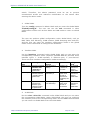
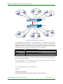
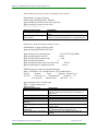
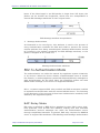
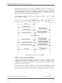
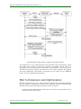
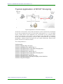
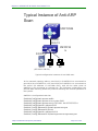
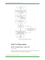
1
MyPower+S3026G-POE-AC Switch User Manual V1.0 Maipu Communication Technology Co., Ltd No. 16, Jiuxing Avenue Hi-tech Park Chengdu, Sichuan Province People’s Republic of China - 610041 Tel: (86) 28-85148850, 85148041 Fax: (86) 28-85148948, 85148139 URL: http:// www.maipu.com Email: [email protected] Maipu Confidential & Proprietary Information Page 1 of 472 MyPower+S3026G-POE-AC Switch User Manual V1.0 All rights reserved. Printed in the People’s Republic of China. No part of this document may be reproduced, transmitted, transcribed, stored in a retrieval system, or translated into any language or computer language, in any form or by any means, electronic, mechanical, magnetic, optical, chemical, manual or otherwise without the prior written consent of Maipu Communication Technology Co., Ltd. Maipu makes no representations or warranties with respect to this document contents and specifically disclaims any implied warranties of merchantability or fitness for any specific purpose. Further, Maipu reserves the right to revise this document and to make changes from time to time in its content without being obligated to notify any person of such revisions or changes. Maipu values and appreciates comments you may have concerning our products or this document. Please address comments to: Maipu Communication Technology Co., Ltd No. 16, Jiuxing Avenue Hi-tech Park Chengdu, Sichuan Province People’s Republic of China - 610041 Tel: (86) 28-85148850, 85148041 Fax: (86) 28-85148948, 85148139 URL: http:// www.maipu.com Email: [email protected] All other products or services mentioned herein may be registered trademarks, trademarks, or service marks of their respective manufacturers, companies, or organizations. Maipu Confidential & Proprietary Information Page 2 of 472 MyPower+S3026G-POE-AC Switch User Manual V1.0 Maipu Feedback Form Your opinion helps us improve the quality of our product documentation and offer better services. Please fax your comments and suggestions to (86) 28-85148948, 85148139 or email to [email protected]. Document Title MyPower+S3026G-POE-AC Switch User Manual V1.0 Product Version Evaluate this document Document Revision Number 1.0 Presentation: (Introductions, procedures, illustrations, completeness, arrangement, appearance) Good Fair Average Poor Accessibility: (Contents, index, headings, numbering) Good Fair Average Poor Editorial: (Language, vocabulary, readability, clarity, technical accuracy, content) Good Fair Average Poor Your suggestions to improve the document Please check suggestions to improve this document: Improve introduction Make more concise Improve Contents Add more step-by-step procedures/tutorials Improve arrangement Add more technical information Include images Make it less technical Add more detail Improve index If you wish to be contacted, complete the following: Name Company Postcode Address Telephone Maipu Confidential & Proprietary Information E-mail Page 3 of 472 MyPower+S3026G-POE-AC Switch User Manual V1.0 Contents Production Introduction ........................................................................ 12 Overview ............................................................................................................. 12 About the Product............................................................................................................... 12 Features ............................................................................................................................ 12 Main Features..................................................................................................................... 15 Technical Specifications ......................................................................................... 16 Physical Specifications ........................................................................................... 17 Product Appearance .............................................................................................. 17 Front Panel ........................................................................................................................ 17 Back Panel ......................................................................................................................... 17 LED ................................................................................................................................... 18 Hardware Installation ........................................................................... 19 Tools & Utilities................................................................................................................... 23 Setup Configuration............................................................................... 27 Setup Configuration .............................................................................................. 27 Setup Main Menu.................................................................................................. 27 Setup Sub Menu ................................................................................................... 28 Configuring Switch Hostname .............................................................................................. 28 Configure Vlan1 Interface.................................................................................................... 28 Configure Telnet Server ...................................................................................................... 29 Configure Web Server ......................................................................................................... 30 Configure SNMP ................................................................................................................. 30 Exit Setup Configuration Mode ............................................................................................. 32 Switch Management .............................................................................. 33 Management Modes.............................................................................................. 33 Out-band Management ....................................................................................................... 33 In-band Management ......................................................................................................... 37 Management Interfaces ........................................................................................ 43 CLI .................................................................................................................................... 43 Web Interface .................................................................................................................... 49 Basic Configuration of Switch................................................................ 52 Basic Configuration Commands.............................................................................. 52 clock set ............................................................................................................................ 52 Maipu Confidential & Proprietary Information Page 4 of 472 MyPower+S3026G-POE-AC Switch User Manual V1.0 config ................................................................................................................................ 53 exec timeout ...................................................................................................................... 53 exit.................................................................................................................................... 53 help................................................................................................................................... 54 ip host ............................................................................................................................... 54 ip http server ..................................................................................................................... 54 hostname .......................................................................................................................... 55 reload ................................................................................................................................ 55 set default.......................................................................................................................... 56 setup ................................................................................................................................. 56 language............................................................................................................................ 57 web-user ........................................................................................................................... 57 write.................................................................................................................................. 58 show cpu usage.................................................................................................................. 58 show tech-support.............................................................................................................. 58 vendorcontact .................................................................................................................... 59 vendorlocation.................................................................................................................... 59 web-language .................................................................................................................... 59 Maintaining and Debugging Commands .................................................................. 60 Ping................................................................................................................................... 60 Telnet ................................................................................................................................ 61 SSH................................................................................................................................... 66 Traceroute ......................................................................................................................... 71 Show................................................................................................................................. 72 Debug ............................................................................................................................... 79 Configure Switch IP Address .................................................................................. 79 Switch IP Address Configuration Task List ............................................................................. 80 Commands for Configuring Switch IP Address....................................................................... 81 SNMP Configuration .............................................................................................. 83 Introduction to SNMP .......................................................................................................... 83 Introduction to MIB............................................................................................................. 84 Introduction to RMON ......................................................................................................... 85 SNMP Configuration ............................................................................................................ 85 Typical SNMP Configuration Instance.................................................................................... 94 SNMP Troubleshooting ........................................................................................................ 95 Switch Upgrade .................................................................................................... 99 BootROM Upgrade .............................................................................................................. 99 FTP/TFTP Upgrade ............................................................................................................ 101 System Log........................................................................................................ 117 Introduction to System Log ............................................................................................... 117 System Log Configuration ................................................................................................. 119 System Log Configuration Instance .................................................................................... 125 Maipu Confidential & Proprietary Information Page 5 of 472 MyPower+S3026G-POE-AC Switch User Manual V1.0 System Log Troubleshooting ............................................................................................. 125 Configuration Classification .................................................................................. 128 Introduction to Configuration Classification ......................................................................... 128 Configure Classified Configuration ...................................................................................... 128 Port Isolation...................................................................................................... 130 Introduction to Port Isolation ............................................................................................. 130 Port Isolation Configuration ............................................................................................... 131 Cluster Network Management............................................................. 133 Introduction to Cluster Network Management ....................................................... 133 Basic Configuration of Cluster Network Management ............................................. 134 Cluster Network Management Configuration Task List.......................................................... 134 Cluster Configuration Commands....................................................................................... 136 Cluster Configuration Instance ............................................................................. 143 Cluster Troubleshooting....................................................................................... 144 Cluster Monitoring and Debugging Commands .................................................................... 144 Cluster Troubleshooting .................................................................................................... 147 Port Configuration ............................................................................... 149 Introduction to Port............................................................................................. 149 Port Configuration............................................................................................... 150 Ethernet Port Configuration ............................................................................................... 150 VLAN Interface Configuration............................................................................................. 158 Port Mirroring Configuration............................................................................................... 160 Port Configuration Instance ................................................................................. 164 Port Troubleshooting ........................................................................................... 165 Monitoring and Debugging Commands ............................................................................... 165 MAC Address Table .............................................................................. 170 Introduction to MAC Address Table....................................................................... 170 Obtain MAC Table ............................................................................................................. 170 Forward or Filter ............................................................................................................... 172 MAC Address Table Configuration......................................................................... 173 mac-address-table aging-time ........................................................................................... 173 mac-address-table............................................................................................................ 174 mac-address-table blackhole ............................................................................................. 174 clear mac-address-table dynamic....................................................................................... 175 Typical Configuration Instance ............................................................................. 176 MAC Table Troubleshooting ................................................................................. 177 Monitoring and Bugging Commands................................................................................... 177 Troubleshooting................................................................................................................ 177 MAC Address Function Extension.......................................................................... 178 MAC Address Binding ........................................................................................................ 178 VLAN Configuration ............................................................................. 186 Maipu Confidential & Proprietary Information Page 6 of 472 MyPower+S3026G-POE-AC Switch User Manual V1.0 Introduction to VLAN........................................................................................... 186 VLAN Configuration............................................................................................. 187 VLAN Configuration Task List ............................................................................................. 187 VLAN Configuration Commands ......................................................................................... 189 VLAN Typical Application ................................................................................................... 194 Dot1q-tunnel Configuration ................................................................................. 196 Introduction to Dot1q-tunnel ............................................................................................. 196 Dot1q-tunnel Configuration Task List.................................................................................. 198 Dot1q-tunnel Configuration Commands.............................................................................. 198 Typical Dot1q-tunnel Application ........................................................................................ 200 Dot1q-tunnel Troubleshooting ........................................................................................... 201 Protocol VLAN Configuration ................................................................................ 202 Introduction to Protocol VLAN ............................................................................................ 202 Protocol VLAN Configuration Task List................................................................................. 202 Protocol VLAN Configuration Commands............................................................................. 203 Protocol VLAN Troubleshooting ............................................................................ 205 VLAN Troubleshooting ......................................................................................... 205 Monitoring and Debugging Information .............................................................................. 205 MSTP Configuration ............................................................................. 207 Introduction to MSTP .......................................................................................... 207 MSTP Domain .................................................................................................................. 207 Port Roles ........................................................................................................................ 209 MSTP Load Balance........................................................................................................... 209 MSTP Configuration ............................................................................................ 209 MSTP Configuration Task List ............................................................................................. 209 MSTP Configuration Commands ......................................................................................... 212 MSTP Instances .................................................................................................. 225 MSTP Troubleshooting......................................................................................... 230 Monitoring and Debugging Commands ............................................................................... 230 MSTP Troubleshooting....................................................................................................... 234 IGMP Snooping Configuration ............................................................. 235 Introduction to IGMP Snooping ............................................................................ 235 IGMP Snooping Configuration .............................................................................. 235 IGMP Snooping Confgiuration Task List............................................................................... 235 IGMP Snooping Configuration Commands........................................................................... 237 IGMP Snooping Instance ..................................................................................... 244 IGMP Snooping Troubleshooting .......................................................................... 247 IGMP Snooping Monitoring and Debuging Commands ......................................................... 247 IGMP Snooping Troubleshooting ........................................................................................ 249 Multicast VLAN Configuration.............................................................. 250 Introduction to Multicast VLAN ............................................................................. 250 Maipu Confidential & Proprietary Information Page 7 of 472 MyPower+S3026G-POE-AC Switch User Manual V1.0 Multicast VLAN Configuration ............................................................................... 250 Multicast VLAN Configuration Task List ............................................................................... 250 Multicast VLAN Configuration Commands ........................................................................... 251 Multicast VLAN Instance ...................................................................................... 252 DCSCM Configuration........................................................................... 254 Introduction to DCSCM........................................................................................ 254 DCSCM Configuration.......................................................................................... 254 DCSCM Configuration Task List .......................................................................................... 254 DCSCM Configuration Commands ...................................................................................... 257 Typical DCSCM Instance...................................................................................... 263 DCSCM Troubleshooting ...................................................................................... 264 DCSCM Monitoring and Debugging Commands ................................................................... 264 DCSCM Troubleshooting.................................................................................................... 267 802.1x Configuration ........................................................................... 268 Introduction to 802.1x ........................................................................................ 268 802.1x Authentication Architecture .................................................................................... 268 802.1x Work Mechanism................................................................................................... 271 EAPOL Message Encapsulation........................................................................................... 271 EAP Attribute Encapsulation............................................................................................... 273 802.1x Authentication Mode .............................................................................................. 274 802.1x Extension and Optimization .................................................................................... 279 VLAN Allocation Features................................................................................................... 280 802.1x Configuration .......................................................................................... 282 802.1x Configuration Task List........................................................................................... 282 802.1x Configuration Commands....................................................................................... 285 802.1x Application Instance................................................................................. 301 802.1x Troubleshooting....................................................................................... 302 802.1x Debugging and Monitoring Commands .................................................................... 302 802.1x Troubleshooting .................................................................................................... 310 ACL Configuration ................................................................................ 311 Introduction to ACL ............................................................................................. 311 Access-list .......................................................................................................... 311 Access-group ................................................................................................................... 311 Access-list Action and Global Default Action ........................................................................ 312 ACL Configuration ............................................................................................... 312 ACL Configuration Task List ............................................................................................... 312 ACL Configuration Commands ........................................................................................... 321 ACL Instances .................................................................................................... 337 ACL Troubleshooting ........................................................................................... 340 ACL Debugging and Monitoring Commands ........................................................................ 340 ACL Troubleshooting ......................................................................................................... 342 Maipu Confidential & Proprietary Information Page 8 of 472 MyPower+S3026G-POE-AC Switch User Manual V1.0 AM Configuration ................................................................................. 344 Introduction to AM .............................................................................................. 344 AM Pool ............................................................................................................. 344 AM Configuration ................................................................................................ 344 AM Configuration Task List ................................................................................................ 344 AM Configuration Commands ............................................................................................ 345 AM Instances ..................................................................................................... 348 AM Troubleshooting ............................................................................................ 349 AM Debugging and Monitoring Commands ......................................................................... 349 AM Troubleshooting .......................................................................................................... 350 Port Channel Configuration ................................................................. 351 Introduction to Port Channel ................................................................................ 351 Port Channel Configuration .................................................................................. 352 Port Channel Configuration Task List .................................................................................. 352 Port Channel Configuration Commands .............................................................................. 353 Port Channel Instance ......................................................................................... 355 Port Channel Troubleshooting .............................................................................. 357 Monitoring and Debugging Commands ............................................................................... 357 Port Channel Troubleshooting ............................................................................................ 361 DHCP Configuration ............................................................................. 363 Introduction to DHCP .......................................................................................... 363 Configure DHCP Server ....................................................................................... 364 DHCP Server Configuration Task List .................................................................................. 364 DHCP Configuration Commands......................................................................................... 366 DHCP Server Configuration Instance .................................................................................. 377 DHCP Troubleshooting ........................................................................................ 378 Monitoring and Debugging Commands ............................................................................... 378 DHCP Troubleshooting ...................................................................................................... 382 DHCP Snooping Configuration ............................................................. 384 Introduction to DHCP Snooping............................................................................ 384 DHCP Snooping Configuration .............................................................................. 385 DHCP Snooping Configuration Task list ............................................................................... 385 DHCP Snooping Configuration Commands .......................................................................... 387 Typical Application of DHCP Snooping................................................................................. 394 DHCP Snooping Troubleshooting .......................................................................... 395 Monitoring and Debugging Information .............................................................................. 395 DHCP Snooping Troubleshooting........................................................................................ 398 ARP Guard Configuration..................................................................... 401 Introduction to ARP Guard ................................................................................... 401 ARP Guard Configuration ..................................................................................... 402 Maipu Confidential & Proprietary Information Page 9 of 472 MyPower+S3026G-POE-AC Switch User Manual V1.0 ARP Guard Configuration Task List ..................................................................................... 402 ARP Guard Configuration Command................................................................................... 402 Anti-ARP Scanning............................................................................... 404 Introduction to Anti-ARP Scanning ....................................................................... 404 Anti-ARP Scanning Configuration.......................................................................... 405 Anti-ARP Scanning Configuration Task List.......................................................................... 405 Anti-ARP Scanning Configuration Commands ...................................................................... 406 Anti-ARP Scanning Troubleshooting ...................................................................... 411 Monitoring and Debugging Information .............................................................................. 411 Typical Instance of Anti-ARP Scan ........................................................................ 414 Port Loopback Detection Function ...................................................... 416 Introduction to Port Loopback Detection Function .................................................. 416 Port Loopback Detection Function Configuration .................................................... 417 Configuration Task List of Port Loopback Detection Function................................................. 417 Commands for Configuring Port Loopback Detection Function .............................................. 418 Typical Instance of Port Loopback Detection.......................................................... 420 Port Loopback Detection Troubleshooting.............................................................. 421 Debugging and Monitoring Commands ............................................................................... 421 Port Loopback Detection Troubleshooting ........................................................................... 422 SNTP Configuration ............................................................................. 423 Introduction to SNTP........................................................................................... 423 SNTP Configuration............................................................................................. 424 SNTP Configuration Task List ............................................................................................. 424 SNTP Configuration Commands ......................................................................................... 424 SNTP Troubleshooting ......................................................................................... 426 SNTP Debugging and Monitoring Commands ...................................................................... 426 SNTP Typical Configuration Instance .................................................................... 427 QoS Configuration................................................................................ 428 Introduction to QoS ............................................................................................ 428 QoS Terms....................................................................................................................... 428 QoS Implementation......................................................................................................... 429 Basic QoS Model............................................................................................................... 430 QoS Configuration .............................................................................................. 433 QoS Configuration Task List............................................................................................... 433 QoS Configuration Commands ........................................................................................... 436 QoS Instances .................................................................................................... 446 QoS Troubleshooting........................................................................................... 448 QoS Debugging and Monitoring Commands ........................................................................ 448 QoS Troubleshooting ........................................................................................................ 453 L3 Configuration .................................................................................. 454 Maipu Confidential & Proprietary Information Page 10 of 472 MyPower+S3026G-POE-AC Switch User Manual V1.0 L3 Interface ....................................................................................................... 454 Introduction to L3 Interface ............................................................................................... 454 L3 Interface Configuration ................................................................................................. 454 ARP ................................................................................................................... 459 Introduction to ARP........................................................................................................... 459 ARP Configuration............................................................................................................. 459 POE Configuration ............................................................................... 462 Introduction to POE ............................................................................................ 462 POE Configuration............................................................................................... 462 POE Configuration Task List ............................................................................................... 462 POE Configuration Commands ........................................................................................... 464 POE Typical Application ....................................................................................... 467 POE Troubleshooting ........................................................................................... 469 Monitoring and Debugging Information .............................................................................. 469 POE Troubleshooting......................................................................................................... 471 Maipu Confidential & Proprietary Information Page 11 of 472 MyPower+S3026G-POE-AC Switch User Manual V1.0 Production Introduction Overview MyPower S3026G-POE-AC switch About the Product MyPower S3026G-POE-AC Switch can not only be utilized in large-scale enterprise network, campus network and MAN as access equipment, but also can meet the demand of medium-scale office network. The switch has unique network access functions and flexible network management function, including MAC binding/filtering, limiting the number of MAC addresses, IEEE802.1Q VLAN, PVLAN, IEEE802.1x access authentication, QoS, ACL, bandwidth control, IEEE802.3ad TRUNK, IGMP Snooping, broadcast storm suppression, IEEE802.1d/w spanning tree, port mirroring and so on. Features MAC address control Besides the standard dynamic learning of MAC address, MyPower S3026GPOE-AC switch also supports several MAC managing methods based on the MAC address list. For secure access, the MAC address binding function can restrict the MAC addresses of access devices connected to a port. The MAC address filtering function can block the invalid access devices by filtering source and destination MAC addresses. VLAN Configuration Maipu Confidential & Proprietary Information Page 12 of 472 MyPower+S3026G-POE-AC Switch User Manual V1.0 MyPower S3026G-POE-AC switch supports standard IEEE802.1Q VLAN, port-protection VLAN and PVLAN. IEEE802.1 Q VLAN can divide ports into as many as 4094 VLAN groups. It can also realize multi-switch VLAN division via IEEE802.1 Q VLAN tags, and thus manage to control broadcast traffic, guarantee the security and performance of the network at the same time. PVLAN function can divide ports into isolated ports and community ports. It can isolate or connect ports according to the network applications demands. QoS MyPower S3026G-POE-AC switch supports rich QoS policies, by providing 4 precedence queues on each port and by supporting WRR/SP scheduling. This switch also supports port trust, by sorting its traffic according to port, VLAN, DSCP, IP precedence and ACL table. Besides, it can modify the DSCP and IP precedence of the packets and specify different bandwidths for voice/data/video to provide different QoS. ACL MyPower S3026G-POE-AC switch supports the complete ACL policy. ACL is a mechanism realized by switches to filter IP data. By allowing or denying specific data packets entering/leaving the network, a switch can control the network access and effectively guarantee the secure operation of the network. The switch supports IP-based, MAC-based and MAC-IP-based ingress filtering, it can also filter data based on the information of source/destination IP addresses, source/destination MAC addresses, IP protocol type, TCP/UDP port, IP precedence, time range and ToS. IEEE802.1x access authentication MyPower S3026G-POE-AC switch supports both port-based IEEE802.1x authentication mode and MAC-based IEEE802.1x authentication mode. It can set the upper threshold of authenticated access users per port, realize dynamic secure authentication mode based on MAC address, and bind the MAC address of an authenticated device to a port. With the IEEE802.1x authentication modes cooperating with the authenticating&accounting products, a complete set of IEEE802.1x AAA solutions can be provided, meeting the requirements of access, authenticating and accounting, and ensuring the network security and operatability. Bandwidth Control (Port Speed Limit) MyPower S3026G-POE-AC switch can control the upstream/downstream bandwidth and provide different access bandwidth for users at different levels. Each port can set its own bandwidth rate according to the requirements for controlling access bandwidth. Maipu Confidential & Proprietary Information Page 13 of 472 MyPower+S3026G-POE-AC Switch User Manual V1.0 Port trunk MyPower S3026G-POE-AC switch supports IEEE802.3ad standard TRUNK and can realize link redundancy and traffic load balance. IGMP Snooping MyPower S3026G-POE-AC switch supports multicast applications based on the IGMP Snooping mechanism, and thus realizes all kinds of multicast services, decreases the network traffic and meets the requirements of multicast services like multimedia playing, remote teaching and entertainment. Multicast VLAN MyPower S3026G-POE-AC switch adds ports of the switch into a multicast VLAN by configuring the multicast VLAN. With the IGMP Snooping enabled, users of different VLANs can use the same multicast VLAN, which restricts the multicast flow within only one multicast VLAN, and thus save the bandwidth effectively. Broadcast Storm Suppression MyPower S3026G-POE-AC switch supports broadcast storm suppression, and thus can effectively control broadcast storm, decrease useless occupation of the bandwidth, and increase the overall network performance. Spanning Tree MyPower S3026G-POE-AC switch supports IEEE802.1d spanning tree, IEEE802.1w rapid spanning tree, and IEEE802.1s spanning tree. The spanning tree can effectively avoid loopback, and at the same time, create a redundant backup for the link. Port mirroring MyPower S3026G-POE-AC supports port mirroring, which can mirror the inbound/outbound traffic of one or more ports to another one, in order to detect related data information. This function can be used to debug network faults and monitor the network traffic. DHCP Server and Client Maipu Confidential & Proprietary Information Page 14 of 472 MyPower+S3026G-POE-AC Switch User Manual V1.0 MyPower S3026G-POE-AC supports DHCP server, which can dynamically allocate IP addresses for hosts, and bind MAC with IP by designating a specified IP for a specified MAC. RADIUS MyPower S3026G-POE-AC supports RADIUS (Remote Authentication Dial in User Service) authentication negotiation. RADIUS allows users to authenticate identification via IEEE802.1x protocol. Complete Network Management MyPower S3026G-POE-AC supports out-of-band and in-band management via Console, Telnet, Web and SNMP. The Console and Telnet management supports standard CLI (Command Line Interface), which makes the operation easier and faster; it also provides bilingual instructions in Chinese and English. Web management provides a remote GUI management interface, making management more direct and convenient, while enabling immediate check of working state and real-time configuration management. SNMP management is in accordance with V1, V2C and V3 standard versions. It supports Ether-Like MIB, Bridge MIB and MIB II, as well as standard management information libraries, such as RMON 1/2/3/9 MIB. It supports SSH protocol, which ensures the security of the configuration management in the switch. Besides, it provides a unique function to manage and set the IP of workstations, enabling the switch to automatically filter invalid remote network management access, and thus guarantee the efficiency, security and consistency of remote network management access. Main Features Applying Store-and-Forward transmission All of the RJ-45 ports support MDI/MDI-X self-adaptation, can be conveniently cascade connected to other switcher using straightthrough twisted pair Providing Console port Allowing users to check the working state and statistic information of ports Can be rebooted locally and remotely to reset the switch to the default configuration Can update the firmware via TFTP/FTP Maipu Confidential & Proprietary Information switch mode to ensure block-free Page 15 of 472 MyPower+S3026G-POE-AC Switch User Manual V1.0 Can be fixed in a standard 19-inch frame Technical Specifications Protocols and Standards IEEE802.3 10BASE-T Ethernet IEEE802.3u 100BASE-TX/FX fast Ethernet IEEE802.3x traffic control IEEE802.1x network access control IEEE802.1d/ s spanning tree IEEE802.1p priority control IEEE802.1q VLAN IEEE802.3ad link aggregation TFTP/FTP DHCP BootP Telnet IP/UDP/TCP/ICMP HTTP SNMP V1/V2C/V3 Management Protocols and Methods CLI command line Supports SNMP V1/V2C Supports Web and Telnet management RFC1757 RMON (1, 2, 3, 9) MIB RFC1213 MIB II RFC1493 Bridge MIB Maipu Confidential & Proprietary Information Page 16 of 472 MyPower+S3026G-POE-AC Switch User Manual V1.0 RFC1643 Ether-Like MIB Private MIB Physical Specifications MyPower S3026G-POE-AC Weight 4.13KG Dimension (mm) Operation temperature Storage Temperature Relative humidity AC Power Input 440× 171.2× 43 Power Consumption Max. 30W Mean Time Before Failure 80,000 hours 0C-45C -40C~70C 10%~90%, with no condensation 100~240VAC, 50~60Hz 45W (system power consumptio) 180W (PoE power consumption for outside) 225W (max. power consumption during full load) Product Appearance Front Panel The front panel of MyPower S3026G-POE-AC switch: Back Panel The back panel of MyPower S3026G-POE-AC switch: Maipu Confidential & Proprietary Information Page 17 of 472 MyPower+S3026G-POE-AC Switch User Manual V1.0 LED The LED indicators of MyPower S3026G-POE-AC switch include System, Link/Act and 1000M indicators. The following figure demonstrates the LED indicators of MyPower S3026G-POE-AC: The LED indicators of MyPower S3026G-POE-AC The LED indicators of of MyPower S3026G-POE-AC LED Link/ACT 1000M LED State Blinking Off Amber Description The port is successfully linked; It is receiving/sending data The port is down The port is providing power. Green The port is linked. On The corresponding G interface is in the connected state (1000M) The corresponding G interface is in the connected state (100M) or down state. The power is connected. The power is not connected. Off PWR On (green) Off Maipu Confidential & Proprietary Information Page 18 of 472 MyPower+S3026G-POE-AC Switch User Manual V1.0 Hardware Installation Precautions To ensure your security and the normal operation of the MyPower S3026G-POE-AC switch, please carefully read the following instructions and notices while installing and using the switch. Installation Environment A clean environment is necessary for normal operation of the switch. No dust is allowed. Otherwise, the switch may be damaged by electrostatic adherence. The switch does not have the switch. During the installation, you need to out-connect the circuit control switch, so as to cut off the power when the emergency happens. The switch requires a non-condensing environment with a temperature between 0 to 45 °C and humidity from 10% to 90%. The switch must be kept in a dry and cool place with sufficient space around it for air circulation. The switch requires a power input ranging from 100 to 240 VAC (50 ~ 60Hz). Make sure that the switch is safely grounded, which can prevent electrostatic damage to the device and potential dangers to people. Avoid direct exposure to sunlight, and keep the switch away from heat sources and strong electromagnetic interference sources. The switch must be stably mounted to a standard 19‟‟ rack or placed on a desktop. D ust - Free En vi ron ment Dust is harmful for the operation of the switch. Dust causes electrostatic absorption, which makes the poor contact of metal pieces. Electrostatic absorption appears especially when the temperature and humidity are lower, which affects the device life and causes communication fault. The Maipu Confidential & Proprietary Information Page 19 of 472 MyPower+S3026G-POE-AC Switch User Manual V1.0 recommended values of dust content and particle diameter of the switch‟s working environment are listed below: Maximum diameter (μm) Max Diameter (particles /m3) 0.5 1.4× 10⁵ 1 7× 10⁵ 3 2.4× 10⁵ 5 1.3× 10⁵ Other than dust, the content of salt, acid and sulfide in the air should also be restricted to meet the requirements of switch‟s working environment. Such harmful gases will aggravate metal corrosion and the aging of some parts. The working environment should be free of harmful gases, like SO2, H2S, NO2, NH3 and Cl2, and etc. The table below demonstrates the recommended threshold of those gases: Gas SO2 H2S NO2 NH3 Cl2 3 Average (mg/m ) 0.2 0.006 0.04 0.05 0.01 3 Maximum value (mg/m ) 1.5 0.03 0.15 0.15 0.3 Te mperature and Hu midi t y For a good air circulation after the switch being installed, it is recommended to keep the switch rack in a room with a stable temperature and humidity. Please use an air-conditioner to cool it up in summer and a heating system in winter. If the humidity in the equipment room is too high for long time, it causes the poor insulation and even electricity leak of insulation materials easily. Sometimes, the mechanical performances of materials change and the metal parts are corroded easily, too. If the relative humidity is too low, insulation pads shrink, which causes the fastened screws loose. Meanwhile, in dry environment, static electricity appears easily, which harms the circuits on the switch. If the temperature is too high, the reliability of the switch reduces greatly. The long-time high temperature affects the life and speeds up the aging of insulation materials. The recommended working temperature and humidity are listed in the following table: Temperature 0~50℃ Relevant humidity 10~90% Note: The working environment temperature and humidity of the switch should be measured at 1.5m above the floor and 0.4m in front of the rack, without front or back protective panel on the rack. Po wer The switch uses module switching power. The parameters of input AC power are as follows: Maipu Confidential & Proprietary Information Page 20 of 472 MyPower+S3026G-POE-AC Switch User Manual V1.0 Input Voltage: 100-240VAC Frequency: 50-60Hz Total power consumption: ≤225W (maximum power consumption with full load) Before powering on the switch, please make sure a proper grounding of the power supply system and the stability of the input power. Use a voltage adapter device if necessary. A fuse or a circuit-breaker no greater than 240 V, 10 A is required to prevent short circuits. A UPS is recommended to provide a more reliable power supply. Warning An improper grounding of power supply system, dramatic electric fluctuations or pulses can result in abnormal operation and even hardware damage! Anti -static Static electric may damage the switch circuits, or the entire device. To prevent the damages of static electricity, please ensure a good grounding; keep the environment dust-free, and maintain a proper temperature and humidity. Operators should wear antistatic uniforms, straps, or gloves. Anti -interfe rence Various interference sources, no matter from the switch or other devices, or from interior or exterior, affect the switch through capacitance coupling, inductance coupling, electromagnetic radiation, public impedance (including grounding system) and lead (such as power lines, signal lines and output lines). To avoid the interferences, please follow the instructions below: Take anti-electric network interference for power system. The switch working place had better not be used with the grounding settings of power devices or anti-lightening grounding settings, and the distance between them had better be as long as possible. Be away from the strong power radio transmitters, radar transmitter, and high frequency high-current equipments; Take electromagnetic shielding methods when necessary. Maipu Confidential & Proprietary Information Page 21 of 472 MyPower+S3026G-POE-AC Switch User Manual V1.0 R ack Configu rat i on The switch size fits the standard 19‟‟ rack. Pay attention to the following instructions to ensure a good ventilation and air circulation: All devices on the rack generate heat during their operation. Therefore vents and fans are required for an enclosed rack. Keep devices at a certain distance from each other to ensure a good ventilation and air circulation. On the open rack, do not block the vents on both sides of the switch. After the switch is installed, check the state of the switch. Note: Put the switch on a stable and clean desktop as a substitute of a standard 19‟‟ rack, leaving a proper space around the switch for ventilation. And don‟t place anything on top of it. Installation Instructions Read related chapters in this manual carefully or participate in concerning technology training before the installation. Make sure all materials, tools and other items required by the installation are prepared, as well as a proper site for installation and debugging. During the installation, it is required to use the brackets and screws provided in the accessory kit, and proper tools to ensure stability and reliability. Users should always wear antistatic uniforms and ESD wrist straps to prevent damaging the switch, and should only use and make standard cables and connecters. Be cautious to potential dangers during the installation, and make protective preparations to avoid accidents. Clean the site after the installation. Please ensure the switch is well grounded before powering it on. Users should also maintain the switch regularly to extend its lifespan. Security Warnings Do not stare directly at the fiber port during operation to prevent eye damage caused by the laser transceiver in the SFP optical module of the switch. Do not attempt to conduct any operation which may cause physical injuries, accidents or damage the switch. Do not install, remove, or disassemble switch and modules with power on to avoid injuring yourself or damaging the equipment. Maipu Confidential & Proprietary Information Page 22 of 472 MyPower+S3026G-POE-AC Switch User Manual V1.0 Do not open the switch without permission. Please resort to the manufacturer for help if any problem occurs, to prevent physical injuries and device damages. No contact between metals and the working power is allowed, and do not drop metals into the switch, to prevent short-circuit and device damages. Do not touch the power plug and power socket, to prevent electric shock. Do not place the tinder near the switch, to prevent fire. Do not debug the switch alone in a dangerous situation, to prevent accidents. Use standard power sockets which have overload and leakage protection, to prevent accidents. Check the circuits, installation and the working environment for potential dangers, and maintain them regularly, for the sake of security. Place the emergency power switch in the working site, so that the power can be cut off immediately if any accident occurs. Note: The potential dangers include: electric leakage in the power, the ignition of the power, broken electric cables or lines, bad grounding, electric overload, short-circuit and etc. In cases of accidents like electric shock, fire or shortcircuit, please cut off the power immediately and call the police. Please help the victims after confirming the security and provide first aid according to their situations. Call professional medical organizations for help in time. Installation Preparations Check Packing List Open the package and check whether the device and the accessories are complete according to the packing list. Tools & Utilities The required tools and utilities Maipu Confidential & Proprietary Information Cross screwdrivers Flat-blade screwdriver wire clamp Antistatic uniform Page 23 of 472 MyPower+S3026G-POE-AC Switch User Manual V1.0 ESD wrist strap Antistatic glove Console cable and commutator Connecting cable Standard Twisted-pair RJ-45 pin Hardware Installation Mount Switch to Rack MyPower S3026G-POE-AC can be mounted onto a standard 19‟‟ rack. Perform the following steps to install the switch. Mount MyPower S3026G-POE-AC to the rack 1. Attach the brackets on both sides of the switch with screws provided in the accessory kit. 2. Put the bracket-mounted switch onto a standard 19‟‟ rack. Fasten it at a proper location with the screws provided, leaving enough space around the switch for good air circulation. Note: The brackets are used to fix the switch on the rack rather than bearing its weight, so it is recommended to place a rack shelf under the switch. Do not place anything on top of the switch or block the vents, to prevent device damages and abnormal operation. Maipu Confidential & Proprietary Information Page 24 of 472 MyPower+S3026G-POE-AC Switch User Manual V1.0 Console Cable Connection MyPower S3026G-POE-AC provides a DB9 asynchronous serial console port. Perform the following steps to connect the Console port: Connecting Console port to MyPower S3026G-POE-AC 1. Insert the connector of the Console cable to the Console port of the switch. 2. Connect the other end of the console to a character terminal (usually a computer). 3. After the switch and the character terminal are powered on, you can create the configuration management connection with the switch through the character terminal. Note: Please use the provided console cable and the console adaptor of the switch. Don‟t insert the console cable to other ports or insert other cables in the Console port, to prevent damaging the cable and the port. Power Cable Connection The power of the MyPower S3026G-POE-AC switch is 100~240VAC, 50~60Hz, allowing a certain extent of voltage fluctuation. Perform the following steps to connect the power cable. Maipu Confidential & Proprietary Information Page 25 of 472 MyPower+S3026G-POE-AC Switch User Manual V1.0 Connecting power cable to MyPower S3026G-POE-AC 1. Insert one end of the provided power cable into the power slot at the back of the switch. Insert the other end of the power cable into power socket with overloading/leakage protection. 2. Check whether the power indicator in the front panel is on. The switch is self-adjustable according to the input voltage. Therefore, if the input voltage complies with the specified voltage range, the switch can operate normally and extra debugging is not required. 3. The switch will implement self-testing when powered on. Note: The input voltage must comply with the power specification of the switch. Otherwise, the switch may be damaged or work improperly. If the power indicator is off or the self-check is abnormal after the switch is powered on, contact Maipu customer service center. Do not disassemble the switch. Maipu Confidential & Proprietary Information Page 26 of 472 MyPower+S3026G-POE-AC Switch User Manual V1.0 Setup Configuration Setup configuration refers to the initial operation to the switch after the user purchases the switch. For first-time users of the MyPower S3026GPOE-AC switch, this chapter provides a very practical instruction. When using the Command Line Interface (CLI), the user can type setup under admin mode to enter the Setup configuration interface. Setup configuration is done via menu selections, in which switch hostname, Vlan1 interface, Telnet service, Web service, and SNMP, can be configured. Setup Configuration Setup is configured via the menu. In Setup configuration mode, you can configure the host name, interface VLan1, Telnet service, Web service, and SNMP of the switch. Setup Main Menu Before entry into the main menu, the following screen is displayed to prompt the user to select a preferred interface language. English users should choose „0‟ to enter the English interface, while Chinese users can choose „1‟ to view the interface in Chinese. Please select language [0]:English [1]: Chinese Selection(0|1)[0]: The main Setup configuration menu is listed below: Configure menu [0]:Config hostname [1]:Config interface-Vlan1 [2]:Config telenet-server [3]:Config web-server [4]:Config SNMP [5]:Exit setup configuration without saving Maipu Confidential & Proprietary Information Page 27 of 472 MyPower+S3026G-POE-AC Switch User Manual V1.0 [6]:Exit setup configuration after saving Selection number: Setup Sub Menu Configuring Switch Hostname Select „0‟ in the Setup main menu and press Enter, and the following screen appears: Please input the host name[switch]: Note: the hostname entered should be less than 30 characters. If the user presses Enter without input, the hostname is switch by default. Configure Vlan1 Interface Select „1‟ in the Setup main menu and press Enter to start configuring the Vlan1 interface. Config Interface-Vlan1 [0]: Config interface-Vlan1 IP address [1]: Config interface-Vlan1 status [2]: Exit Selection number: Select „0‟ in the Vlan1 interface configuration menu and press Enter, the following screen appears: Please input interface-Vlan1 IP address (A.B.C.D): When the user enters valid IP address for Vlan1 interface and presses Enter, the following screen appears: Please input interface-Vlan1 mask [255.255.255.0]: By default, the system sets the mask of VLAN1 interface as 255.255.255.0. The user can configure the IP address and mask according to the actual network environment. After the configuration, return to the VLAN1 interface configuration menu. Select „1‟ in the Vlan1 interface configuration menu, press Enter, and the following screen appears: Open interface-Vlan1 for remote configuration ? (y/n) [y]: Maipu Confidential & Proprietary Information Page 28 of 472 MyPower+S3026G-POE-AC Switch User Manual V1.0 When powering on for the first time, the Vlan1 interface (that is CPU port) is in the closed state and the user needs to enable the Vlan1 interface of the switch via the command. Pressing Enter means to enable the VLan1 interface of the switch. If selecting „2‟ in the Vlan1 interface configuration menu, return to the Setup main menu. Configure Telnet Server Select „2‟ in the Setup main menu, and press Enter to start configuring the Telnet server. The follow appears: Configure telnet server [0]: Add telnet user [1]: Config telnet server status [2]: Exit Selection number: Select „0‟ in the Telnet server configuration menu, press Enter, and the following screen appears: Please input the new telnet user name : Note: The valid username length is 1 to 16 characters. When the user enters a valid username and presses Enter, the following screen appears. Please input the new telnet user password : Note: The valid length of the password is 1-8 characters. After configuring the user name and password, return to the menu of configuring the Telnet server. Select „1‟ in the Telnet server configuration menu, press Enter, and the following screen appears: Enable switch telnet-server or no?(y/n) [y]: To enable the Telnet service, input y or press Enter. If the user does not need to enable Telnet service, input n and press Enter. And then, return to the menu of configuring the Telnet server. If selecting „2‟ in the Telnet server configuration menu, return to the Setup main menu. Maipu Confidential & Proprietary Information Page 29 of 472 MyPower+S3026G-POE-AC Switch User Manual V1.0 Configure Web Server Select „3‟ in the Setup main menu, press Enter to start configuring the Web server, and the follow appears: Configure web server [0]: Add webuser [1]: Config web server status [2]: Exit Selection number: Select „0‟ in the Web server configuration menu, press Enter, and the following screen appears: Please input the new web user name : Note: the valid username length is 1 to 16 characters. When the user enters a valid username and presses Enter, the following screen appears Please input the new web user password : Note: The valid password length is 1 to 8 characters. After configuring the username and password, return to the Web server configuration menu. Select „1‟ in the Web server configuration menu, press Enter, and the following screen appears: Enable switch web-server or no?(y/n) [y]: To enable the Web service, input y or press Enter. If the user does not need to enable the web service, input n and press Enter. And then, return to the Telnet server configuration menu. If selecting „2‟ in the Telnet server configuration menu, return to the Setup main menu. Configure SNMP Select „4‟ in the Setup main menu and press Enter to start configuring SNMP, as follows: Configure SNMP [0]: Config SNMP-server read-write community string [1]: Config SNMP-server read-only community string [2]: Config traps-host and community string [3]: Config SNMP-server status [4]: Config SNMP traps status [5]: Add SNMP NMS security IP address Maipu Confidential & Proprietary Information Page 30 of 472 MyPower+S3026G-POE-AC Switch User Manual V1.0 [6]: Exit Selection number: Select „0‟ in SNMP configuration menu, press Enter, and the following screen appears: Please input the read-write access community string[private]: Note: The valid length for a read-write access community string is 1 to 255 characters. The default value is „private‟. After a valid read-write access community string is entered, press Enter and return to the SNMP configuration menu. Select „1‟ in the SNMP configuration menu, press Enter, and the following screen appears: Please input the read-only access community string[public]: Note: The valid length for a read-only access community string is 1 to 255 characters. The default value is „public‟. When a valid read-only access community string is entered, press Enter and return to the SNMP configuration menu. Select „2‟ in the SNMP configuration menu, press Enter, and the following screen appears: Please input traps-host IP address(A.B.C.D): When the user enters a valid IP address for Traps host, presses Enter, and the following appears: Please input traps community string[public]: Note: The valid length for a traps community string is 1 to 255 characters, and the default value is „public‟. When a valid communication community string is entered, press Enter and return to the SNMP configuration menu. Select „3‟ in the SNMP configuration menu, press Enter, and the following screen appears: Enable SNMP-server? (y/n) [y]: To enable the SNMP service, input y and press Enter or directly press Enter. If the user does not need to enable the SNMP service, input n and press Enter. And then, return to the SNMP configuration menu. Select „4‟ in the SNMP configuration menu, press Enter, and the following screen appears: Maipu Confidential & Proprietary Information Page 31 of 472 MyPower+S3026G-POE-AC Switch User Manual V1.0 Enable SNMP-traps ? (y/n) [y]: If the user needs the switch to send messages to Traps, input y and press Enter or directly press Enter. If the user does not need to send, input n and press Enter. And then return to the SNMP configuration menu. Select „5‟ in the SNMP configuration menu, press Enter, and the following screen appears: Please input the new NMS IP address(A.B.C.D): When a valid secure IP address for SNMP management workstation is entered, press Enter and return to the SNMP configuration menu. Select „6‟ in the SNMP configuration menu and return to the Setup main menu. Exit Setup Configuration Mode Select „5‟ in the Setup main menu to exit the Setup configuration mode without saving the configurations. Select „6‟ in the Setup main menu to exit the Setup configuration mode and save the configurations. For instance, if the user sets the IP address and enables the web service under the Setup configuration mode, the user can use the terminal to manage and configure the switch via the Telnet service after selecting “6” to exit the Setup main menu. When the user exits the Setup configuration mode, the CLI configuration interface appears. Configuration commands and syntaxes are described in detail in later chapters. Maipu Confidential & Proprietary Information Page 32 of 472 MyPower+S3026G-POE-AC Switch User Manual V1.0 Switch Management Management Modes After purchasing the switch, the user needs to configure the switch for network management. MyPower S3026G-POE-AC provides two management modes: in-band management and outband management. Out-band Management Out-band management is to manage the switch via the Console interface. Generally, the user adopts out-band management for the initial switch configuration, or when in-band management is not available. For instance, the user must assign an IP address to the switch via the Console interface to be able to access the switch via Telnet. The procedures for managing the switch via the Console interface are listed below: Step 1: set up the environment: Outband management configuration environment of MyPower S3026GPOE-AC As shown in above, the serial port (RS-232) is connected to the switch with the serial cable provided. The table below lists all the devices used in the connection. Maipu Confidential & Proprietary Information Page 33 of 472 MyPower+S3026G-POE-AC Switch User Manual V1.0 Device Name PC Serial port cable MyPower S3026G-POEAC Description Has functional keyboard and RS-232, with terminal emulator installed, such as HyperTerminal included in Windows 9x/NT/2000/XP. One end is connected to the RS-232 serial port, and the other end to the Console port. Functional Console port required. Step 2: Enter the HyperTerminal Open the HyperTerminal included in Windows after the connection is established. The example below is based on the HyperTerminal included in Windows XP. Click Start > HyperTerminal. All Programs > Accessories > Communication Open Hyper Terminal Type a name for opening HyperTerminal, such as “Switch”. Maipu Confidential & Proprietary Information Page 34 of 472 > MyPower+S3026G-POE-AC Switch User Manual V1.0 Open HyperTerminal In the “Connect using” drop-list, select the RS-232 serial port used by the PC, such as COM1, and click “OK”. Opening HyperTerminal COM1 property appears, select “9600” for “Baud rate”, “8” for “Data bits”, “none” for “Parity checksum”, “1” for stop bit and “none” for traffic control; or, you can also click “Restore default” and click “OK”. Maipu Confidential & Proprietary Information Page 35 of 472 MyPower+S3026G-POE-AC Switch User Manual V1.0 Open HyperTerminal The configuration interface of the Hyper Terminal: Open HyperTerminal Step 3: Enter switch CLI interface Maipu Confidential & Proprietary Information Page 36 of 472 MyPower+S3026G-POE-AC Switch User Manual V1.0 Power on the switch, the following prompt appears on the configuration interface of HyperTerminal, that is, enter the CLI configuration mode for Switch. Testing RAM... 0x00400000 RAM OK Initializing...OK Checking ECC of MiniBootRom...OK Safe-Block-Write restoring...OK Booting IMG from FLASH...OK Checking ECC of IMG...OK Starting at 0x10000... Current time is MON JAN 01 00:00:00 2001 S3026G-POE Series Switch Operating System SoftWare Version S3026G-POE_1.6.113.0 Copyright (C) 2008 Maipu (Sichuan) Communication Technology Co.,Ltd. http://www.maipu.com 28 Ethernet/IEEE 802.3 interface(s) Switch> The user can now enter commands to manage the switch. For details, please refer to the following chapters. In-band Management In-band management refers to the management by loging to the switch via Telnet or HTTP or SNMP management software to configure the switch. In-band management enables the management of the switch for some devices attached to the switch. In the case when in-band management fails due to switch configuration changes, outband management can be used for configuring and managing the switch. M anage Switch vi a Telnet To manage the switch with Telnet, the following conditions should be met: 1. The switch has an IP address configured; 2. The host IP address (Telnet client) and the switch‟s VLAN interface IP address are in the same network segment; 3. If item 2 is not met, Telnet client can connect to an IP address of the switch via other devices, such as a router. Maipu Confidential & Proprietary Information Page 37 of 472 MyPower+S3026G-POE-AC Switch User Manual V1.0 MyPower S3026G-POE-AC is the L2 switch and can be configured with one IP address. For the configuration, refer to the later chapter. The following example assumes the shipment status of the switch and only VLAN1 exists in the system. The following describes the steps for a Telnet client to connect to the switch‟s VLAN1 interface via Telnet: Manage the switch via Telnet Step 1: Configure the IP addresses for the switch. First, configure the IP address of the host, which should be in the same network segment as the IP address of the switch VLAN1 interface. For example, if the IP address of the switch‟s VLAN1 interface is 10.1.128.251, you can set the IP address of the host as 10.1.128.252. Run “ping 10.1.128.251” on the host and verify the result. Check for reasons if ping failed. The commands of configuring the IP address of the VLAN1 interface of the switch are listed below. Before in-band management, the switch must be configured with an IP address by outband management (that is Console mode). The configuration commands are as follows (All switch configuration prompts are assumed to be “Switch” hereafter if not otherwise specified): Maipu Confidential & Proprietary Information Page 38 of 472 MyPower+S3026G-POE-AC Switch User Manual V1.0 Switch> Switch>en Switch#config Switch(Config)#interface vlan 1 Switch(Config-If-Vlan1)#ip address 10.1.128.251 255.255.255.0 Switch(Config-If-Vlan1)#no shutdown Step 2: Run Telnet Client program. Run Telnet client program included in Windows and specify the destination address of Telnet. Run telnet client program included in Windows Step 3: Log into the switch. Log in to the Telnet configuration interface. Valid login name and password are required. Otherwise, the switch rejects Telnet access. This is a method to protect the switch from unauthorized access. As a result, when Telnet is enabled for configuring and managing the switch, username and password for authorized Telnet users must be configured with the command telnetuser <user> password {0|7} <password>. For example, the authorized user name of the switch is admin and password is admin. The setting mode is as follows: Switch>en Switch#config Switch(Config)#telnet-user admin password 0 admin Input valid login name and password on the Telnet configuration interface, and Telnet user can enter the switch‟s CLI configuration interface. The commands used on the Telnet CLI interface after login is the same as that on the Console interface. Maipu Confidential & Proprietary Information Page 39 of 472 MyPower+S3026G-POE-AC Switch User Manual V1.0 Telnet Configuration Interface M anage Switch vi a HTTP To manage the switch via HTTP, the following conditions should be met: 1. Switch has an IP address configured; 2. The host IP address (HTTP client) and the switch‟s VLAN interface IP address are in the same network segment; 3. If item 2 is not met, HTTP client should connect to an IP address of the switch via other devices, such as a router. Similar to manage the switch via Telnet, as soon as the host can ping the IP address of the switch and the right login password is input, it can access the switch via HTTP. The procedure is as follows: Step 1: Configure the IP addresses for the switch and start the HTTP server function on the switch. For configuring the IP address on the switch via outband management, refer to the chapter of managing the switch via telnet. Use the command ip http server in the global mode of Console to enable the HTTP Server function and the WEB configuration, as follows: Switch>en Switch#config Switch(Config)#ip http server Step 2: Run the HTTP protocol on the host. Maipu Confidential & Proprietary Information Page 40 of 472 MyPower+S3026G-POE-AC Switch User Manual V1.0 Open the Web browser on the host and type the IP address of the switch, or directly run the HTTP protocol on the Windows. For example, the IP address of the switch is “10.1.128.251”; Run the HTTP protocol Step 3: Access the switch via web. Log in to the Web configuration interface. Valid login name and password are required. Otherwise, the switch rejects HTTP access. This is a method to protect the switch from unauthorized access. As a result, when web is enabled for configuring and managing the switch, username and password for authorized Telnet users must be configured via the command webuser <user> password {0|7} <password>. Assume an authorized user in the switch has a username of “admin”, and password of “admin”, the configuration procedure is as follows: Switch>en Switch#config Switch(Config)#web-user admin password 0 admin The login interface of web configuration is as follows: Maipu Confidential & Proprietary Information Page 41 of 472 MyPower+S3026G-POE-AC Switch User Manual V1.0 Web Login Interface of MyPower S3026G-POE-AC Input the right username and password, and then the main Web configuration interface is shown as below. Main web configuration interface of MyPower S3026G-POE-AC M anage Switch vi a Link Manager To manage the switch via LinkManager, the following conditions should be met: 1. The switch is configured with the IP addresses; Maipu Confidential & Proprietary Information Page 42 of 472 MyPower+S3026G-POE-AC Switch User Manual V1.0 2. The IP address of the host as LinkManager and that of the VLAN interface on the switch it subordinates to should be in the same segment; 3. If item 2 is not met, the client can reach an IP address of the switch via devices, such as routers; The host with LinkManager should be able to ping the IP address of the switch so that when running, LinkManager can find MyPower S3026G-POEAC and implement read/write operation on it. The details about how to manage switches via SNMP network management software is not described in this manual. Please refer to “LinkManager User Manual”. Management Interfaces MyPower S3026G-POE-AC provides three kinds of management interfaces, that is, CLI, Web and LinkManager. The following describes the CLI and Web interfaces in details. For LinkManager, refer to LinkManager User Manual. CLI The CLI interface is familiar to most users. As aforementioned, Console management and Telnet login are all performed via the CLI interface to manage the switch. The CLI Interface is supported by the Shell program, which consists of a series of the configuration commands. Those commands are classified according to their functions in switch configuration and management. Each class corresponds to a different configuration mode. The features of the Shell for the switch are as follows: Configuration Modes Configuration Syntax Shortcut keys Help function Input verification Fuzzy match support Maipu Confidential & Proprietary Information Page 43 of 472 MyPower+S3026G-POE-AC Switch User Manual V1.0 C onfigu ration M odes The shell configuration mode of MyPower S3026G-POE-AC 1. Common User Mode When entering the CLI interface, the user enters the common user mode first, the prompt is “Switch>”, and the symbol “>” is the prompt for Common User Mode. When the user runs the Exit command to exit in the Admin Mode, it can return to the Common User Mode. In the common user mode, you cannot configure the switch, but can only query the clock of the switch and the version information of the switch. 2. Admin Mode Admin Mode “Switch#” can be entered in the User Mode by running the enable command and entering corresponding admin user password, if a password is set. When the exit command runs under Global Mode, it also can return to the Admin Mode. MyPower S3026G-POE-AC also provides a shortcut key "Ctrl+z” so that the switch can return to the Admin Mode from any configuration mode (except User Mode). In Admin Mode, the user can query the switch configuration information, connection status and traffic statistics of all ports; and the user can further enter the Global Mode from Admin Mode to modify all configurations of the Maipu Confidential & Proprietary Information Page 44 of 472 MyPower+S3026G-POE-AC Switch User Manual V1.0 switch. Therefore, the admin password must be set to prevent unauthorized access and malicious modification to the switch after entering the admin mode. 3. Global Mode Type the config command in Admin Mode and you enter the Global Mode “Switch(config)#”. The user can use the exit command in other configuration modes such as Port Mode and LAN mode to return to Global Mode. The user can perform global configuration under Global Mode, such as MAC Table, Port Mirroring, VLAN creation, IGMP Snooping start and STP. And the user can enter the interface configuration mode in the global mode via the commands to configure the interfaces. 4. Interface Mode Use the interface command under Global Mode and you can enter the corresponding interface mode. MyPower S3026G-POE-AC provides three interface types: 1. VLAN interface; 2. Ethernet port; 3. port-channel. There are three interface configuration modes accordingly. Interface Type VLAN interface Ethernet port port-channel Entering Mode Input the command interface vlan <Vlan-id> in global mode Input the command interface ethernet <interface-list>in global mode. Input the command interface portchannel <port- channel-number> Command Prompt Switch(Config-IfVlanx)# Operation Switch(Configethernetxx)# Configure the duplex mode and rate of Ethernet Port provided by the switch. Configure the duplex mode and rate of port-channel Switch(Config-ifport-channelx)# Configure the IP address of the switch Exiting Mode Use the exit command to return to Global Mode. Use the exit command to return to Global Mode. Use the exit command to return to Global Mode. in global mode. 5. VLAN Mode Run the vlan <vlan-id> command under Global Mode and you can enter the corresponding VLAN Mode. Under VLAN Mode, the user can configure the member ports of the corresponding VLAN. Run the exit command and you can return to Global Mode from the VLAN Mode. Maipu Confidential & Proprietary Information Page 45 of 472 MyPower+S3026G-POE-AC Switch User Manual V1.0 6. DHCP Address Pool Mode Type the ip dhcp pool <name> command under Global Mode and you can enter the DHCP Address Pool Mode “Switch(Config-<name>dhcp)#”. DHCP address pool properties can be configured under DHCP Address Pool Mode. Run the exit command and you can return to the Global Mode from the DHCP Address Pool Mode. 7. ACL Mode ACL type Standard IP ACL Mode Extended IP ACL Mode Entering Mode Type the ip access-list standard command under Global Mode. Type the ip access-list extanded command under Global Mode. Prompt Operation Switch(Config-Std-Nacl-a)# Configure the standard IP ACL Mode. Switch(Config-Ext-Nacl-b)# Configure the extended IP ACL Mode. Exiting Mode Use the exit command to return to Global Mode. Use the exit command to return to Global Mode. C onfigu ration Syn ta x MyPower S3026G-POE-AC provides various configuration commands. Although all the commands are different, they all abide by the syntax for MyPower S3026G-POE-AC configuration commands. The general command formats of the switch are shown below: cmdtxt <variable> { enum1 | … | enumN } [option] Conventions: cmdtxt in bold font indicates a command keyword; <variable> indicates a variable parameter; {enum1 | … | enumN } indicates a mandatory parameter that should be selected from the parameter set enum1~enumN; and [option1 | … | optionN] indicates an optional parameter. There may be combinations of “< >“, “{ }” and “[ ]” in the command line, such as [<variable>], {enum1 <variable>| enum2}, [option1 [option2]]. Here are some examples for actual configuration commands: show version, no parameters required. This is a command with only a keyword and no parameter; just type the command to run. vlan <vlan-id>, parameter values are required after inputting the keyword. speed-duplex {auto | force10-half | force10-full | force100half | force100-full | {{force1g-half | force1g-full} Maipu Confidential & Proprietary Information Page 46 of 472 MyPower+S3026G-POE-AC Switch User Manual V1.0 [nonegotiate [master | slave]] } }, the user can input the command as follows: speed-duplex auto speed-duplex force10-half speed-duplex force10-full speed-duplex force100-half speed-duplex force100-full speed-duplex force1g-half speed-duplex force1g-half nonegotiate speed-duplex force1g-half nonegotiate master speed-duplex force1g-half nonegotiate slave speed-duplex force1g-full speed-duplex force1g-full nonegotiate speed-duplex force1g-full nonegotiate master speed-duplex force1g-full nonegotiate slave snmp-server community {ro|rw} <string>, the user can input the command as follows: snmp-server community ro <string> snmp-server community rw <string> Shortcu t Ke y Support MyPower S3026G-POE-AC provides several shortcut keys to facilitate user configuration, such as up, down, left, right and Blank Space. If the terminal does not support the Up and Down keys, ctrl +p and ctrl +n can be used instead. Key(s) Back Space Up “↑” Down “↓” Left “←” Right “→” Ctrl +p Ctrl +n Ctrl +b Ctrl +f Ctrl +z Ctrl +c Tab / Function Delete a character before the cursor, and the cursor moves forward. Show the previous command entered. Up to 20 recently entered commands can be shown. Show the next command entered. When using the Up key to get previously entered commands, you can use the Down key to return to the next command The cursor moves one character You can use the Left and Right key to modify to the left. an entered command. The cursor moves one character to the right. The same as Up key “↑”. The same as Down key “↓”. The same as Left key “←”. The same as Right key “→”. Return to the Admin Mode directly from the other configuration modes (except User Mode). Break the ongoing command process, such as ping or other command execution. When a string for a command or keyword is entered, the Tab can be used to complete the command or keyword if there is no conflict. Execute the command of the last directory. For example, execute the show command of the admin mode in config mode: Switch(Config)#/show run Maipu Confidential & Proprietary Information Page 47 of 472 MyPower+S3026G-POE-AC Switch User Manual V1.0 // Execute the command of the last directory of the last directory. For example, execute the show command in the admin mode: Switch(Config-Port-Range)#//show clock H elp Funct ion MyPower S3026G-POE-AC provides two ways for the user to get the help information: the “help” command and the “?”. Access to Help Help “?” Usage and function Under any command line prompt, type “help” and you can get a brief description of the associated help system. Under any command line prompt, input “?” to get a command list of the current mode and related brief description. Input a “?” after the command keyword with a embedded space. If the position should be a parameter, the description of the parameter type, scope, etc, is output; if the position should be a keyword, a set of keywords and the brief description are listed; if the output is “<cr>“, the command is complete, and press Enter to run the command. If a “?” immediately follows a string, all the commands that begin with the string are displayed. Inpu t Verif ication 1. Success Returned Information All commands entered via keyboards undergo syntax check by the Shell. Nothing is returned if the user enters a correct command under corresponding modes and the execution is successful. 2. Error Returned Information Output Error Information Unrecognized command or illegal parameter! Ambiguous command Invalid command or parameter This command is not exist in current mode Please configurate precursor command "*" at frist ! syntax error : missing '"' before the end of command line! Reason The entered command does not exist, or there is error in parameter scope, type or format. At least two interpretations are possible based on the current input. The command is recognized, but no valid parameter record is found. The command is recognized, but this command can not be used under current mode. The command is recognized, but the prerequisite command has not been configured Quotation marks are not used in pairs Fuzz y Match Support MyPower S3026G-POE-AC shell supports fuzzy match in searching command and keyword. Shell recognizes the commands or keywords correctly if the entered string causes no conflict. Maipu Confidential & Proprietary Information Page 48 of 472 MyPower+S3026G-POE-AC Switch User Manual V1.0 For example: For the admin configuration command “show interface ethernet 0/0/1”, you just need to input sh in e 0/0/1. For the admin configuration command “show running-config”, the system reports “> Ambiguous command!” if only “show r” is entered, because Shell is unable to tell whether it is “show run” or “show running-config”. Therefore, Shell can recognize the command correctly only when “sh ru” is entered. Web Interface Web configuration interface of MyPower S3026G-POE-AC As shown in the above figure, the web configuration interface includes three parts, that is, upper part, lower left part and lower right part. The upper part of the Web configuration interface displays the front panel of MyPower S3026G-POE-AC. The indicators on the front panel display the connection status of the ports in real time. Click the ports on the front panel and the lower right part of the web configuration interface can display the traffic statistics information of the ports. The lower left part of the web configuration interface is the main menus, through which you can configure, manage, maintain and monitor the ports of the switch. The lower right part of the web configuration interface displays the interacting part with the user. When the user clicks the upper Maipu Confidential & Proprietary Information Page 49 of 472 MyPower+S3026G-POE-AC Switch User Manual V1.0 part or the lower left part, the lower right part of the web configuration interface displays the configuration interface of the menu (sub menu). The user can configure the switch as desired. For the parameters on the configuration interface, refer to the configuration introduction of the related chapter. When using the web interface configuration, pay attention to the following: 1. Use the IE6.0 or higher browser and 1024*768 resolutionl; JaveScript must be enabled; 2. To ensure that the CGI program is executed correctly, make sure that the browser reads new contents from the server, but not from the system cache. The following shows how to ensure that the browser reads new contents from the server each time: Select Tools > Internet or right-click the IE browser and select Property to display the configuration interface, as follows: Internet property configuration Click Delete File and then click Set to display the configuration interface, as follows: Maipu Confidential & Proprietary Information Page 50 of 472 MyPower+S3026G-POE-AC Switch User Manual V1.0 Enter the setting configuration interface Select “Check every time accessing the page”. Maipu Confidential & Proprietary Information Page 51 of 472 MyPower+S3026G-POE-AC Switch User Manual V1.0 Basic Configuration of Switch Basic Configuration Commands Basic configuration of the switch includes commands for entering and exiting the admin mode, commands for entering and exiting interface mode, configuring and displaying the switch clock, displaying the version information of the switch system, etc. Caution: By default, the host name and CLI prompts of the switch are consistent with the model of the switch. The chapter adopts “Switch” to indicate the common CLI prompts. clock set Command: clock set <HH:MM:SS> <YYYY.MM.DD> Function: Set system date and time. Parameter: <HH:MM:SS>is the current time, and the valid scope for HH is 0 to 23, MM and SS 0 to 59; <YYYY.MM.DD> is the current year, month and date, and the valid scope for YYYY is 2000~2035, MM range is 1-12, and DD between 1 to 31. Command mode: Admin Mode. Default status: upon first time start-up, it is defaulted to 2001.1.1 0: 0: 0. Usage guide: The switch can not continue timing with power off, so the current date and time must be first set at environments where exact time is required. Example: To set the switch current date and time to 2002.8.1 23: 0: 0: Switch#clock set 23:0:0 2002.8.1 Related command: show clock Maipu Confidential & Proprietary Information Page 52 of 472 MyPower+S3026G-POE-AC Switch User Manual V1.0 config Command: config [terminal] Function: Enter Global Configuration Mode from Admin Mode. Parameter: [terminal] indicates terminal configuration. Command mode: Admin Mode Example: Switch#config exec timeout Command: exec timeout <minutes> Function: Configure the timeout of exiting admin mode. Parameters: <minute> is the time value shown in minute and ranges between 0-300. Command mode: Global configuration mode Default status: Default timeout is 5 minutes. Usage guide: To secure the switch security and prevent malicious actions from unauthorized users, the time is counted from the last configuration the admin had made, and the system exits the admin mode at due time. It is required to enter admin code and password to enter the admin mode again. The timeout timer is disabled when the timeout is set to 0. Example: Set the admin mode timeout value to 6 minutes Switch(config)#exec-timeout 6 exit Command: exit Function: Quit current mode and return to its previous mode. Use the command in the global configuration mode to return to the admin mode or use the command in the admin mode to return to the user mode. Command mode: All Modes Example: Switch#exit Switch> Maipu Confidential & Proprietary Information Page 53 of 472 MyPower+S3026G-POE-AC Switch User Manual V1.0 help Command: help Function: Output brief description of the command interpreter help system. Command mode: All configuration modes. Usage guide: The switch provides instant online help. Help command displays information about the whole help system, including complete help and partial help. The user can type in ? any time to get online help. Example: Switch>help enable exit help show information -- Enable Privileged mode -- Exit telnet session -- help -- Show running system ip host Command: ip host <hostname> <ip_addr> no ip host <hostname> Function: Set the mapping relationship between the host and IP address; the no operation of this command will delete the mapping. Parameter: <hostname> is the host name, up to 30 characters are allowed; <ip_addr> is the corresponding IP address for the host name in a dot decimal format. Command mode: Global Configuration Mode Usage guide: Set the association between host and IP address, which can be used in commands such as “ping <host>“. Example: Set IP address of a host with the hostname of “beijing” to 200.121.1.1. Switch(config)#ip host beijing 200.121.1.1 Command related: telnet, ping, traceroute ip http server Command: ip http server no ip http server Maipu Confidential & Proprietary Information Page 54 of 472 MyPower+S3026G-POE-AC Switch User Manual V1.0 Function: Enable Web configuration; the “no ip http server” command disables Web configuration Command mode: Global configuration mode Default status: the web server is disabled Usage guide: Web configuration is to provide the HTTP configuration interface for the user, which is straight and visual, and easy to understand. The function of the command is similar to configuring web server by selecting [2] of main menu in the Setup configuration mode. Example: Enable Web Server function and enable Web configurations. Switch(Config)#ip http server Related command: web-user hostname Command: hostname <hostname> Function: Set the prompt in the switch command line interface. Parameter: <hostname> is the string for the prompt. At most 30 characters are allowed. Command mode: Global Configuration Mode Default status: The default prompt is related with the switch model. Usage guide: With this command, the user can set the CLI prompt of the switch according to their own requirements. Example: Set the prompt to “Switch”. Switch(Config)#hostname Switch Switch (config)# reload Command: reload Function: Warm reset the switch. Command mode: Admin Mode. Usage guide: The user can use this command to restart the switch without power off. Example: Hot-start Maipu Confidential & Proprietary Information Page 55 of 472 MyPower+S3026G-POE-AC Switch User Manual V1.0 set default Command: set default Function: Restore the switch to factory settings. Command mode: Admin Mode. Usage guide: Reset the switch to factory settings. That is to say, all configurations made by the user to the switch will disappear. When the switch is restarted, the prompt will be the same as when the switch is powered on for the first time. Note: After the command, “write” command must be executed to save the configuration. The switch restores to factory settings after restart. Example: Switch#set default Are you sure? [Y/N] = y Switch#write Switch#reload setup Command: setup Function: Enter the Setup Mode of the switch. Command mode: Admin Mode. Usage guide: Switch provides a Setup Mode, in which the user can configure IP addresses, web service, and etc. Example: Switch#setup Setup Configuration ---System Configuration Dialog--At any point you may enter Ctrl+C to exit. Default settings are in square brackets [ ]. If you don't want to change the default settings, you can input enter. Continue with configuration dialog? [y/n]:y Please select language [0]:English [1]:Chinese Selection(0|1) [0]:0 Configure menu Maipu Confidential & Proprietary Information Page 56 of 472 MyPower+S3026G-POE-AC Switch User Manual V1.0 [0]:Config hostname [1]:Config interface-Vlan1 [2]:Config telnet-server [3]:Config web-server [4]:Config SNMP [5]:Exit setup configuration without saving [6]:Exit setup configuration after saving Selection number: language Command: language {chinese|english} Function: Set the language for displaying the help information. Parameter: chinese for Chinese display; english for English display. Command mode: Admin Configuration Mode. Default status: The default setting is English display. Usage guide: Switch provides help information in two languages, the user can select the language according to their preference. After the system restart, the help information display will revert to English. web-user Command: web-user <username> password {0|7} <password> no web-user <username> Function: Set the user name and password of the web client. The no format of the command deletes the web client. Parameter: <username> is the authorized user name of the web access, which consists of up to 16 characters; <password> is the login password, which consists of up to eight characters; 0|7 means that the password is not encrypted to display or the password is encrypted to display. Command mode: Global mode Usage guide: To prevent the web access of the un-authorized user, the administrator can use the command to configure the authorized user and password of the web access. Example: Set the web access user named as admin and the password is admin. Switch(Config)#web-user admin password 0 admin Related command: ip http server Maipu Confidential & Proprietary Information Page 57 of 472 MyPower+S3026G-POE-AC Switch User Manual V1.0 write Command: write Function: Save the currently configured parameters to the Flash memory. Command mode: Admin Mode. Usage guide: After a set of configuration with desired functions is complete, the setting should be saved to the Flash memory, so that the system can revert to the saved configuration automatically in the case of unexpected power off or power failure. This is the equivalent to the copy running-config startup-config command. Example: Switch#write show cpu usage Command: show cpu usage Function: Display the CPU usage of the switch Command mode: admin mode Usage guide: Use the command to get the CPU load of the device at any time Example: Switch#show cpu usage Last 5 second CPU IDLE: 99% Last 30 second CPU IDLE: 99% Last 5 minute CPU IDLE: 99% From running CPU IDLE: 99% show tech-support Command: show tech-support Function: Collect the technical support information Command mode: Admin and Configuration Mode. Usage guide: This command is used to collect the relative information when the switch fails. Example: Maipu Confidential & Proprietary Information Page 58 of 472 MyPower+S3026G-POE-AC Switch User Manual V1.0 Switch#show tech-support vendorcontact Command: vendorcontact <information> Function: set the contact information of the vendor in the switch Parameter: < information > is the contact information character string of the vendor Command mode: global mode Usage guide: The contact information of thr vendor set by the command can be telephone, fax and so on Example: Set the contact telephone of the vendor as 400-886-8669 Switch(Config)# vendorcontact 400-886-8669 vendorlocation Command: vendorlocation <information> Function: set the location of the switch Parameter: <information> is the character string of the switch location Command mode: global mode Example: set the character string of the switch location as china Switch(Config)#vendorlocation china web-language Command: web-language {chinese| english} Function: Set the language for displaying the information on the web interface. Parameter: Chinese sets the display language of the web interface as Chinese; English sets the display language of the web interface as English Command mode: Global Configuration Mode Usage guide: After configuring the web-language command, you need to restart the switch to make the configuration take effect Example: set the display language of the web interface of the switch as English Maipu Confidential & Proprietary Information Page 59 of 472 MyPower+S3026G-POE-AC Switch User Manual V1.0 Switch(Config)#web-language english Maintaining and Debugging Commands When configuring the switch, the user needs to view whether the configurations are correct and whether the switch works normally as desired; or when the network fails, the user needs to diagnose the fault. MyPower S3026G-POE-AC provides the debugging commands, such as ping, telnet, show and debug, helping the user to view the system configuration and running status and find the fault reason. Ping Command: ping <hostname> } ] [ [src <source-address>] { <destination-address> | Function: The switch sends ICMP request packets to remote devices. Check whether the switch can access the remote device. Parameters: <source-address> is the source IP address of the source host that sends the packets, in dotted decimal format. <destinationaddress> is the target IP address of the ping command, in dotted decimal format. <hostname> is the target host name of the ping command, which consists of numbers and letters and begins with letters. There cannot be blank among the characters and the character string length is 1-30. Default status: By default, 5 ICMP echo request packets are sent, the packet size is 56 bytes, and the timeout is 2 seconds. Command mode: Admin mode Usage guide: After the user inputs the ping command, directly press Enter and the system provides one interacting configuration mode for the user. The user can define the ping parameters as desired. Example 1: Use the default parameter of the ping program. Switch#ping 10.1.128.160 Type ^c to abort. Sending 5 56-byte ICMP Echos to 10.1.128.160, timeout is 2 seconds. ...!! Success rate is 40 percent (2/5), round-trip min/avg/max = 0/0/0 ms In the example above, the switch is made to ping the device at 10.1.128.160. The ICMP reply packets for the first three ICMP echo request packets are not received within default 2 seconds timeout, that is, the ping fails. However, the last two ping succeed. So the success rate is Maipu Confidential & Proprietary Information Page 60 of 472 MyPower+S3026G-POE-AC Switch User Manual V1.0 40%. It is denoted on the switch “.” for ping failure which means unreachable link, while “!” for ping success, which means reachable link. Example 2: Use the ping command with source address configuration, and leave other fields to default. Switch#ping src 10.1.128.161 10.1.128.160 Type ^c to abort. Sending 5 56-byte ICMP Echos to 10.1.128.160, using source address 10.1.128.161, timeout is 2 seconds. !!!!! Success rate is 100 percent (5/5), round-trip min/avg/max = 0/0/0 ms In the example above, 10.1.128.161 is configured as the source address of the ICMP echo request packet, while the destination device is configured to be at 10.1.128.160. The command receives all the ICMP reply packets for all of the five ICMP echo requests. The success rate is 100%. It is denoted on the switch “.” for ping failure which means unreachable link, while “!” for ping success, which means reachable link. Example 3: Use the method provided by the ping program to modify the ping parameters. Switch#ping Target IP address:10.1.128.160 Use source address option[n]:y Source IP address:10.1.128.161 Repeat count [5]:100 Datagram size in byte [56]:1000 Timeout in milli-seconds [2000]:500 Extended commands [n]:n Displayed Information protocol [IP]: Target IP address: Use source address option[n] Source IP address Repeat count [5] Datagram size in byte [56] Timeout in milli-seconds [2000]: Extended commands [n]: Explanation Select the ping of the IP protocol The IP address of the target device Whether or not to use ping with source address. To specify the source IP address for ping The number of the sent packets; by default, it is 5. The size of the ICMP packet; by default, it is 56. The timeout; the unit is ms; the default value is 2s. Whether or to use other extended options Telnet Int roduction to Telne t Telnet is a simple remote terminal protocol for remote login. With Telnet, the user can login to a remote host with its IP address or hostname from Maipu Confidential & Proprietary Information Page 61 of 472 MyPower+S3026G-POE-AC Switch User Manual V1.0 his own workstation. Telnet can send the user‟s keystrokes to the remote host and send the remote host output to the user‟s screen through TCP connection. This is a transparent service, because for the user, the keyboard and monitor seem to be connected to the remote host directly. Telnet employs the Client-Server mode, the local system is the Telnet client and the remote host is the Telnet server. MyPower S3026G-POE-AC can be either the Telnet Server or the Telnet client. When MyPower S3026G-POE-AC is used as the Telnet server, the user can use the Telnet client program included in Windows or the other operation systems to log into MyPower S3026G-POE-AC, as described earlier in the inband management section. As a Telnet server, MyPower S3026G-POEAC can set up the TCP connection with up to 5 telnet clients. And as Telnet client, use telnet command under Admin Mode and the user can log into the other remote hosts. MyPower S3026G-POE-AC can establish TCP connection with only one remote host. If a connection to another remote host is desired, the current TCP connection must be dropped. Telnet Task List 1. Configure Telnet Server 2. Telnet to a remote host from the switch 1. Configure Telnet server Command Global Mode telnet-server enable no telnet-server enable telnet-user <user-name> password {0|7} <password> no telnet-user <user-name> telnet-server securityip <ip-addr> no telnet-server securityip <ip-addr> authentication login {local|radius|local radius|radius local} no authentication login Admin mode monitor no monitor Maipu Confidential & Proprietary Information Explanation Enable the Telnet server function of the switch: the “no telnetserver enable” command disables the Telnet function. Configure the local user name and password for logging into the switch via telnet. The no format of the command is used to delete the local authorized Telnet user. Configure the secure IP address to log into the switch via Telnet: the no format of the command is used to delete the authorized Telnet secure address. Configure the authentication mode of the remote login Make the Telnet client logging into the switch display the debug information; the no format of the command is used to disable the Page 62 of 472 MyPower+S3026G-POE-AC Switch User Manual V1.0 debug information. 2. Telnet to a remote host from the switch Command Admin Mode telnet [<ip-addr>|<ip-host-name>] [<port>] Explanation Log into a remote host with the Telnet client included in the switch. C om mands for Telnet 1. authentication login Command: authentication login {local|radius|local radius|radius local} no authentication login Function: Configure the password authentication mode and priority of Telnet server for the remote login user. The no form command restores the default authentication mode. Default status: By default, the login authentication mode is local. Command mode: Global Configuration Mode. Usage guide: When adopting the combined authentication modes, the priority goes from left to right. If passing the high-priority authentication mode, the user is directly permitted to login and the later authentication modes are ignored. As long as one authentication mode is passed, the user can login. When using the radius authentication, you should enable the AAA function and configure the radius server. Example: Configure the remote login authentication mode as radius. Switch(Config)#authentication login radius Related commands: aaa enable, radius-server authentication host 2. monitor Command: monitor no monitor Function: Enable the debug information of the Telnet client and disable the function of displaying the debug information on the console. The no format of the command is used to disable the debug information of the Telnet client and enable the function of displaying the debug information on the console. Command mode: Admin Mode. Maipu Confidential & Proprietary Information Page 63 of 472 MyPower+S3026G-POE-AC Switch User Manual V1.0 Usage guide: If enabling the debug information when Telnet client accesses the switch, the debug information is not displayed on the Telnet interface, but on the HyperTerminal connected to the Console port. The command can make the debug information be displayed on the Telnet terminal interface, but not the Console or other Telnet terminal interface. Example: Enable the Telnet client to display the debug information. Switch#monitor Related command: telnet-user 3. telnet Command: telnet [<ip-addr>|<ip-host-name>] [<port>] Function: Log into the remote host with the IP address of <ipv6-addr> by Telnet Parameter: <ip-addr> is the IP address of the remote host, shown in dotted decimal format; <ipv6-addr> is the IPv6 address of the remote host; <hostname> is the name of the remote host, containing max 30 characters; <port> is the port number, ranging between 0~65535. Command mode: Admin Mode. Usage guide: This command is used when the switch is applied as Telnet client, for logging into remote host to configure parameters. When a switch is applied as a Telnet client, it can only establish the TCP connection with one remote host. To connect to another remote host, the current TCP connection must be disconnected with a shortcut “Ctrl + I”. Example 1: The switch Telnets to a remote router whose IP address is 20.1.1.1. Switch#telnet 20.1.1.1 23 Trying 20.1.1.1... Service port is 23 Connected to 20.1.1.1 login:123 password:*** Switch> Example 2: The switch configures the host name of the remote Switch with IP address 20.1.1.1 as aa and telnets the remote host via the host name. Switch#config Switch(Config)#ip host aa 20.1.1.1 Switch(Config)#exit Maipu Confidential & Proprietary Information Page 64 of 472 MyPower+S3026G-POE-AC Switch User Manual V1.0 Switch#telnet aa 23 Trying 20.1.1.1... Service port is 23 Connected to 20.1.1.1 login:123 password:*** Switch> Related command: ip host 4. telnet-server enable Command: telnet-server enable no telnet-server enable Function: Enable the Telnet server function in the switch: the “no telnet server enable” command disables the Telnet server function of the switch. Default status: Telnet server function is enabled by default. Command mode: Global Configuration Mode Usage guide: This command can be used in Console only. The administrator can use this command to permit or forbid the Telnet client to login to the switch. Example: Disable the Telnet server function of the switch. Switch(Config)#no telnet-server enable 5. telnet-server securityip Command: telnet-server securityip <ip-addr> no telnet-server securityip <ip-addr> Function: Configure the secure IP address of Telnet client that the switch as Telnet server can log into. The no format of the command is used to delete the secure IP address of the specified Telnet client. Parameter: <ip-addr> is the secure IP address that accesses the switch, shown in decimal-dotted format. Default status: By default, the system does not configure any IP address. Command mode: Global configuration mode Usage guide: Before the secure IP address is not configured, the IP address of the Telnet client that logs into the switch is not limited. After configuring the secure IP address, only the host of the secure IP address Maipu Confidential & Proprietary Information Page 65 of 472 MyPower+S3026G-POE-AC Switch User Manual V1.0 can telnet to the switch to configure. The switch permits configuring multiple secure IP addresses. Example: Set 192.168.1.21 as the secure IP address. Switch(Config)#telnet-server securityip 192.168.1.21 6. telnet-user Command: telnet-user <username> password {0|7} <password> no telnet-user <username> Function: Set the user name and password of the Telnet client. The no format of the command is used to delete the Telnet user. Parameter: <username> is the user name of the Telnet client, consisting of 16 characters at most; <password> is the login password, consisting of eight characters at most; 0|7 means that the password is not encrypted to display or is encrypted to display. Command mode: Global configuration mode Default status: By default, the system does not set the user name and password of the Telnet client. Usage guide: The command is sued when the switch serves as Telnet server. With the command, the user can set the authorized Telnet client. If the authorized Telnet client is not set, any Telnet client cannot configure the switch via Telnet. When the switch serves as Telnet server, up to five Telnet clients are permitted to set up the TCP connection. Example: Set Telnet client user named as admin and the password as admin. Switch(Config)#telnet-user admin password 0 admin SSH Int roduction to S S H SSH (Secure Shell) is a protocol which ensures a secure remote access connection to network devices. It is based on the reliable TCP/IP protocol. By conducting the mechanism such as key distribution, authentication and encryption between SSH server and SSH client, a secure connection is established. The information transferred on this connection is protected from being intercepted and decrypted. The switch meets the requirements of SSH2.0. It supports SSH2.0 terminal software such as SSH Secure Client and putty. Users can run the above software to manage the switch remotely. Maipu Confidential & Proprietary Information Page 66 of 472 MyPower+S3026G-POE-AC Switch User Manual V1.0 The SSH server presently supports the RSA authentication, 3DES cryptography protocol and SSH user password authentication etc. S S H Ser ver Conf iguration Task L ist SSH server configuration: Command Global mode ssh-server enable no ssh-server enable ssh-user <user-name> password {0|7} <password> no ssh-user <user-name> ssh-server timeout <timeout> no ssh-server timeout ssh-server authentication-retires < authentication-retires> no ssh-server authentication-retries ssh-server host-key create rsa modulus <modulus> Explanation Enable the SSH server function on the switch; the “no ssh-server enable” command disables SSH server function. Configure the username and password of SSH client software for logging into the switch; the “no ssh-user <user-name>” command deletes the authorized SSH user. Configure timeout for SSH authentication; the “no ssh-server timeout” command restores the default timeout value for SSH authentication. Configure the times for retrying SSH authentication; the “no ssh-server authentication-retries” command restores the default times for retrying SSH authentication. Generate the new RSA host key on the SSH server. Admin mode monitor no monitor Make the SSH client logging into the switch display the debug information; the “no terminal monitor” command stops displaying SSH debug information on the SSH client. S S H Configurat ion Com mands ssh-server enable Command: ssh-server enable no ssh-server enable Function: Enable SSH function on the switch; the “no ssh-server enable” command disables SSH function. Default status: SSH function is disabled by default. Command mode: Global Configuration Mode Usage guide: To make SSH client log into the switch, the users need to configure the SSH user and enable SSH function on the switch. Example: Enable SSH function on the switch. Switch(Config)#ssh-server enable Maipu Confidential & Proprietary Information Page 67 of 472 MyPower+S3026G-POE-AC Switch User Manual V1.0 ssh-user Command: ssh-user <username> password {0|7} <password> no ssh-user <username> Function: Configure the username and password of SSH client software for logging into the switch; the “no ssh-user <user-name>” command deletes the SSH user. Parameter: <username> is SSH client username. It can‟t exceed 16 characters; <password> is SSH client login password. It can‟t exceed 32 characters; 0|7 indicates unencrypted password and encrypted password. Command mode: Global Configuration Mode Default status: There are no SSH username and password by default. Usage guide: This command is used to configure the authorized SSH client. Any unauthorized SSH clients can‟t log in and configure the switch. When the switch serves as the SSH server, up to three users can set and up to three SSH clients are permitted to set up the TCP connection. Example: Set a SSH client which has “admin” as username and “switch” as password. Switch(Config)#ssh-user admin password 0 admin ssh-server timeout Command: ssh-server timeout <timeout> no ssh-server timeout Function: Configure timeout value for SSH authentication; the “no sshserver timeout” command restores the default timeout value for SSH authentication. Parameter: <timeout> is timeout value; valid range is 10 to 600 seconds. Command mode: Global Configuration Mode Default status: SSH authentication timeout is 180 seconds by default. Example: Set SSH authentication timeout to 240 seconds. Switch(Config)#ssh-server timeout 240 ssh-server authentication-retries Command: ssh-server authentication-retries < authentication-retries > no ssh-server authentication-retries Maipu Confidential & Proprietary Information Page 68 of 472 MyPower+S3026G-POE-AC Switch User Manual V1.0 Function: Configure the number of attempts for retrying SSH authentication; the “no ssh-server authentication-retries” command restores the default number of attempts for retrying SSH authentication. Parameter: < authentication-retries > is the number of attempts for retrying authentication; valid range is 1 to 10. Command mode: Global Configuration Mode Default status: The number of attempts for retrying SSH authentication is 3 by default. Usage guide: The command sets the number of attempts for retrying SSH authentication. By default, it is 3. Example: Set the number of attempts for retrying SSH authentication as 5. Switch(Config)#ssh-server authentication-retries 5 ssh-server host-key create rsa Command: ssh-server host-key create rsa [modulus < modulus >] Function: Generate new RSA host key for SSH server. Parameter: modulus is the modulus which is used to compute the host key; valid range is 768 to 2048. The default value is 1024. Command mode: Global Configuration Mode Default status: The system uses the key generated when the ssh-server is started at the first time. Usage guide: This command is used to generate the new host key. When SSH client logs on the server, the new host key is used for authentication. After the new host key is generated and “write” command is used to save the configuration, the system uses this key for authentication all the time. Because it takes quite a long time to compute the new key and some clients are not compatible with the key generated by the modulus 2048, it is recommended to use the key which is generated by the default modulus 1024. Example: Generate new host key. Switch(Config)#ssh-server host-key create rsa monitor Command: monitor no monitor Maipu Confidential & Proprietary Information Page 69 of 472 MyPower+S3026G-POE-AC Switch User Manual V1.0 Function: Enable the debug information of the SSH client and disable the function of displaying the debug information on the console. The no format of the command is used to disable the debug information of the SSH client and enable the function of displaying the debug information on the console. Command mode: Admin Mode. Usage guide: If enabling the debug information when SSH client accesses the switch, the debug information is not displayed on the SSH interface, but on the HyperTerminal connected to the Console port. The command can make the debug information be displayed on the specified SSH terminal interface, but not the Console or other Telnet or SSH terminal interface. Example: Enable the SSH client to display the debug information. Switch#monitor Related command: ssh-user S S H Ser ver Conf iguration Instance Example 1: Network requirement: Enable SSH server on the switch, and run SSH2.0 client software such as Secure shell client or putty on the terminal. Log into the switch via the username and password from the client. Configure the local address, add SSH user and enable SSH service on the switch so that SSH2.0 client can log into the switch by using the username and password to configure the switch. Switch(Config)#interface vlan 1 Switch(Config-Vlan-1)#ip address 100.100.100.200 255.255.255.0 Switch(Config-Vlan-1)#exit Switch(Config)#ssh-user admin password 0 admin Switch(Config)#ssh-server enable S S H Mon itoring and Debugg ing Co mmands 1. show ssh-user Command: show ssh-user Function: Display all configured SSH user names. Command mode: Admin Mode. Example: Switch#show ssh-user Maipu Confidential & Proprietary Information Page 70 of 472 MyPower+S3026G-POE-AC Switch User Manual V1.0 admin Related command: ssh-user 2. show ssh-server Command: show ssh-server Function: Display the status of the SSH server, enabled or disable, as well as the information of the login SSH user. Command mode: Admin Mode. Example: Switch#show ssh-server ssh-server is enabled connection version state user name 1 2.0 session started admin Related command: ssh-server enable, no ssh-server enable 3. debug ssh-server Command: debug ssh-server no debug ssh-server Function: Display SSH server debugging information; the “no debug ssh-server” command stops displaying SSH server debugging information. Default status: This function is disabled by default. Command mode: Admin Mode. Example: Switch# debug ssh-server Ssh-server debugging is on Traceroute Command: traceroute {<ip-addr> | host <hostname> }[hops <hops>] [timeout <timeout> ] Function: This command is used to test the gateway passed in the route of a packet from the source device to the target device. This can be used to test connectivity and locate a network fault. Maipu Confidential & Proprietary Information Page 71 of 472 MyPower+S3026G-POE-AC Switch User Manual V1.0 Parameter: <ip-addr> is the assigned source host IP address in decimal-dotted format. <hostname> is the hostname for the remote host. <hops> is the maximum gateway number allowed by Traceroute. <timeout> is the timeout value for test packets in ms, between 100 10000. Default status: The default maximum gateway number is 16, timeout in 2000 ms. Command mode: Admin Mode Usage guide: Traceroute is usually used to locate the problem for unreachable network nodes. Example: Switch# traceroute 192.168.1.2 Type ^c to abort. Traceroute to host 192.168.1.2, maxhops is 30, timeout is 2000ms. 1 16ms 192.168.1.2 Traceroute completed. Related command: ip host Show The show command is used to display the system information, port information and protocol running status of the switch. This section describes the show commands of displaying the system information and the other show commands are described in other chapters. sho w arp Command: show arp Function: Display the ARP mapping table Command mode: admin mode Usage guide: Display the contents of the current ARP mapping table, such as IP address, hardware address, hardware type and interface name. Example: Switch#show arp Total arp items is 2, the matched arp items is 2 Address Hardware Addr Interface Port Flag 1.1.1.2 00-03-0F-43-65-73 Vlan1 Ethernet0/0/23 Dynamic 192.168.1.145 00-03-0F-FE-38-8A Vlan1 Ethernet0/0/23 Dynamic Maipu Confidential & Proprietary Information Page 72 of 472 MyPower+S3026G-POE-AC Switch User Manual V1.0 sho w clock Command: show clock Function: Display the current system clock. Command mode: Admin Mode. Usage guide: If the system clock is inaccurate, user can adjust the time by examining the system date and clock. Example: Switch#show clock Current time is TUE AUG 22 11:00:01 2002 Related command: clock set sho w debuggi ng Command: show debugging Function: Display the debug switch status. Usage guide: If the user needs to check which debug switches are enabled, show debugging command can be executed. Command mode: Admin Mode Example: View the current enabled debug switch. Switch#show debugging STP: Stp input packet debugging is on Stp output packet debugging is on Stp basic debugging is on Related command: debug sho w f lash Command: show flash Function: Show the size of the files which are reserved in the system flash memory. Command mode: Admin Mode Example: View the files in flash and the file size Maipu Confidential & Proprietary Information Page 73 of 472 MyPower+S3026G-POE-AC Switch User Manual V1.0 Switch#show flash file name file length nos.img 1122380 bytes startup-config 1061 bytes Switch# sho w his tor y Command: show history Function: Display the recent user command history. Command mode: Admin Mode Usage guide: The system holds up to 10 commands the user entered, the user can use the UP/DOWN key or their equivalent (Ctrl+P and Ctrl+N) to access the command history. Example: Switch#show history enable config interface ethernet 0/0/3 enable show flash show ftp sho w memo r y Command: show memory Function: Display the contents in the memory. Command mode: Admin Mode Usage guide: This command is used to debug the switch. The command interactively prompts the user to enter start address of the desired information in the memory and output word number. The displayed information consists of three parts: address, Hex view of the information and character view. Example: Switch#show memory start address : 0x2100 number of words[64]: 002100: 0000 0000 0000 0000 0000 0000 0000 0000 *................* 002110: 0000 0000 0000 0000 0000 0000 0000 0000 *................* 002120: 0000 0000 0000 0000 0000 0000 0000 0000 *................* Maipu Confidential & Proprietary Information Page 74 of 472 MyPower+S3026G-POE-AC Switch User Manual V1.0 002130: 002140: 002150: 002160: 002170: 0000 0000 0000 0000 0000 0000 0000 0000 0000 0000 0000 0000 0000 0000 0000 0000 0000 0000 0000 0000 0000 0000 0000 0000 0000 0000 0000 0000 0000 0000 0000 0000 0000 0000 0000 0000 0000 0000 0000 0000 *................* *................* *................* *................* *................* sho w ro m Command: show rom Function: Display the boot files and the size Command mode: Admin mode Example: View the boot file information Switch#show rom miniRom Infomation: file name: mini.rom file size: 273200 bytes version: 1.6.101 BootRom Infomation: file name: nos.rom file size: 1597360 bytes version: 1.6.101 sho w runn ing -conf ig Command: show running-config Function: Display the current active configuration parameters for the switch. Default status: If the active configuration parameters are the same as the default operating parameters, nothing is displayed. Command mode: Admin Mode Usage guide: When the user finishes a set of configuration and needs to verify the configuration, show running-config command can be used to display the current active parameters. Example: Switch#show running-config sho w star tup -conf ig Command: show startup-config Maipu Confidential & Proprietary Information Page 75 of 472 MyPower+S3026G-POE-AC Switch User Manual V1.0 Function: Display the switch parameter configurations written into the Flash memory at the current operation; those are usually also the configuration files used for the next power-up. Default status: If the configuration parameters read from the Flash are the same as the default operating parameter, nothing is displayed. Command mode: Admin Mode Usage guide: The show running-config command differs from show startup-config in that when the user finishes a set of configurations, show running-config displays the added-on configurations whilst show startup-config won‟t display any configurations. However, if write command is executed to save the active configuration to the Flash memory, the displays of show running-config and show startupconfig will be the same. sho w s witchport inter face Command: show switchport interface [ethernet <interface-list>] Function: Show the VLAN port mode of the switch port, VLAN number and Trunk port information of the switch. Parameter: <interface-list> is the port number, which can be 0/0/1maximum port value. Command mode: Admin mode Usage guide: The command is used to display the VLAN information and Trunk port information pf the switch port. Example: Show VLAN information of port 0/0/1. Switch#show switchport interface ethernet 0/0/1 Ethernet0/0/1 Type: Universal Mac addr num: No limit Mode: Access Port VID: 1 Trunk allowed Vlan: ALL Displayed Information Ethernet0/0/1 Type Mac addr num Mode :Access Port VID :1 Trunk allowed Vlan :ALL Description Corresponding interface number of the Ethernet. Current interface type. The number of interfaces with MAC address learning ability Current interface VLAN mode. Current VLAN number the interface belongs. VLAN permitted by Trunk. Maipu Confidential & Proprietary Information Page 76 of 472 MyPower+S3026G-POE-AC Switch User Manual V1.0 sho w tcp Command: show tcp Function: Display the current TCP connection status established to the switch. Command mode: Admin Mode Usage guide : The command is used to view the TCP connection with the switch. Example: Switch#show tcp LocalAddress LocalPort ForeignAddress ForeignPort 0.0.0.0 23 0.0.0.0 0 LISTEN 0.0.0.0 80 0.0.0.0 0 LISTEN Displayed information LocalAddress LocalPort ForeignAddress ForeignPort State State Description Local address of the TCP connection. Local pot number of the TCP connection. Remote address of the TCP connection. Remote port number of the TCP connection. Current status of the TCP connection. sho w udp Command: show udp Function: Display the current UDP connection status established to the switch. Command mode: Admin Mode Usage guide : The command is used to display the information about adopting UDP to communicate with the switch. Example: Switch#show udp LocalAddress LocalPort ForeignAddress 0.0.0.0 161 0.0.0.0 0 0.0.0.0 123 0.0.0.0 0 0.0.0.0 1985 0.0.0.0 0 Displayed information LocalAddress LocalPort ForeignAddress ForeignPort State Maipu Confidential & Proprietary Information ForeignPort CLOSED CLOSED CLOSED State Description Local address of the UDP connection. Local pot number of the UDP connection. Remote address of the UDP connection. Remote port number of the UDP connection. Current status of the UDP connection. Page 77 of 472 MyPower+S3026G-POE-AC Switch User Manual V1.0 sho w te lnet login Command: show telnet login Function: Display the information of currently available telnet clients which are connected to the switch. Command mode: Admin Mode and Configuration Mode. Usage guide: This command is used to list the information of currently available telnet clients which are connected to the switch. Example: Switch#show telnet login Authenticate login by local. Login user: admin Switch# sho w te lnet user Command: show telnet user Function: Display the information of all authorized Telnet clients that access the switch via Telnet. Command mode: Admin mode Usage guide: The command is used to view the information about all authorized Telnet clients of the system. Example: Switch#show telnet user admin Related command: telnet-user password sho w vers ion Command: show version Function: Display the switch version. Command mode: Admin Mode Usage guide: Use this command to view the version information for the switch, including hardware version and software version. Example: Maipu Confidential & Proprietary Information Page 78 of 472 MyPower+S3026G-POE-AC Switch User Manual V1.0 Switch#show version S3026G-POE Device, Compiled Dec 29 2008 15:31:02 SoftWare Package Version S3026G-POE_1.6.113.0 BootRom Version S3026G-POE_1.6.101 MiniRom Version S3026G-POE_1.6.101 HardWare Version 1.0 Copyright (C) 2008 Maipu (Sichuan) Communication Technology Co.,Ltd. All rights reserved. System up time: 0 days, 16 hours, 27 minutes, 19 seconds. Debug Each protocol supported by MyPower S3026G-POE-AC has the corresponding debug command. The user can view the displayed information of the debug command to diagnose the network fault. The later chapters describe the debug commands of the corresponding protocols. Configure Switch IP Address In theory, MyPower S3026G-POE-AC switch is the Data Link Layer device and should not have the IP address, because the IP address belongs to Network Layer. However, the switch as one device used in the network needs to have one network address as the unique ID for the network administrator to recognize and manage. The IP address of MyPower S3026G-POE-AC is set on the VLAN interface. The VLAN that is set with IP address is called management VLAN. The inband management of the switch is performed via the management VLAN. MyPower S3026G-POE-AC permits setting up only one VLAN interface. To change the ID of the management VLAN, delete the original VLAN interface first and then create new VLAN interface as desired. MyPower S3026G-POE-AC provides three methods of configuring the IP address: Manual BOOTP DHCP Configuring IP address manually means that the user specifies an IP address for the switch. Maipu Confidential & Proprietary Information Page 79 of 472 MyPower+S3026G-POE-AC Switch User Manual V1.0 In BOOTP/DHCP mode, the switch serves as a BOOTP/DHCP client, send broadcast packets of BOOTPRequest to the BOOTP/DHCP servers, and the BOOTP/DHCP servers assign the address on receiving the request. Besides, MyPower S3026G-POE-AC can act as a DHCP server, and dynamically assign network parameters such as IP addresses, gateway addresses and DNS server addresses to DHCP clients. For the details about DHCP Server configuration, refer to the later chapters. Switch IP Address Configuration Task List 1. Manual configuration mode 2. BOOTP mode 3. DHCP mode 1. Manual configuration mode Command ip address <ip_address> <mask> no ip address <ip_address> <mask> 2. BootP mode Command ip bootp-client enable no ip bootp-client enable 3. Explanation Configure the IP address of the the switch; the no format of the command deletes the IP address of the switch. Explanation Enable the switch to be a BootP client and obtain IP address and gateway address through BootP negotiation; the “no ip bootpclient enable” command disables the BootP client function. DHCP Command ip dhcp-client enable no ip dhcp-client enable Maipu Confidential & Proprietary Information Explanation Enable the switch to be a DHCP client and obtain IP address and gateway address through DHCP negotiation; the “no ip bootpclient enable” command disables the DHCP client function. Page 80 of 472 MyPower+S3026G-POE-AC Switch User Manual V1.0 Commands for Configuring Switch IP Address ip address Command: ip address <ip-address> <mask> [secondary] no ip address [<ip-address> <mask>] [secondary] Function: Set the IP address and mask for the switch; the no format of the command deletes the specified IP address setting. Parameter: <ip-address> is the IP address in decimal-dotted format; <mask> is the subnet mask in decimal-dotted format; [secondary] indicates the IP configured is a secondary IP address. Default status: No IP address is configured upon switch shipment. Command mode: VLAN Interface Mode Usage guide: A VLAN interface must be created first before the user can assign an IP address to the switch. Example: Set 10.1.128.1/24 as the IP address of VLAN1 interface. Switch(Config)#interface vlan 1 Switch(Config-If-Vlan1)#ip address 10.1.128.1 255.255.255.0 Switch(Config-If-Vlan1)#no shut Switch(Config-If-Vlan1)#exit Switch(Config)# Related command: ip bootp-client enable、ip dhcp-client enable ip bootp -cl ient enable Command: ip bootp-client enable no ip bootp-client enable Function: Enable the switch to be a DHCP client and obtain IP address and gateway address through DHCP negotiation; the “no ip dhcp-client enable” command disables the DHCP client function and releases the IP address and gateway address obtained in DHCP. Default status: the DHCP client function is disabled by default. Command mode: VLAN Interface Mode Usage guide: Obtaining IP address by DHCP, Manual configuration and BootP are mutually exclusive; enabling any 2 methods for obtaining an IP address is not allowed. To get the IP address, there should be DHCP Server on the network. Besides, if the cluster network management Maipu Confidential & Proprietary Information Page 81 of 472 MyPower+S3026G-POE-AC Switch User Manual V1.0 function is enable in VLAN and the switch enters the cluster, the BootP Client function cannot be enabled on the L3 interface of the VLAN. Example: Getting an IP address through DHCP. Switch(Config)#interface vlan 1 Switch(Config-If-Vlan1)#ip bootp-client enable Switch(Config-If-Vlan1)#no shutdown Switch(Config-If-Vlan1)#exit Switch(Config)# Related command: ip address, ip dhcp-client enable ip dhcp -clien t enable Command: ip dhcp-client enable no ip dhcp-client enable Function: Enable the switch to be a DHCP client and obtain IP address and gateway address through DHCP negotiation; the “no ip dhcp-client enable” command disables the DHCP client function and releases the IP address and gateway address obtained in DHCP. Default status: The DHCP client function is disabled by default. Command mode: VLAN Interface Mode Usage guide: Obtaining IP address by DHCP, Manual configuration and BootP are mutually exclusive, enabling any 2 methods for obtaining an IP address is not allowed. To get the IP address, there should be DHCP Server on the network. Besides, if the cluster network management function is enable in VLAN and the switch enters the cluster, the BootP Client function cannot be enabled on the L3 interface of the VLAN. Example: Getting an IP address through DHCP. Switch(Config)#interface vlan 1 Switch(Config-If-Vlan1)#ip dhcp-client enable Switch(Config-If-Vlan1)#no shutdown Switch(Config-If-Vlan1)#exit Switch(Config)# Related command: ip address, ip bootp-client enable Maipu Confidential & Proprietary Information Page 82 of 472 MyPower+S3026G-POE-AC Switch User Manual V1.0 SNMP Configuration Introduction to SNMP SNMP (Simple Network Management Protocol) is a standard network management protocol widely used in TCP/IP-based computer network management. SNMP is an evolving protocol. SNMP v1 is adapted by vast numbers of manufacturers for its simplicity and easy implementation; SNMP v2c is an enhanced version of SNMP v1, which supports hierarchical network management; SNMP v3 strengthens the security by adding USM (User-based Security Mode) and VACM (View-based Access Control Model). SNMP protocol provides a simple way of exchanging the network management information between two points in the network. SNMP employs a polling mechanism of message query, and transmits messages through UDP (a connectionless transport layer protocol). Therefore it is well supported by the existing computer networks. The SNMP protocol employs a station-agent mode. There are two parts in this structure: NMS (Network Management Station) and Agent. NMS is the workstation on which SNMP client program is running. It is the core on the SNMP network management. Agent is the server software runs on the devices which need to be managed. NMS manages all the managed objects through Agents. The switch supports Agent function. The communication between NMS and Agent functions in Client/Server mode by exchanging standard messages. NMS sends request and the Agent responds. There are seven types of SNMP message: Get-Request Get-Response Get-Next-Request Get-Bulk-Request Set-Request Trap Inform-Request NMS sends queries to the Agent with Get-Request, Get-Next-Request, Get-Bulk-Request and Set-Request messages; and the Agent, upon receiving the requests, replies with Get-Response message. On some special situations, like network device ports are on Up/Down status or the network topology changes, Agents can send Trap messages to NMS to inform the abnormal events. Besides, NMS can also be set to alarm to some abnormal events by enabling RMON function. When alarm events are triggered, Agents send Trap messages or log the event according to the settings. Inform-Request is mainly used for inter-NMS communication in the layered network management. Maipu Confidential & Proprietary Information Page 83 of 472 MyPower+S3026G-POE-AC Switch User Manual V1.0 USM ensures the transfer security by well-designed encryption and authentication. USM encrypts the messages according to the user typed password. This mechanism ensures that the messages can‟t be viewed on transmission. And USM authentication ensures that the messages can‟t be changed on transmission. USM employs DES-CBC cryptography. And HMAC-MD5 and HMAC-SHA are used for authentication. VACM is used to classify the users‟ access permission. It puts the users with the same access permission in the same group. Users can‟t conduct the operation which is not authorized. Introduction to MIB The network management information accessed by NMS is well defined and organized in a Management Information Base (MIB). MIB is predefined information which can be accessed by network management protocols. It is in layered and structured form. The pre-defined management information can be obtained from monitored network devices. ISO ASN.1 defines a tree structure for MID. Each MIB organizes all the available information with this tree structure. And each node on this tree contains an OID (Object Identifier) and a brief description about the node. OID is a set of integers divided by periods. It identifies the node and can be used to locate the node in a MID tree structure, shown in the figure below: ASN.1 tree instance In this figure, the OID of the object A is 1.2.1.1. NMS can locate this object through this unique OID and gets the standard variables of the object. MIB defines a set of standard variables for monitored network devices by following this structure. If the variable information of Agent MIB needs to be browsed, the MIB browse software needs to be run on the NMS. MIB in the Agent usually Maipu Confidential & Proprietary Information Page 84 of 472 MyPower+S3026G-POE-AC Switch User Manual V1.0 consists of public MIB and private MIB. The public MIB contains public network management information that can be accessed by all NMS; private MIB contains specific information which can be viewed and controlled by the support of the manufacturers. MIB-I [RFC1156] is the first implemented public MIB of SNMP, and is replaced by MIB-II [RFC1213]. MIB-II expands MIB-I and keeps the OID of MIB tree in MIB-I. MIB-II contains sub-trees which are called groups. Objects in those groups cover all the functional domains in network management. NMS obtains the network management information by visiting the MIB of SNMP Agent. The switch can operate as a SNMP Agent, and supports both SNMP v1/v2c and SNMP v3. The switch supports basic MIB-II, RMON public MIB and other public MID such as BRIDGE MIB. Besides, the switch supports selfdefined private MIB. Introduction to RMON RMON is the most important expansion of the standard SNMP. RMON is a set of MIB definitions, used to define standard network monitor functions and interfaces, enabling the communication between SNMP management terminals and remote monitors. RMON provides a highly efficient method to monitor actions inside the subnets. MID of RMON consists of 10 groups. The switch supports the most frequently used group 1, 2, 3 and 9: Statistics: Maintain basic usage and error statistics for each subnet monitored by the Agent. History: Record periodical statistic samples available from Statistics. Alarm: Allow management console users to set any count or integer for sample intervals and alert thresholds for RMON Agent records. Event: A list of all events generated by RMON Agent. Alarm depends on the implementation of Event. Statistics and History display some current or history subnet statistics. Alarm and Event provide a method to monitor any integer data change in the network, and provide some alerts upon abnormal events (sending Trap or record in logs). SNMP Configuration SN M P Conf igurat ion Task List 1. Enable or disable SNMP Agent server function Maipu Confidential & Proprietary Information Page 85 of 472 MyPower+S3026G-POE-AC Switch User Manual V1.0 2. Configure the SNMP community string and the attributes of the agent devices 3. Configure the IP address of SNMP management base 4. Configure engine ID 5. Configure user 6. Configure group 7. Configure view 8. Configuring TRAP 9. Enable/Disable RMON 1. Enable or disable SNMP Agent server function Command snmp-server enable no snmp-server enable 2. Configure SNMP community string Command snmp-server community {ro|rw} <string> no snmp-server community <string> 3. snmp-server SecurityIP enable snmp-server SecurityIP disable Explanation Configure the secure IP address which is allowed to access the switch on the NMS; the no format of the command deletes configured secure address. Enable or disable secure IP address check function on the NMS. Configure engine ID Command snmp-server engineid <engine-string > no snmp-server engineid <engine-string > 5. Explanation Configure the community string for the switch; the no format of the command deletes the configured community string. Configure IP address of SNMP management station Command snmp-server securityip <ip-address> no snmp-server securityip <ip-address> 4. Explanation Enable the SNMP Agent function on the switch; the no format of the command disables the SNMP Agent function on the switch. Explanation Configure the local engine ID on the switch. This command is used for SNMP v3. Configure user Maipu Confidential & Proprietary Information Page 86 of 472 MyPower+S3026G-POE-AC Switch User Manual V1.0 Command snmp-server user <user-string> <groupstring> [[encrypted] {auth {md5|sha} <password-string>}] no snmp-server user <user-string> <groupstring> 6. Explanation Add a user to a SNMP group. This command is used to configure USM for SNMP v3. Configure group Command snmp-server group <group-string> {NoauthNopriv|AuthNopriv|AuthPriv} [[read <read-string>] [write <write-string>] [notify <notify-string>]] no snmp-server group <group-string> {NoauthNopriv|AuthNopriv|AuthPriv} 7. Configure view Command snmp-server view <view-string> <oid-string> {include|exclude} no snmp-server view <view-string> 8. Explanation Set the group information on the switch. This command is used to configure VACM for SNMP v3. Explanation Configure the view information of the switch. This command is used for SNMP v3. Configuring TRAP Command snmp-server enable traps no snmp-server enable traps snmp-server host <host-address > {v1|v2c|{v3 {NoauthNopriv|AuthNopriv|AuthPriv}}} <user- string> no snmp-server host <host-address> {v1|v2c|{v3 {NoauthNopriv|AuthNopriv |AuthPriv}}} <user- string> 9. Explanation Enable the switch to send Trap message. This command is used for SNMP v1/v2/v3. Set the host IPv4/IPv6 address which is used to receive SNMP Trap information. For SNMP v1/v2, this command also configures Trap community string; for SNMP v3, this command also configures Trap user name and security level. Enable/Disable RMON Command rmon enable no rmon enable Explanation Enable/disable RMON. SN M P Conf igurat ion Com mands snmp-server enable Command: snmp-server enable no snmp-server enable Maipu Confidential & Proprietary Information Page 87 of 472 MyPower+S3026G-POE-AC Switch User Manual V1.0 Function: Enable the SNMP proxy server function on the switch. The “no snmp-server enable” command disables the SNMP proxy server function Command mode: Global Configuration Mode Default status: SNMP proxy server function is disabled by default. Usage guide: To perform configuration management on the switch with network manage software, the SNMP proxy server function has to be enabled with this command. Example: Enable the SNMP proxy server function on the switch. Switch(Config)#snmp-server enable snmp-server community Command: snmp-server community {ro|rw} <string> no snmp-server community <string> Function: Configure the community string for the switch; the “no snmpserver community <string> “command deletes the configured community string. Command mode: Global Configuration Mode Parameter: <string> is the community string set; ro | rw is the specified access mode to MIB, ro for read-only and rw for read-write. Usage guide: The switch supports up to 4 community strings. Example: Add a community string named “private” with read-write permission. Switch(config)#snmp-server community rw private Add a community string named “public” with read-only permission. Switch(config)#snmp-server community ro public Modify the read-write community string named “private” to read-only. Switch(config)#snmp-server community ro private Delete community string “private”. Switch(config)#no snmp-server community private snmp-server enable traps Command: snmp-server enable traps Maipu Confidential & Proprietary Information Page 88 of 472 MyPower+S3026G-POE-AC Switch User Manual V1.0 no snmp-server enable traps Function: Enable the switch to send Trap message; the “no snmpserver enable traps” command disables the switch to send Trap message. Command mode: Global Configuration Mode Default status: Sending trap message is disabled by default. Usage guide: When Trap message is enabled, if Down/Up in device ports or of system occurs, the device will send Trap messages to NMS that receives Trap messages. Example: Enable to send Trap messages. Switch(config)#snmp-server enable traps Disable to send Trap messages. Switch(config)#no snmp-server enable trap snmp-server engineid Command: snmp-server engineid <engine-string> no snmp-server engineid <engine-string> Function: Configure the engine ID; the “no" form of this command restores to the default engine ID. Command mode: Global Configuration Mode Parameter: <engine-string> is the engine ID shown in 10 digit hex characters. Default status: Default value is the company ID plus local MAC address. Example: Set current engine ID to A66688999F Switch(config)#snmp-server engineid A66688999F Restore the default engine ID. Switch(config)#no snmp-server engineid A66688999F snmp-server user Command: snmp-server user <user-string> <group-string> [[encrypted] {auth {md5|sha} <password-string>}] no snmp-server user <user-string> <group-string> Function: Add a new user to an SNMP group; the "no” form of this command deletes this user. Command mode: Global Configuration Mode. Maipu Confidential & Proprietary Information Page 89 of 472 MyPower+S3026G-POE-AC Switch User Manual V1.0 Parameter: <user-string> is the user name containing 1-32 characters. <group-string> is the name of the group the user belongs to, containing 1-32 characters. encrypted use DES to encrypt packets auth perform packet authentication. md5 packet authentication using HMAC MD5 algorithm. sha packet authentication using HMAC SHA algorithm. <password-string> user password, containing 8-32 character. Usage guide: If the encryption and authentication is not selected, the default settings will be no encryption and no authentication. If the encryption is selected, the authentication must be done. When deleting a user, if correct username and incorrect group name are input, the user can still be deleted. Example: Add a new user tester in the UserGroup with an encryption safety level and HMAC md5 for authentication, the password is hello Switch (Config)#snmp-server user tester TestGroup encrypted auth md5 hellohello Delete one user. Switch (Config)#no snmp-server user tester TestGroup snmp-server group Command: snmp-server group <group-string> {NoauthNopriv|AuthNopriv|AuthPriv} [[read <read-string>] [write <writestring>] [notify <notify-string>]] no snmp-server group <group-string> {NoauthNopriv|AuthNopriv|AuthPriv} Function: This command is used to configure a new group; the “no” form of this command deletes this group. Command mode: Global Configuration Mode Parameter: <group-string> group name which includes 1-32 characters NoauthNopriv Applies the non authentication and non encryption safety level AuthNopriv Applies the authentication but non encryption safety level AuthPriv Applies the authentication and encryption safety level read-string Name of readable view which includes 1-32 characters Maipu Confidential & Proprietary Information Page 90 of 472 MyPower+S3026G-POE-AC Switch User Manual V1.0 write-string Name of writable view which includes 1-32 characters notify-string Name of trappable view which includes 1-32 characters Usage guide: There is a default view “v1defaultviewname” in the system. It is recommended to use this view as the view name of the notification. If the read or write view name is empty, corresponding operation will be disabled. Example: Create a group CompanyGroup, with the safety level of authentication and encryption, the read viewname is readview, and the writing is disabled. Switch (Config)#snmp-server group TestGroup AuthPriv read readview Delete the group. Switch (Config)#no snmp-server group TestGroup AuthPriv snmp-server view Command: snmp-server {include|exclude} view <view-string> <oid-string> no snmp-server view <view-string> Function: This command is used to create or update the view information; the “no" form of this command deletes the view information. Command mode: Global Configuration Mode. Parameter: <view-string> view name, containing 1-32 characters. <oid-string>is OID number or corresponding node name, containing 1255 characters. include | exclude, include/exclude this OID. Usage guide: The command supports not only the input using the character string of the variable OID as parameter. But also supports the input using the node name of the parameter. Example: Create a view, with the name is readview. It includes iso node but does not include the iso.3 node Switch (Config)#snmp-server view readview iso include Switch (Config)#snmp-server view readview iso.3 exclude Delete the view. Switch (Config)#no snmp-server view readview snmp-server host Maipu Confidential & Proprietary Information Page 91 of 472 MyPower+S3026G-POE-AC Switch User Manual V1.0 Command: snmp-server host <host-address> {NoauthNopriv|AuthNopriv | AuthPriv}}} <user-string> {v1|v2c|{v3 no snmp-server host <host-address> {v1|v2c|{v3 {NoauthNopriv|AuthNopriv |AuthPriv}}} <user-string> Function: As for the v1/v2c versions this command configures the IP address and Trap community character string of the network manage station receiving the SNMP Trap message. And for v3 version, this command is used for receiving the network manage station IP address and the Trap user name and safety level; the “no” form of this command cancels this IP address. Command mode: Global Configuration Mode. Parameter: <host-ipv4-addr> | <host-ipv6-addr> is the IP address of the NMS managing station which receives Trap message. v1 | v2c | v3 is the version number used in sending the trap. NoauthNopriv | AuthNopriv | AuthPriv is the safety level v3 trap is applied, which may be non encrypted and non authentication, non encrypted and authentication, encrypted and authentication. <user-string> is the community character string applied when sending the Trap message at v1/v2, and will be the user name at v3. Usage guide: The Community character string configured in this command is the default community string of the RMON event group. If the RMON event group has no community character string configured, the community character string configured in this command will be applied when sending the Trap of RMON, and if the community character string is configured, its configuration will be applied when sending the RMON trap. This command allows configuration the IP address of the network manage station receiving the SNMP Trap message, but the IP addresses are less than 8 in all. Example: Configure an IP address to receive Trap. Switch(config)#snmp-server host 1.1.1.5 v1 testtrap Delete one IP address of receiving the Trap. Switch(config)#no snmp-server host 1.1.1.5 v1 testtrap snmp-server securityip Command: snmp-server securityip <ip-address> no snmp-server securityip <ip-address> Function: Configure the security IP address allowed to access the switch NMS administration station; the no form of the command deletes configured security IP address. Command mode: Global Configuration Mode. Maipu Confidential & Proprietary Information Page 92 of 472 MyPower+S3026G-POE-AC Switch User Manual V1.0 Parameter: <ip-address> is the security IP address of the NMS, in dotted decimal format. Usage guide: Only when the NMS administration station IP address and security IP address configured by the command are consistent, the sent SNMP packets could be processed by the switch, the command only applies to SNMP v1 and SNMP v2c. Example: Configure security IP address of NMS management station. Switch(config)#snmp-server securityip 1.1.1.5 Delete security IP address. Switch(config)#no snmp-server securityip 1.1.1.5 snmp-server SecurityIP Command: snmp-server SecurityIP enable snmp-server SecurityIP disable Function: Enable/disable the security IP address authentication of the NMS station. Command mode: Global Configuration Mode Default status: Enable the security IP address authentication function. Example: Disable the security IP address authentication function. Switch(config)#snmp-server securityip disable rmon enable Command: rmon enable no rmon enable Function: Enable RMON; the “no rmon enable” command disables RMON. Command mode: Global Configuration Mode Default status: RMON is disabled by default. Example: Enable RMON. Switch(config)#rmon enable Disable RMON. Switch(config)#no rmon enable Maipu Confidential & Proprietary Information Page 93 of 472 MyPower+S3026G-POE-AC Switch User Manual V1.0 Typical SNMP Configuration Instance The IP address of the NMS is 1.1.1.5; the IP address of the switch (Agent) is 1.1.1.9. Scenario 1: The NMS network management software uses the SNMP protocol to obtain data from the switch. The configuration steps are listed below: Switch(Config)#snmp-server enable Switch(Config)#snmp-server community rw private Switch(Config)#snmp-server community ro public Switch(Config)#snmp-server securityip 1.1.1.5 The NMS can use private as the community string to access the switch with read-write permission, or use public as the community string to access the switch with read-only permission. Scenario 2: NMS receives v1 Trap messages from the switch (Note: NMS may have community string verification for the Trap messages. In this scenario, the NMS uses a Trap verification community string of testtrap). The configuration steps are listed below: Switch(Config)#snmp-server enable Switch(Config)#snmp-server host 1.1.1.5 v1 testtrap Switch(Config)#snmp-server enable traps Scenario 3: NMS uses SNMP v3 to obtain information from the switch. The configuration steps are listed below: Switch(Config)#snmp-server enable Switch(Config)#snmp-server user tester TestGroup encrypted auth md5 hellohello Switch(Config)#snmp-server group TestGroup AuthPriv read max write max notify max Switch(Config)#snmp-server view max 1 include Scenario 4: NMS receives the v3Trap messages sent by the switch. The configuration steps are listed below: Switch(Config)#snmp-server enable Switch(Config)#snmp-server host 10.1.1.2 v3 AuthPriv tester Switch(Config)#snmp-server enable traps Maipu Confidential & Proprietary Information Page 94 of 472 MyPower+S3026G-POE-AC Switch User Manual V1.0 SNMP Troubleshooting M onitor ing and Debugging C om mands show snmp Command: show snmp Function: Display all SNMP counter information. Command mode: Admin Mode. Example: Switch#show snmp 0 SNMP packets input 0 Bad SNMP version errors 0 Unknown community name 0 Illegal operation for community name supplied 0 Encoding errors 0 Number of requested variables 0 Number of altered variables 0 Get-request PDUs 0 Get-next PDUs 0 Set-request PDUs 0 SNMP packets output 0 Too big errors (Max packet size 1500) 0 No such name errors 0 Bad values errors 0 General errors 0 Get-response PDUs 0 SNMP trap PDUs Displayed information snmp packets input bad snmp version errors unknown community name illegal operation for community name supplied encoding errors Number of requested variables number of altered variables get-request PDUs get-next PDUs set-request PDUs snmp packets output too big errors Maipu Confidential & Proprietary Information Explanation The total number of the input snmp packets The number of version information error packets The number of community name error packets. The number of the community name error packets of the community name The number of encoding error snmp packets. The number of variables requested by NMS. The number of variables set by NMS. The number of packets received by “get” requests. The number of packets received by “getnext” requests. The number of packets received by “set” requests. Total number of the output SNMP packets The number of “Too_ big” error SNMP packets. Page 95 of 472 MyPower+S3026G-POE-AC Switch User Manual V1.0 maximum packet size No such name errors bad values errors general errors get-response PDUs snmp trap PDUs Maximum length of SNMP packet The number of packets requesting for nonexistent MIB objects. The number of “Bad_values” error SNMP packets The number of “General_errors” error SNMP packets. The number of response packets sent The number of Trap packets sent show snmp status Command: show snmp status Function: Display SNMP configuration information. Command mode: Admin Mode Example: Switch#show snmp status System Name : MyPower S3026G-POE-AC System Contact : Maipu (Sichuan) Communication Technology Co., Ltd System Location : China Trap disable RMON enable Community Information: Security IP is Enabled V1/V2c Trap Host Information: V3 Trap Host Information: Displayed information System Name System Contact System Location Trap disable RMON enable Community Information Security IP is Enabled V1/V2c Trap Host Information V3 Trap Host Information Description Switch name Contact Switch location Trap function is disabled RMON function is enabled. Community information Security IP function is enabled. Receive the V1/V2c Trap host information Receive the V3 Trap host information show snmp engineid Command: show snmp engineid Function: Display the engine ID. Command mode: Admin Mode. Example: Maipu Confidential & Proprietary Information Page 96 of 472 MyPower+S3026G-POE-AC Switch User Manual V1.0 Switch#show snmp engineid SNMP engineID: 18c3159876 Engine Boots is:1 Displayed Information SNMP engineID Engine Boots Explanation Engine number Engine boot counts show snmp user Command: show snmp user Function: Display the user information Command mode: Admin Mode. Example: Switch#show snmp user User name: initialsha Engine ID: 1234567890 Auth Protocol:MD5 Priv Protocol:DES-CBC Row status:active Displayed Information User name Engine ID Priv Protocol Auth Protocol Row status Explanation User name Engine ID Employed encryption algorithm Employed identification algorithm User state show snmp group Command: show snmp group Function: Display the group information. Command mode: Admin Mode. Example: Switch#show snmp group Group Name:initial Security Level:noAuthnoPriv Read View:one Write View:<no writeview specified> Notify View:one Displayed Information Group Name Security level Read View Write View Notify View <no writeview specified> Explanation Group name Security level Read view name Write view name Notify view name No view name specified by the user show snmp view Maipu Confidential & Proprietary Information Page 97 of 472 MyPower+S3026G-POE-AC Switch User Manual V1.0 Command: show snmp view Function: Display the view information commands. Command mode: Admin Mode. Example: Switch#show snmp view View Name:readview 1. -Included 1.3. - Excluded active Displayed Information View Name 1. and 1.3. Included Excluded active active Explanation View name OID number The view includes sub trees rooted at this OID The view does not include sub trees rooted at this OID State show snmp mib Command: show snmp mib Function: Display all MIBs supported by the switch. Command mode: Admin Mode. Usage guide: Enable the SNMP proxy before using the function. Example: Switch#show snmp mib debug snmp packet Command: debug snmp packet no debug snmp packet Function: Enable the SNMP debug. The no format of the command disables the debug. Command mode: admin mode Usage guide: If there is some problem when using SNMP, enable the SNMP debug to search the problem reason. Example: Switch#debug snmp packet Maipu Confidential & Proprietary Information Page 98 of 472 MyPower+S3026G-POE-AC Switch User Manual V1.0 SN M P Troub leshoot ing When users configure the SNMP, the SNMP server may fail to run properly due to physical connection failure and wrong configuration, etc. Users can troubleshoot the problems by following the guide below: Ensure that the physical connection is correct. Interface and link protocol are Up (use the “show interface” command), and the connection between the switch and host can be verified by ping (use “ping” command). The switch enables the SNMP Agent server function (use “snmp-server enable” command) Secure IP for NMS (use “snmp-server securityip” command) and community string (use “snmp-server community” command) are correctly configured, as any of them fails, SNMP will not be able to communicate with NMS properly. If Trap function is required, remember to enable Trap (use “snmpserver enable traps” command). And remember to properly configure the target host IP address and community string for Trap (use “snmpserver host” command) to ensure Trap message can be sent to the specified host. If RMON function is required, RMON must be enabled first (use “rmon enable” command). Use “show snmp” command to view the sent and received SNMP packets; Use the “show snmp status” command to view SNMP configuration information; Use “debug snmp packet” to enable SNMP debugging function and view the debug information. Switch Upgrade MyPower S3026G-POE-AC provides the switch upgrade in two modes for users, that is, BootROM mode and TFTP upgrade and FTP upgrade in Shell mode. BootROM Upgrade There are two methods for BootROM upgrade: TFTP and FTP, which can be selected at BootROM command settings. Maipu Confidential & Proprietary Information Page 99 of 472 MyPower+S3026G-POE-AC Switch User Manual V1.0 Typical topology for switch upgrade in BootROM mode The upgrade steps are listed below: Step 1: As shown in the figure, a PC is used as the console for the switch. A console cable is used to connect PC to the management port on the switch. The PC should have FTP/TFTP server software installed and has the image file required for the upgrade. Step 2: Press “ctrl+b” on switch boot up until the switch enters BootROM monitor mode. The operation result is shown below: Testing RAM... 0x00200000 RAM OK Loading BootRom...OK Checking ECC of BootRom...OK Starting BootRom...... BSP version: 1.6.3 Creation date: May 12 2008, 10:51:00 Initializing... OK! [Boot]: Step 3: Under BootROM mode, run “setconfig” to set the IP address and mask of the switch under the BootROM mode, server IP address and mask, and Maipu Confidential & Proprietary Information Page 100 of 472 MyPower+S3026G-POE-AC Switch User Manual V1.0 select TFTP or FTP upgrade. Suppose the switch address is 10.1.129.2/24, and PC address is 10.1.129.66/24, and select TFTP upgrade, the configuration should like: [Boot]: setconfig Host IP Address: [10.1.1.1] 192.168.1.189 Server IP Address: [10.1.1.2] 192.168.1.101 FTP(1) or TFTP(2): [1] 2 Network interface configure OK. [Boot]: Step 4: Enable FTP/TFTP server in the PC. For TFTP, run TFTP server program; for FTP, run FTP server program. Before downloading upgrade file to the switch, verify the connection between the server and the switch by ping from the server. If ping succeeds, run “load” command in the BootROM mode from the switch; if it fails, perform troubleshooting to find out the cause. The following is the configuration for the system update image file. [Boot]: load nos.img Loading... entry = 0x10010 size = 0x1077f8 Step 5: Execute “writeimg” in BootROM mode. The following saves the system update image file. [Boot]: writeimg Programming... Program OK. Step 8: After successful upgrade, execute the run command in BootROM mode to return to the CLI configuration interface. [Boot]:run (or reboot) FTP/TFTP Upgrade Int roduction to FTP/ TFTP FTP (File Transfer Protocol)/TFTP (Trivial File Transfer Protocol) are both file transmission protocols that belong to fourth layer(application layer) of the TCP/IP protocol stack, used for transmitting files between hosts, hosts Maipu Confidential & Proprietary Information Page 101 of 472 MyPower+S3026G-POE-AC Switch User Manual V1.0 and switches. Both of them transmit files in a client-server mode. Their differences are listed below. FTP builds upon TCP to provide reliable connection-oriented data stream transfer service. However, it does not provide file access authorization and uses simple authentication mechanism (transfers username and password in plain text for authentication). When using FTP to transmit files, two connections need to be established between the client and the server: a management connection and a data connection. A transfer request should be sent by the FTP client to establish management connection on port 21 in the server, and negotiate a data connection through the management connection. There are two types of data connections: active connection and passive connection. In active connection, the client transmits its address and port number for data transmission to the server, the management connection maintains until data transfer is complete. Then, using the address and port number provided by the client, the server establishes data connection on port 20 (if not engaged) to transfer data; if port 20 is engaged, the server automatically generates some other port number to establish data connection. In passive connection, the client, through management connection, notify the server to establish a passive connection. The server then creates its own data listening port and informs the client about the port, and the client establishes data connection to the specified port. As data connection is established through the specified address and port, there is a third party to provide data connection service. TFTP builds upon UDP, providing unreliable data stream transfer service with no user authentication or permission-based file access authorization. It ensures correct data transmission by sending and acknowledging mechanism and retransmission of time-out packets. The advantage of TFTP over FTP is that it is a simple and low overhead file transfer service. MyPower S3026G-POE-AC can operate as either FTP/TFTP client or server. When MyPower S3026G-POE-AC operates as a FTP/TFTP client, configuration files or system files can be downloaded from the remote FTP/TFTP servers (can be hosts or other switches) without affecting its normal operation. And file list can also be retrieved from the server in ftp client mode. Of course, switch can also upload current configuration files or system files to the remote FTP/TFTP servers (can be hosts or other switches). When MyPower S3026G-POE-AC operates as a FTP/TFTP server, it can provide file upload and download service for authorized FTP/TFTP clients, as file list service as FTP server. Here are some terms frequently used in FTP/TFTP. ROM: Short for EPROM, erasable read-only memory. EPROM is repalced by FLASH memory in MyPower S3026G-POE-AC. Maipu Confidential & Proprietary Information Page 102 of 472 MyPower+S3026G-POE-AC Switch User Manual V1.0 SDRAM: RAM memory in the switch, used for system software operation and configuration sequence storage. FLASH: Flash memory used to save system file and configuration file. System file: including system image file and boot file. System image file: refers to the compressed file for switch hardware driver and software support program, usually refer to as IMAGE upgrade file. In MyPower S3026G-POE-AC, the system image file is allowed to save in FLASH only. MyPower S3026G-POE-AC mandates the name of system image file to be uploaded via FTP under Global Mode to be nos.img, other IMAGE system files are rejected. Boot file: refers to the file initializes the switch, also referred to as the ROM upgrade file (Large size file can be compressed as IMAGE file). In MyPower S3026G-POE-AC, the boot file is allowed to save in ROM only. MyPower S3026G-POE-AC mandates the name of the boot file to be boot.rom. Configuration file: including start up configuration file and running configuration file. The distinction between start up configuration file and running configuration file can facilitate the backup and update of the configurations. Startup configuration file: refers to the configuration sequence used in MyPower S3026G-POE-AC start up. The startup configuration file of MyPower S3026G-POE-AC is stored in FLASH only, corresponding to the so called configuration save. To prevent illicit file upload and easier configuration, MyPower S3026G-POE-AC mandates the name of start up configuration file to be startup-config. Running configuration file: refers to the running configuration sequence use in the switch. In MyPower S3026G-POE-AC, the running configuration file stores in the RAM. In the current version, the running configuration sequence running-config can be saved from the RAM to FLASH by write command or copy running-config startup-config command, so that the running configuration sequence becomes the start up configuration file, which is called configuration save. To prevent illicit file upload and easier configuration, MyPower S3026G-POE-AC mandates the name of running configuration file to be running-config. Factory configuration file: The configuration file shipped with MyPower S3026G-POE-AC in the name of factory-config. Run set default and write, and restart the switch, factory configuration file is loaded to overwrite current start up configuration file. FTP/ TFTP Conf iguration The configurations of MyPower S3026G-POE-AC as FTP and TFTP clients are almost the same, so the configuration procedures for FTP and TFTP are described together in this manual. Maipu Confidential & Proprietary Information Page 103 of 472 MyPower+S3026G-POE-AC Switch User Manual V1.0 FTP/TFTP Configuration Task List 1. 2. FTP/TFTP client configuration A. Upload/download the configuration file or system file. B. For FTP client, server file list can be checked. FTP server configuration A. Start FTP server B. Configure FTP login username and password C. Modify FTP server connection idle time D. Shut down FTP server 3. TFTP server configuration A. Start TFTP server B. Configure TFTP server connection idle time C. Configure retransmission times before timeout for packets without acknowledgement D. Shut down TFTP server 1. FTP/TFTP client configuration FTP/TFTP client upload/download file Command Admin Mode copy <source-url> <destination-url> [ascii | binary] Global configuration mode Dir <ftpServerUrl> 2. Explanation FTP/TFTP client uploads/downloads file. FTP client views the file list FtpServerUrl on the server in ftp://user:password@IP Address format. FTP server configuration A. Start FTP server Command Global Mode ftp-server enable no ftp-server enable B. Explanation Start FTP server, the no format of the command shuts down FTP server and prevents FTP user from logging in. Configure FTP login username and password Maipu Confidential & Proprietary Information Page 104 of 472 MyPower+S3026G-POE-AC Switch User Manual V1.0 Command Global Mode ip ftp-server username <username> password {0|7} <password> no ip ftp-server username <username> C. Configure FTP login username and password; this no format of the command deletes the configured username. Modify FTP server connection idle time Command Global Mode ftp-server timeout <seconds> no ftp-server timeout 3. Explanation Explanation Set the idle time of the connection. The no format of the command restores the default value. TFTP server configuration A. Start TFTP server Command Global Mode tftp-server enable no tftp-server enable B. Start TFTP server, the no format of the command shuts down TFTP server and prevents TFTP user from logging in. Modify idle time of TFTP server connection Command Global Mode tftp-server transmission-timeout <seconds> C. Explanation Explanation Set the timeout interval Modify TFTP server connection retransmission times Command Global Mode tftp-server retransmission-number <number> Explanation Set the maximum retransmission times within the timeout FTP/TFTP Configuration Commands: Copy (FTP) Command: copy <source-url> <destination-url> [ascii | binary] Function: Download/upload files on the FTP client. Parameter: <source-url> is the location of the source files or destination directory; <destination-url> is the destination address to which the files or directories are copied; forms of <source-url> and <destination-url> vary with different locations of the files or directories. ascii indicates the ASCII standard will be adopted; binary indicates that the binary system is adopted in the file transmission (default transmission method).When URL represents an FTP address, its form should be: ftp://<username>:<password>@<ipaddress>/<filename>,amongst Maipu Confidential & Proprietary Information Page 105 of 472 MyPower+S3026G-POE-AC Switch User Manual V1.0 <username> is the FTP user name, <password> is the FTP user password, <ipaddress> is the IP address of the FTP server/client, <filename> is the name of the FTP upload/download file. Special keywords of the filename: Keywords running-config startup-config nos.img nos.rom Source or destination addresses Running configuration files Startup configuration files System files System startup files Command mode: Admin Mode. Usage guide: The command supports the CLI prompt. That is, if the user can input the command like copy <filename> ftp: or copy ftp: <filename> and then press Enter, the system prompts as follows: ftp server ip address [x.x.x.x] > or hostname ftp username> ftp password> ftp filename> It is required to input the address, user name, password and file name of the FTP server. Example: 1. Save images in the FLASH to the FTP server of 10.1.1.1, FTP server username is admin, password is admin. Switch#copy nos.img ftp:// admin: [email protected]/nos.img 2. Obtain system file nos.img from the FTP server 10.1.1.1, the username is admin, and password is admin. Switch#copy ftp:// admin: [email protected]/nos.img nos.img 3. Save the running configuration files. Switch#copy running-config startup-config Related command: write dir <ftp-server-url> Command: dir <ftp-server> Function: View the file list on the FTP server. Maipu Confidential & Proprietary Information Page 106 of 472 MyPower+S3026G-POE-AC Switch User Manual V1.0 Parameter: The form of <ftp-server-url> is: ftp://<username>:<password>@<ipaddress>, amongst <username> is the FTP user name,<password> is the FTP user password,<ipaddress>is the IP address of the FTP server. Command mode: Global mode ftp-server enable Command: ftp-server enable no ftp-server enable Function: Start FTP server; the “no ftp-server enable” command shuts down FTP server and prevents FTP user from logging in. Default status: FTP server is not started by default. Command mode: Global Mode Usage guide: When FTP server function is enabled, the switch can still perform FTP client functions. FTP server is not started by default. Example: enable FTP server service. Switch#config Switch(Config)# ftp-server enable Related command: ip ftp-server username ftp-server timeout Command: ftp-server timeout <seconds> no ftp-server timeout Function: Set the idle time of data connection. The no format of the command restores the default value. Parameter: <seconds> is the idle time threshold (in seconds) for FTP connection, the valid range is 5 to 3600. Default status: The default value is 600 seconds. Command mode: Global Mode Usage guide: When FTP data connection idle time exceeds this limit, the FTP control connection is disconnected. Example: Modify the idle threshold to 100 seconds. Switch#config Switch(Config)#ftp-server timeout 100 Maipu Confidential & Proprietary Information Page 107 of 472 MyPower+S3026G-POE-AC Switch User Manual V1.0 ip ftp-server username Command: ip <password> ftp-server username <username> password {0|7} no ip ftp-server username <username> Function: Configure the user name and password of the FTP login. The no format of the command deletes the configured user name. Parameter: <username> is the user name of the FTP connection, consisting of up to 16 characters. 0|7 means the plain text or encrypted; <password> is the password used by the FTP connection, consisting of up to 16 characters. Default status: By default, the system uses the password [email protected]. Here, username is the current user name; Switchname is the switch name; domain is the domain name of Switch. Command mode: Global mode Example: Configure the user name as admin and password as admin. Switch#config Switch(Config)# ip ftp-server username admin password 0 admin copy (TFTP) Command: copy <source-url> <destination-url> [ascii | binary] Function: Download/upload files on the TFTP client. Parameter: <source-url> is the location of the source files or the destination directories; <destination-url> is the destination address to which the files or directories to be copied; forms of <source-url> and <destination-url> vary with different locations of the files or directories. ascii indicates the ASCII standard will be adopted; binary indicates that the binary system is adopted in the file transmission (default transmission method).When URL represents an TFTP address, its form should be: tftp://<ipaddress>/<filename>, amongst <ipaddress> is the IP address of the TFTP server/client, <filename> is the name of the TFTP upload/download file. Special keyword of the filename: Keywords running-config startup-config nos.img nos.rom Source or destination addresses Running configuration files Startup configuration files System files System startup files Command mode: Admin Mode Maipu Confidential & Proprietary Information Page 108 of 472 MyPower+S3026G-POE-AC Switch User Manual V1.0 Usage guide: The command supports the CLI prompt. That is, if the user can input the command like copy <filename> tftp: or copy tftp: <filename> and then press Enter, the system prompts as follows: tftp server ip address [x.x.x.x] or hostname tftp filename> It is required to input the address and file name of the TFTP server. Example: 1. Save images in the FLASH to the TFTP server of 10.1.1.1 Switch#copy nos.img tftp:// 10.1.1.1/ nos.img 2. Obtain system file nos.img from the TFTP server 10.1.1.1 Switch#copy tftp://10.1.1.1/nos.img nos.img 3. Save the running configuration files Switch#copy running-config startup-config Related command: write tftp-server enable Command: tftp-server enable no tftp-server enable Function: Start TFTP server; the “no ftp-server enable” command shuts down TFTP server and prevents TFTP user from logging in. Default status: TFTP server is not started by default. Command mode: Global Mode Usage guide: When TFTP server function is enabled, the switch can still perform tftp client functions. TFTP server is not started by default. Example: Enable TFTP server service. Switch#config Switch(Config)#tftp-server enable Related command: tftp-server timeout tftp-server retransmission-number Maipu Confidential & Proprietary Information Page 109 of 472 MyPower+S3026G-POE-AC Switch User Manual V1.0 Command: tftp-server retransmission-number <number> Function: Set the retransmission time for TFTP server. Parameter: <number> is the re-transmission times, and the valid range is 1 to 20. Default status: The default value is 5. Command mode: Global Mode Example: Modify the retransmission times to 10. Switch#config Switch(Config)#tftp-server retransmission-number 10 tftp-server transmission-timeout Command: tftp-server transmission-timeout <seconds> Function: Set the transmission timeout value for TFTP server. Parameter: <seconds> is the timeout value, the valid range is 5 to 3600s. Default status: The default timeout setting is 600 seconds. Command mode: Global Mode Example: Modify the timeout value to 60 seconds. Switch#config Switch(Config)#tftp-server transmission-timeout 60 FTP/ TFTP Conf iguration Instance Scenario 1: MyPower S3026G-POE-AC is used as FTP/TFTP client. The switch is connected to a PC via Ethernet port. The PC is a FTP/TFTP server with an IP address of 10.1.1.1; the switch acts as a FTP/TFTP client, the IP address of the switch VLAN1 interface is 10.1.1.2. Download “nos.img” file in the computer to the switch. Maipu Confidential & Proprietary Information Page 110 of 472 MyPower+S3026G-POE-AC Switch User Manual V1.0 Download nos.img file as FTP/TFTP client FTP Configuration PC configuration: Start the FTP server software on the PC and set the username “admin”, and the password “admin”. Place the “nos.img” file to the appropriate FTP server directory on the PC. The configuration steps of the switch are listed below: MyPower S3026G-POE-AC: Switch(Config)#inter vlan 1 Switch(Config-If-Vlan1)#ip address 10.1.1.2 255.255.255.0 Switch(Config-If-Vlan1)#no shut Switch(Config-If-Vlan1)#exit Switch(Config)#exit Switch#copy ftp:// admin: [email protected]/nos.img nos.img Switch#reload With the above commands, the switch has the “nos.img” file in the computer downloaded to the FLASH. TFTP Configuration PC configuration: Start TFTP server software on the PC and place the “nos.img” file to the appropriate TFTP server directory on the PC. The configuration steps of the switch are listed below: MyPower S3026G-POE-AC: Switch(Config)#inter vlan 1 Maipu Confidential & Proprietary Information Page 111 of 472 MyPower+S3026G-POE-AC Switch User Manual V1.0 Switch(Config-If-Vlan1)#ip address 10.1.1.2 255.255.255.0 Switch(Config-If-Vlan1)#no shut Switch(Config-If-Vlan1)#exit Switch(Config)#exit Switch#copy tftp://10.1.1.1/nos.img nos.img Switch#reload Scenario 2: MyPower S3026G-POE-AC is used as FTP server. MyPower S3026G-POE-AC operates as the FTP server. The PC is a FTP client. Transmit the “nos.img” file on the switch to the PC. The configuration steps of the switch are listed below: MyPower S3026G-POE-AC: Switch(Config)#inter vlan 1 Switch(Config-If-Vlan1)#ip address 10.1.1.2 255.255.255.0 Switch(Config-If-Vlan1)#no shut Switch(Config-If-Vlan1)#exit Switch(Config)#ftp-server enable Switch(Config)#ip ftp-server username admin password 0 admin PC configuration: Login to MyPower S3026G-POE-AC with any FTP client software, with the username “admin” and password “admin”, use the command “get nos.img 12_25_nos.img” to download “nos.img” file from MyPower S3026G-POEAC to the computer. Scenario 3: MyPower S3026G-POE-AC is used as TFTP server. MyPower S3026G-POE-AC operates as the TFTP server. The PC is a TFTP client. Transmit the “nos.img” file in the switch to the PC. The configuration steps of the switch are listed below: MyPower S3026G-POE-AC: Switch(Config)#inter vlan 1 Switch(Config-If-Vlan1)#ip address 10.1.1.2 255.255.255.0 Switch(Config-If-Vlan1)#no shut Switch(Config-If-Vlan1)#exit Switch(Config)#tftp-server enable PC configuration: Log into MyPower S3026G-POE-AC with any TFTP client software, use the “tftp” command to download “nos.img” file from MyPower S3026G-POE-AC to the computer. Maipu Confidential & Proprietary Information Page 112 of 472 MyPower+S3026G-POE-AC Switch User Manual V1.0 Scenario 4: MyPower S3026G-POE-AC acts as FTP server for the client to view file list. The MyPower S3026G-POE-AC acts as a FTP server and the PC acts as FTP Client. Transmit the file list on the switch to PC. The configuration steps are as follows: MyPower S3026G-POE-AC: Switch(Config)#inter vlan 1 Switch(Config-If-Vlan1)#ip address 10.1.1.2 255.255.255.0 Switch(Config-If-Vlan1)#no shut Switch(Config-If-Vlan1)#exit Switch(Config)#ftp-server enable Switch(Config)# ip ftp-server username admin password 0 admin PC configuration: Log into MyPower S3026G-POE-AC via the FTP client software. Input the user name admin and password admin via the ls command or dir command. C:\>ftp 10.1.1.2 Connected to 10.1.1.2. 220 welcome your using ftp server... User (10.1.1.2:(none)): admin 331 User name okay,need password Password: 230 User logged in,proceed ftp> dir 200 PORT Command successful 150 ascii type in transfer file file name file length nos.img 1195841 nos.rom 557980 startup-config 2611 running-config 226 transfer complete. ftp: 137 bytes received in 0.08Seconds 1.73Kbytes/sec. ftp>ls 200 PORT Command successful 150 ascii type in transfer file file name file length nos.img 1195841 nos.rom 557980 startup-config 2611 running-config 226 transfer complete. ftp: 137 bytes received in 0.08Seconds 1.73Kbytes/sec Maipu Confidential & Proprietary Information Page 113 of 472 MyPower+S3026G-POE-AC Switch User Manual V1.0 ftp> Scenario 5: MyPower S3026G-POE-AC serves as FTP client to view the file list on the FTP server. The switch is connected to PC via Ethernet port. The PC serves as FTP server whose IP address is 10.1.1.1. The switch serves as the FTP CLIENT. The IP address of the switch VLAN1 interface is 10.1.1.2. View the file list on the FTP server. FTP configuration: PC: Enable FTP Server software on PC and set user as admin and the password as admin. MyPower S3026G-POE-AC: Switch(Config)#inter vlan 1 Switch(Config-If-Vlan1)#ip address 10.1.1.2 255.255.255.0 Switch(Config-If-Vlan1)#no shut Switch(Config-If-Vlan1)#exit Switch(Config)#dir ftp:// admin: [email protected] 220 Serv-U FTP-Server v2.5 build 6 for WinSock ready... 331 User name okay, need password. 230 User logged in, proceed. 200 PORT Command successful. 150 Opening ASCII mode data connection for /bin/ls. recv total = 480 nos.img nos.rom parsecommandline.cpp position.doc qmdict.zip shell maintenance statistics.xls …(omitted) show.txt snmp.TXT 226 Transfer complete. Switch(Config)# FTP/ TFTP Troubleshoo ting Monitoring and Debugging Commands: show ftp Command: show ftp Function: Display the parameter settings for the FTP server. Maipu Confidential & Proprietary Information Page 114 of 472 MyPower+S3026G-POE-AC Switch User Manual V1.0 Command mode: Admin mode Default status: No display by default. Example: Switch#show ftp Timeout :600 seconds Displayed information timeout Description Timeout show tftp Command: show tftp Function: Display the parameter settings for the TFTP server. Default status: No display by default. Command mode: Admin mode Example: Switch#show tftp Timeout :20 seconds Retry Times :5 Displayed information Timeout Retry Times Explanation Timeout time. Retransmission times. FTP Troubleshooting: When uploading/downloading system file with the FTP protocol, the connectivity of the link must be ensured, i.e., use the “Ping” command to verify the connectivity between the FTP client and server before running the FTP program. If ping fails, you need to check for appropriate troubleshooting information to recover the link connectivity. The following is what the message displays when files are successfully transmitted. Otherwise, please verify link connectivity and retry the “copy” command again. 220 Serv-U FTP-Server v2.5 build 6 for WinSock ready... 331 User name okay, need password. 230 User logged in, proceed. 200 PORT Command successful. nos.img file length = 1526021 read file ok send file 150 Opening ASCII mode data connection for nos.img. 226 Transfer complete. Maipu Confidential & Proprietary Information Page 115 of 472 MyPower+S3026G-POE-AC Switch User Manual V1.0 close ftp client. The following is the message displays when files are successfully received. Otherwise, please verify link connectivity and retry “copy” command again. 220 Serv-U FTP-Server v2.5 build 6 for WinSock ready... 331 User name okay, need password. 230 User logged in, proceed. 200 PORT Command successful. recv total = 1526037 ************************ write ok 150 Opening ASCII mode data connection for nos.img (1526037 bytes). 226 Transfer complete. If the switch is upgrading system file or system boot file through FTP, the switch cannot be restarted until “close ftp client” or “226 Transfer complete.” is displayed, indicating upgrade is successful. Otherwise, the switch may be rendered unable to start. If the system file and system start up file upgrade through FTP fails, please try to upgrade again or use the BootROM mode to upgrade. TFTP Troubleshooting When uploading/downloading system file with the TFTP protocol, the connectivity of the link must be ensured, i.e., use the “Ping” command to verify the connectivity between the TFTP client and server before running the TFTP program. If ping fails, you need to check for appropriate troubleshooting information to recover the link connectivity. The following is the message displays when files are successfully transferred. Otherwise, please verify link connectivity and retry “copy” command again. nos.img file length = 1526021 read file ok begin to send file,wait... file transfers complete. close tftp client. The following is the message displays when files are successfully received. Otherwise, please verify link connectivity and retry “copy” command again. begin to receive file,wait... recv 1526037 ************************ write ok transfer complete close tftp client. Maipu Confidential & Proprietary Information Page 116 of 472 MyPower+S3026G-POE-AC Switch User Manual V1.0 If the switch is upgrading system file or system boot file through TFTP, the switch cannot be restarted until “close tftp client” is displayed, indicating upgrade is successful. Otherwise, the switch may be rendered unable to start. If the system file and system start up file upgrade through TFTP fails, please try upgrade again or use the BootROM mode to upgrade. System Log Introduction to System Log The system log takes over all information output, and makes the detailed classification, so to select the information effectively. Combining with the Debug command, it provides a powerful support for the network administrator and developer in monitoring the network operation state and locating the network failures. The switch system log has the following features: Log output from four directions (or log channels) of the Console, Telnet terminal and monitor, log buffer zone, and log host. The log information is classified to four levels of severities by which the information is filtered The log information can be divided according to different source modules, and thus can be filtered by module. Log Outpu t Channel Currently, the system log can output the log information via four channels: Output the log information via Console port to the local console Output the log information to remote Telnet terminal or monitor. This function is good for remote maintenance Assign a proper log buffer zone inside the switch, for recording the log information permanently or temporarily Configure the log host. The log system directly sends the log information to the log host, and save it in files to be viewed at any time Specify the needed channel for each output direction by configuring commands. All information is filtered and sent to the corresponding output direction through specified channels. The user can filter all information and Maipu Confidential & Proprietary Information Page 117 of 472 MyPower+S3026G-POE-AC Switch User Manual V1.0 re-direct by configuring the channels used in the output direction as desired and configuring the filtered information of channels. Note that the settings of four directions are independent from each other. But you need to enable the global log switch first so that the settings can take effect. Se veri t y of Log In for mation The log information format is compatible with the BSD syslog protocol, so we can record and analyze the log by the systlog (system log protect process) on the UNIX/LINUX, as well as syslog similar applications on PC. The rule applied in filtering the log information by severity level is that: only the log information with level equal to or higher than the threshold is outputted. So when the severity threshold is set to debugging, all information is outputted and if severity threshold is set as critical, only critical, alerts and emergencies are outputted. Severity critical warnings notifications debugging Level 2 4 5 7 Description Critical conditions Warning conditions Normal but significant condition Debugging messages Syslog LOG_CRIT LOG_WARNING LOG_NOTICE LOG_DEBUG The switch can generate information of following two levels Up/down switch, topology change, aggregate port state change of the interface are classified to warnings The display level of the output monitored by shell Configure command is notifications. By default the system log is disabled. When it is enabled, because of the classification and output of the information, especially when there is a large amount of information under processing, the system performance will be affected. Three -le ve l s wi tch of Log Messag e The system log uses three-level switch architecture to control the output of the log message: global log switch, log output channel state and the module state of channel filter Items. Only when the global switch is on, the log message is written to the log message queue. Maipu Confidential & Proprietary Information Page 118 of 472 MyPower+S3026G-POE-AC Switch User Manual V1.0 After the switch boots, the system log task is started. The aim of this task is to read out every log message from the log message queue, and to send them out through every output channel. Only when the output channel is in „Enable‟ state, the log message can be sent out through it. When the log message enters the output channel, it is checked according to the output channel‟s filter items, only when the source module of the log message is marked as „On‟ in the filter items, the log message can be actually sent out through the output channel. System Log Configuration Sys te m Log Conf iguration Task L ist 1. Set the global log switch 2. Set the output channel of the console. 3. Set the output channel of the user‟s terminal 4. Set the output channel of the log buffer 5. Set the output channel of the log host 6. Display the information of the log channel 7. Set the filter items of the log output channel. 1. Set the global log switch Command Global Mode logging on no logging on 2. Enable the global log function. The no format of the command disables this function. Set the output channel of the console Command Global Mode logging console no logging console 3. Description Description Open the output channel of the console. The no format of the command disables the output of the console output channel. Set the output channel of the user‟s terminal Command Global mode Maipu Confidential & Proprietary Information Description Page 119 of 472 MyPower+S3026G-POE-AC Switch User Manual V1.0 logging monitor no logging monitor 4. Set the output channel of the log buffer Command Global mode logging buffered [<buffersize>] no logging buffered show logging buffered [ <buffersize >] clear logging 5. logging <ip-addr> [facility <local-number>] no logging <ip-addr> Enable the output channel of the log buffer. The no format of the command disables the output of the log buffer output channel. Display detailed information of the channel of the log buffer. Clear the information in the log buffer. Description Enable the output channel of the log host. The no format of the command disables the output of the log host output channel. Display the information of the log channel Command Admin mode show channel [console | monitor | logbuff | loghost ] 7. Description Set the output channel of the log host Command Global mode 6. Enable the output channel of the user terminal. The no format of the command disables the output of the user terminal output channel. Description Display the information of the log channel Set the filter items of the log output channel. Command Global mode logging source {anti_attack|default|m_shell|sys_event} channel {console|logbuff| loghost|monitor} [ level {critical|debugging|notifications|warnings} [state {on|off}]] no logging source {anti_attack|default|m_shell|sys_event} channel {console|logbuff| loghost|monitor } Description Add filter items to the output channel of the log. Delete filter items from the output channel of the log. C om mands for C onfigu ring Syste m Log clear logging Command: clear logging Maipu Confidential & Proprietary Information Page 120 of 472 MyPower+S3026G-POE-AC Switch User Manual V1.0 Function: This command is used to clear all the information in the log buffer zone. Command mode: Admin Mode Usage guide: When the old information in the log buffer zone is no longer concerned, we can use this command to clear all the information. Example: Clear all information in the log buffer. Switch# clear logging Related command: show logging buffered logging buffered Command: logging buffered [<buffersize>] no logging buffered Function: This command is used to enable the output channel of the log buffer. Adding „no‟ before the command means to disable the output channel of the log buffer. Parameter: <buffersize> is the size of the memory buffer (the number of messages that can be held) and the value range is 10-1000. Command mode: Global mode Default status: By default, do not output log information to memory buffer. The default memory buffer size is 100. Usage guide: The command can take effect only after the global system log function is enabled. Example: Enable the Ethernet switch to send log information to memory buffer and set the memory buffer size as 50. Switch(Config)# logging buffered 50 Related command: logging on, show channel logbuff, show logging buffered logging console Command: logging console no logging console Function: This command is used to enable the channel for outputting log information to console. Adding „no‟ before the command means to disable the channel. Maipu Confidential & Proprietary Information Page 121 of 472 MyPower+S3026G-POE-AC Switch User Manual V1.0 Command mode: Global mode. Default status: By default, do not output log information to console. Usage guide: This command can take effect only after the global system log function is enabled. Example: Enable the channel for outputting log information to console. Switch(Config)#logging console Related command: logging on, show channel console logging host Command: logging <ip-addr> [facility <local-number>] no logging <ip-addr> Function: This command is used to enable the output channel of the log host. Adding „no‟ before the command means to disable the channel. Parameter: <ip-addr> is the IP address of the log host. <local-number> is the recording tool of the log host and the value range is local0-local7. Command mode: Global mode Default status: By default, do not output log information to the log host. The default recording tool of log host is local0. Use guide: This command can take effect only after the global system log function is enabled. Example: Enable the Ethernet switch to send log information to PC with IP address 100.100.100.5. The information is saved to log recording tool local1. Switch(Config)# logging 100.100.100.5 facility local1 Related command: logging on, show channel loghost logging monitor Command: logging monitor no logging monitor Function: This command is used to enable the output channel of user terminal. Adding „no‟ before the command means to disable the channel. Command mode: Global mode Default status: By default, do not output log information to user terminal. Maipu Confidential & Proprietary Information Page 122 of 472 MyPower+S3026G-POE-AC Switch User Manual V1.0 Usage guide: This command can take effect only after the global system log function is enabled. Example: Enable the channel for outputting log information to user terminal. Switch(Config)# logging monitor Related command: logging on, show channel monitor logging on Command: logging on no logging on Function: This command is used to enable global system log function. Adding „no‟ before the command means to disable global system log function. Command mode: Global mode Default status: By default, the global system log function is disabled. Use guide: The system can output system log information to log host and console only after global system log function is enabled. Example: Enable system log function. Switch(Config)# logging on Related command: logging host, logging buffered, logging console, logging monitor, show logging buffered logging source Command: logging source {anti_attack|default|m_shell|sys_event} channel {console|logbuff| loghost|monitor} [ level {critical|debugging|notifications|warnings} [state {on|off}]] no logging source {anti_attack|default|m_shell|sys_event} channel {console|logbuff| loghost|monitor } Function: This command is used to add/delete filtering records to log output channel. Parameter: anti_attack means to permit the anti-attack event to output log message; m_shell means to allow shell module to output log information; Maipu Confidential & Proprietary Information Page 123 of 472 MyPower+S3026G-POE-AC Switch User Manual V1.0 sys_event means to allow system important events to output log information (including port up/down and topology change); default means to allow all modules to output log information; channel {console| logbuff | loghost | monitor} is the output channel name to be set, that is, console, monitor, logbuff amd loghost; level {critical | debugging | notifications | warnings} is the critical level threshold of log information. The information with a lower level cannot be output; state {on | off}: The status of the filtering item is open/close. Critical level information of log information is as follows: critical - critical information debugging- information generated during debugging notifications- normal but important information warnings- warning information Command mode: Global mode Default status: By default, add filtering records to log output channel and the critical level threshold is debugging. Usage guide: This command can be used to configure the filtering information of log output channel for modules. For example, output the log information of Driver module to any output direction. The log information of Driver module whose level is higher than warning can be output to log host: the log information whose level is higher than international can be output to log buffer. At the same time, you can set the alarm information of Driver module to be sent to specified alarm host. You only need to perform the filtering settings in the above corresponding channel. Besides, you can delete a filtering item through the corresponding no command. Note that at present, source has only two modules for choosing. One is m_shell, that is, monitor all configuration commands and the log level is notifications. The other is sys_event, that is, monitor all system events, including port up/down, stp topology change and aggregation port status change. The log level is warnings. Example: Set the log information of shell module in loghost channel to be opened and allow the highest level of output information to be notifications. Set the log information of shell module in logbuff channel to be opened and allow the highest level of output information to be debugging. Maipu Confidential & Proprietary Information Page 124 of 472 MyPower+S3026G-POE-AC Switch User Manual V1.0 Switch(Config)# logging source m_shell channel loghost level notifications state on Switch(Config)# logging source m_shell channel logbuff level debugging state on Related command: logging on, logging console, logging monitor, logging host, logging buffered System Log Configuration Instance When the IP address of the management VLAN of the switch is 100.100.100.1, and the IP address of the remote log server is 100.100.100.5, it is required to send all log information of the shell module and system events to local1 of the remote log host and output the log information of a module shell with Severity Level as warning or critical to the log buffer. Configuration steps: Switch(Config)#logging on Switch(Config)#logging 100.100.100.5 facility local1 Switch(Config)#logging source m_shell channel loghost level debugging state on Switch(Config)#logging source sys_event channel loghost level debugging state on Switch(Config)#logging buffered 1000 Switch(Config)#logging source m_shell channel logbuff level warning state on System Log Troubleshooting M onitor ing and Debug ging C om mands show channel Command: show channel [console|monitor|logbuff|loghost] Function: Display brief information of the log channel. Parameters: console means that the output channel of log is console; monitor means that the output channel of log is the user‟s terminal; logbuff means that the output channel of log is the log buffer; loghost means that the output channel of log is the log host. Command mode: admin mode. Default status: show channel displays the brief information of all the channels without any parameter. Maipu Confidential & Proprietary Information Page 125 of 472 MyPower+S3026G-POE-AC Switch User Manual V1.0 Usage guide: This command is used to view the summary information of a log channel. Example: Display the contents of Loghost channel. Switch# show channel loghost /********* Loghost Channel ***************/ Channel ID:2, channel name:loghost State: On Send messages:0,Dropped messages:0 Loghosts: IPAddress Facility 100.100.100.5 local1 Filter Items: Module State Servirity shell On debugging Related command: logging on show logging buffered Command: show logging buffered [<buffersize>] Function: Display detailed information of the channel of the log buffer Parameters: <buffersize> is the number of the log message to display Command mode: admin mode. Default status: 100 log messages are displayed without any parameter. Usage guide: If the number of messages in current log buffer is fewer than the specified <buffersize>, the log information of the actual number is displayed. Example: Display the details of latest 20 log messages in log buffer channel. Switch# show logging buffered 20 /********* Logbuff Channel ***************/ Channel ID:3, channel name:logbuff State: On Allowed max messages:100,Dropped messages:0,Current messages:0 Filter Items: Module State Servirity Driver On debugging Maipu Confidential & Proprietary Information Page 126 of 472 MyPower+S3026G-POE-AC Switch User Manual V1.0 Msgs: 1. IFNET-5-UPDOWN:Line protocol on interface GigabitEthernet0/1/1, changed state to UP 2. EXEC-5-LOGIN: Console login from Console0 Related command: logging on, show channel logbuff show logging lastFailureInfo Command: show logging lastFailureInfo Function: Display the abnormal information recorded in the flash Command mode: admin mode. Example: Switch# show logging lastFailureInfo Related command: erase logging lastFailureInfo erase logging lastFailureInfo Command: erase logging lastFailureInfo Function: Erase the abnormal information recorded in the flash Command mode: admin mode. Example: Switch# erase logging lastFailureInfo Related command: show logging lastFailureInfo Sys te m Log troubleshoo ting Check the following causes if any problem happens when using the system log: Check if the global log switch is on. Use the show channel command in the privileged mode to check the state of each channel and the state of the modules in filter items. Maipu Confidential & Proprietary Information Page 127 of 472 MyPower+S3026G-POE-AC Switch User Manual V1.0 Configuration Classification Introduction to Configuration Classification To effectively protect the network, the switch allows users to log on as different identities to configure it, allows different password for those identities, and allows those identities to use different rights. Currently, the switch provides two identities, that is, visitor and admin. Their differences are listed as follows: Identity to login visitor admin Configuration Rights Most of show command and ping, traceroute, clear config commands, the identity cannot enter the config mode. All commands Configure Classified Configuration Task Lis t of Conf iguring Classi fied C onfigu ration 1. Command to enter the admin mode 2. Set the corresponding password for the login identity 1. Command to enter the admin mode Command enable [level {visitor|admin} [<password>]] 2. Explanation Use the specified identity and password to log in to the switch Set the password of the login identity Command enable password level {visitor|admin} Explanation Specify the password of logging in to the configuration mode C om mands for C onfigu ring Classi fied C onfigu ration enable Command: enable [level {visitor|admin} [<password>]] Function: This command is used to specify the login user to be management level or access level. Maipu Confidential & Proprietary Information Page 128 of 472 MyPower+S3026G-POE-AC Switch User Manual V1.0 Parameter: <password> is the login password of the corresponding identity. Command mode: Common user mode Default status: By default, log in with admin identity. Usage guide: The system is configured with password. If the user does not input password during login, enable the interactive mode to query the password. Example: Enter the admin mode with visitor identity and the password is admin. Method 1: SWITCH>enable level visitor admin SWITCH# Method 2: SWITCH >enable level visitor Password:***** admin SWITCH# <--------------input enable password level Command: enable password level {visitor|admin} Function: This command is used to specify the password for logging in to configuration mode. Command mode: Global mode Default status: No password (the current password is null) Usage guide: When configuring the command, enable the interactive mode to query the current password and new password and confirm the new password. The password can be null. When the new password and confirmed new password are null, it means to cancel the password of the login identity. Example: Set the login password of the visitor identity as admin. switch(config)#enable password level visitor Current password: New password:***** Confirm new password:***** admin <------------- input admin <------------- input no enable password level Command: no [<enable_password>] Maipu Confidential & Proprietary Information enable password level {visitor|admin} Page 129 of 472 MyPower+S3026G-POE-AC Switch User Manual V1.0 Function: This command is used to delete the password for logging in to the configuration mode. Command mode: Global mode Parameter: <enable_password> is to specify the password for logging into the configuration mode to be deleted. Default status: Use guide: If <enable_password> is not specified and the password of admin is to be deleted, enable the interactive mode to query the password to be deleted when configuring the command. When deleting the password of visitor, the user does not need to specify <enable_password>. Example: Delete the login password admin of admin. switch(config)#no enable password level admin Input password:***** admin <------------- input Port Isolation Introduction to Port Isolation Port isolation is aimed at meeting the user‟s demand showed below: The topology of the switches is illustrated in the figure above. The demand is that, once configuring the port isolation on switch1, e0/0/1 and e0/0/2 on switch1 are not connected, while both of them can be connected to the uplink port e0/0/25. Maipu Confidential & Proprietary Information Page 130 of 472 MyPower+S3026G-POE-AC Switch User Manual V1.0 That is all the downlink ports cannot connect to each other, but a downlink port can be connected to a specified uplink port. The uplink port can be connected to any port. Port Isolation Configuration Port Isolat ion C onfi gu ration Task Set the uplink port Command isolate-port allowed ethernet <InterfaceList> no isolate-port allowed [ethernet <InterfaceList>] Explanation Enable or disable the port isolation function. An uplink port list is needed to enable it. This command can be called more than once to set or cancel uplink ports. C om mands for C onfigu ring Port Isolat ion Command: isolate-port allowed ethernet <InterfaceList> no isolate-port allowed [ethernet <InterfaceList>] Function: This command is used to set or cancel port isolation function. When the function is enabled, the uplink port list needs to be specified. You can use the command repeatedly to set or cancel the uplink port. Parameter: <InterfaceList> is the uplink port list which supports ‟„ and ‟:‟. Command mode: Global mode Default status: The port isolation function is disabled. Usage guide: As long as there is uplink port, the port isolation function is enabled. That is, the downlink ports can inter-work with uplink ports, but the downlink ports cannot inter-work with each other. After all uplink ports are deleted, the port isolation function is disabled automatically, that is, all ports can inter-work with each other. 100M ports are used as downlink ports. If 100M ports need to be used as uplink ports in some cases, note that 8 ports as a group can take effect. That is, if Ethernet 0/0/1 is configured as uplink port, Ethernet 0/0/1-8 are all configured as uplink ports and can inter-work with other ports. If Ethernet 0/0/1 is configured as downlink port, Ethernet 0/0/1-8 are all configured as downlink ports. Similarly, every eight ports of the subsequent ports are configured as one group. Example: Set ethernet 0/0/25 and ethernet 0/0/26 as uplink ports and the other ports as downlink ports to perform port isolation. Maipu Confidential & Proprietary Information Page 131 of 472 MyPower+S3026G-POE-AC Switch User Manual V1.0 Switch(Config)#isolate-port allowed ethernet 0/0/25;26 Maipu Confidential & Proprietary Information Page 132 of 472 MyPower+S3026G-POE-AC Switch User Manual V1.0 Cluster Network Management Introduction to Cluster Network Management Cluster network management is an in-band configuration management. Unlike CLI, SNMP and Web Config which implement a direct management of the target switches through a management workstation, cluster network management implements a direct management of the target switches (member switches) through an intermediate switch (command switch). A command switch can manage multiple member switches. As soon as a Public IP address is configured in the command switch, all the member switches which are configured with private IP addresses can be managed remotely. This feature economizes public IP addresses which are short of supply. Cluster network management can dynamically discover cluster feature enabled switches (candidate switches). Network administrators can statically or dynamically add the candidate switches to the cluster which is already established. Accordingly, they can configure and manage the member switches through the command switch. When the member switches are distributed in various physical locations (such as on the different floors of the same building), cluster network management has obvious advantages. Moreover, cluster network management is an in-band management. The command switch can communicate with member switches in existing network. There is no need to build a specific network for network management. Cluster network management has the following features: Save IP addresses Simplify configuration tasks Indifference to network topology and distance limitation Auto detecting and auto establishing With factory default settings, multiple switches can be managed through cluster network management The command switch can upgrade and configure any member switch in the cluster Maipu Confidential & Proprietary Information Page 133 of 472 MyPower+S3026G-POE-AC Switch User Manual V1.0 Basic Configuration of Cluster Network Management Cluster Network Management Configuration Task List 1. Enable or disable cluster function 2. Create cluster 3. 4. Create or delete cluster Configure private IP address pool for member switches of the cluster Add or remove a member switch Configure the attributes of the cluster on the command switch Enable or disable automatically adding cluster members Set the heartbeat hold time of the cluster Set the interval of the switches in the cluster sending heartbeat packets Clear the list of candidate switches maintained by the command switch Configure the parameters of the cluster on the candidate switch 5. 1. Set the interval of sending the cluster register packets Remote cluster network management Remote configuration management Reboot member switch Remotely upgrade member switch Enable or disable cluster function Command Global Mode cluster run no cluster run Maipu Confidential & Proprietary Information Explanation Enable or disable cluster function on the switch. Page 134 of 472 MyPower+S3026G-POE-AC Switch User Manual V1.0 2. Create a cluster Command Global Mode cluster commander <cluster-name> [vlan<vlan-id>] no cluster commander cluster ip-pool<commander-ip> no cluster ip-pool cluster member {candidate-sn <cand-sn> | macaddress <mac-add> [<mem-id>] }[password <pass>] no cluster member <mem-id> 3. cluster auto-add enable no cluster auto-add enable cluster holdtime <second> no cluster holdtime cluster heartbeat <interval> no cluster heartbeat Admin mode clear cluster candidate-table Configure the private IP address pool for cluster member devices. Add or remove a member switch. Explanation Enable or disable adding newly discovered candidate switch to the cluster. Set the heartbeat hold time of the cluster. Set the interval of the switches in the cluster sending the heartbeat packets. Clear the list of the candidate switches discovered by the command switch. Configure the parameters of the cluster on the candidate switch Command Global Mode cluster register timer <timer-value> no cluster register timer 5. Create or delete a cluster. Configure the attributes of the cluster on the command switch Command Global Mode 4. Explanation Explanation Set the interval of sending the cluster register packets Remote cluster network management Command Admin Mode rcommand <mem-id> rcommand commander cluster reset member <mem-id> cluster update member <mem-id> <src-url> <dsturl> [ascii | binary] Maipu Confidential & Proprietary Information Explanation On the command switch, this command is used to configure and manage member switches. On the member switch, this command is used to configure the commander switch. On the commander switch, this command is used to reset the member switch. On the commander switch, this command is used to remotely upgrade the member switch. It can only upgrade nos.img file. Page 135 of 472 MyPower+S3026G-POE-AC Switch User Manual V1.0 Cluster Configuration Commands clus ter run Command: cluster run no cluster run Function: Enable cluster function; the “no cluster run” command disables cluster function. Parameter: no Command mode: Global Mode Default status: Cluster function is disabled by default. Usage guide: This command enables cluster function. Cluster function has to be enabled before implementing any other cluster commands. The “no cluster run” disables cluster function. Example: Enable the cluster task on the local switch. Switch (Config)#cluster run clus ter regis ter t ime r Command: cluster register timer <time-value> no cluster register timer Function: Set the interval of sending the cluster register packets. The no format of the command is used to restore the default value. Parameter: The value range of <timer-value> is 30-65535 and the unit is second. Command mode: Global mode Default status: The default value is 60s. Usage guide: The command sets the interval of sending the cluster register packets as <time-value>. Example: Set the interval of sending the cluster register packets as 80. Switch(Config)#cluster register timer 80 clus ter ip -poo l Command: cluster ip-pool <commander-ip> Maipu Confidential & Proprietary Information Page 136 of 472 MyPower+S3026G-POE-AC Switch User Manual V1.0 no cluster ip-pool Function: Configure private IP address pool for member switches of the cluster. Parameters: commander-ip is the IP address of the command switch, in decimal-dotted format. The value of the last byte of the IP address is smaller than 255-24. Command mode: Global Mode Default status: The private IP address pool is not configured. Usage guide: Before setting up the cluster, the user should set the private IP address pool on the command switch (if the address pool is not set, the cluster cannot be set up). When the candidate switch is added to the cluster, the command switch allocates one private IP address that can be used in the cluster for each member and distributes to the member switch for the communication within the cluster. In this way, the command switch can manage and maintain the member switches. The command can only be used on the non-member switches of the cluster. If the cluster is set up, the user cannot modify the IP address pool. The no format of the command is used to clear the address pool configuration. There is no default value to be restored. Example: Set the private IP address pool used by cluster member devices as 192.168.1.64. Switch(config)#cluster ip-pool 192.168.1.64 clus ter co mma nder Command: cluster commander <cluster-name> [vlan <vlan-id>] no cluster commander Function: Enable a commander switch, create a cluster, and modify the cluster name. The no format of the command deletes the cluster. Parameter: <cluster-name> is the cluster‟s name. <vlan-id> is the VLAN of the L3 device of the cluster. If the user does not input the parameter, the VLAN of the L3 device of the cluster is VLAN1. Default status: By default, the cluster is not set up. Command mode: Global Mode Usage guide: This command sets the role of a switch as command switch and creates a cluster. Before executing the command, configure the private IP address pool first. If executing the command on the command switch again, modify the cluster name and distribute to the member switch. If executing the command on the member switch, return error. If executing the command on the command switch again and again, there is new VLAN id, but the new VLAN id is invalid. Maipu Confidential & Proprietary Information Page 137 of 472 MyPower+S3026G-POE-AC Switch User Manual V1.0 Example: Set the current switch as the commander switch with the cluster name of admin. The vlan-is is 1. Switch(config)#cluster commander admin vlan 1 clus ter member Command: cluster member {candidate-sn <cand-sn> | mac-address <mac-add> [<mem-id>]} [password <pass>] no cluster member <mem-id > Function: On a commander switch, add candidate switches into the cluster created by it. The no format of the command deletes one member from the cluster. Parameters: <mem-id> is the member ID and the value range is 1-2; <cand-sn> is the number of the switch in the candidate switch list and the value range is 0-127 and “;” and “-” are permitted; <mac-add> is the MAC address of the member switch and the format is XX-XX-XX-XXXX-XX; <pass> is the privilege password of the member switch. Default status: None Command mode: Global Mode Usage guide: After the command switch executes the command, add the switches with <mac-add> and <cand-sn> to the cluster of the command switch. If running the command on the non-command switch, return error. Example: Add the candidate switch on the command switch to the cluster, the number of the candidate switch in the candidate list is 17 and pass is mypassword. Switch(config)#cluster member candidate-sn 17 mypassword cluser auto -add enab le Command: cluster auto-add enable no cluster auto-add enable Function: After enabling the command on the command switch, the newly discovered candidate switches are added to the cluster as a member switch automatically; the “no cluster auto-add” command disables this function. Parameter: None Default status: This function is disabled by default. That means that the candidate switches are not automatically added to the cluster. Maipu Confidential & Proprietary Information Page 138 of 472 MyPower+S3026G-POE-AC Switch User Manual V1.0 Command mode: Global Mode Usage guide: After enabling this command on a commander switch, when the command switch discover the new cluster register packets sent by the switches, it adds them to the cluster. If running the command on non-command switch, return error. Example: Enable the auto adding function on the commander switch. Switch(config)#cluster auto-add enable rco mman d mem ber Command: rcommand member <mem-id> Function: On the commander switch, this command is used to remotely manage the member switches in the cluster. Parameter: <member-id> is the member id allocated by command switch to each member, whose range is 1-23. Default status: None Command mode: Admin Mode Usage guide: After executing this command, users remotely login to a member switch and enter Admin Mode. Use the exit command to quit the configuration interface of the member switch. If running the command on non-command switch, return error. Example: On the commander switch, enter the configuration interface of the member switch with mem-id 15. Switch#rcommand member 15 rco mman d comm ander Command: rcommand commander Function: On the member switch, use this command to configure and manage the commander switch. Parameter: None Default status: None Command mode: Admin Mode Instructions: This command is used to configure and manage the commander switch remotely. Users have to telnet the commander switch by passing the authentication. The command “exit” is used to quit the Maipu Confidential & Proprietary Information Page 139 of 472 MyPower+S3026G-POE-AC Switch User Manual V1.0 configuration interface of the commander switch. If running the command on non-command switch, return error. Example: On the member switch, enter the configuration interface of the commander switch. Switch#rcommand commander clus ter reset me mber Command: cluster reset member <mem-id> Function: On the commander switch, this command can be used to restart the member switch. Parameter: member-id: ranging from 1 to 23. Use hyphen “-” or semicolon “;” to select more than one member. Default status: none Command mode: Admin Mode Instructions: On the commander switch, users can use this command to reset a member switch. If this command is executed in a non-commander switch, an error is displayed. Example: On the commander switch, reset the member switch 16. Switch#cluster reset member 16 clus ter update m ember Command: cluster update member <mem-id> <src-url> <dst-url> [ascii | binary] Parameter: <mem-id> is cluster ID of the member switch and the value range is 1-23; <src-url> is the location of the copied source file or directory; <dst-url> is the destination of the copied file or directory; ascii is ASCII used by the file transmission; binary is the binary standard used by the file transmission; When <src-url> is the FTP address, the format is ftp://<username>:<password>@<ipadress>/<filename>. Here, <username> is the FTP user name; <password> is the FTP user password; <ipadress> is the IP address of the FTP server; <filename> is the name of the file downloaded by FTP. When <src-url> is the TFTP address, the format is tftp://<ipadress>/<filename>. Here, <ipadress> is the IP address of the TFTP server and <filename> is the name of the file downloaded by TFTP. Special keywords used in filename: Keywords startup-config nos.img Source or destination address Boot configuration file system file Maipu Confidential & Proprietary Information Page 140 of 472 MyPower+S3026G-POE-AC Switch User Manual V1.0 Default status: None Command mode: Admin Mode Usage guide: The commander distributes the remote upgrade command to members, causing the member to implement the remote upgrade and reboot. If running the command on non-command switch, return error. Example: Upgrade the member switch remotely on the command switch. The mem-id of the member switch is 10; src-url is ftp:// admin: [email protected]/nos.img; dst-url is nos.img. Switch#cluster update member 10 ftp:// admin: [email protected]/nos.img nos.img clus ter hold time Command: cluster holdtime <second> no cluster holdtime Function: On the command switch, use the command to set the heartbeat hold time of the cluster. The no format of the command is used to restore the default value. Parameter: <second> is the heartbeat holdtime of the cluster and the value range is 20-65535. The heartbeat time means the longest valid time of the heartbeat packet information and when receiving the heartbeat packet again, refresh the holdtime. If no heartbeat packet is received within the heartbeat holdtime, the heartbeat packet information becomes invalid, that is, the cluster relation becomes invalid. Default status: The default value is 80s. Command mode: Global mode Usage guide: After the command switch executes the command, set the heartbeat holdtime as the specified value and distribute to all member switches. If executing the command on the non-command switch or the input holdtime value is smaller than or equal to the current heartbeat interval, the setting becomes invalid and error is displayed. Example: Set the holdtime of the cluster heartbeat packet as 100. Switch(config)#cluster holdtime 100 clus ter he artbeat Command: cluster heartbeat <interval> no cluster heartbeat Maipu Confidential & Proprietary Information Page 141 of 472 MyPower+S3026G-POE-AC Switch User Manual V1.0 Function: On the command switch, use the command to set the interval of the switch in the cluster sending the heartbeat packet. The no format of the command restores the default value. Parameter: <interval> is the cluster heartbeat interval and the value range is 1-65535s. It is an integer. Default status: The default value is 8s. Command mode: Global mode Usage guide: After the command switch executes the command, set the heartbeat interval as the specified value and distribute to all member switches. If executing the command on the non-command switch or the input heartbeat interval value is larger than or equal to the current holdtime, the setting becomes invalid and error is displayed. Example: Set the interval of sending the heartbeat packets as 10. Switch(config)#cluster heartbeat 10 clear cluster candida te -table Command: clear cluster candidate-table Function: Clear the list of the candidate switches discovered by the command switch; Parameter: none Default status: none Command mode: admin mode Usage guide: The command is used to clear the list of the candidate switches discovered by the command switch. When executing the command on the non-command switch, return error. Example: Clear the list of the candidate switches discovered by the command switch. Switch#clear cluster candidate-table Maipu Confidential & Proprietary Information Page 142 of 472 MyPower+S3026G-POE-AC Switch User Manual V1.0 Cluster Configuration Instance Master 网络工作站 Switch 1 Switch 2 Switch 3 Switch n Switch 4 …... 2000E Switch 5 Switch 6 Switch 7 Switch 8 Personal Computer Personal Computer Personal Computer Personal Computer Personal Computer Personal Computer Cluster network management instance As shown in the above figure, N switches are connected to seven hosts. One is the command switch connected to the network workstation. Configuration steps: switch1 (the other switches are the same): Switch1(config)#cluster run Switch1(config)#cluster register timer 90 Commander switch: Switch(config)#cluster run Swich(config)#cluster ip-pool 192.168.1.64 Switch(config)#cluster commander master vlan 1 Switch(config)#cluster auto-add enable Switch(config)#cluster member mac-address 00-03-0f-23-16-28 id 16 password 1234567 Switch(config)exit Switch#rcommand member 16 Maipu Confidential & Proprietary Information Page 143 of 472 MyPower+S3026G-POE-AC Switch User Manual V1.0 Cluster Troubleshooting Cluster Monitoring and Debugging Commands sho w clus ter Command: show cluster Function: Display the cluster information. Parameter: none Default status: none Command mode: Admin Mode Usage guide: The command switch, member switch and candidate switch do not process this. Example: Display the cluster information on the command switch. Switch#show cluster Command switch for cluster admin Total number of members: 4 Status: 0 Inactive Time since last status change: 2 hours, 34 minutes, 25 seconds Heartbeat interval: 10 seconds Heartbeat hold-time: 100 seconds Cluster IP pool: 44.4.45.1 Display the cluster information on the member switch. Switch#show cluster Member switch for cluster admin Member Number: 3 Management IP address: 192.168.1.64 Command switch mac address: 00-03-0f-00-28-e6 Heartbeat interval: 10 seconds Heartbeat hold-time: 100 seconds Status: Active Display the cluster information on the candidate switch. Switch#show cluster Candidate switch Register timer: 60 seconds Maipu Confidential & Proprietary Information Page 144 of 472 MyPower+S3026G-POE-AC Switch User Manual V1.0 Displayed contents: Command switch Command switch for cluster <clustername> Total number of members Status Time since last status change Heartbeat interval Heartbeat hold-time Member switch Member switch for cluster <clustername> Member number Management IP address Command switch mac address Heartbeat interval Heartbeat hold-time Candidate switch Candidate switch: Register timer Displayed as the table form The cluster name and role. <clustername> is the cluster name. The number of the members in the cluster. The status of the member in the cluster; display the number of the down members The time since the last status change Heartbeat period Heartbeat hold-time Displayed as the table form The cluster name and role. <clustername> is the cluster name. The ID of the member switch in the cluster The management IP of the cluster (the public IP of the command switch) The MAC address of the command switch Heartbeat period The heartbeat holdtime Displayed as the table form Candidate switch Register timer interval sho w clus ter candida tes Command: show cluster candidates Function: Display the candidate switches that can be added to the cluster on the commander switch. Parameter: none Default status: none Command mode: Admin Mode Usage guide: Execute the command on the command switch to display the list of all candidate switches. If running the command on the noncommand switch, return error. Example: Display the list of all cluster candidate switches that can be added to the cluster on the command switch. Switch#show cluster candidates SN MAC Address Ip Address Name Device Type ---- -------------------------------- ----------------------------------0 00-03-0f-00-28-e8 192.168.1.54 slave1 MyPower S3026G-POE-AC2008E 1 00-03-0f-01-33-21 192.168.1.23 slave2 MyPower S3026G-POE-AC 2017E 2 00-03-0f-20-14-09 192.168.2.5 slave3 MyPower S3026G-POE-AC 2017E 3 00-03-0f-00-58-67 192.168.3.3 slave4 MyPower S3026G-POE-AC 2026E Maipu Confidential & Proprietary Information Page 145 of 472 MyPower+S3026G-POE-AC Switch User Manual V1.0 Displayed information: show cluster candidates SN MAC Address IP Address Name Device Type Displayed as the table form Serial number The MAC address of the candidate switch The IP address of the candidate switch HOSTNAME of the candidate switch Device type sho w clus ter me mbers Command: show cluster members Function: On the command switch, display the member information of the cluster. Parameter: none Default status: none Command mode: admin mode Usage guide: Execute the command on the command switch to display the information. If running the command on non-command switch, return error. Example: On the command switch, display the member information of the cluster. Switch#show cluster members SN MAC Address Name Device Type Status ---- ------------------ -------------------- -------------------- ---0 00-03-0f-00-28-e6 master MyPower S3026G-POE-AC-2026E 1 00-03-0f-00-28-e8 slave1 MyPower S3026G-POE-AC-2008E 2 00-03-0f-01-d2-69 slave2 MyPower S3026G-POE-AC-2017E DOWN 3 00-03-0f-25-13-f2 slave3 MyPower S3026G-POE-AC-2026E 4 00-03-0f-09-a5-c7 slave4 MyPower S3026G-POE-AC-2008E DOWN UP UP UP Displayed information: show cluster members SN MAC Address Name Device Type Status Displayed as the table form The cluster ID of the member switch The MAC address of the member switch The hostname of the member switch The model of the member switch The running status of the member switch: up or down debug c luster appl ication Command: debug cluster application no debug cluster application Maipu Confidential & Proprietary Information Page 146 of 472 MyPower+S3026G-POE-AC Switch User Manual V1.0 Function: Enable the application debug of the cluster. The no format of the command disables the application debug of the cluster. Parameter: none Default status: none Command mode: admin mode Usage guide: After executing the command, enable the cluster application debug. After enabling the switch, the brief information of the configuration packet and the SNMP/WEB/RCOMMAND access running on the cluster is printed. Example: Enable the cluster application debug. Switch#debug cluster application debug c luster packets Command: debug cluster packets {register|build|heartbeat} {in|out} [detail] no debug cluster packets {register|build|heartbeat} {in|out} [detail] Function: Enable the cluster group debug. The no format of the command disables the cluster group debug of the cluster. Parameter: register is the cluster register packet; build is the cluster construction packet; heartbeat is the cluster heartbeat packet; in is the received packet; out is the sent packet. Detail means to print the detailed information. Default status: none Command mode: admin mode Usage guide: After executing the command, enable the cluster group debug. After the grouping switch is enabled, the detailed information and the brief information of the keep-alive packet, register packet and the construction packet is printed. Example: Enable the receiving debug of the cluster register packet. Switch#debug cluster packets register in Cluster Troubleshooting When setting the cluster heartbeat time and cluster holdtime on the command switch, the cluster heartbeat time should be smaller than the current heartbeat holdtime. Otherwise, the setting becomes invalid and error is displayed. Maipu Confidential & Proprietary Information Page 147 of 472 MyPower+S3026G-POE-AC Switch User Manual V1.0 Check whether the command switch is configured correctly, whether cluster auto-add enable is enabled, and whether the ports connected to the command switch and member switch belong to VLAN1. Currently, when using the cluster network management function, the ports that form the cluster need to be located in VLAN1; If the switches in the cluster are inter-connected via TRUNK port, ALLOWED VLAN must contain VLAN1. Otherwise, the switches in the cluster cannot communicate with each other normally. When the user configures the private IP address pool of the cluster, ensure that it does not conflict with the public IP segment. If the L3 interface of the switch VLAN1 is configured with BootP Client or DHCP Client, enable the cluster function again after deleting the function. Maipu Confidential & Proprietary Information Page 148 of 472 MyPower+S3026G-POE-AC Switch User Manual V1.0 Port Configuration Introduction to Port MyPower S3026G-POE-AC ports The port configuration of MyPower S3026G-POE-AC is as shown above (take MyPower S3026G-POE-AC as example). MyPower S3026G-POE-AC provides 24+2+2 ports. Here, 24 are the fixed 10/100Base-TX Ethernet interfaces, two are 1000Base-TX/1000Base-FX single-mode/multi-mode interfaces and two are 1000Base-TX stacking interfaces. On the panel of MyPower S3026G-POE-AC, each port is marked with a port ID. The relationship between the port IDs and the port IDs provided by the MyPower S3026G-POE-AC operation system (software port IDs) is listed as follows: Physical port ID 24 10/100Base-T Two 1000Base-TX/1000Base-FX Two 1000Base-TX Software port ID ethernet 0/0/1-24 ethernet 0/0/25-26 ethernet 0/0/27-28 If users want to configure some ports, they can use the command interface Ethernet <interface-list> to enter corresponding Ethernet port configuration mode. The parameter <interface-list> can be 0/0/128. When <interface-list> contains more than one port, use special character including‟: ‟and „-‟ to connect them. In the Ethernet port configuration mode, the port rate, duplex mode and the traffic control can all be configured. In response, the performance of corresponding ports change accordingly. Maipu Confidential & Proprietary Information Page 149 of 472 MyPower+S3026G-POE-AC Switch User Manual V1.0 Port Configuration Ethernet Port Configuration Etherne t Port C onfigu ration Task Lis t 1. Enter the Ethernet port configuration mode 2. Configure the properties for the Ethernet ports Enable/Disable ports Configure port names Configure port cable types Configure port rate Configure port duplex mode Configure bandwidth control Configure traffic control Enable/Disable port loopback function Configure working mode of Combo port 3. Set the packet suppression function 1. Enter Ethernet port configuration mode Command Global mode interface ethernet <interface-list> 2. Description Enter Ethernet port configuration mode Configure the properties of Ethernet port Maipu Confidential & Proprietary Information Page 150 of 472 MyPower+S3026G-POE-AC Switch User Manual V1.0 Command Port configuration mode Description shutdown no shutdown Disable or enable the specified port name <string> no name Set or cancel the name of the specified port mdi {auto|across|normal} no mdi Set the cable type of the specified port. The no format of the command restores the default cable type. speed-duplex {auto|force10-half|force10-full| force100half|force100-full|force100-fx| {{force1g-half | force1gfull} [nonegotiate [master |slave]]}} Set the rate and duplex mode of the port bandwidth control <bandwidth> [both|receive|transmit] no bandwidth control flow control no flow control loopback no loopback 3. Set the bandwidth occupied by receiving and sending data of the specified port Enable or disable the traffic control function of the specified port Enable or disable the loopback test function of the specified port Set the data traffic suppression function Command Port configuration mode packet-suppression <packets> {broadcast|brmc|brmcdlf|all} no packet-suppression Explanation Enable the packet suppression function of the switch, and set the max data traffic allowed to pass. The no format of the command is used to cancel the packet suppression function. C om mands for C onfigu ring Ethernet Ports bandwidth Command: bandwidth control <bandwidth> [both|receive|transmit] no bandwidth control Function: Enable the bandwidth limit function on the port; the no format of the command disables this function. Parameter: <bandwidth> is the bandwidth limit, which is shown in kbps ranging between 62 to 1000000; transmit refers to the bandwidth limit when the port sends data, receive refers to the bandwidth limit when the port receives data, both refers to the bandwidth limit when the port receives and sends data. To control the bandwidth when the port receives the data, use the command packet-suppresstion. Maipu Confidential & Proprietary Information Page 151 of 472 MyPower+S3026G-POE-AC Switch User Manual V1.0 Command mode: Port Mode Default status: Bandwidth limit function is disabled by default. Usage guide: When the bandwidth limit is enabled with a size set, the max bandwidth of the port is determined by this size other than 10/100M. Example: Set the bandwidth limit of 0/0/1-8 port to 40M. Switch(Config)#interface ethernet 0/0/1-8 Switch(Config-Port-Range)#bandwidth control 40000 packet-suppression Command: packet-suppression <kbps> {broadcast|brmc|brmcdlf|all} no packet-suppression Function: Set the allowed data flow passing the switch port; the no format of the command disables the data suppression of the port, that is, allow any data flow to pass at the wire speed. Parameter: <kbps> means the kbits permitted every second and the value range is 62-1000000; broadcast means the broadcast flow, brmc means the broadcast and multicast flow, brmcdlf means the broadcast, multicast and DLF flow, all means all data flow. Command mode: Port Mode Default status: Allow data flow to pass at the wire speed by default. Usage guide: This command allows users to set the data suppression for some specific flow types, and control the negative effect to the switch performance caused by redundant data flow. Without any VLAN, all switch ports are in the same broadcast domain, in which case the broadcast flow greatly affects the switch performance. As a result, by using this command with the broadcast parameter, users can protect the switch from broadcast storms. When setting the allowed broadcast flow as 1000kps, it means when there are more than 1000 kbit received per second, the extra part are suppressed. Example: Set the port 1-8 to allow 1000kbit of broadcast data to pass per second. Switch(Config-Port-Range)#packet-suppression 1000 broadcast speed-duplex Command: speed-duplex {auto|force10-half|force10-full|force100half|force100-full | force100-fx |{{force1g-half | force1g-full} [nonegotiate [master|slave]] }} Function: Sets the speed and duplex mode of ports. Maipu Confidential & Proprietary Information Page 152 of 472 MyPower+S3026G-POE-AC Switch User Manual V1.0 Parameter: auto for auto speed negotiation; force10-half for forced 10Mbps at half-duplex; force10-full for forced 10Mbps at full-duplex mode; force100-half for forced 100Mbps at half-duplex mode; force100-full for forced 100Mbps at full-duplex mode; force100-fx for forced 100Mbps at full-duplex mode; nonegotiate for disable autonegotiation for 1000 Mb port; master to force the 1000Mb port to be master mode; slave to force the 1000Mb port to be slave mode. Command mode: Port Mode Default status: default. Auto-negotiation for speed and duplex mode is set by Usage guide: When configuring port speed and duplex mode, the speed and duplex mode must be the same as the setting of the remote end, i.e., if the remote device is set to auto-negotiation, then auto-negotiation should be set at the local port. If the remote end is in forced mode, the same should be set in the local end. In forced 100Mbit/s fiber port mode, auto-negotiation is not supported, and do not use with combo cable port at the same time. 1000M ports are by default master when configuring nonegotiate mode. If one end is set to master mode, the other end must be set to slave mode. force1g-half is not supported yet. Example: Port 1 of Switch1 is connected to port 1 of Switch2; the following operation sets both ports in forced 100Mbps at half-duplex mode. Switch1(Config)#interface ethernet 0/0/1 Switch1(Config-Ethernet0/0/1)#speed-duplex force100-half Switch2(Config)#interface ethernet 0/0/1 Switch2(Config-Ethernet0/0/1)#speed-duplex force100-half combo-forced-mode Command: combo-forced-mode auto|sfp-forced| {copper-forced|copper-prefered- sfp-prefered-auto } no combo-forced-mode Function: Set the work mode of the combo port (valid only for the combo port). The no format of the command restores the default work mode of the combo port, that is, the optical port is first. Parameter: copper-forced forces use of copper cable port; copperpreferred-auto for copper cable port first; sfp-forced forces use of fiber cable port; sfp-preferred-auto for fiber cable port first. Command mode: port mode Maipu Confidential & Proprietary Information Page 153 of 472 MyPower+S3026G-POE-AC Switch User Manual V1.0 Default status: prefered-auto. By default, the work mode of the combo port is sfp- Usage guide: The work mode of combo ports and the port connection status determines the active port of the combo ports. A combo port consists of one fiber port and a copper cable port. Only one, a fiber cable port or a copper cable port, can be active at the same time, When a fiber port is at active state, all operations to combo ports are shown on the fiber port, the cable port is shielded and combo port is used as a fiber port. The similar condition when cable port is at active state. It should be noted that the speed-duplex set is accepted by copper cable port, whether currently active port is fiber or copper cable port, the fiber port is affected by the speed-duplex setting. For the determination of the active port in a combo port, refer to the table below. The headline row in the table indicates the work mode of the combo port, while the first column indicates the connection conditions of the combo port, in which “connected” refers to a correct connection of fiber cable port or copper cable port to the other devices. Fiber connected, copper not connected Copper connected, fiber not connected Both fiber and copper are connected Copper forced Copper cable port Copper cable port Copper cable port Copper preferred Fiber cable port Copper cable port Copper cable port Neither fiber nor copper are connected Copper cable port Fiber cable port Fiber cable port Fiber cable port SFP preferred Fiber cable port Copper cable port Fiber cable port Fiber cable port Fiber cable port Fiber cable port SFP forced Note: 1. If a combo port connects to another combo port, it is recommended for both parties to use copper-forced or fiber-forced mode. 2. This command cannot be used in 100M fiber cable port mode (speedduplex force100-fx). 3. Run the show interface command under Admin Mode to check the active port of a combo port .The following result indicates that the active port for a combo port is the fiber cable port: „„ Hardware is Gigabit-combo, active is fiber (or copper) „„ It indicates that the active port of the combo port is fiber (or copper). Example: Set ports 0/0/25, 0/0/26 to fiber-forced. Maipu Confidential & Proprietary Information Page 154 of 472 MyPower+S3026G-POE-AC Switch User Manual V1.0 Switch(Config)#interface ethernet 0/0/51;0/0/52 Switch(Config-Port-Range)#combo-forced-mode sfp-forced flow control Command: flow control no flow control Function: Enable the flow control function for the port; the “no flow control” command disables the flow control function for the port. Command mode: Port Mode Default status: Port flow control is disabled by default. Usage guide: After the flow control function is enabled, the port notifies the sending device to slow down the sending speed to prevent packet loss when traffic received exceeds the capacity of port cache. Ports support back pressure-based IEEE802.3X flow control; the ports work in halfduplex mode, supporting back-pressure flow control. Note: When enable the port flow control function, speed and duplex mode of both ends should be the same. Example: Enable the flow control function in ports0/0/1-8. Switch(Config)#interface ethernet 0/0/1-8 Switch(Config-Port-Range)#flow control interface ethernet Command: interface ethernet <interface-list> Function: Enter Ethernet Port Mode from Global Configuration Mode. Parameter: <interface-list> indicates the port number. Command mode: Global Configuration Mode Usage guide: Run the exit command to exit the Ethernet Port Mode to Global Configuration Mode. Example: Enter the Ethernet ports0/0/1, 0/0/4-5, 0/0/8. Switch(Config)#interface ethernet 0/0/1;0/0/4-5;0/0/8 Switch(Config-Port-Range)# loopback Command: loopback Maipu Confidential & Proprietary Information Page 155 of 472 MyPower+S3026G-POE-AC Switch User Manual V1.0 no loopback Function: Enable the loopback test function on an Ethernet port; the “no loopback” command disables the loopback test on an Ethernet port. Command mode: Port Mode. Default status: Loopback test is disabled in Ethernet port by default. Usage guide: Loopback test can be used to check whether the Ethernet ports are working normally. Example: Enable loopback test in Ethernet ports 0/0/1-8. Switch(Config)#interface ethernet 0/0/1-8 Switch(Config-Port-Range)#loopback mdi Command: mdi {auto|across|normal} no mdi Function: Set the cable types supported by the Ethernet port; the “no mdi” command restores the default cable type of the Ethernet port. Parameter: auto indicates negotiating the cable type automatically; across indicates that only crossover cable is supported; normal indicates straight-through cable supported only. Command mode: Port Mode Default status: Port cable type is set to auto by default. Usage guide: The command is used only by the fixed ports. By default, the fixed ports negotiate the Ethernet cable type automatically. The user does not need to concern the Ethernet cable is crossover or straightthrough, the peer device is host or switch. As long as the Ethernet cable and the adapter of the peer device are available, MyPower S3026G-POEAC can be connected correctly. Example: Set the cable type of Ethernet ports 0/0/1-8 to straight-through cable. Switch(Config)#interface ethernet 0/0/1-8 Switch(Config-Port-Range)#mdi across name Command: name <string> no name Function: Set the name for specified port; the “no name” command cancels this configuration. Maipu Confidential & Proprietary Information Page 156 of 472 MyPower+S3026G-POE-AC Switch User Manual V1.0 Parameter: <string> is a character string, which should not exceed 200 characters. Command mode: Port Mode Default status: No port name by default. Usage guide: This command is for helping the user manage switches. For example, the user sets names according to the port application, e.g. financial as the name of 1-8 ports which is used by financial department, engineering as the name of 9-20 ports which belongs to the engineering department, while the name of 21-24 ports is assigned with Server, because they are connected to the server. In this way, the port distribution state is clear. Example: Specify the name of 0/0/1-8 port as financial. Switch(Config)#interface ethernet 0/0/1-8 Switch(Config-Port-Range)#name financial shutdown Command: shutdown no shutdown Function: Shut down the specified Ethernet port; the “no shutdown” command opens the port. Command mode: Port Mode Default status: Ethernet port is open by default. Usage guide: When Ethernet port is shut down, no data frames are sent in the port, and the port status displayed when the user types the “show interface” command is “down”. Example: Open ports0/0/1-8. Switch(Config)#interface ethernet 0/0/1-8 Switch(Config-Port-Range)#no shutdown virtual-cable-test Command: virtual-cable-test Function: Test the link of the twisted pair cable connected to the Ethernet port. The returned information may include well, short, open, fail. If the test information is not “well”, the location of the error will be displayed (the distance in meters away from the port). Command mode: Port Mode Default status: No link test Maipu Confidential & Proprietary Information Page 157 of 472 MyPower+S3026G-POE-AC Switch User Manual V1.0 Usage guide: The RJ-45 port connected with the twisted pair under test should be in accordance with the wiring sequence rules of IEEE802.3. Otherwise, the wire pairs in the test result may not be the actual ones. On a 100M port, only two pairs are used: (1, 2) and (3, 6), whose results are the only effective ones. If a 1000M port is connected to a 100M port, the results of (4, 5) and (7, 8) will be of no meaning. The result may have deviations according to the type of the twisted pair, the temperature, working voltage and other conditions. When the temperature is 20 degree Celsius, and the voltage is stable without interference, and the length of the twisted pair is no longer than 100 meters, a deviation of +/-2 meters is allowed. Notice: the test procedure blocks all data flow on the line for 510 seconds, and then restore the original status. 568A wiring sequence: (1 green white, 2 green), (3 orange white, 6 orange), (4 blue, 5 blue white), (7 brown white, 8 brown). 568B wiring sequence: (1 orange white, 2 orange), (3 green white, 6 green), (4 blue, 5 blue white), (7 brown white, 8 brown). Example: Test the link status of the twisted pair connected to the 1000M port 0/0/25. Switch(Config)#interface ethernet 0/0/25 Switch(Config-Ethernet0/0/25)#virtual-cable-test Interface Ethernet0/0/25: -------------------------------------------------------------------------Cable pairs Cable status Error lenth (meters) --------------- -----------------------------------------(1, 2) open 5 (3, 6) open 5 (4, 5) open 5 (7, 8) short 5 VLAN Interface Configuration VL AN In terface Conf iguration Task L ist 1. Enter the VLAN interface configuration mode 2. Configure IP address of VLAN interface and enable the VLAN interface 1. Enter VLAN interface configuration mode Command Global mode interface vlan <vlan-id> no interface vlan <vlan-id> Maipu Confidential & Proprietary Information Explanation Enter the VLAN interface configuration mode or delete the existing VLAN interface Page 158 of 472 MyPower+S3026G-POE-AC Switch User Manual V1.0 2. Configure IP address of VLAN interface and enable the VLAN interface Command VLAN interface mode ip address <ip-address> <mask> [secondary] no ip address [<ip-address> <mask>] VLAN interface mode shutdown no shutdown Explanation Configure the IP address of the VLAN interface Enable or disable the VLAN interface C om mand s for C onfigu ring VLAN Inte rface interface vlan Command: interface vlan <vlan-id> no interface vlan <vlan-id> Function: Enter the VLAN interface configuration mode. The no format of the command deletes the existing VLAN interface. Parameter: <vlan-id> is the VLAN ID of the existing VLAN and the value range is 1-4094. Command mode: global mode Usage guide: none Example: Enter VLAN1 port mode. Switch(Config)#interface vlan 1 Switch(Config-If-Vlan1)# ip address Command: ip address <ip-address> <mask> [secondary] no ip address [<ip-address> <mask>] [secondary] Function: Set the IP address and mask of the switch. The no format of the command deletes the configured IP address. Parameter: <ip-address> is the IP address, in decimal-dotted format; <mask> is the subnet mask, in decimal-dotted format; [secondary] means that the configured IP address is the secondary IP address. Command mode: VLAN interface mode Default status: By default, the system does not configure IP address. Usage guide: The command is used to configure the IP address of the VLAN interface manually. If secondary is not configured, it means that the configured IP address is the master IP address of the VLAN interface. If Maipu Confidential & Proprietary Information Page 159 of 472 MyPower+S3026G-POE-AC Switch User Manual V1.0 secondary is configured, it means that the IP address is the secondary IP address of the VLAN interface. The switch can have only one master IP address, but can have multiple secondary IP addresses. The master IP address and the secondary IP adderss both can be used for the SNMP/Web/Telnet management. Besides, MyPower S3026G-POE-AC supports getting IP address via BOOTP/DHCP. Example: Set the IP address of the switch as 192.168.1.10/24. Switch(Config-If-Vlan1)#ip address 192.168.1.10 255.255.255.0 shutdown Command: shutdown no shutdown Function: Disable the VLAN interface of the switch. The no format of the command enables the VLAN interface. Command mode: VLAN interface mode Default status: By default, the VLAN interface is enabled. Usage guide: When the VLAN interface of the switch is disabled, the VLAN interface does not send data frames. If the switch gets the IP address via BOOTP/DHCP protocol, the VLAN interface is disabled and the switch cannot get the IP address. To get the IP address via BOOTP/DHCP protocol, the VLAN interface must be enabled. Example: Enable the VLAN interface of the switch. Switch (Config-If-Vlan1)#no shutdown Port Mirroring Configuration Int roduction to Por t M irroring Port mirroring refers to the duplication of data frames sent/received on a port to another port. The duplicated port is called mirror source port and the duplicating port is called mirror destination port. A protocol analyzer (such as Sniffer) or RMON monitoring instrument is attached to the mirror destination port to monitor and manage the network and diagnostic. MyPower S3026G-POE-AC supports one mirror destination port only. The number of mirror source ports are not limited, one or more may be used. Multiple source ports can be within the same VLAN or across several VLANs. Maipu Confidential & Proprietary Information Page 160 of 472 MyPower+S3026G-POE-AC Switch User Manual V1.0 Port Mi rroring C onfigu ration Task Lis t 1. Specify mirror source port 2. Specify mirror destination port 1. Specify mirror source port Command Global mode monitor session <session> source interface <interfacelist> {rx| tx| both} no monitor session <session> source interface <interface- list> Description Specify mirror source port; the no format of the command deletes mirror source port. 2. Specify mirror destination port Command Global mode monitor session <session> destination interface <interface-number> no monitor session <session> destination interface <interface-number> Description Specify mirror destination port; the no format of the command deletes mirror destination port. C om mands for C onfigu ring Port M irroring monitor session source interface Command: monitor session <session> source interface <interface-list> {rx| tx| both} no monitor session <session> source interface <interface-list> Function: This command is used to specify the mirroring source port. The no format of the command is used to delete the mirroring source port. Parameter: <session> is the mirroring session value and the value range is 1-100. Currently, up to 1 session is supported. <interface-list> is the mirroring source port list and the special characters such as „-‟‟: ‟are supported. rx is the flow received by the mirroring source port. tx is the flow transmitted by the mirroring source port. both is the output and input flow of the mirroring source port. Command mode: Global configuration mode Usage guide: This command is used to set the mirroring source port. MyPower S3026G-POE-AC does not have any restriction for the mirroring source port. That is, the mirroring port can be one port or several ports. The transmitted and received flows of the source port can be mirrored together or separately. If [rx|tx|both] is not specified, the default value is both. Maipu Confidential & Proprietary Information Page 161 of 472 MyPower+S3026G-POE-AC Switch User Manual V1.0 Remarks: The session values of the matched source and destination ports should be the same. Example: Set the output flow of mirroring source ports 0/0/1-4. Switch(Config)#monitor session 1 source interface ethernet 0/0/1-4 tx monitor session destination interface Command: monitor session <session> destination interface <interfacenumber> no monitor session <session> destination interface <interface-number> Function: This command is used to specify the mirroring destination port. The no format of the command is used to delete the mirroring destination port. Parameter: <session> is the mirroring session value and the value range is 1-100. <interface-number> is the mirroring destination port. Command mode: Global mode. Usage guide: Currently, MyPower S3026G-POE-AC supports only one mirroring destination port. Note that the mirroring destination port cannot be the member of port aggregation group. The port throughput had better be larger or equal to the total throughput of all mirroring source ports. Remarks: The session values of the matched source and destination ports should be the same. Example: Set the mirroring destination port as 0/0/7. Switch(Config)#monitor session 1 destination interface ethernet 0/0/7 Port Mi rroring Inst ance Refer to the port configuration instance. Port Mi rroring Troubleshoo ting show monitor Command: show monitor Function: Display the source and destination port information of the mirroring. Command mode: privilege configuration mode Usage guide: This command is used to display the mirroring source and destination ports. Maipu Confidential & Proprietary Information Page 162 of 472 MyPower+S3026G-POE-AC Switch User Manual V1.0 Example: Switch#show monitor session number : 1 Source ports: Ethernet0/0/8 Ethernet0/0/9 RX: No TX: No Both: Yes Destination port: Ethernet0/0/24 Displayed Information session number Source ports RX TX Both Destination port Explanation The session number of mirroring The source port of the mirroring The mirroring at the receiving direction of the port The mirroring at the sending direction of the port The mirroring at the sending and receiving directions of the port The destination port of the mirroring debug mirror Command: debug mirror no debug mirror Function: Enable the debug information of the mirror; the no format of the command is used to disable the debug information of the mirror. Command mode: admin mode Port Mirroring Troubleshooting If problems occur on configuring port mirroring, check the following first for causes: Whether the mirror destination port is a member of a trunk group or not. If yes, modify the trunk group. If the throughput of mirror destination port is smaller than the total throughput of mirror source port(s), the destination port cannot duplicate all source port traffic: decrease the number of source ports, duplicate traffic for one direction only or choose a port with greater throughput as the destination port. Maipu Confidential & Proprietary Information Page 163 of 472 MyPower+S3026G-POE-AC Switch User Manual V1.0 Port Configuration Instance Port configuration instance Use default VLAN1 since VLAN is not configured on all of the switches. Switch SW1 SW2 SW3 Port 0/0/7 0/0/8-9 0/0/24 0/0/10 Attribute 10M/full 10M/full, source port of port mirroring 100M/full, destination port of port mirroring 10M/full The configurations are listed below: SW1: Switch1(Config)#interface ethernet 0/0/7 Switch1(Config-Ethernet0/0/7)#speed-duplex force10-full SW2: Switch2(Config)#interface ethernet 0/0/8-9 l Switch2(Config-Port-Range)#speed-duplex force10-full Switch2(Config-Port-Range)#exit Switch2(Config)#interface ethernet 0/0/24 Switch2(Config-Ethernet0/0/24)#speed-duplex force100-full Switch2(Config-Ethernet0/0/24)#exit Switch2(Config)#monitor session 1 source interface ethernet 0/0/8-9 Switch2(Config)#monitor session 1 destination interface ethernet 0/0/24 SW3: Switch3(Config)#interface ethernet 0/0/10 Switch3(Config-Ethernet0/0/10)#speed-duplex force10-full Maipu Confidential & Proprietary Information Page 164 of 472 MyPower+S3026G-POE-AC Switch User Manual V1.0 Port Troubleshooting Monitoring and Debugging Commands clear counters etherne t Command: clear id>|port-channel counters [{ethernet <interface-list>|vlan <vlan- <port-channel-number>|<interface-name>}] Function: Clear the statistics information of Ethernet port. Parameter: <interface-list>is the Ethernet port ID; <vlan-id> is the VLAN interface ID; <port-channel-number> is the aggregation interface ID; <interface-name> is the interface name, such as port-channel1. Command mode: admin mode Default status: Do not delete the statistics information of Ethernet interface, by default. Usage guide: If the port is not specified, all port statistics information is deleted. Example: Clear the statistics information of Ethernet port 0/0/1. Switch#clear counters ethernet 0/0/1 sho w in terface et hernet Command: show interface ethernet <interface-list> Function: To display the information of the ports on the specified switch. Parameter: <interface-list> is the port ID, the format and value range of the port ID is explained in the port introduction part of this chapter. Command mode: admin mode Usage guide: This command is used to display the port rate, duplex mode, flow control switch, broadcast storm suppression and statistics information about receiving and transmitting packets. Example: Display the information about port 0/0/1. Switch#show interface ethernet 0/0/1 sho w in terface e t hernet sta tus Command: show interface ethernet status Maipu Confidential & Proprietary Information Page 165 of 472 MyPower+S3026G-POE-AC Switch User Manual V1.0 Function: Display the important status information of all Ethernet ports Parameter: none Command mode: Admin mode Usage guide: The displayed information includes port number, Link and Protocol status, Speed, Duplex, VLAN, port type, and port name. The first line explains the meanings of the abbreviations and then the information of each port is displayed in one line. The ports are displayed in order. Example: Display the important status information of the port. Switch#show interface ethernet status Codes: A-Down - administratively down, a - auto, f - force, G - Gigabit Interface Link/Protocol Speed Duplex Vlan Type Alias Name 0/0/1 UP/UP f-100M f-full 1 G-TX 0/0/2 UP/UP a-100M a-full trunk G-TX 0/0/3 UP/DOWN auto auto 1 G-TX 0/0/4 A-Down/DOWN auto auto 1 G-TX Displayed Information Interface Link/Protocol Speed Duplex Vlan Type Alias Name Maipu Confidential & Proprietary Information Description The port ID; the Ethernet prefix is not displayed. The port and protocol connection status, UP or DOWN, separated by “/”. A-DOWN of Link means administratively down. The port rate; the display format is moderate. Mode a means auto. In auto mode, the later rate is negotiated automatically. If port Protocol is DOWN, just auto is displayed. Mode f means force and the later rate is set forcedly. The duplex status; the display format is mode-duplex status. Mode a means auto; f means force. The duplex status is full or half. When the port is access port, it shows the VLAN of the port. When the port is trunk, it shows trunk. The hardware type of the port. Currently, the existing hardware type is displayed SFP, GUSB, G-TX, G-Combo, GBIC, XGE GBIC, and FE. The bottom of the table prompts that G means Gigabit. When the port type is Combo, the port is up and is not loopback, the current displayed Active is Copper or Fiber. The port name set by the user; If the port name is not set, it is displayed as null. If the name is too long, exceeding 15 characters, the subsequent part is cut off and is not displayed. Page 166 of 472 MyPower+S3026G-POE-AC Switch User Manual V1.0 sho w in terface e t hernet coun ter packe t Command: show interface ethernet counter packet Function: Display the packet quantity statistics information of all Ethernet ports. Parameter: none Command mode: admin mode Usage guide: The command displays the number of the L2 unicast, broadcast, multicast, and error packets at the input and output directions. The information pf each port is displayed in two lines. The first line displays the information at the IN direction and the second line displays the OUT direction. Example: Display the statistics information of the port packet quantity. Switch#show interface ethernet counter packet Interface Unicast(pkts) BroadCast(pkts) MultiCast(pkts) Err(pkts) 0/0/1 IN 12,345,678 12,345,678,9 12,345,678,9 4,567 OUT 23,456,789 34,567,890 5,678 0 0/0/2 IN 0 0 0 0 OUT 0 0 0 0 0/0/3 IN 0 0 0 0 OUT 0 0 0 0 0/0/4 IN 0 0 0 0 OUT 0 0 0 0 Displayed Information Interface IN / OUT Unicast BroadCast MultiCast Err Description The port ID; the Ethernet prefix is not displayed. Direction Unicast packet quantity Broadcast packet quantity Multicast packet quantity Total number of the error packets sho w in terface e t hernet coun ter rate Command: show interface ethernet counter rate Function: Display the rate statistics information of all Ethernet ports, that is, the input and output packets and bytes of five minutes and five seconds. Parameter: none Maipu Confidential & Proprietary Information Page 167 of 472 MyPower+S3026G-POE-AC Switch User Manual V1.0 Command mode: admin mode Usage guide: The information of each port is displayed in two lines. The first line displays the statistics information of five minutes and the second line displays the statistics information of five seconds. Example: Print the rate statistics information of the Ethernet port. Switch#show interface ethernet counter rate Interface IN(pkts/s) IN(bytes/s) OUT(bytes/s) 0/0/1 5m 13,473 12,345,678 1,234,567 5s 135 65,800 245 0/0/2 5m 0 0 0 5s 0 0 0 0/0/3 5m 0 0 0 5s 0 0 0 0/0/4 5m 0 0 0 5s 0 0 0 Displayed Information Interface 5m / 5s IN(pkts/s) IN(bytes/s) OUT(pkts/s) OUT(bytes/s) OUT(pkts/s) 12,345 92,600 0 0 0 0 0 0 Explanation The port number; Do not display the Ethernet prefix. Time The number of the packets every second at the in direction The number of bytes every second at the in direction The number of the packets every second at the out direction The number of bytes every second at the out direction sho w in terface e t hernet coun ter Command: show interface ethernet counter Function: Display the packet quantity statistics information and rate statistics information of all Ethernet ports. Parameter: none Command mode: admin mode Usage guide: First displat the packet quantity statistics information and then display the rate statistics information. Maipu Confidential & Proprietary Information Page 168 of 472 MyPower+S3026G-POE-AC Switch User Manual V1.0 Example: Print the statistics information of Ethernet port. Switch#show interface ethernet counter Maipu Confidential & Proprietary Information Page 169 of 472 MyPower+S3026G-POE-AC Switch User Manual V1.0 MAC Address Table Introduction to MAC Address Table MAC table is a table, identifying the mapping relationship between destination MAC addresses and switch ports. MAC addresses can be categorized as static MAC addresses and dynamic MAC addresses. Static MAC addresses are manually configured by the user, have the highest priority and are permanently effective (are not overwritten by dynamic MAC addresses). The dynamic MAC addresses are learned by the switch during data frame forwarding, and are effective for a limited period. When the switch receives a data frame to be forwarded, it stores the source MAC address of the data frame and creates a mapping to the destination port. Then the MAC table is queried for the destination MAC address, if hit, the data frame is forwarded in the associated port, otherwise, the switch forwards the data frame to its broadcast domain. If a dynamic MAC address is not learnt from the data frames to be forwarded for a long time, the entry is deleted from the switch MAC table. There are two steps for the operation on the MAC table: Obtain a MAC address. Forward or filter data frame according to the MAC table. Obtain MAC Table The MAC table can be built up statically and dynamically. Static configuration is to set up a mapping between the MAC addresses and the ports; dynamic learning is the process in which the switch learns the mapping between MAC addresses and ports, and updates the MAC table regularly. In this section, we focus on the dynamic learning process of MAC table. Maipu Confidential & Proprietary Information Page 170 of 472 MyPower+S3026G-POE-AC Switch User Manual V1.0 MAC Table dynamic learning The topology of the figure above: four PCs are connected to the switch, where PC1 and PC2 belong to a same physical segment (same collision domain); the physical segment is connected to port 5 of the switch; PC3 and PC4 belong to the same physical segment that is connected to port 12 of switch. The initial MAC table contains no learned address mapping entries. Take the communication of PC1 and PC3 as an example, the MAC address learning process is as follow: When PC1 sends message to PC3, the switch receives the source MAC address 00-01-11-11-11-11 from this message, the mapping entry of 0001-11-11-11-11 and port 5 is added to the switch MAC table. At the same time, the switch learns the message is destined to 00-01-3333-33-33, as the MAC table contains only a mapping entry of MAC address 00-01-11-11-11-11 and port 5, and no port mapping for 00-01-33-33-3333 present, the switch broadcast this message to all the ports in the switch (assuming all ports belong to the default VLAN1). PC3 and PC4 on port 12 receive the message sent by PC1, but PC4 does not reply, as the destination MAC address is 00-01-33-33-33-33, only PC3 replies to PC1. When port 12 receives the message sent by PC3, a mapping entry for MAC address 00-01-33-33-33-33 and port 12 is added to the MAC table. Now the MAC table has two dynamic entries, MAC address 00-01-11-1111-11 - port 5 and 00-01-33-33-33-33 –port 12. After the communication between PC1 and PC3, the switch does not receive any message sent from PC1 and PC3. And the MAC address mapping entries in the MAC table are deleted after 300 seconds. The 300 Maipu Confidential & Proprietary Information Page 171 of 472 MyPower+S3026G-POE-AC Switch User Manual V1.0 seconds here is the default aging time for MAC address entry in switch. Aging time can be modified in switch. Forward or Filter The switch forwards or filters received data frames according to the MAC table. Take the above figure as an example, assuming the switch has learnt the MAC address of PC1 and PC3, and the user has manually configured the mapping relationship for PC2 and PC4 to ports. The MAC table of switch is: MAC Address 00-01-11-11-11-11 00-01-22-22-22-22 00-01-33-33-33-33 00-01-44-44-44-44 Port number 5 5 12 12 Entry added by Dynamic Static Dynamic Static 1. Forward data according to the MAC table If PC1 sends a message to PC3, the switch forwards the data received on port 0/0/5 from port0/0/12. 2. Filter data according to the MAC table If PC1 sends a message to PC2, the switch, on checking the MAC table, finds that PC2 and PC1 are in the same physical segment and filters the message (i.e. drop this message). Three types of frames can be forwarded by the switch: Broadcast frame Multicast frame Unicast frame The following describes how the switch deals with all the three types of frames: 1. Broadcast frame: The switch can segregate collision domains but not broadcast domains. If no VLAN is set, all devices connected to the switch are in the same broadcast domain. When the switch receives a broadcast frame, it forwards the frame in all ports. When VLANs are configured in the switch, the MAC table will be adapted accordingly to add VLAN information. In this case, the switch will not forward the received broadcast frames in all ports, but forward the frames in all ports in the same VLAN. Maipu Confidential & Proprietary Information Page 172 of 472 MyPower+S3026G-POE-AC Switch User Manual V1.0 2. Multicast frame: When IGMP Snooping function is not enabled, multicast frames are processed in the same way as broadcast frames; when IGMP Snooping is enabled, the switch will only forward the multicast frames to the ports belonging to the very multicast group. 3. Unicast frame: When no VLAN is configured, if the destination MAC addresses are in the switch MAC table, the switch will directly forward the frames to the associated ports; when the destination MAC address in a unicast frame is not found in the MAC table, the switch will broadcast the unicast frame. When VLANs are configured, the switch will forward unicast frame within the same VLAN. If the destination MAC address is found in the MAC table but belonging to different VLANs, the switch can only broadcast the unicast frame in the VLAN it belongs to. MAC Address Table Configuration mac-address-table aging-time Command: mac-address-table aging-time {<age>| 0} no mac-address-table aging-time Function: Set the aging-time of the address mapping entry learned dynamically in the MAC address table. The no format of the command restores the default aging time 300s. Parameter: <age> is the aging time; the unit is second, and the range form 10 to 1000000; 0 means not age. Command mode: Global mode Default status: Default aging-time is 300s. Usage guide: If the aging time is set too small, much unnecessary broadcast is added in the switch, which affects the performance. If the aging time is set two large, the useless entries exist in the MAC address table for long time. Therefore, the user should set the appropriate aging time. When the aging time is set as 0, the address learned dynamically by the switch is aged, but is reserved in the MAC address table forever. Note: The actual aging time of the dynamic MAC address of the switch is 1-2 multiples of the set value. If no data flow from the dynamic MAC address is received during the period, the dynamic MAC address is aged. Maipu Confidential & Proprietary Information Page 173 of 472 MyPower+S3026G-POE-AC Switch User Manual V1.0 Example: Set the aging time of the MAC address learned dynamically in the MAC address table as 400s. Switch(Config)#mac-address-table aging-time 400 mac-address-table Command: mac-address-table static address <mac-addr> vlan <vlan-id> interface [Ethernet|port-channel] <interface-name> no mac-address-table [all|static|dynamic] [address <mac-addr>] [vlan <vlanid>] [interface <interface-name>] Function: Add or modify the static address entry. The no format of the command deletes the static address entry. Parameter: static is the static entry; <mac-addr> is the MAC address to be added or deleted; <interface-name> is the name of the port to forward the MAC packets; <vlan-id> is the number of the VLAN that receives the MAC address packets. In the no operation, all means to delete all entries, including static entries, dynamic entries and filter entries, but excluding the entries whose Creator is System and App. Command mode: Global mode Default status: After configuring VLAN interface or L3 interface, the system generates the static address mapping entries of one VLAN interface or L3 interface with the fixed MAC address of the switch. Usage guide: When the swich cannot learn the MAC address dynamically or in some special usage, the user can use the command to set up the mapping relation between MAC address and port, VLAN manually. When the port type is one port-channel, the port-channel must be up. The no mac-address-table all command deletes all dynamic, static, and filter MAC address entries in the MAC address table of the switch, excluding the mapping entries reserved in the system. Example: Port 0/0/5 belongs to VLAN200, which sets up the address mapping with 00-03-0f-f0-00-18. Switch(Config)#mac-address-table static address 00-03-0f-f0-00-18 vlan 200 interface ethernet 0/0/5 mac-address-table blackhole Command: <vlan-id > mac-address-table blackhole address <mac-addr> no mac-address-table blackhole [address <mac-addr>] [vlan <vlan-id>] Maipu Confidential & Proprietary Information Page 174 of 472 vlan MyPower+S3026G-POE-AC Switch User Manual V1.0 Function: Add or modify the filter address entries. The no format of the command deletes the filter address entries. Parameter: <mac-addr> is the MAC address to be added or deleted. <vlan-id> is the VLAN number that receives the MAC address packets. Command mode: Global mode Default status: no filter entry Usage guide: Configure the purpose of the filter entry is to drop the frames of the specified MAC address, filtering the undesired traffic. It can filter the source address and target address. The filter entry is just related with VLAN and MAC, not related with port. Example: In VLAN200, set the MAC address 00-03-0f-f0-00-18 as the filter entry. Switch(Config)#mac-address-table blackhole address 00-03-0f-f0-00-18 vlan 200 clear mac-address-table dynamic Command: clear mac-address-table dynamic [address < mac_addr>] [vlan <vid>] [interface {[ethernet|port-channel] <Interfacename>}] Function: Clear dynamic address entry. Parameter: <mac-addr> is the MAC address to be deleted; <interfacename> is the name of the port that forwards the MAC packets; <vlanid> is the VLAN ID that receives the MAC address packets. Command mode: admin mode Usage guide: The command is used to delete the dynamic address entry in admin mode. Example: Delete all dynamic address entries. Switch# clear mac-address-table dynamic Maipu Confidential & Proprietary Information Page 175 of 472 MyPower+S3026G-POE-AC Switch User Manual V1.0 Typical Configuration Instance MAC Table typical configuration instance Scenario: Four PCs, as shown in the above figure, are connected to port 5, 7, 9, 11 of the switch, and all the four PCs belong to the default VLAN1. As required by the network environment, dynamic learning is enabled. PC1 holds confidential data and can not be accessed by any other PC that is in another physical segment; PC2 and PC3 have static mapping set to port 7 and port 9, respectively. The configuration steps are listed below: 1. Set the MAC address 00-01-11-11-11-11 of PC1 as a filter address. Switch(Config)#mac-address-table blackhole address 00-01-11-11-11-11 vlan 1 2. Set the static mapping relationship for PC2 and PC3 to port 7 and port 9, respectively. Switch(Config)#mac-address-table static address 00-01-22-22-22-22 vlan 1 interface ethernet 0/0/7 Switch(Config)#mac-address-table static address 00-01-33-33-33-33 vlan 1 interface ethernet 0/0/9 Maipu Confidential & Proprietary Information Page 176 of 472 MyPower+S3026G-POE-AC Switch User Manual V1.0 MAC Table Troubleshooting Monitoring and Bugging Commands sho w mac -address -tab le Command: show mac-address-table [static|agingtime|blackhole|count|multicast] [address <mac-addr>] [vlan <vlan-id>] [interface <interface-name>] Function: Display the contents of current MAC address table of the switch. Parameter: static static entries; blackhole filter entries; aging-time address aging time; count the number of entries, multicast multicast entries; <mac-addr> the MAC addresses in the entry; <vlan-id> the VLAN number of the entry; <interface-name> the interface name of the entry. Command mode: Admin Mode Default status: MAC address table is not displayed by default. Usage guide: This command can display various sorts of MAC address entries. Users can also use show mac-address-table to display all the MAC address entries. Example: Display all the filter MAC address entries. Switch#show mac-address-table blackhole Troubleshooting Using the show mac-address-table command, a port fails to learn the MAC of a device connected to it. The possible reasons: The connected cable is broken. Spanning Tree is enabled and the port is in “discarding” status; or the device is just connected to the port and Spanning Tree is still under calculation, wait until the Spanning Tree calculation finishes, and the port can learn the MAC address. If not the problems mentioned above, please check for the switch port and contact Maipu Technical Center. Maipu Confidential & Proprietary Information Page 177 of 472 MyPower+S3026G-POE-AC Switch User Manual V1.0 MAC Address Function Extension MAC Address Binding Int roduction to M AC Address Bindi ng Most switches support MAC address learning, each port can dynamically learn several MAC addresses, so that forwarding data flow between known MAC addresses within the ports can be achieved. If a MAC address is aged, the packet destined for that entry is broadcasted. In other words, a MAC address learned on a port is used for forwarding. If the connection is changed to another port, the switch learns the MAC address again to forward data in the new port. However, in some cases, security or management policy may require MAC addresses to be bound with the ports, and only data flow from the binding MAC is allowed to be forwarded in the ports. That is to say, after a MAC address is bound to a port, only the data flow destined for that MAC address can flow in from the binding port, and the data flow destined for the other MAC addresses that is not bound to the port is not allowed to pass through the port. M AC Add ress Bindi ng Configurat ion Task List 1. Enable MAC address binding function for the ports 2. Lock the MAC addresses for a port 3. MAC address binding property configuration 1. Enable MAC address binding function for the ports Command Port Mode switchport port-security no switchport port-security 2. Explanation Enable MAC address binding function for the port and the “no switchport port-security” command disables the MAC address binding function for the port. Lock the MAC addresses for a port Command Port Mode switchport port-security lock no switchport port-security lock Maipu Confidential & Proprietary Information Explanation Lock the port, and then MAC addresses learning function is disabled. The “no switchport port-security lock” command restores the function. Page 178 of 472 MyPower+S3026G-POE-AC Switch User Manual V1.0 switchport port-security convert switchport port-security timeout <value> no switchport port-security timeout switchport port-security mac-address <mac- address> no switchport port-security mac-address <mac-address> clear port-security dynamic [address <macaddr> | interface <interface-id>] 3. Convert dynamic secure MAC addresses learned by the port to static secure MAC addresses. Enable port locking timer function; the “no switchport port-security timeout” restores the default setting. Add static secure MAC address; the “no switchport port-security mac-address” command deletes static secure MAC address. Clear dynamic MAC addresses learned by the specified port. Configure MAC address binding property Command Port Mode switchport port-security maximum <value> no switchport port-security maximum <value> switchport port-security violation {protect | shutdown} no switchport port-security violation Explanation Set the maximum number of secure MAC addresses for a port; the “no switchport port-security maximum” command restores the default value. Set the violation mode for the port; the “no switchport port-security violation” command restores the default setting. C om mands for C onfigu ring Mac Address Bin di ng switchport port-security Command: switchport port-security no switchport port-security Function: Enable MAC address binding function for the port; the “no switchport port-security” command disables the MAC address binding function for the port. Command mode: Port configuration mode Default status: MAC address binding is not enabled by default. Usage guide: The MAC address binding function is mutually exclusive with 802.1x, Spanning Tree, and port aggregation. Therefore, to enable the MAC address binding function of the port, first disable the 802.1x, Spanning Tree, and port aggregation function of the port and the port enabled with the MAC address binding function cannot be Trunk port. Example: Enable MAC address binding function for port. Switch(Config)#interface Ethernet 0/0/1 Switch(Config-Ethernet0/0/1)#switchport port-security Maipu Confidential & Proprietary Information Page 179 of 472 MyPower+S3026G-POE-AC Switch User Manual V1.0 switchport port-security convert Command: switchport port-security convert Function: Convert dynamic secure MAC addresses learned by the port to static secure MAC addresses, and disables the MAC address learning function for the port. Command mode: Port configuration mode Usage guide: The port dynamic MAC convert command can only be executed after the secure port is locked. After this command has been executed, dynamic secure MAC addresses learned by the port is converted to static secure MAC addresses. The command does not reserve configuration. Example: Converting MAC addresses in port 1 to static secure MAC addresses. Switch(Config)#interface Ethernet 0/0/1 Switch(Config-Ethernet0/0/1)#switchport port-security convert switchport port-security lock Command: switchport port-security lock no switchport port-security lock Function: Lock the port. After the port is locked, the MAC-address learning function is disabled; the no operation of this command resets the MAC-address learning function. Command mode: Port Configuration Mode Default status: Ports are unlocked. Usage guide: Ports can only be locked after the MAC-address binding function is enabled. When a port becomes locked, its MAC learning function is disabled. Example: Lock port 1. Switch(Config)#interface Ethernet 0/0/1 Switch(Config-Ethernet0/0/1)#switchport port-security lock switchport port-security timeout Command: switchport port-security timeout <value> no switchport port-security timeout Function: Set the timer for port locking; the “no switchport portsecurity timeout” command restores the default setting. Maipu Confidential & Proprietary Information Page 180 of 472 MyPower+S3026G-POE-AC Switch User Manual V1.0 Parameter: < value> is the timeout value, and the valid range is 0 to 300s. Command mode: Port configuration mode. Default status: Port locking timer is not enabled by default. Usage guide: The port locking timer function is a dynamic MAC address locking function. MAC address locking and conversion of dynamic MAC entries to secure address entries are performed on locking timer timeout. The MAC address binding function must be enabled prior to running this command. Example: Set locking timer of port 1 to 30 seconds Switch(Config)#interface Ethernet 0/0/1 Switch(Config-Ethernet0/0/1)# switchport port-security timeout 30 switchport port-security mac-address Command: switchport port-security mac-address <mac-address> no switchport port-security mac-address <mac-address> Function: Add a static secure MAC address; the “no switchport portsecurity mac-address” command deletes a static secure MAC address. Command mode: Port configuration mode Parameter: <mac-address> stands for the MAC address to be added or deleted. Usage guide: The MAC address binding function must be enabled before static secure MAC address can be added. Example: Add MAC 00-03-0F-FE-2E-D3 to port1. Switch(Config)#interface Ethernet 0/0/1 Switch(Config-Ethernet0/0/1)#switchport port-security mac-address 00-030F-FE-2E-D3 clear port-security dynamic Command: clear port-security dynamic [address <mac-addr>|interface <interface-id>] Function: Clear the Dynamic MAC addresses of the specified port. Command mode: Admin Mode Parameter: <mac-addr> indicates the MAC address; <interface-id> for specified port number. Maipu Confidential & Proprietary Information Page 181 of 472 MyPower+S3026G-POE-AC Switch User Manual V1.0 Usage guide: The secure port must be locked before dynamic MAC clearing operation can be performed in specified port. If no ports and MAC are specified, all dynamic MAC in all locked secure ports are cleared; if only port but no MAC address is specified, all MAC addresses in the specified port are cleared. Example: Delete all dynamic MAC in port1. Switch#clear port-security dynamic interface Ethernet 0/0/1 switchport port-security maximum Command: switchport port-security maximum <value> no switchport port-security maximum Function: Sets the maximum number of secure MAC addresses for a port; the “no switchport port-security maximum” command restores the maximum secure address number 1. Command mode: Port configuration mode. Parameter: < value> is the upper limit for static secure MAC addresses, and the valid range is 1 to 128. Default status: The default maximum port secure MAC address number is 1. Usage guide: The MAC address binding function must be enabled before maximum secure MAC address number can be set. If secure static MAC address number of the port is larger than the maximum secure MAC address number set, the setting fails; extra secure static MAC addresses must be deleted, so that the secure static MAC address number is no larger than the maximum secure MAC address number for the setting to be successful. Example: Set the maximum secure MAC address number for port 1 as 4. Switch(Config)#interface Ethernet 0/0/1 Switch(Config-Ethernet0/0/1)#switchport port-security maximum 4 switchport port-security violation Command: switchport port-security violation {protect|shutdown} no switchport port-security violation Function: Configure the port violation mode. The “no switchport portsecurity violation” restores the violation mode to protect. Command mode: Port configuration mode. Parameter: protect refers to protection mode; shutdown refers to the shutdown mode. Maipu Confidential & Proprietary Information Page 182 of 472 MyPower+S3026G-POE-AC Switch User Manual V1.0 Default status: The port violation mode is protect by default. Usage guide: The port violation mode configuration is only available after the MAC address binding function is enabled. when the port secure MAC address exceeds the security MAC limit, if the violation mode is protect, the port only disable the dynamic MAC address learning function; while the port will be shut if at shutdown mode. Users can manually open the port with no shutdown command. Example: Set the violation mode of port 1 to shutdown. Switch(Config)#interface Ethernet 0/0/1 Switch(Config-Ethernet0/0/1)#switchport port-security violation shutdown Bindi ng M AC Address Binding Troub leshooting 1. Monitoring and Debugging Commands of MAC Address Binding show port-security Command: show port-security Function: Display the global security port configuration. Command mode: Admin Mode Default status: The switch does not display security port configuration. Usage guide: This command displays the security port information of the switch. Example: Switch#show port-security Security Port MaxSecurityAddr CurrentAddr Security Action (count) (count) ----------------------------------------------------------------------------------------------Ethernet0/0/3 1 1 Protect Ethernet0/0/4 10 1 Protect Ethernet0/0/5 1 0 Protect ----------------------------------------------------------------------------------------------Max Addresses limit per port :128 Total Addresses in System :2 Displayed information Security Port MaxSecurityAddr CurrentAddr Maipu Confidential & Proprietary Information Explanation The name of the port configured as security port The maximum secure MAC address number set for the security port. The current secure MAC address number of Page 183 of 472 MyPower+S3026G-POE-AC Switch User Manual V1.0 Security Action Total Addresses in System Max Addresses limit in System the security port. The violation mode of the port configuration. The current secure MAC address number of the system. The maximum secure MAC address number of the system. show port-security interface Command: show port-security interface <interface-id> Function: Display the security port configuration. Command mode: Admin Mode Parameter: <interface-id > stands for the port to be displayed. Default status: default. The security port configuration is not displayed by Usage guide: This command information for the security port. displays the detailed configuration Example: Switch#show port-security interface ethernet 0/0/1 Ethernet 0/0/1 Port Security :Enabled Port status :Security Up Violation mode :Protect Maximum MAC Addresses :1 Total MAC Addresses :1 Configured MAC Addresses :1 Lock Timer is ShutDown Mac-Learning function is : Opened Displayed information Port Security : Port status : Violation mode : Maximum MAC Addresses : Total MAC Addresses : Configured MAC Addresses : Lock Timer Mac-Learning function Explanation Whether the port is enabled as a security port. Port secure status. Violation mode set for the port. The maximum secure MAC address number set for the port. Current secure MAC address number for the port. Current secure static MAC address number for the port. Whether locking timer (timer timeout) is enabled for the port. Whether the MAC address learning function is enabled. show port-security address Command: show port-security address [interface <interface-id>] Maipu Confidential & Proprietary Information Page 184 of 472 MyPower+S3026G-POE-AC Switch User Manual V1.0 Function: Display the security MAC addresses of the port. Command mode: Admin Mode Parameter: <interface-id > stands for the port to be displayed. Usage guide: This command displays the security MAC address information of the port; if no port is specified, secure MAC addresses of all ports are displayed. The following is an example: Switch#show port-security address interface ethernet 0/0/1 Security Mac Address Table ----------------------------------------------------------------------------------------------------Vlan Mac Address Type Ports 1 0000.0000.1111 SecureConfigured Ethernet0/0/3 -----------------------------------------------------------------------------------------------------Total Addresses :1 Max Addresses limit in System :128 Displayed information Vlan Mac Address Type Ports Total Addresses 2. Explanation The VLAN ID for the security MAC Address. Security MAC address Security MAC address type The port that the security MAC address belongs to The number of the current secure MAC addresses in the system Binding MAC Address Binding Troubleshooting Enabling MAC address binding for ports may fail in some occasions. Here are some possible causes and solutions: If MAC address binding cannot be enabled for a port, check whether the port runs Spanning-tree, 802.1x, port aggregation or whether the port is configured as a Trunk port. MAC address binding is exclusive with such configurations. If MAC address binding is to be enabled, the functions mentioned above must be disabled first. If a security address is set as static address and then is deleted, that secure address is unusable even though it exists. Therefore, it is recommended to avoid setting static address on the MAC binding port. If some devices connected to the ports configured with the MAC address binding function cannot transmit data, check whether the MAC addresses of the devices are converted to security MAC. If not, the MAC addresses of the devices are learned, the devices still cannot transmit data, because the ports configured with the MAC address binding function can transmit data only when the MAC addresses are converted to security addresses. Maipu Confidential & Proprietary Information Page 185 of 472 MyPower+S3026G-POE-AC Switch User Manual V1.0 VLAN Configuration Introduction to VLAN VLAN (Virtual Local Area Network) is a technology that divides the logical addresses of the devices within the network to separate network segments based on functions, applications or management requirements. In this way, virtual workgroups can be formed regardless of the physical location of the devices. IEEE announced IEEE 802.1Q protocol to direct the standardized VLAN implementation, and the VLAN function of switch is implemented following IEEE 802.1Q. The feature of the VLAN technology is that a large LAN can be partitioned into many separate broadcast domains dynamically to meet the demands. Switch VLAN1 Switch Server VLAN2 Server VLAN3 Server IBM PC IBM PC Laser Printer Switch IBM PC Desktop PC Desktop PC A VLAN network defined logically Each broadcast domain is a VLAN. VLANs have the same properties as the physical LANs, except VLAN is a logical partition rather than physical one. Therefore, the partition of VLANs can be performed regardless of physical locations, and the broadcast, multicast and unicast traffic within a VLAN is separated from the other VLANs. Maipu Confidential & Proprietary Information Page 186 of 472 MyPower+S3026G-POE-AC Switch User Manual V1.0 With the aforementioned features, the VLAN technology provides us with the following convenience: Improving network performance Saving network resources Simplifying network management Lowering network cost Enhancing network security VLAN and GVRP (GARP VLAN Registration Protocol) defined by 802.1Q are implemented in switch. The chapter will describe the use and configuration of VLAN and GVRP in details. VLAN Configuration VLAN Configuration Task List 1. Create or delete VLAN 2. Set or delete VLAN name 3. Assign Switch ports for VLAN 4. Set the switch port type 5. Set Trunk port 6. Set Access port 7. Enable/Disable VLAN ingress rules on ports 8. Configure Private VLAN 9. Set Private VLAN association 1. Create or delete VLAN Command Global Mode vlan <vlan-id> no vlan <vlan-id> Maipu Confidential & Proprietary Information Explanation Create/delete VLAN or enter VLAN Mode Page 187 of 472 MyPower+S3026G-POE-AC Switch User Manual V1.0 2. Set or delete VLAN name Command VLAN mode name <vlan-name> no name 3. switchport mode {trunk|access} switchport trunk allowed vlan {<vlan-list>|all} no switchport trunk allowed vlan <vlan-list> switchport trunk native vlan <vlan-id> no switchport trunk native vlan Explanation Set the current port as Trunk or Access port. Explanation Set/delete VLAN allowed to be crossed by Trunk Set/delete PVID for Trunk port. Set Access port Command Port Mode switchport access vlan <vlan-id> no switchport access vlan 7. Assign the switch ports to VLAN. Set Trunk port Command Port Mode 6. Explanation Set switch port type Command Port Mode 5. Set or delete VLAN name. Assign Switch ports for VLAN Command VLAN Mode switchport interface <interface-list> no switchport interface <interface-list> 4. Explanation Explanation Add the current port to the specified VLAN or exit the specified VLAN. Disable/Enable VLAN Ingress Rules Command Port Mode vlan ingress enable no vlan ingress enable Maipu Confidential & Proprietary Information Explanation Enable/Disable VLAN ingress rules. Page 188 of 472 MyPower+S3026G-POE-AC Switch User Manual V1.0 8. Configure Private VLAN Command VLAN mode private-vlan {primary|isolated|community} no private-vlan 9. Explanation Set current VLAN as Private VLAN. Set Private VLAN binding Command VLAN mode private-vlan association <secondary-vlan-list> no private-vlan association Explanation Set/delete Private VLAN binding VLAN Configuration Commands vl an Command: vlan <vlan-id> no vlan <vlan-id> Function: Create VLANs and enter VLAN configuration mode. In VLAN Mode, the user can configure the VLAN name and assign the switch ports to the VLAN. The no command deletes specified VLANs. Parameter: <vlan-id> is the VLAN ID to be created/deleted, valid range is 1 to 4094. Command mode: Global mode Default: Only VLAN1 is set by default. Usage guide: VLAN1 is the default VLAN and cannot be configured or deleted by the user. The maximal VLAN number is 4094. Example: Create VLAN100 and enter the configuration mode of VLAN 100. Switch(Config)#vlan 100 Switch(Config-Vlan100)# na me Command: name <vlan-name> no name Maipu Confidential & Proprietary Information Page 189 of 472 MyPower+S3026G-POE-AC Switch User Manual V1.0 Function: Specify the name for VLAN; the VLAN name is one description character string of the VLAN. The no format of the command deletes the VLAN name. Parameters: <vlan-name> is the specified VLAN name string. Command mode: VLAN Mode Default: The default VLAN name is vlanXXX, where xxx is VID. Usage guide: The switch can specify names for different VLANs, making it easier for users to identify and manage VLANs. Example: Specify the name of VLAN100 as TestVlan. Switch(Config-Vlan100)#name TestVlan s witchpo rt access vl an Command: switchport access vlan <vlan-id> no switchport access vlan Function: Add the current Access port to the specified VLAN. The “no switchport access vlan” command deletes the current port from the specified VLAN. Parameter: <vlan-id> is the VID for the VLAN to be added the current port, valid range is 1 to 4094. Command mode: Port configuration mode Default: All ports belong to VLAN1 by default. Usage guide: Only ports in Access mode can join specified VLANs, and an Access port can only join one VLAN at a time. Example: Add some Access port to VLAN100. Switch(Config)#interface ethernet 0/0/8 Switch(Config-ethernet0/0/8)#switchport mode access Switch(Config-ethernet0/0/8)#switchport access vlan 100 Switch(Config-ethernet0/0/8)#exit s witchpo rt in terface Command: switchport interface <interface-list> no switchport interface <interface-list> Function: Assign Ethernet ports to VLAN; the “no switchport interface [ethernet | portchannel] [<interface-name | interface-list>]” command deletes one or one set of ports from the specified VLAN. Maipu Confidential & Proprietary Information Page 190 of 472 MyPower+S3026G-POE-AC Switch User Manual V1.0 Parameter: ethernet is the Ethernet port to be added or deleted. “;” and “-” are supported, such as ethernet 0/0/1;2;5 or ethernet 0/0/1-6;8. Command mode: VLAN Mode. Default: A newly created VLAN contains no port by default. Usage guide: Access ports are normal ports and can join a VLAN, but a port can only join one VLAN for a time. Example: Assign 100M Ethernet port 1, 3, 4-7, 8 for VLAN100. Switch(Config-Vlan100)#switchport interface ethernet 0/0/1;3;4-7;8 s witchpo rt mode Command: switchport mode {trunk|access} Function: Set the port to access mode or trunk mode. Parameter: trunk means the port allows traffic of multiple VLANs; access indicates the port belongs to one VLAN only. Command mode: Port mode Default: The port is in Access mode by default. Usage guide: Ports in trunk mode is called Trunk ports. Trunk ports can allow traffic of multiple VLANs to pass through. VLAN in different switches can be interconnected with the Trunk ports. Ports under access mode are called Access ports. An access port can be assigned to only one VLAN at a time. Note that Trunk port does not permit 802.1X authentication. Example: Set port 5 to trunk mode and port 8 to access mode. Switch(Config)#interface ethernet 0/0/5 Switch(Config-ethernet0/0/5)#switchport mode trunk Switch(Config-ethernet0/0/5)#exit Switch(Config)#interface ethernet 0/0/8 Switch(Config-ethernet0/0/8)#switchport mode access Switch(Config-ethernet0/0/8)#exit s witchpo rt trunk a llo wed vlan Command: switchport trunk allowed vlan {<vlan-list>|all} no switchport trunk allowed vlan Function: Set Trunk port to allow VLAN traffic; the “no switchport trunk allowed vlan” command restores the default setting. Maipu Confidential & Proprietary Information Page 191 of 472 MyPower+S3026G-POE-AC Switch User Manual V1.0 Parameter: <vlan-list> is the list of VLANs that are permit to pass the Trunk port. All means to permit the Trunk port to pass all VLAN traffic. Command mode: Port mode Default: Trunk port allows all VLAN traffic by default. Usage guide: The user can use this command to set the VLAN traffic allowed to pass through the Trunk port; the traffic of VLANs not included is prohibited. Example: Set Trunk port to allow traffic of VLAN1, 3, 5-20. Switch(Config)#interface ethernet 0/0/5 Switch(Config-ethernet0/0/5)#switchport mode trunk Switch(Config-ethernet0/0/5)#switchport trunk allowed vlan 1;3;5-20 Switch(Config-ethernet0/0/5)#exit s witchpo rt trunk na ti ve vlan Command: switchport trunk native vlan <vlan-id> no switchport trunk native vlan Function: Set the PVID for Trunk port; the “no switchport trunk native vlan” command restores the default setting. Parameter: <vlan-id> is the PVID for Trunk port. Command mode: Port mode Default: The default PVID of Trunk port is 1. Usage guide: PVID concept is defined in 802.1Q. PVID in Trunk port is used to tag untagged frames. When an untagged frame enters a Trunk port, the port will tag the untagged frame with the native PVID set with this commands for VLAN forwarding. Example: Set the native VLAN for a Trunk port to 100. Switch(Config)#interface ethernet 0/0/5 Switch(Config-ethernet0/0/5)#switchport mode trunk Switch(Config-ethernet0/0/5)#switchport trunk native vlan 100 Switch(Config-ethernet0/0/5)#exit vl an ingress enable Command: vlan ingress enable no vlan ingress enable Function: Enable the VLAN ingress rule for a port; the “no vlan ingress enable” command disables the ingress rule. Maipu Confidential & Proprietary Information Page 192 of 472 MyPower+S3026G-POE-AC Switch User Manual V1.0 Command mode: Port mode Default: VLAN ingress rules are enabled by default. Usage guide: When VLAN ingress rules are enabled on the port and the system receives data, check whether the source port is the member port of the VLAN. If yes, accept and forward the data to the destination port. Otherwise, the data is dropped. Example: Disable VLAN ingress rules on the port. Switch(Config-Ethernet0/0/1)# vlan ingress enable pri va te - vlan Command: private-vlan {primary|isolated|community} no private-vlan Function: Configure current VLAN to Private VLAN. The “no privatevlan” command cancels the Private VLAN configuration. Parameter: primary set current VLAN to Primary VLAN, isolated set current VLAN to Isolated VLAN, community set current VLAN to Community VLAN. Command Mode: VLAN mode Default: Private VLAN is not configured by default. Usage guide: There are three Private VLANs: Primary VLAN, Isolated VLAN and Community VLAN. The ports in Primary VLAN can communicate with the ports of Isolated VLAN and Community VLAN associated with this Primary VLAN; Ports in Isolated VLAN are isolated from each other and only communicate with the ports in associated Primary VLAN; the ports in Community VLAN can communicate with each other and with the ports of the associated Primary VLAN; there is no communication between ports in Community VLAN and ports in Isolated VLAN. Only VLANs containing empty Ethernet ports can be set to Private VLAN, and only the Private VLANs configured with associated private relationships can set the Access Ethernet ports as their member ports. Normal VLAN clears its Ethernet ports after being set to Private VLAN. It is to be noted Private VLAN messages cannot be transmitted by GVRP. Example: Set VLAN100, 200, 300 to private vlans, with respectively primary, Isolated, Community types. Switch(Config)#vlan 100 Switch(Config-Vlan100)#private-vlan primary Switch(Config-Vlan100)#exit Switch(Config)#vlan 200 Maipu Confidential & Proprietary Information Page 193 of 472 MyPower+S3026G-POE-AC Switch User Manual V1.0 Switch(Config-Vlan200)#private-vlan isolated Switch(Config-Vlan200)#exit Switch(Config)#vlan 300 Switch(Config-Vlan300)#private-vlan community Switch(Config-Vlan300)#exit pri va te - vlan associa tion Command: private-vlan association <secondary-vlan-list> no private-vlan association Function: Set Private VLAN binding; the “no private-vlan association” command cancels Private VLAN binding. Parameter: <secondary-vlan-list> Sets Secondary VLAN list which is associated to Primary VLAN. There are two types of Secondary VLAN: Isolated VLAN and Community VLAN. Users can set multiple Secondary VLANs by “;”. Command mode: VLAN configuration mode Default: There is no Private VLAN association by default. Usage guide: This command can only be used for Private VLAN. The ports in Secondary VLANs which are associated to Primary VLAN can communicate to the ports in Primary VLAN. Before setting Private VLAN association, three types of Private VLANs should have no member ports; the Private VLAN with Private VLAN association can‟t be deleted. When users delete Private VLAN association, all the member ports in the Private VLANs whose association is deleted are removed from the Private VLANs. Example: Associate Isolated VLAN200 and Community VLAN300 to Primary VLAN100. Switch(Config-Vlan100)#private-vlan association 200;300 VLAN Typical Application Scenario: Maipu Confidential & Proprietary Information Page 194 of 472 MyPower+S3026G-POE-AC Switch User Manual V1.0 VLAN100 VLAN2 Workstation VLAN200 Workstation IBM PC Desktop PC IBM PC Desktop PC Switch A Trunk Link Switch B VLAN200 Desktop PC VLAN100 IBM PC VLAN2 Workstation IBM PC Workstation Desktop PC Typical VLAN Application Topology The existing LAN is required to be partitioned to 3 VLANs due to security and application requirements. The three VLANs are VLAN2, VLAN100 and VLAN200. Those three VLANs are cross two different location A and B. One switch is placed in each site, and cross-location requirement can be met if VLAN traffic can be transferred between the two switches. Configuration Item VLAN2 VLAN100 VLAN200 Trunk port Configuration description Site A and site B switch port 2 -8. Site A and site B switch port 9 -15. Site A and site B switch port 16 -22. Site A and site B switch port 23. Connect the Trunk ports of both switches for a Trunk link to convey the cross-switch VLAN traffic; connect all network devices to the other ports of the corresponding VLANs. In this example, port 1 and port 24 are idle and can be used for management port or for other purposes. The configuration steps are listed below: Switch A: Switch(Config)#vlan 2 Switch(Config-Vlan2)#switchport interface ethernet 0/0/2-8 Maipu Confidential & Proprietary Information Page 195 of 472 MyPower+S3026G-POE-AC Switch User Manual V1.0 Switch(Config-Vlan2)#exit Switch(Config)#vlan 100 Switch(Config-Vlan100)#switchport interface ethernet 0/0/9-15 Switch(Config-Vlan100)#exit Switch(Config)#vlan 200 Switch(Config-Vlan200)#switchport interface ethernet 0/0/16-22 Switch(Config-Vlan200)#exit Switch(Config)#interface ethernet 0/0/23 Switch(Config-Ethernet0/0/23)#switchport mode trunk Switch(Config-Ethernet0/0/23)#exit Switch(Config)# B switch: Switch(Config)#vlan 2 Switch(Config-Vlan2)#switchport interface ethernet 0/0/2-8 Switch(Config-Vlan2)#exit Switch(Config)#vlan 100 Switch(Config-Vlan100)#switchport interface ethernet 0/0/9-15 Switch(Config-Vlan100)#exit Switch(Config)#vlan 200 Switch(Config-Vlan200)#switchport interface ethernet 0/0/16-22 Switch(Config-Vlan200)#exit Switch(Config)#interface ethernet 0/0/23 Switch(Config-Ethernet0/0/23)#switchport mode trunk Switch(Config-Ethernet0/0/23)#exit Dot1q-tunnel Configuration Introduction to Dot1q-tunnel Dot1q-tunnel is also called QinQ (802.1Q-in-802.1Q), which is an expansion of 802.1Q. Its key idea is to encapsulate the customer VLAN tag (CVLAN tag) to the public VLAN tag (SPVLAN tag). With the two VLAN tags, the packet is transmitted through the backbone network of the ISP internet, so to provide a simple layer-2 tunnel for users. It is simple and easy to manage, applicable only by static configuration, and especially adaptive to small office network or small scale metropolitan area network using layer-3 switch as backbone equipment. Maipu Confidential & Proprietary Information Page 196 of 472 MyPower+S3026G-POE-AC Switch User Manual V1.0 Dot1q-tunnel based Internetworking mode As shown in above, after being enabled on the user port, dot1q-tunnel assigns each user an SPVLAN identification (SPVID). Here, the identification of user is 3. Same SPVID should be assigned for the same network user on different PEs. When packet reaches PE1 from CE1, it carries the VLAN tag 200-300 of the user internal network. Since the dot1q-tunnel function is enabled, the user port on PE1 adds another VLAN tag to the packet, of which the ID is the SPVID assigned to the user. Afterwards, the packet is only transmitted in VLAN3 when traveling in the ISP internet network while carrying two VLAN tags (the inner tag is added when entering PE1, and the outer is SPVID), whereas the VLAN information of the user network is open to the provider network. When the packet reaches PE2 and before being forwarded to CE2 from the client port on PE2, the outer VLAN tag is removed, and then the packet CE2 receives is absolutely identical to the one sent by CE1. For the user, the role the operator network plays between PE1 and PE2, is to provide a reliable layer-2 link. The Dot1q-tuunel technology provides the ISP the ability of supporting many client VLANs by only one VLAN of theirselves. Both the ISP and the clients can configure their own VLAN independently. It is obvious that, the dot1q-tunnel function has the following features: Applicable through simple static configuration, configuration or maintenance to be needed. Operators only have to assign one SPVID for each user, which increases the number of concurrent supportable users; while the users has got the ultimate freedom in selecting and managing the VLAN IDs (select within 1~4094 at users‟ will). The user network is considerably independent. When the ISP internet is upgrading their network, the user networks do not have to change their original configuration. Maipu Confidential & Proprietary Information no complex Page 197 of 472 MyPower+S3026G-POE-AC Switch User Manual V1.0 The detailed description on the application and configuration of dot1qtunnel is provided in this section. Dot1q-tunnel Configuration Task List 1. Configure the dot1q-tunnel function on switch 2. Configure the type of protocol (TPID) on switch 3. Set the dot1q-tunnel type of the port 1. Configure the dot1q-tunnel function on switch Command Global mode dot1q-tunnel enable no dot1q-tunnel enable 2. Enter/exit the dot1q-tunnel mode Configure the type of protocol (TPID) on switch Command Global mode dot1q-tunnel tpid {8100|9100|9200} 3. Explanation Explanation Configure the type of protocol on switch. Set the dot1q-tunnel type of the port Command Port Configuration Mode switchport dot1q-tunnel mode {customer |uplink} no switchport dot1q-tunnel Explanation Set the dot1q-tunnel type of the port. Dot1q-tunnel Configuration Commands dot1q - tunnel enable Command: dot1q-tunnel enable no dot1q-tunnel enable Function: Set the switch to enter dot1q-tunnel mode; the “no dot1qtunnel enable” command restores to the default value. Parameter: None Command Mode: Global configuration mode. Maipu Confidential & Proprietary Information Page 198 of 472 MyPower+S3026G-POE-AC Switch User Manual V1.0 Default: Dot1q-tunnel function is disabled on the port by default. Usage guide: This command is the precondition of enabling switch dot1qtunnel. Example: Enable dot1q-tunnel function. Switch(Config)#dot1q-tunnel enable dot1q - tunnel tpid Command: dot1q-tunnel tpid {8100|9100|9200} Function: Configure the protocol type of the switch (TPID). Parameter: None Command Mode: Global configuration mode. Default: the default value is 8100. Usage guide: This function is to facilitate internetworking with equipments of other manufacturers. If the equipment connected with the switch uplink port sends data packet with a TPID of 9100, the port TPID will be set to 9100. Then, the switch will receive and process data packets normally. Example: Set the switch TPID to 9100. Switch(Config)#dot1q-tunnel tpid 9100 s witchpo rt dot1q -tunn el Command: switchport dot1q-tunnel mode {customer|uplink} no switchport dot1q-tunnel Function: Set the dot1q-tunnel type of the switch port. Parameter: None Command Mode: Port Configuration Mode Default: The port is not in dot1q-tunnel mode by default. Usage guide: Implement this command on the port after the dot1qtunnel is globally enabled on the switch. To access the user VLAN in the customer mode, enable it on the access port. To access the service provider network in the uplink mode, enable it on the trunk port. For the packets without a VLAN tag received from the customer port, add one for them; for others, add another layer of tag for them, using the VLAN ID of this port as that of the tag. When data is sent out from an uplink port, the TPID is the configured value. The packets with 2 layers of tags will be Maipu Confidential & Proprietary Information Page 199 of 472 MyPower+S3026G-POE-AC Switch User Manual V1.0 forwarded according to its MAC address and the outer layer of tag until the customer port remove the outer layer of tag when sending it out. Example: Set the port 1 of VLAN in the customer mode and connected with user VLAN, and the port 25 in the uplink mode and connected with the service provider network. Switch(Config)#vlan 3 Switch(Config-Vlan3)#switchport interface ethernet 0/0/1 Switch (Config-Vlan3)#exit Switch (Config)#dot1q-tunnel enable Switch (Config)#interface ethernet 0/0/1 Switch (Config-Ethernet0/0/1)#switchport dot1q-tunnel mode customer Switch (Config-Ethernet0/0/1)# exit Switch (Config)#interface ethernet 0/0/25 Switch (Config-Ethernet0/0/25)#switchport mode trunk Switch (Config-Ethernet0/0/25)#switchport dot1q-tunnel mode uplink Switch (Config-Ethernet0/0/25)#exit Switch (Config)# sho w dot1q -tunnel Command: show dot1q-tunnel Function: Display the information of all the ports at dot1q-tunnel state. Parameter: None Command mode: Admin Mode Usage guide: This command is used for displaying the information of the ports at dot1q-tunnel state. Example: Display current dot1q-tunnel state. Switch#show dot1q-tunnel Tpid: 0x9100 Port Type -------------------Ethernet0/0/1 Customer Ethernet0/0/20 Uplink Typical Dot1q-tunnel Application Scenario: Edge switch PE1 and PE2 of the ISP forward the VLAN200~300 data between CE1 and CE2 of the customer network with VLAN3. The port1 of PE1 is connected to CE1, port10 is connected to public network, and the Maipu Confidential & Proprietary Information Page 200 of 472 MyPower+S3026G-POE-AC Switch User Manual V1.0 TPID of the connected equipment is 9100; port1 of PE2 is connected to CE2, and port10 is connected to public network. Configuration Item VLAN3 dot1q-tunnel tpid Trunk port Configuration Explanation Port1 of PE1 and PE2. Port1 of PE1 and PE2. Port 10 of PE1 Port 10 of PE1 and PE2 Configuration steps are as follows: PE1: Switch (Config)#vlan 3 Switch (Config-Vlan3)#switchport interface ethernet 0/0/1 Switch (Config-Vlan3)#exit Switch (Config)#dot1q-tunnel enable Switch (Config)#dot1q-tunnel tpid 9100 Switch (Config)#interface ethernet 0/0/1 Switch (Config-Ethernet0/0/1)#switchport dot1q-tunnel mode customer Switch (Config-Ethernet0/0/1)#exit Switch (Config)#interface ethernet 0/0/10 Switch (Config-Ethernet0/0/10)#switchport mode trunk Switch (Config-Ethernet0/0/10)#switchport dot1q-tunnel mode uplink Switch (Config-Ethernet0/0/10)#exit Switch (Config)# PE2: Switch (Config)#vlan 3 Switch (Config-Vlan3)#switchport interface ethernet 0/0/1 Switch (Config-Vlan3)#exit Switch (Config)#dot1q-tunnel enable Switch (Config)#interface ethernet 0/0/1 Switch (Config-Ethernet0/0/1)#switchport dot1q-tunnel mode customer Switch (Config-Ethernet0/0/1)#exit Switch (Config)#interface ethernet 0/0/10 Switch (Config-Ethernet0/0/10)#switchport mode trunk Switch (Config-Ethernet0/0/10)#switchport dot1q-tunnel mode uplink Switch (Config-Ethernet0/0/10)#exit Switch (Config)# Dot1q-tunnel Troubleshooting The customer port mode can only be configured on an access port, while the uplink port mode only on a trunk port. Maipu Confidential & Proprietary Information Page 201 of 472 MyPower+S3026G-POE-AC Switch User Manual V1.0 It is recommended to use the uplink port mode on a 1000M port to achieve the expected transmission rate and guarantee the high efficiency of the network. This function can‟t be used simultaneously with private-vlan. Protocol VLAN Configuration Introduction to Protocol VLAN Protocol VLAN maps packets without any tag to a VLAN according to their protocol type, instead of determining their VLAN according to the connected physical port of the switch. After configuring Protocol VLAN, the switch checks the packets received from the port and designates a VLAN member identity for them according to their protocol type and encapsulation type. For example, with the configuration of IPv4 protocol VLAN and Ethernet II encapsulation, all packets of this type without any VLAN tag are treated as a member of the VLAN specified by IP protocol. The Protocol VLAN filter only applies to packets without any VLAN tag, while those with a VLAN tag received from the same port are not affected by Protocol VLAN, and keep their original status. Protocol VLAN does not create new VLANs, instead, it shares the same ones with port-based VLAN. Once a packet enters those VLANs, they are forwarded according to rules the same as those of port-based VLAN. The VLAN is divided by the network layer protocol, assigning different protocol to different VLANs. This is very attractive to the network administrators who wish to organize the user by applications and services. Moreover the user can move freely within the network while maintaining his membership. Advantage of this method enables user to change physical position without changing their VLAN residing configuration, while the VLAN can be divided by types of protocols which is important to the network administrators. Further, this method has no need of additional frame label to identify the VLAN which reduce the network traffic. 1000M Ethernet ports of MyPower S3026G-POE-AC support Protocol VLAN function unconditionally, while 100M ones can only use it when set as trunk. Protocol VLAN Configuration Task List 1. Enable Protocol VLAN 2. Configure protocol entry Maipu Confidential & Proprietary Information Page 202 of 472 MyPower+S3026G-POE-AC Switch User Manual V1.0 1. Eanble Protocol VLAN Command Global Configuration Mode protocol-vlan enable no protocol-vlan enable 2. Explanation Enable/exit Protocol VLAN. Confgiure protocol entry Command Global Configuration Mode protocol-vlan mode {ethernetii etype <etypeid>|llc {dsap <dasp-id> ssap <ssap-id>}|snap etype <etype-id>} vlan <vlan-id> [priority <priotiry-id>] no protocol-vlan {mode {ethernetii etype <etype-id>|llc {dsap <dasp-id> ssap <ssapid>}|snap etype <etype-id>}|all} Explanation Add/Delete the correspondence between the protocol and VLAN, that is, the specified protocol is added into/removed from the specified VLAN. Protocol VLAN Configuration Commands protoco l - vlan enable Command: protocol-vlan enable no protocol-vlan enable Function: Enable the Protocol VLAN function. The no format of the command restores the default state. Command mode: Global configuration mode Default status: Protocol VLAN is not enabled. Usage guide: Enabling the Protocol VLAN function is the precondiction of the following commands. Example: Enable the Protocol VLAN function. Switch #config Switch (Config)#protocol-vlan enable protoco l - vlan m ode Command: protocol-vlan mode {ethernetii etype <etype-id>|llc {dsap <dasp-id> ssap <ssap-id>}|snap etype <etype-id>} vlan <vlan-id> [priority <priority-id>] no protocol-vlan {mode {ethernetii etype <etype-id>|llc {dsap <dasp-id> ssap <ssap-id>}|snap etype <etype-id>}|all} Maipu Confidential & Proprietary Information Page 203 of 472 MyPower+S3026G-POE-AC Switch User Manual V1.0 Function: Add the corresponding relation between the protocol and the VLAN, namely specify the protocol to join specified VLAN. The “no” form of this command deletes all/the correspondence. Parameter: mode is the encapsulation type of the configuration which is ethernetii, llc, and snap; the encapsulation type of the ethernetii is EthernetII; etype-id is the type of the packet protocol, with a valid range of 1536~65535; llc is LLC encapsulation format; dsap-id is the access point of the destination service, the valid range is 0~255;ssap-id is the access point of the source service with a valid range of 0~255; snap is SNAP encapsulation format; etype-id is the type of the packet protocol, the valid range is 1536~65535;vlan-id is the ID of VLAN, the valid range is 1~4094;all indicates all the encapsulation protocols. Command Mode: Global configuration mode. Default: No protocol joined the VLAN by default. Usage guide: The command adds specified protocol into specified VLAN. If any non VLAN label packet from specified protocol enters through the switch port, it will be assigned with specified VLAN ID and enter the specified VLAN. No matter which port the packets go through, their belonging VLAN is the same. The command will not interfere with VLAN labeled data packets. It is recommended to configure ARP protocol together with the IP protocol or else some application may be affected. Example: Assign the IP protocol and ARP protocol data packet encapsulated by the EthernetII to VLAN200 and the QoS priority is 0. Switch #config Switch (Config)#protocol-vlan enable Switch (Config)#protocol-vlan mode ethernetii etype 2048 vlan 200 priority 0 Switch (Config)#protocol-vlan mode ethernetii etype 2054 vlan 200 priority 0 sho w prot ocol -vl an Command: show portocol-vlan Function: Display the configuration of Protocol-based VLAN on the switch. Parameter: None Command mode: Admin Mode Usage guide: Display the configuration of Protocol-based VLAN on the switch. The value of Priority means the priority. When the priority is 0, it means that the value depends on the default value of the port. Example: Display the configuration of the current Protocol-based VLAN. Switch #show protocol-vlan Encapsulation Protocol VLAN Priority -----------------------------Maipu Confidential & Proprietary Information Page 204 of 472 MyPower+S3026G-POE-AC Switch User Manual V1.0 EtherII EtherII SNAP 0x800 0x806 200 200 0x800 0 0 300 - Protocol VLAN Troubleshooting Although without necessity, each IP protocol VLAN should include ARP protocols to avoid possible communication problems caused by ARP failures. VLAN Troubleshooting Monitoring and Debugging Information sho w vlan Command: show vlan [brief|private-vlan] [id <vlan-id>] [name <vlanname>] [summary] Function: Display detailed information for all VLANs or specified VLAN. Parameter: brief stands for brief information; summary for VLAN statistics; <vlan-id> for VLAN ID of the VLAN to display status information, the valid range is 1 to 4094; <vlan-name> is the VLAN name for the VLAN to display status information, valid length is 1 to 11 characters. Summary shows all existing VLAN IDs. Command mode: Admin Mode Usage guide: If no <vlan-id> or <vlan-name> is specified, then information for all VLANs in the switch will be displayed. Example: Display the status information of VLAN1. Switch#show vlan id 1 VLAN Name Type Media Ports ---- ------------ ---------- --------- ---------------------------------------1 default Static ENET Ethernet0/0/1 Ethernet0/0/2 Ethernet0/0/3 Ethernet0/0/4 Ethernet0/0/6 Ethernet0/0/7 Ethernet0/0/8 Ethernet0/0/9 Ethernet0/0/10 Ethernet0/0/11 Ethernet0/0/12 Ethernet0/0/14 Maipu Confidential & Proprietary Information Page 205 of 472 MyPower+S3026G-POE-AC Switch User Manual V1.0 Ethernet0/0/15 Ethernet0/0/17 Ethernet0/0/19 Ethernet0/0/21 Ethernet0/0/23 Ethernet0/0/25 Displayed information VLAN Name Type (first) Media Ports Maipu Confidential & Proprietary Information Ethernet0/0/16 Ethernet0/0/18 Ethernet0/0/20 Ethernet0/0/22 Ethernet0/0/24 Ethernet0/0/26 Explanation VLAN number VLAN name VLAN attributes, statically configured or dynamically learned. The network type of VLAN port Access port within a VLAN Page 206 of 472 MyPower+S3026G-POE-AC Switch User Manual V1.0 MSTP Configuration Introduction to MSTP The MSTP (Multiple STP) is a new spanning-tree protocol based on the STP and the RSTP. It runs on all the bridges of a bridged-LAN. It calculates a common and internal spanning tree (CIST) for the bridge-LAN which consists of the bridges running the MSTP, the RSTP and the STP. It also calculates the independent multiple spanning-tree instances (MSTI) for each MST domain (MSTP domain). The MSTP, which adopts the RSTP for its rapid convergence of the spanning tree, enables multiple VLANs to be mapped to the same spanning-tree instance which is independent to other spanning-tree instances. The MSTP provides multiple forwarding paths for data traffic and enables load balancing. Moreover, because multiple VLANs share a same MSTI, the MSTP can reduce the number of spanning-tree instances, which consumes less CPU resources and reduces the bandwidth consumption. MSTP Domain Because multiple VLANs can be mapped to a single spanning tree instance, IEEE 802.1s committee raises the MST concept. The MST is used to make the mapping of a certain VLAN to a certain spanning tree instance. A MSTP region is composed of one or multiple bridges with the same MCID (MST Configuration Identification) and the bridged-LAN (a certain bridge in the MSTP region is the designated bridge of the LAN, and the bridges attaching to the LAN are not running STP). All the bridges in the same MSTP region have the same MSID. MSID consists of three attributes: Configuration Name: Composed by digits and letters Revision Level Configuration Digest: VLANs mapping to spanning tree instances The bridges with the same 3 above attributes are considered as in the same MST domain. Maipu Confidential & Proprietary Information Page 207 of 472 MyPower+S3026G-POE-AC Switch User Manual V1.0 In CIST of the bridged-LAN, the MSTP domain is considered as a bridge, as shown in the following figure: CIST and MST domain In the above network, if the bridges run the STP or the RSTP, one port between Bridge M and Bridge B should be blocked. But if the bridges in the yellow range run the MSTP and are configured in the same MST domain, MSTP treats this domain as a bridge. Therefore, one port between Bridge B and Root is blocked and one port on Bridge D is blocked. O peratio ns within M ST Do main The IST connects all the MSTP bridges in a domain. When the IST runs, the CIST Regional Root becomes the root bridge with the lowest bridge ID and path cost to the CST root. The IST master is also the IST Root if there is only one domain within the network. If the CST root is outside the domain, one bridge of the domain edge is selected as CIST Regional Root. The root port on the CIST Regional Root in the domain is Master Port of all MSTIs in the domain. When an MSTP bridge initializes, it sends BPDUs, claiming itself as CIST Regional Root, with both of the path codes to CIST Root and CIST Regional Root set to zero. The bridge also initializes all MSTIs and claims to be the root for all of them. If the bridge receives superior CIST/MSTI root information (lower path cost, BridgeId and so forth), it relinquishes itself as CIST or MSTI root. Within a domain, only IST sends and receives BPDUs. Because the MST BPDU carries the information for all instances, the number of BPDUs that need to be processed by a switch to support multiple spanning-tree instances is significantly reduced. All instances in the MST domain share the same protocol timers, but each MST instance has its own topology parameters, such as Regional Root, root path cost, and so forth. Maipu Confidential & Proprietary Information Page 208 of 472 MyPower+S3026G-POE-AC Switch User Manual V1.0 O peratio ns betwe en M ST D om ain s If there are multiple MST domains or 802.1D bridges within the network, MSTP maintains the connection between domains or between the domain and the 802.1D bridge via CST. IST connects the bridges in the domain together as a virtual bridge to be connected with the neighboring domain or 802.1D bridge. The MSTI is only valid within its MST domain. An MST instance in one domain has nothing to do with MSTIs in other MST domains. The bridges in a MST domain receive the MST BPDU from another domain via edge Ports. They only process the CIST related information and abandon the MSTI information. Port Roles The MSTP bridge assigns a port role to each port which runs MSTP. CIST port roles: Root Port, Designated Port, Alternate Port and Backup Port On top of those roles, each MSTI port has one new role: Master Port. The port roles in the CIST (Root Port, Designated Port, Alternate Port and Backup Port) are defined in the same ways as those in the RSTP. MSTP Load Balance In a MSTP domain, VLANs can be mapped to various instances, forming various topologies. Each instance is independent from each other and each distance can have its own attributes, such as bridge priority and port cost etc. Consequently, the VLANs in different instances have their own paths. The traffic of the VLANs is load-balanced. MSTP Configuration MSTP Configuration Task List 1. Enable the MSTP and set the running mode 2. Configure instance parameters 3. Configure MSTP domain parameters Maipu Confidential & Proprietary Information Page 209 of 472 MyPower+S3026G-POE-AC Switch User Manual V1.0 4. Configure MSTP time parameters 5. Configure the fast migrate feature of MSTP 6. Configure the MSTP format 7. Configure MSTP to use the peer authentication key 8. Configure the refresh mode once MSTP topology changes 1. Enable MSTP and set the running mode Command Global Mode and Port Mode spanning-tree no spanning-tree Global mode spanning-tree mode {mstp|stp} no spanning-tree mode Port Mode spanning-tree mcheck 2. Enable/Disable MSTP. Set the MSTP running mode. Force the port to migrate to run under MSTP. Configure instance parameters Command Global Mode spanning-tree mst <instance-id> priority <bridge-priority> no spanning-tree mst <instance-id> priority Port Mode spanning-tree mst <instance-id> cost <cost> no spanning-tree mst <instance-id> cost spanning-tree mst <instance-id> port-priority <port-priority> no spanning-tree mst <instance-id> portpriority spanning-tree mst <instance-id> rootguard no spanning-tree mst <instance-id> rootguard 3. Explanation Explanation Set the bridge priority for specified instance. Set the port path cost for specified instance. Set the port priority for specified instance. Configure whether the current port runs rootguard in specified instance, and configure the rootguard port can’t turn to root port. Configure MSTP domain parameters Command Global Mode spanning-tree mst configuration no spanning-tree mst configuration MSTP domain mode instance <instance-id> vlan <vlan-list> no instance <instance-id> [vlan <vlan-list>] name <name> no name revision-level <level> no revision-level Maipu Confidential & Proprietary Information Explanation Enter MSTP domain mode. The no format of the command restores the default setting. Create Instance and set mapping between VLAN and Instance. Set the MSTP domain name. Set the bMSTP domain revision level. Page 210 of 472 MyPower+S3026G-POE-AC Switch User Manual V1.0 Quit the MSTP domain mode and return to Global mode without saving MSTP domain configuration. Quit the MSTP domain mode and return to Global mode with saving MSTP domain configuration. abort exit 4. Configure MSTP time parameters Command Global Mode spanning-tree forward-time <time> no spanning-tree forward-time spanning-tree hello-time <time> no spanning-tree hello-time spanning-tree maxage <time> no spanning-tree maxage spanning-tree max-hop <hop-count> no spanning-tree max-hop 5. spanning-tree portfast default spanning-tree portfast bpdufilter spanning-tree portfast bpduguard no spanning-tree portfast Set the Hello time for sending BPDU packets. Set the maximum aging time for BPDU information. Set the maximum number of the hops of BPDU packets in the MSTP domain. Explanation Set the port link type. Set and cancel the port to be an boundary port. bpdufilter means receiving the BPDU discarding; bpduguard means receiving the BPDU disabling port; no parameter means receiving the BPDU turns to a non-boundary port. Configure the MSTP format Command Port Mode spanning-tree format standard spanning-tree format privacy spanning-tree format auto no spanning-tree format 7. Set the time value for switch forward delay. Configure the fast migrate feature of MSTP Command Port Mode spanning-tree link-type p2p {auto|forcetrue|force-false} no spanning-tree link-type 6. Explanation Explanation Configure the port format; the standard format is provided by IEEE, privacy is the private format and auto means the format is determined by identifying the peer format automatically, which is the default format. Before receiving the peer format, use the default format. Configure the snooping attribute of the authentication key Command Port Mode Maipu Confidential & Proprietary Information Explanation Page 211 of 472 MyPower+S3026G-POE-AC Switch User Manual V1.0 spanning-tree digest-snooping no spanning-tree digest-snooping 8. Set the port to use the authentication string of the peer port. Because Some manufacturers do not use the standard key, to intercommunicate with the devices of the manufacturers in the domain, we record the peer authentication word and send it to the peer end after configuring the digestsnooping command on the port and receiving the packet from the peer end. Configure the FLUSH mode once MSTP topology changes Command Global Mode spanning-tree tcflush enable spanning-tree tcflush disable spanning-tree tcflush protect no spanning-tree tcflush Explanation Set the FLUSH mode when transmitting the topology change message. The protocol requires FLUSH every time the topology changes, but in the actual environment, the too frequent refresh may cause the unstable traffic, so it is permitted to set the different processing mode according to the actual environment. Disable: don’t refresh when the topology changes. Protect: refresh no more than one time every ten seconds, so as to avoid the too frequent refresh caused by the tolopogy change attack. The global configuration takes effeect on all the ports that are not configured seperately. The no format of the command restores the default enable mode, that is, refresh once the topology changes. Port mode spanning-tree tcflush enable spanning-tree tcflush disable spanning-tree tcflush protect no spanning-tree tcflush Configure the refresh mode of the port. The port configured with the refresh mode does not affect the global mode. The no format of the command is used to cancel the configured refresh mode on the port, that is, restore the default global refresh mode. MSTP Configuration Commands abort Command: abort Function: Abort the current configuration for the MSTP domain, and exit the MSTP configuration mode and return to global configuration mode. Command mode: MSTP domain configuration mode Usage guide: When this command is to exit the MSTP configuration mode, the current configuration for the MSTP domain does not take effect. The previous MSTP domain configuration is valid. “Ctrl+z” is equivament to the absort command, that is, exit directly without saving the configuration. Maipu Confidential & Proprietary Information Page 212 of 472 MyPower+S3026G-POE-AC Switch User Manual V1.0 Example: Quit MSTP configuration mode without saving the current configuration. Switch(Config-Mstp-Region)#abort Switch(Config)# e xi t Command: exit Function: Save current configuration for the MSTP domain, quit MSTP domain configuration mode and return to global configuration mode. Command mode: MSTP domain configuration mode Usage guide: when this command is used to exit the MSTP configuration mode, the configuration made for the MSTP domain takes effect immediately. Example: Exit the MSTP configuration mode and the current configuration is saved. Switch(Config-Mstp-Region)#exit Switch(Config)# ins tance vlan Command: instance <instance-id> vlan <vlan-list> no instance <instance-id> [vlan <vlan-list>] Function: In MSTP domain configuration mode, create the instance and set the mappings between VLANs and instances or add the mapping between VLAN table entry and specified instance; the command “no instance <instance-id> [vlan <vlan-list>]” deletes the specified instance and the specified mappings between the VLANs and instances. Parameter: Normally, <instance-id> sets the instance number. The valid range is from 0 to 4; in the command “no instance <instance-id> [vlan <vlan-list>]”, <instance-id> sets the instance number. The valid number is from 1 to 4. <vlan-list> sets consecutive or non-consecutive VLAN numbers. “-” refers to consecutive numbers, and “;” refers to nonconsecutive numbers. Command mode: MSTP domain comfiguration mode Default: Before creating any Instances, there is only the instance 0, and VLAN 1-4094 all belong to the instance 0. Usage guide: This command sets the mappings between VLANs and instances. Only if all the mapping relationships and other parameters of the MSTP domain are the same, the switches are considered to be in the same MSTP domain. Before setting any instances, all the VLANs belong to Maipu Confidential & Proprietary Information Page 213 of 472 MyPower+S3026G-POE-AC Switch User Manual V1.0 instance 0. MSTP can support up to 4 MSTIs (except for CISTs). CIST can be treated as MSTI 0. All other instances are considered as instance 1 to 4. The specific number depends on the product specification and 4 is only the maximum specification value. Example: Configure the mapping between VLAN1-10, VLAN 100-110 and Instance 1. Switch(Config)#spanning-tree mst configuration Switch(Config-Mstp-Region)#instance 1 vlan 1-10;100-110 na me Command: name <name> no name Function: In MSTP domain configuration mode, set MSTP domain name; the “no name” command deletes the MSTP domain name. Parameter: <name> is the MSTP domain name. The length of the name should be less than 32 characters. Command mode: MSTP domain configuration mode Default: By default, the MSTP domain name is the MAC address of this bridge. Usage guide: This command is to set MSTP domain name. The bridges with the same MSTP domain name and same MSTP domain parameters are considered in the same MSTP domain. Example: Set MSTP domain name to mstp-test. Switch(Config)#spanning-tree mst configuration Switch(Config-Mstp-Region)#name mstp-test re vis ion -le ve l Command: revision-level <level> no revision-level Function: In MST configuration mode, this command is to set the revision level for calculating the MST tag; the command “no revision-level” restores the default setting to 0. Parameter: <level> is revision level. The valid range is from 0 to 65535. Command mode: MSTP domain configuration mode Default: The default revision level is 0. Maipu Confidential & Proprietary Information Page 214 of 472 MyPower+S3026G-POE-AC Switch User Manual V1.0 Usage guide: This command is to set revision level for MSTP configuration. The bridges with the same MSTP revision level and same other attributes are considered in the same MSTP domain. Example: Set revision level to 2000. Switch(Config)#spanning-tree mst configuration Switch(Config-Mstp-Region)# revision-level 2000 spanning -tree Command: spanning-tree no spanning-tree Function: Enable MSTP in global mode and in port mode; The command “no spanning-tree” is to disable MSTP. Command mode: Global Mode and Port Mode Default: MSTP is not enabled by default. Usage guide: If the MSTP is enabled in global mode, enable the port exclusive with MSTP application on the port, and enable MSTP protocol on all ports by default. Example: Enable the MSTP in global mode, and disable the MSTP in the interface0/0/2. Switch(Config)#spanning-tree Switch(Config)#interface ethernet 0/0/2 Switch(Config-Ethernet0/0/2)#no spanning-tree spa nning -tree for ward -t ime Command: spanning-tree forward-time <time> no spanning-tree forward-time Function: Set the switch forward delay time; the command “no spanning-tree forward-time” restores the default setting. Parameter: <time> is forward delay time in seconds. The valid range is from 4 to 30. Command mode: Global Mode Default: The forward delay time is 15 seconds by default. Usage guide: When the network topology changes, the status of the port is changed from blocking to forwarding. This delay is called the forward delay. The forward delay is relevant with hello time and max aging time. Maipu Confidential & Proprietary Information Page 215 of 472 MyPower+S3026G-POE-AC Switch User Manual V1.0 The parameters should meet the following conditions. Otherwise, the MSTP may work incorrectly. 2 x (Bridge_Forward_Delay - 1.0 seconds) >= Bridge_Max_Age Bridge_Max_Age >= 2 x (Bridge_Hello_Time + 1.0 seconds) Example: In global mode, set MSTP forward delay time to 20 seconds. Switch(Config)#spanning-tree forward-time 20 spanning -tree hel lo -ti me Command: spanning-tree hello-time <time> no spanning-tree hello-time Function: Set switch Hello time; The command “no spanning-tree hello-time” restores the default setting. Parameter: <time> is Hello time in seconds. The valid range is from 1 to 10. Command mode: Global configuration mode Default: Hello Time is 2 seconds by default. Usage guide: Hello time is the interval that the switch sends BPDUs. Hello time is co-working with forward delay and max age. The parameters should meet the following conditions. Otherwise, the MSTP may work incorrectly. 2 x (Bridge_Forward_Delay - 1.0 seconds) >= Bridge_Max_Age Bridge_Max_Age >= 2 x (Bridge_Hello_Time + 1.0 seconds) Example: Set MSTP hello time to 5 seconds in global mode. Switch(Config)#spanning-tree hello-time 5 spanning -tree link - t ype p2p Command: spanning-tree link-type p2p {auto|force-true|force-false} no spanning-tree link-type Function: Set the link type of the current port; the command “no spanning-tree link-type” restores link type to auto-detection. Parameter: auto sets auto-detection, force-true forces the link as pointto-point type, force-false forces the link as non point-to-point type. Command mode: Port configuration mode Default: The link type is auto by default, The MSTP detects the link type automatically. Maipu Confidential & Proprietary Information Page 216 of 472 MyPower+S3026G-POE-AC Switch User Manual V1.0 Usage guide: When the port is full-duplex, MSTP sets the port link type as point-to-point; When the port is half-duplex, MSTP sets the port link type as shared. Example: Force the port 0/0/7-8 as point-to-point type. Switch(Config)#interface ethernet 0/0/7-8 Switch(Config-Port-Range)#spanning-tree link-type p2p force-true spanning -tree m a xage Command: spanning-tree maxage <time> no spanning-tree maxage Function: Set the max aging time for BPDU; the command “no spanning-tree maxage” restores the default setting. Parameter: <time> is max aging time in seconds. The valid range is from 6 to 40. Command mode: Global configuration mode Default: The max age is 20 seconds by default. Usage guide: The lifetime of BPDU is called max aging time. The max age is relevant with hello time and forward delay. The parameters should meet the following conditions. Otherwise, the MSTP may work incorrectly. 2 x (Bridge_Forward_Delay - 1.0 seconds) >= Bridge_Max_Age Bridge_Max_Age >= 2 x (Bridge_Hello_Time + 1.0 seconds) Example: In global mode, set max age time to 25 seconds. Switch(Config)#spanning-tree maxage 25 spanning -tree m a x -hop Command: spanning-tree max-hop <hop-count> no spanning-tree max-hop Function: Set maximum hops of BPDU in the MSTP domain; the command “no spanning-tree max-hop” restores the default setting. Parameter: <hop-count> sets maximum hops. The valid range is from 1 to 40. Command mode: Global configuration mode Default: The max hop is 20 by default. Usage guide: The MSTP uses max-age to count BPDU lifetime. In addition, MSTP also uses max-hop to count BPDU lifetime. The max-hop is Maipu Confidential & Proprietary Information Page 217 of 472 MyPower+S3026G-POE-AC Switch User Manual V1.0 descending in the network. The BPDU has the max value when it initiates from MSTI root bridge. Once the BPDU is received, the value of the maxhop is reduced by 1. When a port receives the BPDU with max-hop of 0, it drops this BPDU and sets the port as designated port to send the BPDU. Example: Set max hop to 32. Switch(Config)#spanning-tree max-hop 32 spanning -tree m check Command: spanning-tree mcheck Function: Force the port to run in the MSTP mode. Command mode: Port configuration mode Default: The port is in the MSTP mode by default. Usage guide: If a network which is attached to the current port is running IEEE 802.1D STP, the port converts itself to run in STP mode. The command is used to force the port to run in the MSTP mode. But once the port receives STP messages, it changes to work in the STP mode again. This command can only be used when the switch is running in IEEE802.1s MSTP mode. If the switch is running in IEEE802.1D STP mode, this command is invalid. Example: Force the port 0/0/2 to run in the MSTP mode. Switch(Config-Ethernet0/0/2)#spanning-tree mcheck spanning -tree m ode Command: spanning-tree mode {mstp|stp} no spanning-tree mode Function: Set the spanning-tree mode in the switch; the command “no spanning-tree mode” restores the default setting. Parameter: mstp sets the switch to run IEEE802.1s MSTP mode; stp sets the switch to run IEEE802.1D STP mode; rstp sets the switch to run IEEE802.1D RSTP mode. Command mode: Global configuration mode Default: The switch is in the MSTP mode by default. Usage guide: When the switch is in IEEE802.1D STP mode, it only sends standard IEEE802.1D BPDU and TCN BPDU. It drops any MSTP BPDUs. Example: Set the switch to run the STP mode. Maipu Confidential & Proprietary Information Page 218 of 472 MyPower+S3026G-POE-AC Switch User Manual V1.0 Switch(Config)#spanning-tree mode stp spanning -tree m st conf iguration Command: spanning-tree mst configuration no spanning-tree mst configuration Function: Enter the MSTP mode. Under the MSTP mode, the MSTP attributes can be set. The command “no spanning-tree mst configuration” restores the parameters of the MSTP to their default values. Command mode: Global configuration mode Default: The default values of the attributes of the MSTP region are listed as below: Attribute of MSTP Instance Name Revision Default Value There is only the instance 0. All the VLANs (1-4094) are mapped to the instance 0. MAC address of the bridge 0 Usage guide: Whether the switch is in the MSTP region mode or not, users can enter the MSTP mode, configure the attributes, and save the configuration. When the switch is running in the MSTP mode, the system will generate the MST configuration identifier according to the MSTP configuration. Only the switches with the same MST configuration identifier are considered as in the same MSTP region. Example: Enter MST configuration mode. Switch(Config)#spanning-tree mst configuration Switch(Config-Mstp-Region)# spanning -tree m st cost Command: spanning-tree mst <instance-id> cost <cost> no spanning-tree mst <instance-id> cost Function: Sets path cost of the current port in the specified instance; the command “no spanning-tree mst <instance-id> cost” restores the default setting. Parameter: <instance-id> sets the instance ID. The valid range is from 0 to 48. <cost> sets path cost. The valid range is from 1 to 200,000,000. Command mode: Port Mode Default: By default, the port cost is relevant to the port bandwidth. Port Type Maipu Confidential & Proprietary Information Default Path Cost Suggested Range Page 219 of 472 MyPower+S3026G-POE-AC Switch User Manual V1.0 10Mbps 100Mbps 1Gbps 10Gbps 2000000 200000 20000 2000 2000000~20000000 200000~2000000 20000~200000 2000~20000 For the aggregation ports, the default costs are as below: Port Type 10Mbps 100Mbps 1Gbps 10Gbps Allowed Number Of Aggregation Ports N N N N Default Port Cost 2000000/N 200000/N 20000/N 2000/N Usage guide: By setting the port cost, users can control the cost from the current port to the root bridge in order to control the elections of root port and the designated port of the instance. Example: On the port0/0/2, set the MSTP port cost in the instance 2 to 3000000. Switch(Config-Ethernet0/0/2)#spanning-tree mst 2 cost 3000000 spanning -tree m st por t -prior ity Command: spanning-tree mst <instance-id> port-priority <port-priority> no spanning-tree mst <instance-id> port-priority Function: Set the current port priority for the specified instance; the command “no spanning-tree mst <instance-id> port-priority” restores the default setting. Parameter: <instance-id> sets the instance ID. The valid range is from 0 to 48; <port-priority> sets port priority. The valid range is from 0 to 240. The value should be the multiples of 16, such as 0, 16, 32…240. Command mode: Port Mode Default: The default port priority is 128. Usage guide: By setting the port priority, users can control the port ID of the instance in order to control the root port and designated port of the instance. The lower the value of the port priority is, the higher the priority is. Example: Set the port priority as 32 on the port 0/0/2 for the instance 1. Switch(Config)#interface ethernet 0/0/2 Switch(Config-Ethernet0/0/2)#spanning-tree mst 1 port-priority 32 spanning -tree m st pr iorit y Command: spanning-tree mst <instance-id> priority <bridge-priority> Maipu Confidential & Proprietary Information Page 220 of 472 MyPower+S3026G-POE-AC Switch User Manual V1.0 no spanning-tree mst <instance-id> priority Function: Set the bridge priority for the specified instance; the command “no spanning-tree mst <instance-id> priority” restores the default setting. Parameter: <instance-id> sets instance ID. The valid range is from 0 to 4; <bridge-priority> sets the switch priority. The valid range is from 0 to 61440. The value should be the multiples of 4096, such as 0, 4096, 8192…61440. Command mode: Global configuration mode Default: The default bridge priority is 32768. Usage guide: By setting the bridge priority, users can change the bridge ID for the specified instance. And the bridge ID can influence the elections of root bridge and designated port for the specified instance. The smaller tha bridge priority, the higher the priority. Example: Set the priority for Instance 2 to 4096. Switch(Config)#spanning-tree mst 2 priority 4096 spanning -tree m st roo tguard Command: spanning-tree mst <instance-id> rootguard no spanning-tree mst <instance-id> rootguard Function: Enable the rootguard function for specified instance. “no spanning-tree mst <instance-id> rootguard” disables the rootguard function. Parameter: <instance-id> : MSTP instance ID. Command mode: Port Mode. Default: Disable rootguard function. Usage guide: The rootguard function is configured based on the port. The port is forbidden to be a MSTP root port, that is, the port should always keep in the specified state. If superior BPDU packet is received from a rootguard port, MSTP did not recalculate spanning-tree, and just set the status of the port to be root_inconsistent (blocked). If no superior BPDU packet is received from a blocked rootguard port, the port status restores to be forwarding. The rootguard function can maintain a relative stable spanning-tree topology when a new switch is added to the network. Example: Switch(Config)#interface ethernet 0/0/2 Switch(Config-Ethernet-0/0/2)#spanning-tree mst 0 rootguard Maipu Confidential & Proprietary Information Page 221 of 472 MyPower+S3026G-POE-AC Switch User Manual V1.0 spanning -tree port fast Command: spanning-tree portfast {bpdufilter|bpduguard|default} no spanning-tree portfast Function: Set the current port as boundary port, and BPDU filter, BPDU guard as default mode (the mode specified by the protocol, namely the port is changed into non-boundary port after receiving BPDU packets); the command “no spanning-tree portfast” sets the current port as nonboundary port. Parameter: bpdufilter: configure the border port mode as BPDU filter; bpduguard: configure the border port mode as BPDU guard. default : configure the border port mode as the default mode. Command mode: Port Mode Default: All the ports are non-boundary ports by default. Usage guide: The boundary port enters the forwarding state when it is changed into the specified port. There are three modes for the boundary ports. The boundary port changes into non-boundary ports by default after receiving BPDU ports. In the BPDU filter mode, if the BPDU is received, it will be discarded. In the BPDU guard mode, if the BPDU is received, the packet will be discarded and the port will be disabled. There is only one mode at the same time. The no form of the command restores the port to a non-boundary port. Example: Switch(Config)#interface ethernet 0/0/2 Switch(Config-Ethernet-0/0/2)#spanning-tree portfast bpdufilter Switch(Config-Ethernet-0/0/2)# spanning -tree for mat Command: spanning-tree format {standard|privacy|auto} no spanning-tree format Function: Configure the format of the port packet to interconnect with products of other companies. The no command restores the default format. Parameter: standard: The packet format specified by IEEE Privacy: Private packet format, which is compatible with CISCO equipment Auto: Auto identified packet format, which is determined by the format of the received packets Default: the private packet format Maipu Confidential & Proprietary Information Page 222 of 472 MyPower+S3026G-POE-AC Switch User Manual V1.0 Command mode: Port Mode Usage guide: As the CISCO has adopted the packet format different with the format specified by IEEE, while many companies also adopted the CISCO format to be compatible with CISCO, we have to support both formats. The standard format is originally the one specified by IEEE, and the privacy packet format is compatible with CISCO. If we are not sure about the packet format of the opposite end, the AUTO configuration will be preferred to identify the format according to the packets they sent. The AUTO packet format is set by default in the concern of better compatibility with previous products and the leading companies. The packet format will be privacy format before receiving the partner packet when configured to AUTO. When the format is not AUTO and the received packet format from the partner does not match the configured format, we set the state of the port which receives the unmatched packet to DISCARDING to prevent both sides consider themselves the root which leads to circuits. When the AUTO format is set, and over one equipment which is not compatible with each other are connected on the port (e.g. a equipment running through a HUB or Transparent Transmission BPDU is connected with several equipments running MSTP), the format alter counts will be recorded and the port will be disabled at certain count threshold. The port can only be re-enabled by the administrator. Example: Switch(Config)#interface ethernet 0/0/2 Switch(Config-Ethernet-0/0/2)#spanning-tree format standard Switch(Config-Ethernet-0/0/2)# spanning -tree diges t -snooping Command: spanning-tree digest-snooping no spanning-tree digest-snooping Function: Configure the port to use the authentication key of opposite port; with the command “no spanning-tree digest-snooping”, the port does not use the opposite authentication key. Command mode: Port Mode Default: Don‟t use the authentication key of the opposite port. Usage guide: MSTP protocol uses the specified key. For the correspondence between instance and VLAN, use the MD5 algorithm to generate the authentication key of the region. Some manufacturers do not comply with the requirements of the protocol and use the specified key; as a result, the equipment cannot interconnect with equipment of other manufacturers. Through this command, the specified port can use the authentication key of the opposite port to implement interconnection. Note: The configuration may cause that the adjacent devices with different Maipu Confidential & Proprietary Information Page 223 of 472 MyPower+S3026G-POE-AC Switch User Manual V1.0 correspondence between instance and VLAN considers the opposite port is in the same region. Therefore, when the function is used, the administrator should ensure that the correspondence is consistent. In addition, the configuration should be performed on all ports to prevent unexpected results. Example: Switch(Config)#interface ethernet 0/0/2 Switch(Config-Ethernet-0/0/2)#spanning-tree digest-snooping Switch(Config-Ethernet-0/0/2)# spanning -tree tcf lush ( Global M ode) Command: spanning-tree tcflush {enable|disable| protect} no spanning-tree tcflush Function: Configure the spanning-tree flush mode once the topology changes. “no spanning-tree tcflush” restores the default setting. Parameter: enable: The spanning-tree flush once the topology changes. disable: The spanning tree don‟t flush when the topology changes. protect: the spanning-tree flush not more than one time every ten seconds. Command mode: Global configuration mode Default status: Enable Usage guide: According to MSTP, when topology changes, the port that send change message clears MAC/ARP table (FLUSH). In fact it is not needed for some network environment to do FLUSH with every topology change. At the same time, as a method to avoid network assault, we allow the network administrator to configure FLUSH mode by the command Note: For the complicated network, especially need to switch from one spanning tree branch to another rapidly, the disable mode is not recommended. The global configuration takes effect at the port that is not respectively configured. Example: Switch(Config)#spanning-tree tcflush disable Switch(Config)# spanning -tree tcf lush ( Port Mode) Command: spanning-tree tcflush {enable|disable| protect} Maipu Confidential & Proprietary Information Page 224 of 472 MyPower+S3026G-POE-AC Switch User Manual V1.0 no spanning-tree tcflush Function: Configure the spanning-tree flush mode for port once the topology changes. “no spanning-tree tcflush” restores to default setting. Parameter: enable: The spanning-tree flush once the topology changes. disable: The spanning tree don‟t flush when the topology changes. protect: the spanning-tree flush not more than one time every ten seconds. Command mode: Port configuration mode Default: Global configuration mode Usage guide: According to MSTP, when topology changes, the port that send change message clears MAC/ARP table (FLUSH). In fact it is not needed for some network environment to do FLUSH with every topology change. At the same time, as a method to avoid network assault, we allow the network administrator to configure FLUSH mode by the command Note: For the complicated network, especially need to switch from one spanning tree branch to another rapidly, the disable mode is not recommended. Example: Switch(Config)#interface ethernet 0/0/2 Switch(Config-Ethernet-0/0/2)#spanning-tree tcflush disable Switch(Config-Ethernet-0/0/2)# MSTP Instances The following is a typical MSTP application instance: Maipu Confidential & Proprietary Information Page 225 of 472 MyPower+S3026G-POE-AC Switch User Manual V1.0 SW1 1 1 SW2 5 2 2 2x 3 3x 1 7 6 4 6x 4 5x SW3 7x SW4 Typical MSTP configuration instance The connections among SW1-SW4 are shown in the above figure. All the switches run in the MSTP mode by default, and their bridge priority, port priority and port route cost are all in the default values (equal). The default configurations for the switches are listed below: SW1 …00-00-01 SW2 …00-00-02 SW3 …00-00-03 SW4 …00-00-04 32768 128 128 32768 128 128 128 128 128 32768 128 128 128 32768 Port Priority Bridge Name Bridge MAC Address Bridge Priority Port 1 Port 2 Port 3 Port 4 Port 5 Port 6 Port 7 Port 1 Port 2 Port 3 Port 4 Port 5 Port 6 Port 7 Route Cost 200000 200000 200000 200000 200000 200000 200000 128 128 200000 200000 200000 200000 200000 128 128 128 128 200000 200000 200000 200000 By default, the MSTP establishes a tree topology (in blue lines) rooted with SW1. The ports marked with “x” are in the discarding status, and the other ports are in the forwarding status. Maipu Confidential & Proprietary Information Page 226 of 472 MyPower+S3026G-POE-AC Switch User Manual V1.0 The configuration steps: Step 1: Configure the mapping from the port to VLAN: Create VLAN 20, 30, 40, 50 in SW2, SW3 and SW4. Set ports 1-7 as trunk ports in SW2, SW3 and SW4. Step 2: Set SW2, SW3 and SW4 in the same MSTP: Set Switch2, Switch3 and Switch4 to have the same region name as mstp. Map VLAN 20 and VLAN 30 on SW2, SW3 and SW4 to Instance 3; Map VLAN 40 and VLAN 50 to Instance 4. Step 3: Set SW3 as the root bridge of Instance 3; Set SW4 as the root bridge of Instance 4 Set the bridge priority of Instance 3 in SW3 as 0. Set the bridge priority of Instance 4 in SW4 as 0. The configuration steps are listed below: SW2: SW2(Config)#vlan 20 SW2(Config-Vlan20)#exit SW2(Config)#vlan 30 SW2(Config-Vlan30)#exit SW2(Config)#vlan 40 SW2(Config-Vlan40)#exit SW2(Config)#vlan 50 SW2(Config-Vlan50)#exit SW2(Config)#spanning-tree mst configuration SW2(Config-Mstp-Region)#name mstp SW2(Config-Mstp-Region)#instance 3 vlan 20;30 SW2(Config-Mstp-Region)#instance 4 vlan 40;50 SW2(Config-Mstp-Region)#exit SW2(Config)#interface e 0/0/1-7 SW2(Config-Port-Range)#switchport mode trunk SW2(Config-Port-Range)#exit SW2(Config)#spanning-tree SW3: SW3(Config)#vlan 20 Maipu Confidential & Proprietary Information Page 227 of 472 MyPower+S3026G-POE-AC Switch User Manual V1.0 SW3(Config-Vlan20)#exit SW3(Config)#vlan 30 SW3(Config-Vlan30)#exit SW3(Config)#vlan 40 SW3(Config-Vlan40)#exit SW3(Config)#vlan 50 SW3(Config-Vlan50)#exit SW3(Config)#spanning-tree mst configuration SW3(Config-Mstp-Region)#name mstp SW3(Config-Mstp-Region)#instance 3 vlan 20;30 SW3(Config-Mstp-Region)#instance 4 vlan 40;50 SW3(Config-Mstp-Region)#exit SW3(Config)#interface e 0/0/1-7 SW3(Config-Port-Range)#switchport mode trunk SW3(Config-Port-Range)#exit SW3(Config)#spanning-tree SW3(Config)#spanning-tree mst 3 priority 0 SW4: SW4(Config)#vlan 20 SW4(Config-Vlan20)#exit SW4(Config)#vlan 30 SW4(Config-Vlan30)#exit SW4(Config)#vlan 40 SW4(Config-Vlan40)#exit SW4(Config)#vlan 50 SW4(Config-Vlan50)#exit SW4(Config)#spanning-tree mst configuration SW4(Config-Mstp-Region)#name mstp SW4(Config-Mstp-Region)#instance 3 vlan 20;30 SW4(Config-Mstp-Region)#instance 4 vlan 40;50 SW4(Config-Mstp-Region)#exit SW4(Config)#interface e 0/0/1-7 SW4(Config-Port-Range)#switchport mode trunk SW4(Config-Port-Range)#exit SW4(Config)#spanning-tree SW4(Config)#spanning-tree mst 4 priority 0 After the above configuration, Switch1 is the root bridge of the instance 0 of the entire network. In the MSTP domain which Switch2, Switch3 and Switch4 belong to, Switch2 is the domain root of the instance 0, Switch3 is the domain root of the instance 3 and Switch4 is the domain root of the instance 4. The traffic of VLAN 20 and VLAN 30 is sent through the topology of the instance 3. The traffic of VLAN 40 and VLAN 50 is sent through the topology of the instance 4. And the traffic of other VLANs is sent through the topology of the instance 0. The port 1 in Switch2 is the master port of the instance 3 and the instance 4. Maipu Confidential & Proprietary Information Page 228 of 472 MyPower+S3026G-POE-AC Switch User Manual V1.0 The MSTP calculation generates 3 topologies: the instance 0, the instance 3 and the instance 4 (marked with blue lines). The ports with the mark “x” are in the status of discarding. The other ports are in the status of forwarding. Because the instance 3 and the instance 4 are only valid in the MSTP domain, the following figure only shows the topology of the MSTP domain. SW1 1 1 SW2 5 2 2 2 3 3x 1x 6 4 6x 4 5x 7 SW3 7x SW4 The topology of instance 0 after MSTP changes SW2 5 2 2 3x 3 6 4 6 4x 5x 7 SW3 7x SW4 The topology of instance 3 in MSTP domain after MSTP changes Maipu Confidential & Proprietary Information Page 229 of 472 MyPower+S3026G-POE-AC Switch User Manual V1.0 SW2 5x 2 2x 3 3x 6 4 6 4 7x SW3 7 5 SW4 The topology of instance 4 in MSTP domain after MSTP changes MSTP Troubleshooting Monitoring and Debugging Commands sho w spannin g -tr ee Command: show spanning-tree <interface-list>] [detail] [mst [<instance-id>]] [interface Function: Display the information of MSTP protocol and instances. Parameter: <interface-list> sets interface list; <instance-id> sets the instance ID. The valid range is from 0 to 48; <interface-list> sets the configuration port; detail sets the detailed spanning-tree information. Command mode: Admin Mode Usage guide: This command can display the MSTP information of the instances and the current bridge, the domain configuration information, and the port MSTP information. Example: Display the bridge MSTP. The displayed content is as follows. Switch#sh spanning-tree -- MSTP Bridge Config Info -Standard : IEEE 802.1s Bridge MAC : 00:03:0f:01:0e:30 Bridge Times : Max Age 20, Hello Time 2, Forward Delay 15 Maipu Confidential & Proprietary Information Page 230 of 472 MyPower+S3026G-POE-AC Switch User Manual V1.0 Force Version: 3 ########################### Instance 0 ########################### Self Bridge Id : 32768 - 00:03:0f:01:0e:30 Root Id : 16384.00:03:0f:01:0f:52 Ext.RootPathCost : 200000 Region Root Id : this switch Int.RootPathCost : 0 Root Port ID : 128.1 Current port list in Instance 0: Ethernet0/0/1 Ethernet0/0/2 (Total 2) PortName ID ExtRPC IntRPC State Role DsgBridge DsgPort -------------- ------- --------- --------- --- ---- ------------------ ------Ethernet0/0/1 128.001 0 0 FWD ROOT 16384.00030f010f52 128.007 Ethernet0/0/2 128.002 0 0 BLK ALTR 16384.00030f010f52 128.011 ########################### Instance 3 ########################### Self Bridge Id : 0.00:03:0f:01:0e:30 Region Root Id : this switch Int.RootPathCost : 0 Root Port ID : 0 Current port list in Instance 3: Ethernet0/0/1 Ethernet0/0/2 (Total 2) PortName ID IntRPC State Role DsgBridge DsgPort -------------- ------- --------- --- ---- ------------------ ------Ethernet0/0/1 128.001 0 FWD MSTR 0.00030f010e30 128.001 Ethernet0/0/2 128.002 0 BLK ALTR 0.00030f010e30 128.002 ########################### Instance 4 ########################### Self Bridge Id : 32768.00:03:0f:01:0e:30 Region Root Id : this switch Int.RootPathCost : 0 Root Port ID : 0 Current port list in Instance 4: Ethernet0/0/1 Ethernet0/0/2 (Total 2) PortName ID IntRPC State Role DsgBridge DsgPort -------------- ------- --------- --- ---- ------------------ ------Ethernet0/0/1 128.001 0 FWD MSTR 32768.00030f010e30 128.001 Ethernet0/0/2128.002 0 BLK ALTR 32768.00030f010e30 128.002 Displayed Information Bridge Information Standard Bridge MAC Bridge Times Maipu Confidential & Proprietary Information Description STP version Bridge MAC address Max Age, Hello Time and Forward Delay of the bridge Page 231 of 472 MyPower+S3026G-POE-AC Switch User Manual V1.0 Force Version Instance Information Self Bridge Id Root Id Ext.RootPathCost Int.RootPathCost Root Port ID MSTP Port List Of The Current Instance PortName ID ExtRPC IntRPC State Role DsgBridge DsgPort Version of STP The priority and the MAC address of the current bridge for the current instance The priority and the MAC address of the root bridge for the current instance Total cost from the current bridge to the root of the entire network Cost from the current bridge to the region root of the current instance Root port of the current instance on the current bridge Port name Port priority and port index Port cost to the root of the entire network Cost from the current port to the region root of the current instance Port status of the current instance Port role of the current instance Upward designated bridge of the current port in the current instance Upward designated port of the current port in the current instance sho w spannin g -tr ee ms t config Command: show spanning-tree mst config Function: Display the paramegter configuration of the valid MSTP domain in the Admin mode. Command mode: Admin Mode Usage guide: In the Admin mode, this command can show the parameters of the MSTP configuration such as MSTP name, revision, VLAN and instance mapping. Example: Display the configuration of the MSTP domain on the switch. Switch#show spanning-tree mst config Name maipu Revision 0 Instance Vlans Mapped ---------------------------------00 1-29, 31-39, 41-4094 03 30 04 40 ---------------------------------- sho w mst -pending Command: show mst-pending Maipu Confidential & Proprietary Information Page 232 of 472 MyPower+S3026G-POE-AC Switch User Manual V1.0 Function: In the MSTP region mode, display the configuration of the current MSTP region. Command mode: MSTP domain configuration mode Usage guide: In the MSTP domain mode, display the configuration of the current MSTP domain such as MSTP name, revision, VLAN and instance mapping. Note: Before quitting the MSTP domain configuration mode, the displayed parameters may not be effective. Example: Display the configuration of the current MSTP domain. Switch(Config)#spanning-tree mst configuration Switch(Config-Mstp-Region)#show mst-pending Name Switch Revision 0 Instance Vlans Mapped ---------------------------------00 1-29, 31-39, 41-4094 03 30 04 40 ---------------------------------Switch(Config-Mstp-Region)# debug spann ing -t ree Command: debug spanning-tree no debug spanning-tree Function: Enable the MSTP debugging information; the command “no debug spanning-tree” disables the MSTP debugging information. Command mode: Admin Mode Usage guide: This command is the general switch for all the MSTP debugging. Users should enable the detailed debugging information, and then they can use this command to display the relevant debugging information. The functions of the debug switch include: view the sending and receiving of the dpdu packets, the even processing, status machine, and timer when the MSTP protocol runs. In general, this command is used by skilled technicians. Example: Enable port 0/0/1 to receive the debugging information of BPDU packets. Switch#debug spanning-tree Switch#debug spanning-tree bpdu rx interface ethernet 0/0/1 Maipu Confidential & Proprietary Information Page 233 of 472 MyPower+S3026G-POE-AC Switch User Manual V1.0 MSTP Troubleshooting In order to run the MSTP on the switch port, the MSTP has to be enabled globally. If the MSTP is not enabled globally, it can‟t be enabled on the port. The MSTP timer parameters co-work with each other. The wrong configuration may result in the abnormal working of the switch. The relation of the timer parameters is as follows: 2×(Bridge_Forward_Delay -1.0 seconds) >= Bridge_Max_Age Bridge_Max_Age >= 2 ×(Bridge_Hello_Time + 1.0 seconds) When users modify the MSTP parameters, they have to be sure about the generated topologies. Except for the global bridge-based parameter configuration, the other configurations are based on the instances. Note whether the instances of the configuration parameters are correct during configuration. The MSTP function of the switch port is mutually exlusive with the port MAC binding and 802.1x functions. When the port is configured with the MAC binding and 802.1x functions, the MSTP function cannot be enabled on the port. Maipu Confidential & Proprietary Information Page 234 of 472 MyPower+S3026G-POE-AC Switch User Manual V1.0 IGMP Snooping Configuration Introduction to IGMP Snooping IGMP (Internet Group Management Protocol) is used to realize IP multicast. IGMP is used by the network devices that support multicast (such as router) for host membership query, and by hosts that want to add to one multicast group to inform the router to accept packets of a certain multicast address. All those operations are done via the exchanging of the IGMP packets. The router uses a multicast address (224.0.0.1) that can address to all hosts to send an IGMP host membership query packet. If a host wants to join a multicast group, it uses the group address of the multicast group to reply one IGMP host membership report packet. IGMP Snooping is also referred to as IGMP listening. The switch prevents multicast traffic from flooding through IGMP Snooping. The multicast traffic is only forwarded to the ports associated to multicast devices. The switch listens to the IGMP messages between the multicast router and hosts, and maintains multicast group forwarding table according to the listening result, and can then decide the forwarding of the multicast packets according to the forwarding table. The switch realizes IGMP Snooping and supports IGMP v3 so that the user can adopt the switch to realize the IP multicast. IGMP Snooping Configuration IGMP Snooping Confgiuration Task List 1. Enabke the IGMP Snooping function 2. Configure IGMP Snooping 1. Enable the IGMP Snooping function Command Global Mode ip igmp snooping Maipu Confidential & Proprietary Information Explanation Enable IGMP Snooping. The no Page 235 of 472 MyPower+S3026G-POE-AC Switch User Manual V1.0 no ip igmp snooping 2. operation disables the IGMP Snooping function. Configure IGMP Snooping Command Global Mode ip igmp snooping vlan <vlan-id> no ip igmp snooping vlan <vlan-id> ip igmp snooping vlan <vlan-id> limit {group <g_limit> | source <s_limit>} no ip igmp snooping vlan < vlan-id > limit ip igmp snooping vlan <vlan-id> l2-general-querier no ip igmp snooping vlan <vlan-id> l2-general-querier ip igmp snooping vlan <vlan-id> l2-general-querierversion <version> ip igmp snooping vlan <vlan-id> l2-general-queriersource <source> no ip igmp snooping vlan <vlanid> L2-general-querysource ip igmp snooping vlan <vlan-id> mrouter-port interface <interface –name> no ip igmp snooping vlan <vlan-id> mrouter-port interface <interface –name> ip igmp snooping vlan <vlan-id> mrpt < value > no ip igmp snooping vlan <vlan-id> mrpt ip igmp snooping vlan <vlan-id> query-interval <value> no ip igmp snooping vlan <vlan-id> query-interval ip igmp snooping vlan <vlan-id> immediate-leave no ip igmp snooping vlan <vlan-id> immediate-leave ip igmp snooping vlan <vlan-id> query-mrspt <value> no ip igmp snooping vlan <vlan-id> query-mrspt ip igmp snooping vlan <vlan-id> query-robustness <value> no ip igmp snooping vlan <vlan-id> query-robustness ip igmp snooping vlan <vlan-id> suppression-querytime <value> no ip igmp snooping vlan <vlan-id> suppression-querytime ip igmp snooping vlan <vlan-id> static-group <multicast-IPAddress> interface {[ethernet|portchannel] <interfaceName> no ip igmp snooping vlan <vlan-id> static-group Maipu Confidential & Proprietary Information Explanation Enable IGMP Snooping for specified VLAN. The no operation disables IGMP Snooping for specified VLAN. Set the maximum number of the groups to which IGMP snooping can be added and the maximum number of the sources in each group. The no format of the command restores the default value. Set the vlan to L2 general querier. It is recommended to configure a L2 general querier on a segment. The format of the command cancels this configuration. Configure the version number of a general query from a L2 general querier. Configure the source address of a general query from a L2 general querier. Configure static mrouter port in the specified VLAN. The no form of the command cancels this configuration. Configure this survive time of mrouter port. The no format of the command restores the default value. Configure this query interval. The no format of the command restores the default value. Enable the IGMP fast leave function for the specified VLAN: the no format of the command disables the IGMP fast leave function. Configure the maximum query response period. The no format of the command restores the default value. Configure the query robustness. The no format of the command restores the default value. Configure the suppression query time. The no format of the command restores the default value. Configure static-group source. The no format of the command cancels this configuration. Page 236 of 472 MyPower+S3026G-POE-AC Switch User Manual V1.0 <multicast-IPAddress> interface {[ethernet|portchannel] <interfaceName> IGMP Snooping Configuration Commands ip igmp snooping Command: ip igmp snooping no ip igmp snooping Function: Enable the IGMP Snooping function; the “no ip igmp snooping” command disables this function. Command mode: Global Configuration Mode Default: IGMP Snooping is disabled by default. Usage guide: Use this command to enable IGMP Snooping, that is, permit every vlan to configure the IGMP snooping function. The “no ip igmp snooping” command disables this function. Example: Enable IGMP Snooping in the global mode. Switch (Config)#ip igmp snooping ip igmp snooping vl an Command: ip igmp snooping vlan <vlan-id> no ip igmp snooping vlan <vlan-id> Function: Enable the IGMP Snooping function for the specified VLAN; the “no ip igmp snooping vlan <vlan-id>“ command disables the IGMP Snooping function for the specified VLAN. Parameter: <vlan-id> is the VLAN number. The value range is 1-4094. Command mode: Global Configuration Mode Default: IGMP Snooping is disabled by default. Usage guide: To configure IGMP Snooping on specified vlan, the global IGMP Snooping should be first enabled. Disable IGMP Snooping on specified vlan with the “no ip igmp snooping vlan <vlan-id>” command. Example: Enable IGMP Snooping for VLAN 100 in Global Configuration Mode. Switch (Config)#ip igmp snooping vlan 100 Maipu Confidential & Proprietary Information Page 237 of 472 MyPower+S3026G-POE-AC Switch User Manual V1.0 ip igmp snooping vl an i mmed iate - lea ve Command: ip igmp snooping vlan <vlan-id> immediate-leave no ip igmp snooping vlan <vlan-id> immediate-leave Function: Enable the IGMP Snooping fast leave function for the specified VLAN; the no form of the command disables the IGMP Snooping fast leave function. Parameter: <vlan-id> is the VLAN number specified. The value range is 1-4094. Command mode: Global Configuration Mode Default: This function is disabled by default. Usage guide: Enabling the fast leave function of the IGMP protocol can speed up the processing for the the port leave multicast group. Do not send the specified group query of the group, but delete directly. Example: Enable the IGMP fast leave function for VLAN 100. Switch (Config)#ip igmp snooping vlan 100 immediate-leave ip igmp snooping vl an l2 -general -querier Command: ip igmp snooping vlan <vlan-id> l2-general-querier no ip igmp snooping vlan <vlan-id> l2-general-querier Function: Set this vlan to layer 2 general querier. Parameter: vlan-id: is ID of the VLAN, ranging from 1 to 4094. Command Mode: Global Configuration Mode Default: VLAN is not the IGMP Snooping layer 2 general querier. Usage guide: It is recommended to configure a layer 2 general querier on a segment. IGMP Snooping function should be enabled first by this command if not enabled on this vlan before configuring this command. IGMP Snooping function is not disabled when disabling the layer 2 general querier function. This command is mainly for sending general queries regularly to help switches within this segment learn mrouter ports. Comment: In IGMP Snooping, there are two ways for learning the mrouter ports: Port that receives the IGMP query messages Statically configured port Maipu Confidential & Proprietary Information Page 238 of 472 MyPower+S3026G-POE-AC Switch User Manual V1.0 ip igmp snooping vl an l2 -general -quer yve rsion Command: ip igmp snooping vlan <vlanid> l2-general-query-version <version> Function: Configure the L2 query version. Parameters: vlan-id is the id of the VLAN, limited to 1-4094. version is the version number, limited to <1-3>. Command Mode: Global Configuration Mode. Default: version 3. Usage guide: When the switch is in the environment supporting V1 or V2 only, the VLAN that is configured with the L2 query can be identified only when sending the corresponding version query. The command is used to configure the version of sending the L2 query. Example: Switch(Config)#ip igmp snooping vlan 2 l2-general-query-version 2 ip igmp snooping vl an l2 -g eneral -quer y-source Command: ip igmp snooping vlan <vlanid> l2-general-query-source <A.B.C.D> no ip igmp snooping vlan <vlanid> l2-general-query-source Function: Configure the source address of igmp snooping L2 querier sending query Parameters: <vlanid>: the id of the vlan, with limitation to 1-4094. <A.B.C.D> is the source address of the query operation. Command Mode: Global Configuration Mode Default; 0.0.0.0 Usage guide: It is not supported on Windows 2000/XP to query with the source address as 0.0.0.0. So the layer 2 query source address configuration does not function. The client stops sending requesting packets after one is sent. And after a while, it can not receive multicast traffic. Example: Switch(Config)#ip igmp snooping vlan 2 l2-general-query-source 192.168.1.2 Maipu Confidential & Proprietary Information Page 239 of 472 MyPower+S3026G-POE-AC Switch User Manual V1.0 ip igmp snooping vl an li mi t Command: ip igmp snooping vlan <vlan-id> limit {group <g_limit> | source <s_limit>} no ip igmp snooping vlan <vlan-id> limit Function: Configure the max group count of vlan and the max source count of every group. Parameter: <vlan-id> is the VLAN number and the value range is 14094; g_limit: <1-65535>, max number of groups joined. s_limit: <1-65535>, max number of source entries in each group, include source and exclude source. Command mode: Global Configuration Mode Default: Maximum 50 groups by default, with each group storing 40 source entries. Usage guide: When the number of joined group reaches the limit, new group requesting for joining in is rejected for preventing hostile attacks. To use this command, IGMP snooping must be enabled on vlan. The “no” form of this command restores the default other than set to “no limit”. For the safety considerations, this command will not be configured to “no limit”. It is recommended to use default value. Example: Switch(config)#ip igmp snooping vlan 2 limit group 300 ip igmp snooping vl an m router -por t inte rface Command: ip igmp snooping vlan <vlan-id> mrouter-port interface {<ethernet> | <ifname> | <port-channel>} no ip igmp snooping vlan <vlan-id> mrouter-port interface {<ethernet> | <ifname> | <port-channel>} Function: Configure static mrouter port of vlan. The no form of the command cancels this configuration. Parameter: vlan-id: ranging from 1 to 4094 ethernet: Name of Ethernet port ifname: Name of interface port-channel: Port aggregation Maipu Confidential & Proprietary Information Page 240 of 472 MyPower+S3026G-POE-AC Switch User Manual V1.0 Command Mode: Global Configuration Mode Default: No static mrouter port on vlan by default. Usage guide: When a port becomes the static mrouter port and the dynamic mrouter port at the same time, it should be taken as a static mrouter port. Deleting static mrouter port can only be realized by the no command. Example: Switch(config)#ip igmp snooping vlan 2 mrouter-port interface ethernet0/0/13 ip igmp snooping vl an m rpt Command: ip igmp snooping vlan <vlan-id> mrpt <value> no ip igmp snooping vlan <vlan-id> mrpt Function: Configure the life time of mrouter port. Parameter: vlan-id: vlan ID, ranging from 1 to 4094 value: mrouter port survive period, ranging from 1 to 65535 seconds Command Mode: Global Configuration Mode Default status: 255s Usage guide: This command is valid on dynamic mrouter ports but not on mrouter port. To use this command, IGMP Snooping of this vlan should be enabled previously. Example: Switch(config)#ip igmp snooping vlan 2 mrpt 100 ip igmp snooping vl an quer y -inter va l Command: ip igmp snooping vlan <vlan-id> query-interval <value> no ip igmp snooping vlan <vlan-id> query-interval Function: Configure this query interval. Parameter: vlan-id: vlan id, ranging from 1 to 4094 value: query interval, ranging from 1 to 65535 seconds Command Mode: Global Configuration Mode Default status: 125s Maipu Confidential & Proprietary Information Page 241 of 472 MyPower+S3026G-POE-AC Switch User Manual V1.0 Usage guide: It is recommended to use the Default. Please keep this configuration in accordance with IGMP configuration. Example: Switch(config)#ip igmp snooping vlan 2 query-interval 130 ip igmp snooping vl an quer y -m rsp t Command: ip igmp snooping vlan <vlan-id> query-mrspt <value> no ip igmp snooping vlan <vlan-id> query-mrspt Function: Configure the maximum query response period. The no form of the command restores to the default value. Parameter: vlan-id: vlan id, ranging from 1 to 4094 value: ranging from 1 to 25 seconds Command Mode: Global Configuration Mode Default status: 10s Usage guide: It is recommended to use the Default. Please keep this configuration in accordance with IGMP configuration if layer 3 IGMP is running. Example: Switch(config)#ip igmp snooping vlan 2 query-mrspt 18 ip igmp snooping vl an quer y -robustness Command: ip igmp snooping vlan <vlan-id> query-robustness <value> no ip igmp snooping vlan <vlan-id> query-robustness Function: Configure the query robustness. The “no ip igmp snooping vlan <vlan-id> query-robustness” command restores to the default value. Parameter: vlan-id: vlan id, ranging from 1 to 4094 value: ranging from 2 to10 Command Mode: Global Configuration Mode Default status: 2 Usage guide: It is recommended to use the Default. Please keep this configuration in accordance with IGMP configuration if layer 3 IGMP is running. Maipu Confidential & Proprietary Information Page 242 of 472 MyPower+S3026G-POE-AC Switch User Manual V1.0 Example: Switch(config)#ip igmp snooping vlan 2 query- robustness 3 ip igmp snooping vl an suppression -q uer y-tim e Command: ip igmp snooping vlan <vlan-id> suppression-query-time <value> no ip igmp snooping vlan <vlan-id> suppression-query-time Function: Configure the suppression query time. The no form of the command restores to the default value. Parameter: vlan-id: vlan id , ranging from 1 to 4094 value: ranging from 1 to 65535 seconds Command Mode: Global Configuration Mode Default status: 255s Usage guide: This command can only be configured on L2 general querier. The Suppression-query-time refers to the period of entering the suppression state maintaining when receiving the query from the layer 3 IGMP in the segment. The command needs to ensure that the queryintervalconfigurations of different switches in the same segment are consistent. It is recommended to use the default value. Example: Switch(config)#ip igmp snooping vlan 2 suppression-query-time 270 ip igmp snooping vl an stat ic -group Command: ip igmp snooping vlan <vlanid> static-group <multicastIPAddress> interface {[ethernet|port-channel] <interfaceName>} no ip igmp snooping vlan <vlanid> static-group <multicast-IPAddress> interface {[ethernet|port-channel] <interfaceName>} Function: Set the IGMP Snooping static multicast group member function. The no format of the command is used to cancel the function. Parameter: <vlan-id> is the VLAN ID, ranging from 1-4094; <multicast-ip-addr> is the multicast IP address; <interface-name> is the multicast group member port. Command mode: global mode Default: By default, there is no static multicast group. Maipu Confidential & Proprietary Information Page 243 of 472 MyPower+S3026G-POE-AC Switch User Manual V1.0 Usage guide: When the added static multicast address exists and it is the dynamic address, the static address covers the dynamic address. Example: Create one static mutlcast address 224.1.1.1 in VLAN100 and add port 0/0/6 to the group. Switch(Config)#ip igmp snooping vlan 100 static- group 224.1.1.1 interface eth0/0/6 Delete the static multicast address 224.1.1.1 on VLAN 100. Switch(Config)#no ip igmp snooping vlan 100 static- group 224.1.1.1 interface eth0/0/6 IGMP Snooping Instance Scenario 1: IGMP Snooping function Enable the IGMP Snooping function on the switch As shown in the above figure, a VLAN 100 is configured on the switch and includes ports 1, 2, 6, 10 and 12. Four hosts are connected to port 2, 6, 10, 12 respectively and the multicast router is connected to port 1. Suppose that we need to perform IGMP Snooping on vlan 100. By default, the global IGMP Snooping of the switch and the IGMP Snooping of the vlan are disabled. Therefore, to enable the IGMP Snooping function globally and enable IGMP Snooping on the VLAN 100, you need to set port 1 of vlan 100 as mrouter port. Maipu Confidential & Proprietary Information Page 244 of 472 MyPower+S3026G-POE-AC Switch User Manual V1.0 The configuration steps are listed below: Switch#config Switch (config)#ip igmp snooping Switch (config)#ip igmp snooping vlan 100 Switch (config)#ip igmp snooping vlan 100 mrouter-port interface ethernet 0/0/1 Multicast Configuration Suppose there are two multicast serves Multicast Server 1 and Multicast Server 2. Here, Multicast server 1 provides program 1 and multicast server 2 provides program 2, using the group address Group 1 and Group 2 respectively. Run the multicast application software on four hosts at the same time. The three hosts connected to port 2, 6, and 10 play program 1. The host connected to port 12 plays program 2. IGMP Snooping listening result: The multicast table built by IGMP Snooping in VLAN 100 indicates ports 1, 2, 6, 10 in Group1 and ports 1, 12 in Group2. All the four hosts can receive the programs they are interested in: ports 2, 6, 10 do not receive the traffic of program 2 and port 12 donot receive the traffic of program 1. Scenario 2: L2-general-querier Maipu Confidential & Proprietary Information Page 245 of 472 MyPower+S3026G-POE-AC Switch User Manual V1.0 The switch serving as IGMP Querier The configuration of SwitchB is the same as the switch in scenario 1, Switch A takes the place of Multicast Router in scenario 1. Let‟s assume that VLAN 60 is configured in Switch A, including ports 1, 2, 10 and 12. Port 1 connects to the multicast server, and port 2 connects to Switch B. To send Query at regular interval, IGMP Snooping should be enabled in global mode. Meanwhile, execute the IGMP Snooping vlan 60 l2general-querier command to set VLAN 60 as the L2 general querier. The configuration steps are listed below: switchA#config switchA(config)#ip igmp snooping switchA(config)#ip igmp snooping vlan 60 switchA(config)#ip igmp snooping vlan 60 l2-general-querier switchB#config switchB(config)#ip igmp snooping switchB(config)#ip igmp snooping vlan 100 switchB(config)#ip igmp snooping vlan 100 mrouter interface ethernet 0/0/1 Multicast Configuration The same as scenario 1 Maipu Confidential & Proprietary Information Page 246 of 472 MyPower+S3026G-POE-AC Switch User Manual V1.0 IGMP Snooping listening result: Similar to scenario 1 IGMP Snooping Troubleshooting IGMP Snooping Monitoring and Debuging Commands debug igmp snooping Command: debug igmp snooping {all|packet|event|timer|mfc} no debug igmp snooping {all|packet|event|timer|mfc} Function: Enable the IGMP Snooping debugging of the switch; the no form of the command disables the debugging. Command mode: Admin Mode Default: IGMP Snooping debugging is disabled on the switch by default. Usage guide: The command is used to enable the IGMP Snooping debugging of the switch. The switch IGMP packet message can be shown with the “packet” parameter, event message with “event”, timer message with “time”, delivering hardware entries message with “mfc”, and all debugging messages with “all”. sho w ip ig mp snooping Command: show ip igmp snooping [vlan <vlan-id>] Parameter: <vlan-id> is the vlan number specified for displaying IGMP Snooping messages. Command mode: Admin Mode Usage guide: If no VLAN number is specified, it shows whether global IGMP Snooping is enabled, which VLAN is configured with l2-generalquerier function, and if a VLAN number is specified, detailed IGMP messages for this VLAN is shown. Example: Maipu Confidential & Proprietary Information Page 247 of 472 MyPower+S3026G-POE-AC Switch User Manual V1.0 Show IGMP Snooping summary messages of the switch Switch#show ip igmp snooping Global igmp snooping status: Enabled Igmp snooping is turned on for vlan 1(querier) Igmp snooping is turned on for vlan 2 -------------------------------Displayed Information Global igmp snooping status Igmp snooping is turned on for vlan 1(querier) Explanation Whether the global IGMP Snooping is enabled on the switch Which VLANs are enabled with the IGMP Snooping function on the switch and whether it is l2-general-querier. Display the IGMP Snooping details of vlan1. Switch#show ip igmp snooping vlan 1 Igmp snooping information for vlan 1 Igmp snooping L2 general querier :Yes(COULD_QUERY) Igmp snooping query-interval :125(s) Igmp snooping max reponse time :10(s) Igmp snooping robustness :2 Igmp snooping mrouter port keep-alive time :255(s) Igmp snooping query-suppression time :255(s) IGMP Snooping Connect Group Membership Note:*-All Source, (S)- Include Source, [S]-Exclude Source Groups Sources Ports Exptime System Level 238.1.1.1 (192.168.0.1) Ethernet0/0/8 00:04:14 V2 (192.168.0.2) Ethernet0/0/8 00:04:14 V2 Igmp snooping vlan 1 mrouter port Note:"!"-static mrouter port !Ethernet0/0/2 Displayed Information Igmp snooping L2 general querier Igmp snooping query-interval Igmp snooping max reponse time Igmp snooping robustness Igmp snooping mrouter port keepalive time Igmp snooping query-suppression time IGMP Snooping Connect Group Membership Igmp snooping vlan 1 mrouter port Maipu Confidential & Proprietary Information Explanation Whether the vlan enables l2-general-querier function and show whether the querier state is could-query or suppressed Query interval of the vlan Max response time of the vlan IGMP Snooping robustness configured on the vlan keep-alive time of dynamic mrouter of the vlan The timeput of the VLAN in the suppression state as l2general-querier Group membership of this vlan, namely the correspondence between ports and (S,G) mrouter port of the vlan, including both static and dynamic Page 248 of 472 MyPower+S3026G-POE-AC Switch User Manual V1.0 sho w mac -address -tab le multicast Command: show mac-address-table multicast Function: Display the multicast MAC address table information Parameter: none Command mode: admin mode Default status: By default, the system does not display the mapping of the multicast MAC address and port. Usage guide: The command is used to display the multicast MAC address table information of the current switch. Example: Display the multicast mapping in VLAN100. Vlan Mac Address Type Creator Ports ------ --------------------------- -------- ------------ -----------------------1 01-00-5e-01-01-01 MULTI IGMP Ethernet0/0/20 IGMP Snooping Troubleshooting When configuring and using the IGMP Snooping function, IGMP Snooping cannot run properly because of physical connection or configuration mistakes. So the users should note that: Make sure correct physical connection. Enable IGMP Snooping in global configuration mode (use ip igmp snooping). Configure IGMP Snooping on VLAN in global configuration mode (use ip igmp snooping vlan <vlan-id>). Make sure that one VLAN is configured as L2 general querier in the same segment or the static mrouter is configured. Use the show ip igmp snooping vlan <vid> command to check whether the IGMP Snooping information is correct. Maipu Confidential & Proprietary Information Page 249 of 472 MyPower+S3026G-POE-AC Switch User Manual V1.0 Multicast VLAN Configuration Introduction to Multicast VLAN Based on current multicast order method, when users in different VLANs order, each VLAN copies a multicast flows in this VLAN, which is a great waste of the bandwidth. By configuring multicast VLAN, we add the switch ports to the multicast VLAN. After IGMP Snooping/MLD Snooping is enabled, users in different VLANs share the same multicast VLAN. The multicast flow is transmitted only in a multicast VLAN, so as to save the bandwidth. As the multicast VLAN is absolutely separated from the user VLAN, the security and bandwidth are ensured at the same time. After the multicast VLAN is configured, the multicast flow can be continuously sent to the users. Multicast VLAN Configuration Multicast VLAN Configuration Task List 1. Enable multicast VLAN function 2. Configure IGMP Snooping 1. Enable multicast VLAN function Command VLAN configuration mode multicast-vlan no multicast-vlan multicast-vlan association <vlan-list> no multicast-vlan association <vlan-list> 2. Explanation Configure a VLAN and enable the multicast VLAN on it. The no format of the command disables the multicast vlan function of the VLAN. Associate a multicast VLAN with several VLANs. The no format of the command deletes the related VLANs associated with the multicast VLAN. Configure IGMP Snooping Command Global Mode Maipu Confidential & Proprietary Information Explanation Page 250 of 472 MyPower+S3026G-POE-AC Switch User Manual V1.0 ip igmp snooping vlan <vlan-id> no ip igmp snooping vlan <vlan-id> ip igmp snooping no ip igmp snooping Enable the IGMP Snooping function on the multicast VLAN. The no format of the command disables the IGMP Snooping on the multicast VLAN. Enable the IGMP Snooping function. The no format of the command disables the IGMP snooping function. Multicast VLAN Configuration Commands m ultic as t- vlan Command: multicast-vlan no multicast-vlan Function: Enable multicast VLAN function on a VLAN; the “no” form of this command disables the multicast VLAN function. Parameter: None Command Mode: VLAN Configuration Mode Default: Multicast VLAN function is not enabled by default. Usage guide: The multicast VLAN function can not be enabled on Private VLAN. To disable the multicast VLAN function of the VLAN, configuration of VLANs associated with the multicast VLAN should be deleted. Note that the default VLAN can not be configured with this command and only one multicast VLAN is allowed on a switch. Example: Switch(config)#vlan 2 Switch (Config-Vlan2)# multicast vlan m ulticas t - vlan associa tion < vlan -l ist> Command: multicast-vlan association <vlan-list> no multicast-vlan association <vlan-list> Function: Associate several VLANs with a multicast VLAN; the “no” form of this command cancels the association relations. Parameter: <vlan-list> the VLAN ID list associated with multicast VLAN. Each VLAN can only be associated with one multicast VLAN and the association can succeed only when every VLAN listed in the VLAN ID table exists. Command mode: VLAN Mode Default: The multicast VLAN is not associated with any VLAN by default. Maipu Confidential & Proprietary Information Page 251 of 472 MyPower+S3026G-POE-AC Switch User Manual V1.0 Usage guide: After a VLAN is associated with the multicast VLAN, the port in the VLAN is added to the multicast VLAN; when any port orders the multicast VLAN traffic, then the multicast data is sent from the multicast VLAN to this port, so as to reduce the data traffic. The VLAN associated with the multicast VLAN should not be a Private VLAN. A VLAN can only be associated with another VLAN after the multicast VLAN is enabled. Only one multicast VLAN can be enabled on a switch. Example: Switch(config)#vlan 2 Switch (Config-Vlan2)#multicast-vlan Switch (Config-Vlan2)# multicast-vlan association 3, 4 Multicast VLAN Instance SWITCHB SWITCHA PC1 Work Station PC2 Multicast VLAN configuration As shown in the figure, the multicast server is connected to the L3 switch A via port 0/0/1 which belongs to the VLAN10 of the switch. The L3 switch A is connected with L2 switch B through the port0/0/10, which is configured as trunk port. On the switch B, the VLAN100 is configured to contain port0/0/15, and VLAN101 to contain port0/0/20. PC1 and PC2 are respectively connected to port 0/0/15 and0/0/20. The switch B is connected with the switch A through port0/0/10, which is configured as trunk port. VLAN 20 is the multicast VLAN. By configuring multicast vlan, PC1 and PC2 receive the multicast data from the multicast VLAN. The following based on the IP address of the switch is configured and all the equipment are connected correctly. The configuration steps are as follows: SwitchA#config SwitchA (config)#vlan 10 Maipu Confidential & Proprietary Information Page 252 of 472 MyPower+S3026G-POE-AC Switch User Manual V1.0 SwitchA (config-vlan10)#switchport interface ethernet 0/0/1 SwitchA (config-vlan10) #exit SwitchA (config)#vlan 20 SwitchA (config-vlan20)#exit SwitchA (config)#ip igmp snooping SwitchA (config)#ip igmp snooping vlan 20 SwitchA (config)# interface ethernet 0/0/10 SwitchA (Config-Ethernet0/0/10) #switchport mode trunk SwitchB#config SwitchB(config)#vlan 100 SwitchB(config-vlan100)#switchport interface ethernet 0/0/15 SwitchB(config-vlan100)#exit SwitchB#config SwitchB(config)#vlan 101 SwitchB(config-vlan101)#switchport interface ethernet 0/0/20 SwitchB (config-vlan101) #exit SwitchB (config)# interface ethernet 0/0/10 SwitchB (Config-Ethernet0/0/10)#switchport mode trunk SwitchB (Config-Ethernet0/0/10)#exit SwitchB (config)#vlan 20 SwitchB (config-vlan20)#multicast-vlan SwitchB (config-vlan20)#multicast-vlan association 100,101 SwitchB (config-vlan20)#exit SwitchB (config)#ip igmp snooping SwitchB (config)#ip igmp snooping vlan 20 Maipu Confidential & Proprietary Information Page 253 of 472 MyPower+S3026G-POE-AC Switch User Manual V1.0 DCSCM Configuration Introduction to DCSCM DCSCM (Destination control and source control multicast) technology mainly includes three aspects, that is, Multicast Information Source Controllable, Multicast User Controllable and Service-Priority-Oriented Policy Multicast. The Multicast Packet Source Controllable technology of Controlled Multicast technology is mainly processed in the following manners: 1. On the edge switch, if source controlled multicast is configured, then only multicast data from specified group of specified source can pass. 2. For RP switch in the core of PIM-SM, for REGISTER information out of specified source and specified group, REGISTER_STOP is transmitted directly and the entry is not allowed to set up. The implement of Multicast User Controllable technology of Controlled Multicast technology is based on the control over IGMP report packet sent out by the user, so the module to control is IGMP snooping module, whose control logic includes the following three, that is, take control according to the VLAN+MAC address of the sent packet, take control according to the IP address of the sent packet and to take control according to the port where the packet enters. IGMP snooping can use the above three methods to take control simultaneously. The Service-Oriented Priority Strategy Multicast of Controlled multicast technology adopts the following mode: for multicast data in limited range, set the priority specified by the user at the access end so that data can be sent with a higher priority on the TRUNK port, so as to ensure that the data is sent with the priority specified by the user in the entire network. DCSCM Configuration DCSCM Configuration Task List 1. Source control configuration Maipu Confidential & Proprietary Information Page 254 of 472 MyPower+S3026G-POE-AC Switch User Manual V1.0 2. Destination control configuration 3. Multicast policy configuration 1. Source control configuration Source control configuration has three parts. First, enable source control globally. The command of enabling source control globally is as follows: Command Global Configuration Mode [no] ip multicast source-control (mandatory) Explanation Enable source control globally, the “no ip multicast source-control” command disables source control globally. It is noticeable that, after enabling source control globally, all multicast packets are discarded by default. All source control configuration can not be processed until source control is enabled globally, while source control can not be disabled until all configured rules are disabled. The next is to configure the rule of source control. It is configured in the same manner as ACL, and uses ACL number of 5000-5099. Each rule number can be used to configure 10 rules. It is noticeable that these rules are ordered, the front one is the one which is configured the earliest. Once the configured rules are matched, the following rules do not take effect, so the rules of globally allow must be put at the end. The commands are as follows: Command Global Configuration Mode [no] access-list <5000-5099> {deny|permit} ip {{<source> <source-wildcard>}|{host-source <source-host-ip>}|any-source} {{<destination> <destination-wildcard>}|{host-destination <destination-host-ip>}|any-destination} Explanation The rule used to configure source control. This rule does not take effect until it is applied to specified port. The NO form of the command can delete specified rule. The last is to configure the configured rule to the specified port. Note: If the configured rules occupy the entries of the hardware, configuring too many rules results in configuration failure caused by the bottom entries being full, so we suggest users to use the simplest rules if possible. The configuration commands are as follows: Command Port Configuration Mode [no] ip multicast source-control access-group <5000-5099> 2. Explanation Configure the rules used by source control to the port. The NO format of the command cancels the configuration. Destination Control Configuration Maipu Confidential & Proprietary Information Page 255 of 472 MyPower+S3026G-POE-AC Switch User Manual V1.0 Like source control configuration, destination control configuration also has three steps. First, enable destination control globally. Since destination control needs to prevent unauthorized user from receiving multicast data, the switch does not broadcast the received multicast data after configuring global destination control. Therefore, it should be avoided to connect two or more other L3 switches in the same VLAN on a switch, on which destination control is enabled. The configuration commands are as follows: Command Global Configuration Mode [no] ip multicast destination-control(mandatory) Explanation Globally enable IP destination control multicast. The no format of the command globally disables destination control. All the other configuration can only take effect after destination control is globally enabled. Next is to configure destination control rule. It is similar to source control, except to use ACL No. of 6000-7999. Command Global Configuration Mode [no] access-list <6000-7999> {deny|permit} ip {{<source> <source-wildcard>}|{host-source <source-host-ip>}|any-source} {{<destination> <destination-wildcard>}|{host-destination <destination-host-ip>}|any-destination} Explanation Configure the rule used by the destination control. This rule does not take effect until it is applied to source IP or VLAN-MAC and port. The NO form of the command can delete specified rule. The last is to configure the rule to specified source IP, source VLAN MAC or specified port. It is noticeable that, due to the above situations, these rules cannot be used globally until IGMP-SNOOPING is enabled. If IGMPSNOOPING is not enabled, only the source IP rules can be used in IGMP protocol. If the source IP, VLAN MAC and specified port rules, match the packets according to the order of VLAN MAC, source IP and specified port. The configuration commands are as follows: Command Port Configuration Mode [no] ip multicast destination-control access-group <6000-7999> Explanation Configure the rules used by the destination control to the port. The NO form of the command cancels the configuration. Global Configuration Mode [no] ip multicast destination-control <1-4094> <macaddr> access-group <6000-7999> [no] ip multicast destination-control <source> <source-wildcard> access-group <6000-7999> Maipu Confidential & Proprietary Information Configure the rules used by the destination control to the specified VLAN-MAC. The NO form of the command cancels the configuration. Configure the rules used by the destination control to the specified source IP address/ mask. The NO form of the command cancels the configuration. Page 256 of 472 MyPower+S3026G-POE-AC Switch User Manual V1.0 3. Multicast policy configuration Multicast policy uses the manner of specifying priority for specified multicast data to ensure the effects the specific user requires. It is noticeable that multicast data cannot get a special care all along unless the data are transmitted at TRUNK port. The configuration is very simple and has only one command, that is, set the priority for the specified multicast. The commands are as follows: Command Global Configuration Mode [no] ip multicast policy <source> <sourcewildcard> <destination> <destination-wildcard> cos <priority> Explanation Configure multicast policy, and specify priority for sources and groups in specific range, and the range is 0-7. DCSCM Configuration Commands access -l ist ( mu l ticast sourc e contro l) Command: access-list <5000-5099> {deny|permit} ip {{<source> <source-wildcard>}| {host-source <source-host-ip>}|any-source} {{<destination> <destination-wildcard>} | {host-destination <destination-host-ip>} |any-destination} no access-list <5000-5099> {deny | permit} ip {{<source> <sourcewildcard>} |{host-source <source-host-ip>}|any-source} {{<destination> <destination-wildcard>}|{host-destination <destinationhost-ip>}|any-destination} Function: Configure source control multicast access-list; the no form of the command deletes the access-list. Parameter: <5000-5099>: source control access-list number. {deny|permit}: deny or permit. <source>: multicast source address. <source-wildcard>: multicast source address wildcard character. <source-host-ip>: multicast source host address. <destination>: multicast destination address. <destination-wildcard>: multicast destination address wildcard character. <destination-host-ip>: multicast destination host address Default status: None Command Mode: Global Configuration Mode Maipu Confidential & Proprietary Information Page 257 of 472 MyPower+S3026G-POE-AC Switch User Manual V1.0 Usage guide: ACL of Multicast source control table entry is controlled by specified ACL number from 5000 to 5099. The command is used to configure this ACL. ACL of Multicast source control only needs to configure source IP address and destination IP address controlled (group IP address), the configuration mode is basically the same to other ACLs, and use wildcard character to configure address range, and also specify a host address or all addresses. Note that, “all addresses” is 224.0.0.0/4 for group IP address, not 0.0.0.0/0 in other access-list. Example: Switch(Config)#access-list 5000 permit ip 10.1.1.0 0.0.0.255 232.0.0.0 0.0.0.255 access -l ist ( Mul ticast Dest ination Con trol) Command: access-list <6000-7999> {deny|permit} ip {{<source> <source-wildcard>}| {host-source <source-host-ip>}|any-source} {{<destination> <destination-wildcard>} |{host-destination <destination-host-ip>} | any-destination} no access-list <6000-7999> {deny|permit} ip {{<source> <source-wildcard>}| {host-source <source-host-ip>}|any-source} {{<destination> <destinationwildcard>} | {host-destination <destination-host-ip>} | any-destination} Function: Configure destination control multicast access-list; the no form of the command deletes the access-list. Parameter: <6000-7999>: destination control access-list number. {deny|permit}: deny or permit. <source>: multicast source address.. <source-wildcard>: multicast source address wildcard character. <source-host-ip>: multicast source host address. <destination>: multicast destination address. <destination-wildcard>: multicast destination address wildcard character. <destination-host-ip>: multicast destination host address. Default status: None Command Mode: Global Configuration Mode Usage guide: ACL of Multicast destination control table entry is controlled by specified ACL number from 6000 to 7999. The command is used to configure this ACL. ACL of Multicast destination control only needs to configure source IP address and destination IP address controlled (group IP address), the configuration mode is basically the same as other ACLs, and use wildcard character to configure address range, and also specify a Maipu Confidential & Proprietary Information Page 258 of 472 MyPower+S3026G-POE-AC Switch User Manual V1.0 host address or all address. Note that, “all addresses” is 224.0.0.0/4 for group IP address, not 0.0.0.0/0 in other access-list. IGMP Snooping V2 only supports <*,G>, but not <S,G>, so for IGMP Snooping V2, only the ACL entries whose multicast source address is any-source are meaningful. Example: Switch(Config)#access-list 6000 permit ip 10.1.1.0 0.0.0.255 232.0.0.0 0.0.0.255 ip mul ticast s ource -con trol Command: ip multicast source-control no ip multicast source-control Function: Configure to globally enable multicast source control; the no form of the command restores global multicast source control disabled. Parameter: None Default: Disabled Command Mode: Global Configuration Mode Usage guide: The source control access-list applies to interface with only enabling global multicast source control, and configure to disabled global multicast source control without configuring source control access-list on every interface. After configuring the command, multicast data received from every interface does not have matching multicast source control list item, and then they will be thrown away by switches, namely only multicast data matching to PERMIT can be received and forwarded. Example: Switch(Config)#ip multicast source-control ip mul ticast s ource -con trol access -group Command: ip multicast source-control access-group <5000-5099> no ip multicast source-control access-group <5000-5099> Function: Configure multicast source control access-list used on interface, the “no ip multicast source-control access-group <5000-5099>” command deletes the configuration. Parameter: <5000-5099>: Source control access-list number. Default status: None Command Mode: Port Configuration Mode Maipu Confidential & Proprietary Information Page 259 of 472 MyPower+S3026G-POE-AC Switch User Manual V1.0 Usage guide: The command configures with only enabling global multicast source control. After that, it matches multicast packet imported from the interface according to configured access-list, such as matching: permit, the packet is received and forwarded; otherwise the packet is dropped. Example: Switch(Config)#interface ethernet 0/0/1 Switch(Config-Ethernet0/0/1)#ip multicast source-control access-group 5000 ip mul ticast dest inat ion -con trol access -group Command: ip multicast destination-control access-group <6000-7999> no ip multicast destination-control access-group <6000-7999> Function: Configure multicast destination-control access-list used on interface; the no form of the command deletes the configuration. Parameter: <6000-7999>: destination-control access-list number. Default status: None Command Mode: Interface Configuration Mode Usage guide: The command works when the global multicast destinationcontrol is enabled, after configuring the command, if IGMP-SPOOPING is enabled, for adding the interface to multicast group, match by the configured access-list, such as matching: permit, the interface can be added, otherwise the port cannot be added. Each port can only use one destination control access list number. You can directly configure new destination control access list to cover the existing destination control access list number. Example: Switch(Config)#interface ethernet 0/0/1 Switch(Config-Ethernet0/0/1)#ip multicast destination-control access-group 6000 ip mul ticast dest ination -con trol access -group ( vm ac) Command: ip multicast destination-control access-group <6000-7999> <1-4094> <macaddr> no ip multicast destination-control <1-4094> <macaddr>access-group <6000-7999> Function: Configure multicast destination-control access-list used on specified vlan-mac, the no form of the command deletes this configuration. Maipu Confidential & Proprietary Information Page 260 of 472 MyPower+S3026G-POE-AC Switch User Manual V1.0 Parameter: <1-4094>: VLAN-ID; <macaddr>: the source MAC address sending the IGMPREPORT; the format is “xx-xx-xx-xx-xx-xx”; <6000-7999>: Destination-control access-list number. Default status: None Command Mode: Global Configuration Mode Usage guide: The command works when the global multicast destinationcontrol is enabled. After configuring the command, if IGMP-SPOOPING is enabled, for adding the members to multicast group, if configuring multicast destination-control to source MAC address of transmitted igmpreport, match by the configured access-list, such as matching: permit, the interface can be added, otherwise the interface cannot be added. Example: Switch(Config)#ip multicast destination-control 1 00-01-03-05-07-09 accessgroup 6000 ip mul ticast dest ination -con trol access -group (sip ) Command: ip multicast destination-control <source> <source-wildcard> access-group <6000-7999> no ip multicast destination-control <source> <source-wildcard> accessgroup <6000-7999> Function: Configure multicast destination-control access-list used on specified segment; the no form of the command deletes this configuration. Parameter: <source>: IP address; <source-wildcard>: mask <6000-7999>: Destination control access-list number. Default status: None Command Mode: Global Configuration Mode Usage guide: The command works only under global multicast destination-control enabled; after configuring the command, if IGMPSPOOPING or IGMP is enabled, for adding the members to multicast group, if the source IP address of transmitted igmp-report is configured with multicast destination-control, match by the configured access-list, such as matching permit, the interface can be added; otherwise, do not be added. Example: Maipu Confidential & Proprietary Information Page 261 of 472 MyPower+S3026G-POE-AC Switch User Manual V1.0 Switch(Config)#ip multicast destination-control 10.1.1.0 255.255.255.0 access-group 6000 ip mul ticast dest ination -con trol Command: ip multicast destination-control no ip multicast destination-control Function: Configure to globally enable multicast destination control. The no operation of this command is to recover and disable the multicast destination control globally. Parameter: None. Default status: Disabled. Command Mode: Global Configuration Mode. Usage guide: Only after globally enabling the multicast destination control, the other destination control configuration can take effect. The destination access list can be applied to ports, VLAN-MAC and SIP. After configuring this command, IGMP-SNOOPING matches according to the rules mentioned above when they try to add ports after receiving IGMPREPORT. Example: Switch(Config)#ip multicast destination-control ip mul ticast pol ic y Command: ip multicast policy <source> <destination> <destination-wildcard> cos <priority> <source-wildcard> no ip multicast policy <source> <source-wildcard> <destination> <destination-wildcard> cos Function: Configure multicast policy; the no form of the command deletes the configuration. Parameter: <source>: source address; <source-wildcard>: source wildcard; <destination>: destination address; <destination-wildcard>: destination wildcard; <priority>: specified priority, ranging from 0 to 7 Default status: None Maipu Confidential & Proprietary Information Page 262 of 472 MyPower+S3026G-POE-AC Switch User Manual V1.0 Command Mode: Global Configuration Mode Usage guide: The command is used to modify the priority of the specified packets matched by the switch to the specified value and specify TOS to the same value. Note that the priority of the UNTAG packet is not modified. Example: Switch(Config)#ip multicast policy 10.1.1.0 0.0.0.255 225.1.1.0 0.0.0.255 cos 7 Typical DCSCM Instance 1. Source control: To prevent an Edge Switch from sending multicast data at will, we configure on the edge switch that only the switch at port Ethernet0/0/5 is allowed to transmit multicast data, and the data group must be 225.1.2.3. The uplink port Ethernet0/0/25 can transmit multicast data without any limit, and we can make the following configuration. Switch(Config)#access-list 5000 permit ip any-source host 225.1.2.3 Switch(Config)#access-list 5001 permit ip any-source any-destination Switch(Config)#ip multicast source-control Switch(Config)#interface Ethernet0/0/5 Switch(Config-If-Ethernet0/0/5)#ip multicast source-control access-group 5000 Switch(Config)#interface Ethernet0/0/25 Switch(Config-If-Ethernet0/0/25)#ip multicast source-control access-group 5001 2. Destination Control To limit users with address in 10.0.0.0/8 segment from entering the group of 238.0.0.0/8, make the following configuration: Firstly, enable IGMP snooping in the VLAN where it is located (Here, it is VLAN2). Switch(Config)#ip igmp snooping Switch(Config)#ip igmp snooping vlan 2 And then configure relative destination control access-list, and configure specified IP address to use that access-list. Switch(Config)#access-list 6000 deny ip any-source 238.0.0.0 0.255.255.255 Maipu Confidential & Proprietary Information Page 263 of 472 MyPower+S3026G-POE-AC Switch User Manual V1.0 Switch(Config)#access-list 6000 permit ip any-source any-destination Switch(Config)#ip multicast destination-control Switch(Config)#ip multicast destination-control 10.0.0.0 0.255.255.255 access-group 6000 In this way, the users of the segment can only be added to the groups other than 238.0.0.0/8. 3. Multicast policy Server 210.1.1.1 is releasing important multicast data on group 239.1.2.3, and we can configure on its access switch as follows: Switch(Config)#ip multicast policy 210.1.1.1 0.0.0.0 239.1.2.3 0.0.0.0 cos 4 In this way, the multicast flow has a priority of value 4 (Usually this is pretty high, the possible higher one is protocol data; if higher priority is set, when there is too much multicast data, it might cause the abnormality of the switch protocol) when it gets to other switches via the TRUNK port of the switch. DCSCM Troubleshooting DCSCM Monitoring and Debugging Commands sho w ip mu lticast source -contro l access -l ist Command: show ip multicast source-control access-list show ip multicast source-control access-list <5000-5099> Function: Display source control multicast access-list of configuration Parameter: <5000-5099>: access-list number Default status: None Command mode: Admin Mode Usage guide: The command displays source control multicast access-list of configuration Example: Switch#sh ip multicast source-control access-list Maipu Confidential & Proprietary Information Page 264 of 472 MyPower+S3026G-POE-AC Switch User Manual V1.0 access-list 5000 permit ip 10.1.1.0 0.0.0.255 232.0.0.0 0.0.0.255 access-list 5000 deny ip 10.1.1.0 0.0.0.255 233.0.0.0 0.255.255.255 sho w ip mu lticast destinat ion -cont rol access l ist Command: show ip multicast destination-control access-list show ip multicast destination-control access-list <6000-7999> Function: Display the configured destination control multicast access list. Parameters: <6000-7999>: Access list number. Default status: None. Command mode: Admin Mode Usage guide: Use this command to display the configured destination control multicast access list. Example: Switch#sh ip multicast destination-control acc access-list 6000 deny ip any-source any-destination access-list 6000 deny ip any-source host-destination 224.1.1.1 access-list 6000 deny ip host-source 2.1.1.1 any-destination access-list 6001 deny ip host-source 2.1.1.1 225.0.0.0 0.255.255.255 access-list 6002 permit ip host-source 2.1.1.1 225.0.0.0 0.255.255.255 access-list 6003 permit ip 2.1.1.0 0.0.0.255 225.0.0.0 0.255.255.255 sho w ip mu lticast polic y Command: show ip multicast policy Function: Display the configured multicast policy. Parameter: None Default status: None Command mode: Admin Mode Usage guide: The command displays the configured multicast policy. Example: Switch#show ip multicast policy ip multicast-policy 10.1.1.0 0.0.0.255 225.0.0.0 0.255.255.255 cos 5 Maipu Confidential & Proprietary Information Page 265 of 472 MyPower+S3026G-POE-AC Switch User Manual V1.0 sho w ip mu lticast source -contro l Command: show ip multicast source-control [detail] show ip multicast source-control interface <Interfacename> [detail] Function: Display multicast source control configuration Parameter: detail: displays information in detail. <Interfacename>: interface name, such as Ethernet 0/0/1 or ethernet0/0/1. Default status: None Command mode: Admin Mode Usage guide: The command displays the configured multicast source control rules, including detail option, and access-list information applied in detail. Example: Switch#show ip multicast source-control detail ip multicast source-control is enabled Interface Ethernet0/0/1 use multicast source control access-list 5000 access-list 5000 permit ip 10.1.1.0 0.0.0.255 232.0.0.0 0.0.0.255 access-list 5000 deny ip 10.1.1.0 0.0.0.255 233.0.0.0 0.255.255.255 sho w ip mu lticast destinat ion -cont ro l Command: show ip multicast destination-control [detail] show ip multicast destination-control interface <Interfacename> [detail] show ip multicast destination-control host-address <ipaddress> [detail] show ip multicast destination-control <vlan-id> <mac-address> [detail] Function: Display the multicast destination control configuration. Parameter: detail: whether to display the detailed information; <Interfacename>: the port name or port aggregation name, such as Ethernet0/0/1, port-channel 1 or ethernet 0/0/1. Default status: none Command mode: admin mode Usage guide: The command displays the configured multicast destination control rules, including detail option, and access-list information applied in detail. Example: Maipu Confidential & Proprietary Information Page 266 of 472 MyPower+S3026G-POE-AC Switch User Manual V1.0 Switch (Config)#show ip multicast destination-control ip multicast destination-control is enabled ip multicast destination-control 11.0.0.0 0.255.255.255 access-group 6003 ip multicast destination-control 1 00-03-05-07-09-11 access-group 6001 multicast destination-control access-group 6000 used on interface Ethernet 0/0/1 DCSCM Troubleshooting The effect of DCSCM module itself is similar to ACL, and the problems occurred are usually related to improper configuration. Please read the descriptions above carefully. If you still can not determine the cause of the problem, please send your configurations and the effects you expect to the after-sale service staff of Maipu. Maipu Confidential & Proprietary Information Page 267 of 472 MyPower+S3026G-POE-AC Switch User Manual V1.0 802.1x Configuration Introduction to 802.1x The 802.1x protocol originates from the 802.11 protocol, the wireless LAN protocol of IEEE, which is designed to provide a solution to doing authentication when users access a wireless LAN. The LAN defined in IEEE 802 LAN protocol does not provide access authentication, which means as long as the users can access a LAN controlling device (such as a LAN Switch), they can get all the devices or resources in the LAN. There is no obvious danger in the environment of LAN in those primary enterprise networks. However, along with the boom of applications like mobile office and service operating networks, the service providers should control and configure the access from user. The prevailing application of WLAN and LAN access in telecommunication networks, in particular, make it necessary to control ports in order to implement the user-level access control. And as a result, IEEE LAN/WAN committee defined a standard, which is 802.1x, to do Port-Based Network Access Control. This standard has been widely used in wireless LAN and ethernet. “Port-Based Network Access Control” means to authenticate and control the user devices on the level of ports of LAN access devices. Only when the user devices connected to the ports pass the authentication, can they access the resources in the LAN. Otherwise, the resources in the LAN won‟t be available. 802.1x Authentication Architecture The system using 802.1x has a typical Client/Server structure, which contains three entities (as illustrated in the next figure): Supplicant system, Authenticator system, and Authentication server system. Maipu Confidential & Proprietary Information Page 268 of 472 MyPower+S3026G-POE-AC Switch User Manual V1.0 The authentication structure of 802.1x 1. The supplicant system is an entity on one end of the LAN segment, should be authenticated by the access controlling unit on the other end of the link. A Supplicant system usually is a user terminal device. Users start 802.1x authentication by starting supplicant system software. A supplicant system should support EAPOL (Extensible Authentication Protocol over LAN). 2. The authenticator system is another entity on one end of the LAN segment to authenticate the supplicant systems connected. An authenticator system usually is a network device supporting 802,1x protocol, providing ports to access the LAN for supplicant systems. The ports provided can either be physical or logical. 3. The authentication server system is an entity to provide authentication service for authenticator systems. The authentication server system is used to authenticate and authorize users, as well as does fee-counting, and usually is a RADIUS (Remote Authentication Dial-In User Service) server, which can store the relative user information, including username, password and other parameters such as the VLAN and ports which the user belongs to. The three entities above concerns the following basic concepts: PAE of the port, the controlled ports and the controlled direction. 1. PAE PAE (Port Access Entity) is the entity to implement the operation of algorithms and protocols. The PAE of the supplicant system is supposed to respond the authentication request from the authenticator systems and submit user‟s authentication information to the authenticator system. It can also send authentication request and off-line request to authenticator. Maipu Confidential & Proprietary Information Page 269 of 472 MyPower+S3026G-POE-AC Switch User Manual V1.0 The PAE of the authenticator system authenticates the supplicant systems needing to access the LAN via the authentication server system, and deal with the authenticated/unauthenticated state of the controlled port according to the result of the authentication. The authenticated state means the user is allowed to access the network resources, the unauthenticated state means only the EAPOL messages are allowed to be received and sent while the user is forbidden to access network resources. 2. controlled/uncontrolled ports The authenticator system provides ports to access the LAN for the supplicant systems. These ports can be divided into two kinds of logical ports: controlled ports and uncontrolled ports. The uncontrolled port is always in bi-directionally connected status, and mainly used to transmit EAPOL protocol frames, to guarantee that the supplicant systems can always send or receive authentication messages. The controlled port is in connected status authenticated to transmit service messages. When unauthenticated, no message from supplicant systems is allowed to be received. The controlled and uncontrolled ports are two parts of one port, which means each frame reaching this port is visible on both the controlled and uncontrolled ports. 3. Controlled direction In unauthenticated status, controlled ports can be set as unidirectional controlled or bi-directionally controlled. When the port is bi-directionally controlled, the sending and receiving of all frames is forbidden. When the port is unidirectional controlled, no frames can be received from the supplicant systems while sending frames to the supplicant systems is allowed. Note At present, this kind of switch only supports unidirectional control. Maipu Confidential & Proprietary Information Page 270 of 472 MyPower+S3026G-POE-AC Switch User Manual V1.0 802.1x Work Mechanism IEEE 802.1x authentication system uses EAP (Extensible Authentication Protocol) to implement the exchanging of authentication information between the supplicant system, authenticator system and authentication server system. 802.1x Work Mechanism EAP messages adopt EAPOL encapsulation format between the PAE of the supplicant system and the PAE of the authenticator system in the environment of LAN. Between the PAE of the authenticator system and the RADIUS server, there are two methods to exchange information: one method is that EAP messages adopt EAPOR (EAP over RADIUS) encapsulation format in RADIUS protocol; the other is that EAP messages terminate with the PAE of the authenticator system, and adopt the messages containing RAP (Password Authentication Protocol) or CHAP (Challenge Handshake Authentication Protocol) attributes to do the authentication interaction with the RADIUS server. When the user passes the authentication, the authentication server system sends the relative information of the user to authenticator system, and the PAE of the authenticator system decides the authenticated/unauthenticated status of the controlled port according to the authentication result of the RADIUS server. EAPOL Message Encapsulation 1. The Format of EAPOL Packet EAPOL is a kind of message encapsulation format defined in 802.1x protocol, and is mainly used to transmit EAP messages between the supplicant system and the authenticator system in order to allow the transmission of EAP messages through the LAN. In IEEE 802/Ethernet LAN environment, the format of EAPOL packet is illustrated in the next figure. The beginning of the EAPOL packet is the Type/Length domain of the MAC frames. Maipu Confidential & Proprietary Information Page 271 of 472 MyPower+S3026G-POE-AC Switch User Manual V1.0 The Format of EAPOL Packet PAE Ethernet Type: Represents the type of the protocol whose value is 0x888E. Protocol Version: Represents the version of the protocol supported by the sender of EAPOL data packets. Type: represents the type of the EAPOL data packets, including: EAP-Packet (whose value is 0x00): the authentication information frame, used to carry EAP messages. This kind of frame can pass through the authenticator system to transmit EAP messages between the supplicant system and the authentication server system. EAPOL-Start (whose value is 0x01): the frame to start authentication. EAPOL-Logoff (whose value is 0x02): the frame requesting to quit. EAPOL-Key (whose value is 0x03): the key information frame. EAPOL-Encapsulated-ASF-Alert (whose value is 0x04): used to support the Alerting messages of ASF (Alert Standard Forum). This kind of frame is used to encapsulate the relative information of network management such as all kinds of alerting information, terminated by terminal devices. Length: represents the length of the data, that is, the length of the “Packet Body”, in byte. There is no following data domain when its value is 0. Packet Body: represents the content of the data, which is in different formats according to different types. 2. The Format of EAP Packet When the value of Type domain in EAPOL packet is EAP-Packet, the Packet Body is in EAP format (illustrated in the next figure). Maipu Confidential & Proprietary Information Page 272 of 472 MyPower+S3026G-POE-AC Switch User Manual V1.0 The Format of EAP Packet Code: specifies the type of the EAP packet. There are four of them in total: Request (1),Response (2),Success (3),Failure (4). There is no Data domain in the packets of which the type is Success or Failure, and the value of the Length domains in such packets is 4. The format of Data domains in the packets of which the type is Request and Response is illustrated in the next figure. Type is the authentication type of EAP, the content of Type data depends on the type. For example, when the value of the type is 1, it means Identity, and is used to query the identity of the other side. When the type is 4, it means MD5-Challenge, like PPP CHAP protocol, contains query messages. The Format of Data Domain in Request and Response Packet Identifier: to assist matching the Request and Response messages. Length: the length of the EAP packet, covering the domains of Code, Identifier, Length and Data, in byte. Data: the content of the EAP packet, depending on the Code type. EAP Attribute Encapsulation RADIUS adds two attributes to support EAP authentication: EAP-Message and Message-Authenticator. Please refer to the Introduction of RADIUS protocol in “AAA-RADIUS-HWTACACS operation” to check the format of RADIUS messages. 1. EAP-Message As illustrated in the next figure, this attribute is used to encapsulate EAP packet, the type code is 79. String domain should be no longer than 253 Maipu Confidential & Proprietary Information Page 273 of 472 MyPower+S3026G-POE-AC Switch User Manual V1.0 bytes. If the data length in an EAP packet is larger than 253 bytes, the packet can be divided into fragments, which then are encapsulated in several EAP-Messages attributes in their original order. EAP-Message attribute encapsulation 2. Message-Authenticator As illustrated in the next figure, this attribute is used in the process of using authentication methods like EAP and CHAP to prevent the access request packets from being eavesdropped. Message-Authenticator should be included in the packets containing the EAP-Message attribute, or the packet is dropped as an invalid one. Message-Authenticator attribute 802.1x Authentication Mode The authentication can either be started by supplicant system initiatively or by devices. When the device detects unauthenticated users to access the network, it sends supplicant system EAP-Request/Identity messages to start authentication. On the other hand, the supplicant system can send EAPOL-Start message to the device via supplicant software. 802.1 x systems supports EAP relay method and EAP termination method to implement authentication with the remote RADIUS server. The following is the description of the process of these two authentication methods, both started by the supplicant system. EAP Rela y Mode EAP relay is specified in IEEE 802.1x standard to carry EAP in other highlevel protocols, such as EAP over RADIUS, making sure that extended authentication protocol messages can reach the authentication server through complicated networks. In general, EAP relay requires the RADIUS server to support EAP attributes: EAP-Message and Message-Authenticator. Maipu Confidential & Proprietary Information Page 274 of 472 MyPower+S3026G-POE-AC Switch User Manual V1.0 EAP is a widely-used authentication frame to transmit the actual authentication protocol rather than a special authentication mechanism. EAP provides some common function and allows the authentication mechanisms expected in the negotiation, which are called EAP Method. The advantage of EAP lies in that EAP mechanism working as a base needs no adjustment when a new authentication protocol appears. The following figure illustrates the protocol stack of EAP authentication method. The Protocol Stack of EAP Authentication Method By now, there are more than 50 EAP authentication methods developed, the differences among which are those in the authentication mechanism and the management of keys. The f most common EAP authentication methods are listed as follows: EAP-MD5 EAP-TLS (Transport Layer Security) EAP-TTLS (Tunneled Transport Layer Security) PEAP (Protected Extensible Authentication Protocol) They are described in detail in the following part. Attention: The switch, as the access controlling unit of Pass-through, does not check the content of a particular EAP method, so can support all the EAP methods above and all the EAP authentication methods that may be extended in the future. In EAP relay, if any authentication method in EAP-MD5, EAP-TLS, EAPTTLS and PEAP is adopted, the authentication methods of the supplicant system and the RADIUS server should be the same. 1. EAP-MD5 Authentication Method Maipu Confidential & Proprietary Information Page 275 of 472 MyPower+S3026G-POE-AC Switch User Manual V1.0 EAP-MD5 is an IETF open standard which providing the least security, since MD5 Hash function is vulnerable to dictionary attacks. The following figure illustrated the basic operation flow of the EAP-MD5 authentication method. Authentication Flow of 802.1x EAP-MD5 2. EAP-TLS Authentication Method EAP-TLS is brought up by Microsoft based on EAP and TLS protocols. It uses PKI to protect the id authentication between the supplicant system and the RADIUS server and the dynamically generated session keys, requiring both the supplicant system and the Radius authentication server to possess digital certificate to implement bidirectional authentication. It is the earliest EAP authentication method used in wireless LAN. Since every user should have a digital certificate, this method is rarely used practically considering the difficult maintenance. However it is still one of the safest EAP standards, and enjoys prevailing supports from the vendors of wireless LAN hardware and software. The following figure illustrates the basic operation flow of the EAP-TLS authentication method. Maipu Confidential & Proprietary Information Page 276 of 472 MyPower+S3026G-POE-AC Switch User Manual V1.0 The authentication flow of 802.1x EAP-TLS 3. EAP-TTLS Authentication Method EAP-TTLS is a product of the cooperation of Funk Software and Certicom. It can provide an authentication as strong as that provided by EAP-TLS, but without requiring users to have their own digital certificate. The only request is that the Radius server should have a digital certificate. The authentication of users‟ identity is implemented with passwords transmitted in a safely encrypted tunnel established via the certificate of the authentication server. Any kind of authentication request including EAP, PAP and MS-CHAPV2 can be transmitted within TTLS tunnels. 4. PEAP Authentication Method Maipu Confidential & Proprietary Information Page 277 of 472 MyPower+S3026G-POE-AC Switch User Manual V1.0 EAP-PEAP is brought up by Cisco, Microsoft and RAS Security as a recommended open standard. It has long been utilized in products and provides very good security. Its design of protocol and security is similar to that of EAP-TTLS, using a server‟s PKI certificate to establish a safe TLS tunnel in order to protect user authentication. The following figure illustrates authentication method. the basic operation flow of PEAP Authentication Flow of 802.1x PEAP EAP Ter mination Mode In this mode, EAP messages are terminated in the access control unit and mapped into RADIUS messages, which is used to implement the authentication, authorization and fee-counting. The basic operation flow is illustrated in the next figure. In EAP termination mode, the access control unit and the RADIUS server can use PAP or CHAP authentication method. The following figure demonstrates the basic operation flow using CHAP authentication method. Maipu Confidential & Proprietary Information Page 278 of 472 MyPower+S3026G-POE-AC Switch User Manual V1.0 Authentication Flow of 802.1x EAP Termination Mode The difference of the authentication flow between EAP termination mode and EAP relay mode is that the random encryption word used for encrypting the user password information is generated by the device end. And then the access control unit sends the user name, random encryption word and password information encrypted by the client to the RADIUS server for the related authentication. 802.1x Extension and Optimization Besides supporting the port- based access authentication method specified by the protocol, devices also extend and optimize it when implementing the EAP relay mode and EAP termination mode of 802.1x. Supports some applications in the case of which one physical port can have more than one users Maipu Confidential & Proprietary Information Page 279 of 472 MyPower+S3026G-POE-AC Switch User Manual V1.0 There are three access control methods (the methods to authenticate users): port-based, MAC-based and user-based (IP address+ MAC address+ port). A. When the port-based method is used, as long as the first user of this port passes the authentication, all the other users can access the network resources without being authenticated. However, once the first user is offline, the network won‟t be available to all the other users. B. When the MAC-based method is used, all the users accessing a port should be authenticated separately, only those pass the authentication can access the network, while the others can not. When one user becomes offline, the other users are not affected. C. When the user-based (IP address+ MAC address+ port) method is used, all users can access limited resources before being authenticated. There are two kinds of control in this method: standard control and advanced control. The user-based standard control does not restrict the access to limited resources, which means all users of this port can access limited resources before being authenticated. The user-based advanced control restricts the access to limited resources, only some particular users of the port can access limited resources before being authenticated. Once those users pass the authentication, they can access all resources. Attention: when using private supplicant systems, user-based advanced control is recommended to effectively prevent ARP cheat. VLAN Allocation Features 1. Auto VLAN Auto VLAN feature enables RADIUS server to change the VLAN to which the access port belongs, based on the user information and the user access device information. When an 802.1x user passes authentication on the server, the RADIUS server sends the authorization information to the device, if the RADIUS server has enabled the VLAN-assigning function, then the following attributes should be included in the Access-Accept messages: Tunnel-Type = VLAN (13) Tunnel-Medium-Type = 802 (6) Tunnel-Private-Group-ID = VLANID The VLANID here means the VID of VLAN, ranging from 1 to 4094. For example, Tunnel-Private-Group-ID = 30 means VLAN 30. Maipu Confidential & Proprietary Information Page 280 of 472 MyPower+S3026G-POE-AC Switch User Manual V1.0 When the switch receives the assigned Auto VLAN information, the current Access port leaves the VLAN set by the user and joins Auto VLAN. Auto VLAN does not change or affect the port‟s configuration. But the priority of Auto VLAN is higher than that of the user-set VLAN, that is Auto VLAN is the one takes effect when the authentication is finished, while the user-set VLAN do not work until the user become offline. Note: At present, Auto VLAN can only be used in the port-based access control mode, and on the ports whose link type is Access. 2. Guest VLAN Guest VLAN feature is used to allow the unauthenticated user to access some specified resources. The user authentication port belongs to a default VLAN (Guest VLAN) before passing the 802.1x authentication, with the right to access the resources within this VLAN without authentication. But the resources in other networks are beyond reach. Once authenticated, the port leaves Guest VLAN, and the user can access the resources of other networks. In Guest VLAN, users can get 802.1x supplicant system software, update supplicant system or update some other applications (such as anti-virus software, the patches of operating system). The access device adds the port into Guest VLAN if there is no supplicant getting authenticated successfully in a certain stretch of time because of lacking exclusive authentication supplicant system or the version of the supplicant system being too low. Once the 802.1x feature is enabled and the Guest VLAN is configured properly, a port is added into Guest VLAN, just like Auto VLAN, if there is no response message from the supplicant system after the device sends more authentication-triggering messages than the upper limit (EAPRequest/Identity) from the port. Here, the users of the ports in Guest VLAN initiate authentication. If the authentication fails, the port is still in the Guest VLAN. If authentication succeeds, there are two cases: The authentication server assigns an Auto VLAN, and then the port leaves Guest VLAN and joins the assigned Auto VLAN. When the user becomes offline, the port is allocated to the specified Guest VLAN again. The authentication server assigns an Auto VLAN, and then the port leaves Guest VLAN and joins the specified VLAN. When the user becomes offline, the port is allocated to the specified Guest VLAN again. Maipu Confidential & Proprietary Information Page 281 of 472 MyPower+S3026G-POE-AC Switch User Manual V1.0 802.1x Configuration 802.1x Configuration Task List 1. Enable IEEE 802.1x function of the switch 2. Configure the attributes of the access management unit A. Configure port authorization status of the port B. Configure the access control mode of the port C. Configure the expanded 802.1x function of the switch 3. Configure the attributes related with the user access devices (optional) 4. Configure the attributes related with the RADIUS server 1. A. Configure RADIUS authentication key B. Configure RADIUS server C. Configure RADIUS service parameters Enable 802.1x function of the switch Command Global Mode aaa enable no aaa enable aaa-accounting enable no aaa-accounting enable aaa-accounting update {enable|disable} dot1x enable no dot1x enable dot1x privateclient enable no dot1x privateclient enable dot1x user free-resource <prefix> <mask> no dot1x user free-resource 2. Explanation Enable the AAA authentication function of the switch. The no format of the command is used to disable the AAA authentication function of the switch. Enable the accounting function of the switch. The no format of the command is used to disable the accounting function of the switch. Enable or disable the accounting update function. Enable the 802.1x function in the switch and ports; the no command disables the 802.1x function. Enable the switch force client software using private 802.1x authentication packet format. The no command disables this function and permits the client software to use the standard 802.1x authentication packet format. Set the limited resources that the user can access. The no command deletes the limited resources. Configure the attributes of the access control unit A. Configure port authorization status Maipu Confidential & Proprietary Information Page 282 of 472 MyPower+S3026G-POE-AC Switch User Manual V1.0 Command Port Mode dot1x port-control {auto|forceauthorized|force-unauthorized } no dot1x port-control B. dot1x max-user macbased <number> no dot1x max-user macbased dot1x max-user userbased <number> no dot1x max-user userbased dot1x guest-vlan <vlanID> no dot1x guest-vlan Explanation Set the access control mode of the port; the no command restores the user-based advanced access control mode. Set the maximum users that can be connected to the specified port when the port access control mode is macbased. The no format of the command restores the default value 1. Set the maximum users that can be connected to the specified port when the port access control mode is userbased. The no format of the command restores the default value 10. Set the guest vlan of the specified port. The no format of the command deletes guest vlan. Configure the expanded 802.1x function of the switch Command Global Mode dot1x macfilter enable no dot1x macfilter enable dot1x accept-mac <mac-address> [interface <interface-name>] no dot1x accept-mac <mac-address> [interface <interface-name>] dot1x eapor enable no dot1x eapor enable dot1x unicast enable no dot1x unicast enable dot1x bpdu-forward enable no dot1x bpdu-forward enable 3. Set the 802.1x authorization status of the port; the no command restores the default setting. Configure the access control mode of the port Command Port Mode dot1x port-method {macbased| portbased|userbased {standard| advanced}} no dot1x port-method C. Explanation Explanation Enable the 802.1x address filter function on the switch; the no command disables the 802.1x address filtering function. Add 802.1x address filter entry; the no command deletes 802.1x filter address table entries. Enable the EAP relay authentication function on the switch; the no command sets EAP local termination authentication. Enable the 802.1x unicast authentication function of the switch. The no format of the command disables the 802.1x unicast authentication function. Enable the 802.1x authentication transparent transmission function of the switch. The no format of the command disables the 802.1x authentication transparent transmission function. Configure the attributes of Supplicant Maipu Confidential & Proprietary Information Page 283 of 472 MyPower+S3026G-POE-AC Switch User Manual V1.0 Command Global Mode dot1x max-req <count> no dot1x max-req dot1x re-authentication no dot1x re-authentication dot1x timeout quiet-period <seconds> no dot1x timeout quiet-period dot1x timeout re-authperiod <seconds> no dot1x timeout re-authperiod dot1x timeout tx-period <seconds> no dot1x timeout tx-period Explanation Set the times of sending EAP request/MD5 frame before the switch re-initials authentication on no supplicant response; the no command restores the default setting. Set permitting the periodical re-authentication for supplicant. The no format of the command disables the function. Set the time to keep silent after the port authentication fails. The no format of the command restores the default value. Set the interval of the switch to reauthenticate the suppliant. The no format of the command restores the default value. Set the interval of the switch to re-send EAPrequest/identity frame to the supplicant. The no format of the command restores the default value. Admin mode dot1x re-authenticate [interface <interfacename>] 4. Set the 802.1x re-authentication for all ports or one specified port (not need to wait timeout) Configure the attributes related with Authentication Server (RADIUS server) A. Configure RADIUS authentication key Command Global Mode radius-server key <string> no radius-server key B. Set the key of the RADIUS server. The no format of the command deletes the key of the RADIUS server. Configure RADIUS Server Command Global Mode radius-server authentication host <IPaddress> [[port {<portNum>}] [primary]] no radius-server authentication host <IPaddress> radius-server accounting host <IPaddress> [[port {<portNum>}] [primary]] no radius-server accounting host <IPaddress> C. Explanation Explanation Configure the IP address and monitoring port number of the RADIUS authentication server. The no format of the command deletes the RADIUS host. Configure the IP address and monitoring port number of the RADIUS accounting server. The no format of the command deletes the RADIUS host. Configure RADIUS service parameters Command Global Mode Maipu Confidential & Proprietary Information Explanation Page 284 of 472 MyPower+S3026G-POE-AC Switch User Manual V1.0 radius-server dead-time <minutes> no radius-server dead-time radius-server retransmit <retries> no radius-server retransmit radius-server timeout <seconds> no radius-server timeout radius-server accounting-interim-update timeout <seconds> no radius-server accounting-interim-update timeout Configure the recovery time after the RADIUS server becomes down. The no format of the command restores the default configuration. Configure the RADIUS re-transmission times. The no format of the command restores the default configuration. Configure the timeout of the RADIUS server. The no format of the command restores the default configuration. Configure the accounting realtime update interval 802.1x Configuration Commands aaa enab le Command: aaa enable no aaa enable Function: Enable the AAA authentication function on the switch; the "no AAA enable" command disables the AAA authentication function. Command mode: Global configuration mode. Parameter: No. Default: AAA authentication is not enabled by default. Usage guide: The AAA authentication for the switch must be enabled first to enable IEEE 802.1x authentication for the switch. Example: Enable AAA function for the switch. Switch(Config)#aaa enable aaa -accoun ting enab le Command: aaa-accounting enable no aaa-accounting enable Function: Enable the AAA accounting function on the switch: the "no aaaaccounting enable" command disables the AAA accounting function. Command mode: Global configuration mode Default: AAA accounting is not enabled by default. Usage guide: When accounting is enabled in the switch, accounting is performed according to the traffic or online time for port the authenticated user is using. The switch sends an “accounting started” message to the Maipu Confidential & Proprietary Information Page 285 of 472 MyPower+S3026G-POE-AC Switch User Manual V1.0 RADIUS accounting server on starting the accounting, and an accounting packet for the online user to the RADIUS accounting server every five seconds, and an “accounting stopped” message is sent to the RADIUS accounting server on accounting end. Note: The switch send the “user offline” message to the RADIUS accounting server only when accounting is enabled, the “user offline” message is not sent to the RADIUS authentication server. Example: Enable the AAA accounting function for the switch. Switch(Config)#aaa-accounting enable aaa -accoun ting upda te enable Command: aaa-accounting update {enable|disable} Function: Enable or disable the AAA update accounting function of the switch. Command Mode: Global configuration mode Default: Enable the AAA update accounting function. Usage guide: After the update accounting function is enabled, the switch sends accounting message to each online user on time. Example: Disable the AAA update accounting function on the switch. Switch(Config)#aaa-accounting update disable dot1 x accept -m ac Command: dot1x accept-mac <mac-address> [interface <interfacename>] no dot1x accept-mac <mac-address> [interface <interfacename>] Function: Add a MAC address entry to the dot1x address filter table. If a port is specified, the entry added applies to the specified port only. If no port is specified, the entry added applies to all the ports. The “no dot1x accept-mac <mac-address> [interface <interface-name>]” command deletes the entry from dot1x address filter table. Parameters: <mac-address> stands for MAC address; <interface-name> stands for interface name and port number. Command mode: Global configuration mode Default status: none Usage guide: The dot1x address filter function is implemented according to the MAC address filter table, dot1x address filter table is manually Maipu Confidential & Proprietary Information Page 286 of 472 MyPower+S3026G-POE-AC Switch User Manual V1.0 added or deleted by the user. When a port is specified in adding a dot1x address filter table entry, that entry applies to the port only; when no port is specified, the entry applies to all ports in the switch. When dot1x address filter function is enabled, the switch will filter the authentication user by the MAC address. Only the authentication request initialed by the users in the dot1x address filter table is accepted, and the rest is rejected. Example: Add MAC address 00-01-34-34-2e-0a to the filter table of Ethernet 0/0/5. Switch(Config)#dot1x accept-mac 00-01-34-34-2e-0a interface ethernet 0/0/5 dot1 x bpdu-forwa rd enab le Command: dot1x bpdu-forward enable no dot1x bpdu-forward enable Function: Enable the 802.1x authentication transparent transmission function of the switch. The no format of the command is used to disable the 802.1x authentication transparent transmission function. Command mode: Global mode Default status: By default, the 802.1x authentication transparent transmission function is disabled on the switch. Usage guide: After the Dot1x authentication transparent transmission function of the switch is enabled and the Dot1x function is not enabled globally, the switch transmits the Dot1x authentication packets transparently. When the Dot1x function is enabled transparently, the command does not take effect. Example: Enable the 802.1x authentication transparent transmission function of the switch. Switch(Config)#dot1x bpdu-forward enable dot1 x eapor enable Command: dot1x eapor enable no dot1x eapor enable Function: Set the switch to adopt the EAP relay to authenticate. The no format of the command is used to set the switch to adopt the EAP local termination to authenticate. Command mode: Global configuration mode Default: EAP relay authentication is used by default. Maipu Confidential & Proprietary Information Page 287 of 472 MyPower+S3026G-POE-AC Switch User Manual V1.0 Usage guide: The switch and RADIUS may be connected via Ethernet or PPP. If an Ethernet connection exists between the switch and RADIUS server, the switch needs to authenticate the user by EAP relay (EAPoR authentication); if the switch connects to the RADIUS server by PPP, the switch will use EAP local end authentication (CHAP authentication). The switch should use different authentication methods according to the connection between the switch and the authentication server. Example: Set the switch to adopt the authenticate. EAP local termination to Switch(Config)#no dot1x eapor enable dot1 x enable Command: dot1x enable no dot1x enable Function: Enable the 802.1x function on the switch globally and ports: the "no dot1x enable" command disables the 802.1x function. Command mode: Global configuration mode and Port Mode. Default: 802.1x function is not enabled in global configuration mode by default; if 802.1x is enabled under global configuration mode, 802.1x is not enabled for the ports by default. Usage guide: To perform the 802.1x authentication for the ports, first enable the 802.1x function globally and then enable the 802.1x function on the corresponding port. If the port is enabled with the MAC binding or it is the Trunk port, the member of the port aggregation group, you should disable the MAC binding or change the port to Access port, cancel adding into the port aggregation group. Otherwise, the 802.1x function cannot be enabled on the port. Example: Enabling the 802.1x function of the switch and enable 802.1x for port0/0/12. Switch(Config)#dot1x enable Switch(Config)#interface Ethernet 0/0/12 Switch(Config-Ethernet0/0/12)#dot1x enable dot1 x guest- vlan Command: dot1x guest-vlan <vlanid> no dot1x guest-vlan Function: Set the guest-vlan of the specified port; the “no dot1x guestvlan” command is used to delete the guest-vlan. Parameters: <vlanid> the specified VLAN id, ranging from 1 to 4094. Maipu Confidential & Proprietary Information Page 288 of 472 MyPower+S3026G-POE-AC Switch User Manual V1.0 Command mode: Port Mode Default: The 802.1x guest-vlan function is not configured on the port. User Guide: The access device adds the port into Guest VLAN if there is no supplicant getting authenticated successfully in a certain stretch of time because of lacking private authentication supplicant system or the version of the supplicant system being too low. In Guest VLAN, users can get 802.1x supplicant system software, update supplicant system or update some other applications (such as anti-virus software, the patches of operating system). When a user of a port within Guest VLAN starts an authentication, the port remains in Guest VLAN in the case of a failed authentication. If the authentication finishes successfully, there are two possible results: The authentication server assigns an Auto VLAN, causing the port to leave Guest VLAN to join the assigned Auto VLAN. After the user gets offline, the port is allocated back into the specified Guest VLAN. The authentication server assigns an Auto VLAN, then the port leaves Guest VLAN and joins the specified VLAN. When the user becomes offline, the port is allocated to the specified Guest VLAN again. Attention: There can be different Guest VLAN set on different ports, while only one Guest VLAN is allowed on one port. Only when the access control mode is portbased, the Guest VLAN can take effect. If the access control mode of the port is macbased or userbased, the Guest VLAN can be successfully set without taking effect. Example: Set Guest-VLAN of port Ethernet0/0/3 as VLAN 10. Switch(Config-Ethernet0/0/3)#dot1x guest-vlan 10 dot1 x macf ilter enab le Command: dot1x macfilter enable no dot1x macfilter enable Function: Enables the dot1x address filter function in the switch; the "no dot1x macfilter enable" command disables the dot1x address filter function. Command mode: Global configuration mode Default: dot1x address filter is disabled by default. Usage guide: When dot1x address filter function is enabled, the switch filters the authentication user by the MAC address. Only the authentication request initialed by the users in the dot1x address filter table is accepted. Maipu Confidential & Proprietary Information Page 289 of 472 MyPower+S3026G-POE-AC Switch User Manual V1.0 Example: Enabling dot1x address filter function for the switch. Switch(Config)#dot1x macfilter enable dot1 x ma x -re q Command: dot1x max-req <count> no dot1x max-req Function: Sets the number of EAP request/MD5 frame to be sent before the switch re-initials authentication on no supplicant response; the “no dot1x max-req” command restores the default setting. Parameters: <count> is the times to re-transfer EAP request/ MD5 frames; the valid range is 1 to 10. Command mode: Global configuration mode. Default: The default maximum for retransmission is 2. Usage guide: The default value is recommended in setting the EAP request/ MD5 retransmission times. Example: Change the maximum retransmission times for EAP request/ MD5 frames to 5 times. Switch(Config)#dot1x max-req 5 dot1 x ma x -user macbased Command: dot1x max-user macbased <number> no dot1x max-user macbased Function: Set the maximum users allowed to be connected to the port; the “no dot1x max-user” command restores the default setting. Parameters: <number> is the maximum users allowed; the valid range is 1 to 256. Command mode: Port configuration Mode Default: The default maximum user allowed is 1. Usage guide: This command is available for ports using MAC-based access control management; if the number of the authenticated MAC addresses exceeds the maximum number of allowed users, the additional users cannot access the network. Example: Set Ethernet0/0/3 to allow 5 users. Switch(Config-Ethernet0/0/3)#dot1x max-user macbased 5 Maipu Confidential & Proprietary Information Page 290 of 472 MyPower+S3026G-POE-AC Switch User Manual V1.0 dot1 x ma x -user use rbased Command: dot1x max-user userbased <number> no dot1x max-user userbased Function: Set the maximum number of users allowed to connect the specified port when using user-based access control mode; the “no dot1x max-user userbased” command is used to restore the default value. Parameters: <number> the maximum number of users allowed to access the network, ranging from 1 to 256. Command mode: Port Mode Default: The maximum number of users allowed to access each port is 10 by default. User Guide: This command can only take effect when the port adopts user-based access control mode. If the number of authenticated users exceeds the maximum number of users allowed to access the network, the additional users can not access the network. Example: Set port 0/0/3 to allow 5 users. Switch(Config-Ethernet0/0/3)#dot1x max-user userbased 5 dot1 x port -contro l Command: dot1x port-control {auto|force-authorized|force-unauthorized } no dot1x port-control Function: Set the 802.1x authorization status; the “no dot1x port-control” command restores the default setting. Parameters: auto enable 802.1x authorization, the port authorization status depends on the authorization information between the switch and the supplicant; force-authorized sets port to authorized status, unauthorized data is allowed to pass through the port; forceunauthorized sets the port to non-authorized mode, the switch does not provide authorization for the supplicant and prohibit data from passing through the port. When the port access control mode is userbased, the 802.1x authorization status of the port can only be set as auto or forceunauthorized. Command mode: Port configuration Mode Default: When 802.1x is enabled for the port, auto is set by default. Usage guide: If the port needs to provide 802.1x authorization for the user, the port authorization mode should be set to auto. Maipu Confidential & Proprietary Information Page 291 of 472 MyPower+S3026G-POE-AC Switch User Manual V1.0 Example: Setting port0/0/1 to require 802.1x authorization statue. Switch(Config)#interface e 0/0/1 Switch(Config-Ethernet0/0/1)#dot1x port-control auto dot1 x port - method Command: {advanced}} dot1x port-method {macbased|portbased|userbased no dot1x port-method Function: Set the access control mode of the specified port. The no form command restores the default access control mode. Parameter: macbased means the access control mode based on MAC address; portbased means the access control mode based on port; userbased means the access control mode based on user; advanced means the advanced control mode. Command mode: Port Configuration Mode Default: Advanced access control mode based on user is used by default. Usage guide: This command is used to configure the authentication mode for the specified port. When port-based authentication is applied, only one used of the port can be authenticated. After authentication, the user is connected to the network and can access all the resources. When MACbased authentication is applied, multiple users of the port can be authenticated. After authentication, the users are connected to the network and can access all the network resources. When either of the above two kinds of access control modes is applied, un-authenticated users cannot access any resources in the network. When user-based access control is applied, un-authenticated users can only access limited resources of the network. The user-based access control falls into two kinds – the standard access control and the advanced access control. The standard user based access control does not limit the access to the limited resources when the user is not authenticated yet. While the user-based advanced access control can control the access to the limited resources before authentication is done. Notes: Currently, user-based control mode supports the advanced mode. Example: Configure Etherent0/0/4 to adopt the user-based advanced control mode. Switch(Config-Ethernet0/0/4)#dot1x port-method userbased advanced. dot1 x pri vatec lien t enable Command: dot1x privateclient enable Maipu Confidential & Proprietary Information Page 292 of 472 MyPower+S3026G-POE-AC Switch User Manual V1.0 no dot1x privateclient enable Function: Configure the switch to force the authentication client to use private 802.1x authentication packet format. The no format of the command disables the function and allows the authentication client to use the standard 802.1x authentication packet format. Command: Global configuration mode Default: Private 802.1x authentication packet format is disabled by default. Usage guide: To implement integrated solution, the switch must be enabled to support the private 802.1x authentication packet. Otherwise, many applications cannot be used. For detailed information, please refer to DCBI integrated solution. If the switch forces the authentication client to use private 802.1x authentication packet format, the standard 802.1x client cannot work. Example: Force the authentication authentication packet format. client to use private 802.1x Switch(Config)#dot1x privateclient enable dot1 x re -authent icate Command: dot1x re-authenticate [interface <interface-name>] Function: Enable the 802.1x re-authentication (no wait timeout requires) for all ports or a specified port. Parameters: <interface-name> parameter, it means all ports. stands for port number; if no Command mode: admin mode Usage guide: This command is a command in admin mode. It makes the switch re-authenticate the client at once without waiting for reauthentication timer timeout. This command is no longer valid after authentication. Example: Enable real-time re-authentication on port0/0/8. Switch#dot1x re-authenticate interface ether 0/0/8 dot1 x re -authent ication Command: dot1x re-authentication no dot1x re-authentication Maipu Confidential & Proprietary Information Page 293 of 472 MyPower+S3026G-POE-AC Switch User Manual V1.0 Function: Enable periodical re- authentication for the supplicant; the “no dot1x re-authentication” command disables this function. Command mode: Global configuration mode Default: Periodical re-authentication is disabled by default. Usage guide: When periodical re-authentication for supplicant is enabled, the switch re-authenticates the supplicant at regular interval. This function is not recommended for common use. Example: Enable the periodical re-authentication for authenticated users. Switch(Config)#dot1x re-authentication dot1 x ti meout quie t -period Command: dot1x timeout quiet-period <seconds> no dot1x timeout quiet-period Function: Set the time to keep silent on supplicant authentication failure; the “no dot1x timeout quiet-period” command restores the default value. Parameters: <seconds> is the silent time for the port in seconds, the valid range is 1 to 65535. Command mode: Global configuration mode Default: The default value is 10 seconds. Usage guide: Default value is recommended. Example: Set the silent time to 120 seconds. Switch(Config)#dot1x timeout quiet-period 120 dot1 x ti meout re -authp eriod Command: dot1x timeout re-authperiod <seconds> no dot1x timeout re-authperiod Function: Set the re-authentication interval for the supplicant; the “no dot1x timeout re-authperiod” command restores the default setting. Parameters: <seconds> is the interval for re-authentication, in seconds, the valid range is 1 to 65535. Command mode: Global configuration mode Default: The default value is 3600 seconds. Maipu Confidential & Proprietary Information Page 294 of 472 MyPower+S3026G-POE-AC Switch User Manual V1.0 Usage guide: dot1x re-authentication must be enabled first before supplicant re-authentication interval can be modified. If authentication is not enabled for the switch, the supplicant re-authentication interval set does not take effect. Example: Set the re-authentication time to 1200 seconds. Switch(Config)#dot1x timeout re-authperiod 1200 dot1 x ti meout tx - p er iod Command: dot1x timeout tx-period <seconds> no dot1x timeout tx-period Function: Set the interval for the supplicant to re-transmit EAP request/identity frame; the “no dot1x timeout tx-period” command restores the default setting. Parameters: <seconds> is the interval for re-transmission of EAP request frames, in seconds; the valid range is 1 to 65535. Command mode: Global configuration mode. Default: The default value is 30 seconds. Usage guide: Default value is recommended. Example: Set the EAP request frame re-transmission interval to 1200 seconds. Switch(Config)#dot1x timeout tx-period 1200 dot1 x unicast enable Command: dot1x unicast enable no dot1x unicast enable Function: Enable the global 802.1x unicast transparent transmission function on the switch. The no format of the command disables the 802.1x unicast transparent transmission function. Command mode: global configuration mode Default status: By default, the 802.1x unicast transparent transmission function is disabled on the switch. Usage guide: To enable the 802.1x unicast transparent transmission function on the port, first enable the global 802.1x function, then enable the global 802.1x unicast transparent transmission function, and at last, configure the 802.1x function on the port. Maipu Confidential & Proprietary Information Page 295 of 472 MyPower+S3026G-POE-AC Switch User Manual V1.0 Example: Enable the 802.1x unicast transparent transmission function on the switch and enable the 802.1x on port 0/0/1. Switch(Config)#dot1x enable Switch(Config)# dot1x unicast enable Switch(Config)#interface Ethernet 0/0/1 Switch(Config-Ethernet0/0/1)#dot1x enable dot1 x user free -resourc e Command: dot1x user free-resource <prefix> <mask> no dot1x user free-resource Function: Configure the 802.1x free resources of the switch; the no form command disables the function. Parameter: <prefix> is the segment for free resource , in decimaldotted format; <mask> is the mask for free resource,in decimal-dotted format. Command Mode: Global configuration mode Default: There is no free resource by default. Usage guide: This command is available only if user-based access control is adopted. If user-based access control is used, t the un-authenticated users can access the limited resources configured by the command. For port-based and MAC-based access control mode, un-authenticated users cannot access any network resources. To be noticed, only one free resource can be configured for the overall network. Example: Set the segment of the free resource as 1.1.1.0, and the mask is 255.255.255.0. Switch(Config)#dot1x user free-resource 1.1.1.0 255.255.255.0 radius -ser ver account i ng host Command: radius-server accounting host <ip-address> [port <portnumber>] [primary] no radius-server accounting host <ip-address> Function: Set the IP address and listening port number for RADIUS accounting server; the no command deletes the RADIUS accounting server. Maipu Confidential & Proprietary Information Page 296 of 472 MyPower+S3026G-POE-AC Switch User Manual V1.0 Parameters: <ip-address> stands for the server IP address; <portnumber> the listening port number of the server, ranging from 0 to 65535; primary the primary server. Command Mode: Global configuration mode Default: No RADIUS accounting server is configured by default. Usage guide: This command is used to specify the IP address and port number of the specified RADIUS server for switch accounting and multiple command instances can be configured. The <port-number> parameter is used to specify accounting port number, which must be the same as the specified accounting port on the RADIUS server; the default port number is 1813. If this port number is set to 0, accounting port number is generated at random and can result in invalid configuration. This command can be used repeatedly to configure multiple RADIUS servers communicating with the switch, the switch sends accounting packets to all the configured accounting servers, and all the accounting servers can be backup servers for each other. If primary is not configured, the servers become the accounting server of the switch by the configuration order. If primary is specified, the RADIUS server becomes the primary server. Example: Set the IP address of the RADIUS accounting server to 100.100.100.60 and the port number to 3000, serving as the primary server. Switch(Config)#radius-server accounting host 100.100.100.60 port 3000 primary radius -ser ver authen tication host Command: radius-server authentication host <ip-address> [port <portnumber>] [primary] no radius-server authentication host <ip-address> Function: Set the IP address and listening port number of the RADIUS server; the no format of the command deletes the RADIUS authentication server. Parameters: <ip-address> stands for the server IPv4/IPv6 address; <port-number> for listening port number, from 0 to 65535, where 0 stands for non-authentication server usage; primary for primary server. Command mode: Global configuration mode Default: No RADIUS authentication server is configured by default. Maipu Confidential & Proprietary Information Page 297 of 472 MyPower+S3026G-POE-AC Switch User Manual V1.0 Usage guide: This command is used to specify the IP address and port number of the specified RADIUS server for switch authentication and multiple command instances can be configured. The port parameter is used to specify authentication port number, which must be the same as the specified authentication port in the RADIUS server. The default port number is 1812. If this port number is set to 0, the specified server does not have the authentication function. This command can be used repeatedly to configure multiple RADIUS servers communicating with the switch, the configured order is used as the priority for the switch authentication server. If primary is specified, then the specified RADIUS server serves as the primary server. Example: Setting the RADIUS authentication server address as 200.1.1.1. Switch(Config)#radius-server authentication host 200.1.1.1 radius -ser ver dead -t ime Command: radius-server dead-time <minutes> no radius-server dead-time Function: Configure the recovering time when RADIUS server is down; the “no radius-server dead-time” command restores the default setting. Parameters: < minute > is the recovering time for RADIUS server in minutes, and the valid range is 1 to 255. Command mode: Global configuration mode Default: The default value is 5 minutes. Usage guide: This command specifies the time to wait for the RADIUS server to recover from inaccessible to accessible. When the switch acknowledges a server to be inaccessible, it marks that server as having invalid status. After the interval specified by this command, the system resets the status for that server to valid. Example: Set the recovering time for RADIUS server to 3 minutes. Switch(Config)#radius-server dead-time 3 radius -ser ver ke y Command: radius-server key <string> no radius-server key Function: Set the key for the RADIUS server (authentication and accounting); the “no radius-server key” command deletes the key for RADIUS server. Maipu Confidential & Proprietary Information Page 298 of 472 MyPower+S3026G-POE-AC Switch User Manual V1.0 Parameters: <string> is a key string for RADIUS server, and up to 16 characters are allowed. Command mode: Global configuration mode Usage guide: The key is used in the encrypted communication between the switch and the specified RADIUS server. The key set must be the same as the RADIUS server set, otherwise, proper RADIUS authentication and accounting will not perform properly. Example: Set the RADIUS authentication key to be “test”. Switch(Config)# radius-server key test radius -ser ver retrans mi t Command: radius-server retransmit <retries> no radius-server retransmit Function: Configures the re-transmission times for RADIUS authentication packets; the “no radius-server retransmit” command restores the default setting. Parameters: <retries> is a retransmission times for RADIUS server, and the valid range is 0 to 100. Command mode: Global configuration mode Default: The default value is 3 times. Usage guide: This command specifies the retransmission time for a packet without a RADIUS server response after the switch sends the packet to the RADIUS server. If authentication information is missing from the authentication server, AAA authentication request will need to be retransmitted to the authentication server. If AAA request retransmission count reaches the retransmission time threshold without the server responding, the server will be considered to as not work, the switch sets the server as invalid. Example: Setting the RADIUS authentication packet retransmission time to five times. Switch(Config)# radius-server retransmit 5 radius -ser ver ti meout Command: radius-server timeout <seconds> no radius-server timeout Function: Configures the timeout timer for RADIUS server; the “no radius-server timeout” command restores the default setting. Maipu Confidential & Proprietary Information Page 299 of 472 MyPower+S3026G-POE-AC Switch User Manual V1.0 Parameters: <seconds> is the timer value (second) for RADIUS server timeout, and the valid range is 1 to 1000. Command mode: Global configuration mode Default: The default value is 3 seconds. Usage guide: This command specifies the interval for the switch to wait for the RADIUS server response. The switch waits for corresponding response packets after sending RADIUS Server request packets. If RADIUS server response is not received in the specified waiting time, the switch resends the request packet or sets the server as invalid according to the current conditions. Example: Set the RADIUS authentication timeout timer value to 30 seconds. Switch(Config)# radius-server timeout 30 radius -ser ver account ing -interi m -update t imeout Command: radius-server accounting-interim-update timeout <seconds> no radius-server accounting-interim-update timeout Function: Set the interval of sending accounting update packets; the no format of this command restores the default configuration. Parameters: <seconds> is the interval of sending accounting update packets, in seconds, ranging from 60 to 3600. Command Mode: Global configuration mode. Default: The default interval of sending accounting update packets is 300 seconds. User Guide: This command sets the interval at which NAS sends accounting update packets. In order to realize the real-time accounting of users, from the moment the user becomes online, NAS sends an accounting update packet of this user to the RADIUS server at the configured interval. The interval of sending accounting update packets is relative to the maximum number of users supported by NAS. The smaller the interval, the less the maximum number of the users supported by NAS; the bigger the interval, the more the maximum number of the users supported by NAS. The following is the recommended ratio of interval of sending feecounting update messages to the maximum number of the users supported by NAS: Maipu Confidential & Proprietary Information Page 300 of 472 MyPower+S3026G-POE-AC Switch User Manual V1.0 Table 5-1 The recommended ratio of the interval of sending fee-counting update messages to the maximum number of the users supported by NAS The maximum number of users The interval of sending fee-counting update messages(in seconds) 300 (default value) 600 1200 1800 3600 1~299 300~599 600~1199 1200~1799 ≥1800 Example: The maximum number of users supported by NAS is 700, the interval of sending accounting update packets 1200 seconds. Switch(config)# radius-server accounting-interim-update timeout 1200 802.1x Application Instance 10.1.1.2 10.1.1.1 Radius Server 10.1.1.3 IEEE 802.1x configuration example topology The PC is connecting to port 0/0/2 of the switch; IEEE 802.1x authentication is enabled on port0/0/2; the access mode is the default MAC-based authentication. The switch IP address is 10.1.1.2. Any port other than port 0/0/2 is used to connect to RADIUS authentication server, which has an IP address of 10.1.1.3, and use the default port 1812 for authentication and port 1813 for accounting. IEEE 802.1x authentication client software is installed on the PC and is used in IEEE 802.1x authentication. The configuration steps are as follows: Maipu Confidential & Proprietary Information Page 301 of 472 MyPower+S3026G-POE-AC Switch User Manual V1.0 Switch(Config)#interface vlan 1 Switch(Config-if-vlan1)#ip address 10.1.1.2 255.255.255.0 Switch(Config-if-vlan1)#exit Switch(Config)#radius-server authentication host 10.1.1.3 Switch(Config)#radius-server accounting host 10.1.1.3 Switch(Config)#radius-server key test Switch(Config)#aaa enable Switch(Config)#aaa-accounting enable Switch(Config)#dot1x enable Switch(Config)#interface ethernet 0/0/2 Switch(Config-Ethernet0/0/2)#dot1x enable Switch(Config-Ethernet0/0/2)#dot1x port-method macbased Switch(Config-Ethernet0/0/2)#dot1x port-control auto Switch(Config-Ethernet0/0/2)#exit 802.1x Troubleshooting 802.1x Debugging and Monitoring Commands sho w aaa con fig Command: show aaa config Function: Display the existing configuration commands for the switch as a RADIUS client. Command mode: Admin Mode Usage guide: Display whether AAA authentication and accounting are enabled, as well as the information for key, authentication and accounting server specified. Example: Switch#show aaa config (For Boolean value, 1 stands for TRUE and 0 for FALSE) ----------------- AAA config data -----------------Is Aaa Enabled = 1 Is Account Enabled= 1 MD5 Server Key = aa authentication server sum = 2 authentication server[0].sock_addr = 2:172.16.1.99.1812 Maipu Confidential & Proprietary Information Page 302 of 472 MyPower+S3026G-POE-AC Switch User Manual V1.0 .Is Primary = 1 .Is Server Dead = 0 .Socket No = 0 authentication server[1]. sock_addr = 2:172.16.1.100.1812 .Is Primary = 0 .Is Server Dead = 0 .Socket No = 0 accounting server sum = 2 accounting server[0]. sock_addr = 2:172.16.1.99.1813 .Is Primary = 1 .Is Server Dead = 0 .Socket No = 0 accounting server[1]. sock_addr = 2:172.16.1.100.1813 .Is Primary = 0 .Is Server Dead = 0 .Socket No = 0 Time Out = 3 Retransmit = 3 Dead Time = 5 Intrim-Update-Accounting Interval = 300 Displayed Content Is Aaa Enabled Is Account Enabled MD5 Server Key authentication server sum authentication server[X].sock_addr .Is Primary .Is Server Dead .Socket No accounting server sum accounting server[X].sock_addr .Is Primary .Is Server Dead .Socket No Time Out Retransmit Dead Time Intrim-Update-Accounting Interval Description Whether the AAA authentication function is enabled; 1 means enabled; 0 means disabled. Whether the accounting function is enabled; 1 means enabled; 0 means disabled. The key of the RADIUS server The number of the authentication servers The authentication server and the IP address, UDP port number, whether it is the Primary server, whether it is down, and the Socket number. The number of the accounting servers The accounting server and the IP address, UDP port number, whether it is the Primary server, whether it is down, and the Socket number. The timeout of the RADIUS server The re-transmission times of the RADIUS server authentication packets The recovering time after the RADIUS server is down The accounting interval sho w aaa au thent icated -user Command: show aaa authenticated-user Function: Displays the authenticated online users. Command mode: Admin Mode Maipu Confidential & Proprietary Information Page 303 of 472 MyPower+S3026G-POE-AC Switch User Manual V1.0 Usage guide: Usually, the administrator concerns only the information about the online user, the other information displayed is used for troubleshooting by technical support. Example: Switch#show aaa authenticated-user --------------- total authenticated users: 0 --------------- ------------------------- authenticated users ------------------------------UserName Port OnTime(sec) UserIP MAC ------------------------------------------------------------------------------------------- total authenticated users: 0 --------------- sho w aaa au thent icating -user Command: show aaa authenticating-user Function: Display the authenticating users. Command mode: Admin Mode Usage guide: Usually the administrator concerns only information about the authenticating user, the other information displays is used for troubleshooting by the technical support. Example: Switch#show aaa authenticating-user ------------------------- authenticating users ------------------------------User-name Retry-time Radius-ID Port Eap-ID Chap-ID Mem-Addr State ----------------------------------------------------------------------------bb 0 4 2 1 0 16652824 ACCOUNT_STARTING --------------- total: 1 --------------- sho w rad ius count Command: show radius {authencated-user|authencating-user} count Function: Display the statistics for RADIUS authentication users. Parameters: authenticated-user displays the authenticated online; authenticating-user displays the authenticating users. users Command mode: Admin Mode Maipu Confidential & Proprietary Information Page 304 of 472 MyPower+S3026G-POE-AC Switch User Manual V1.0 Usage guide: The statistics for RADIUS authentication users can be displayed with the “show radius count” command. Example: Display the statistics for RADIUS authenticated users. Switch #show radius authencated-user count The authencated online user num is: 1 Display the statistics for RADIUS authenticated users and others. Switch#show radius authencating-user count The authencating user num is: 1 sho w dot1 x Command: show dot1x [interface <interface-list>] Function: Display dot1x parameter information; if the parameter information is added, the dot1x status for corresponding port is displayed. Parameters: <interface-list> is the port list. If no parameter is specified, the information for all ports is displayed. Command mode: Admin Mode Usage guide: The dot1x related parameter and dot1x information can be displayed with “show dot1x” command. Example: Display the information about dot1x global parameter of the switch. Switch#show dot1x Global 802.1X Parameters free resource :unknown reauth-enabled :yes reauth-period :3600 quiet-period :10 tx-period :30 max-req :2 authenticator mode :active Mac Filter Disable MacAccessList : dot1x-EAPoR Enable dot1x-privateclient Enable dot1x-unicast Disable 802.1X is enabled on ethernet Ethernet0/0/8 Maipu Confidential & Proprietary Information Page 305 of 472 MyPower+S3026G-POE-AC Switch User Manual V1.0 Authentication Method:User based advanced Max User Number:10 Notify DCBI is 0 Displayed information Global 802.1x Parameters free-resource reauth-enabled reauth-period quiet-period tx-period max-req authenticator mode Mac Filter MacAccessList : dot1x-EAPoR dot1x-privateclient dot1x-unicast 802.1x is enabled on ethernet 0/0/8 Authentication Method: Status Port-control Supplicant Max User Number Notify DCBI Explanation Global 802.1x parameter information Limited resources Whether re-authentication is enabled or not Re-authentication interval Silent interval EAP retransmission interval EAP packet retransmission times Switch authentication mode Enable dot1x address filter or not Dot1x address filter table Authentication method used by the switch (EAP relay, EAP local termination) Whether the private client is enabled Whether the unicast mode is enabled Whether the port dot1x is enabled Port authentication method (MAC-based, port-based, user-based) Port authentication status Port authorization status Authenticator MAC address The maximum number of the users Whether sending notify to the DCBI server succeeds debug aaa error Command: debug aaa error no debug aaa error Function: Enable the debug information of AAA about errors; the no operation of this command disables the debug information. Parameter: None. Command mode: Admin Mode Usage guide: None Example: Enable the debug information of AAA errors. Switch#debug aaa error debug aaa packet Command: debug aaa packet {send|receive|all} interface {[ethernet] <InterfaceName>} no debug aaa packet {send|receive|all} interface {[ethernet] <InterfaceName>} Maipu Confidential & Proprietary Information Page 306 of 472 MyPower+S3026G-POE-AC Switch User Manual V1.0 Function: Enable the debug information of AAA about receiving and sending packets; the no operation of this command disables the debug information. Parameters: send: Enable the debug information of AAA about sending packets. receive: Enable the debug information of AAA about receiving packets. all: Enable the debug information of AAA about both sending and receiving packets. <interface-number>: the number of interface. Command mode: Admin Mode. Usage guide: none Example: Enable the debug information of AAA about sending and receiving packets on interface0/0/1. Switch#debug aaa packet receive interface ethernet 0/0/1 debug aaa detai l Command: debug aaa detail {[ethernet] <InterfaceName>}} {connection|event|attribute interface no debug aaa detail {connection|event|attribute interface {[ethernet] <InterfaceName>}} Function: Enable the AAA detail debug information. The no format of the command disables the AAA detail debug information. Command mode: admin mode Parameters: connection means the connection details; event means the event details; attribute means the Radius attribute details; <InterfaceName> means the interface name. Usage guide: none Example: Enable the connection detail debug information. Switch#debug aaa detail connection debug do t1 x error Command: debug dot1x error no debug dot1x error Maipu Confidential & Proprietary Information Page 307 of 472 MyPower+S3026G-POE-AC Switch User Manual V1.0 Function: Enable the debug information of dot1x errors; the no operation of this command disables that debug information. Parameter: None. Command mode: Admin Mode. Usage guide: none Example: Enable the debug information of dot1x errors. Switch#debug dot1x error debug do t1 x packet Command: debug dot1x packet {send|receive|all} interface {[ethernet] <InterfaceName>} no debug dot1x packet {send|receive|all} interface {[ethernet] <InterfaceName>} Function: Enable the debug information of dot1x sending and receiving packets; the no format of the command disables the debug information. Command mode: Admin Mode. Parameters: send: Enable the debug information of dot1x about sending packets; receive: Enable the debug information of dot1x about receiving packets; all: Enable the debug information of dot1x about both sending and receiving packets; <interface-name>: the name of the interface. Usage guide: none Switch#debug dot1x packet receive interface ethernet 0/0/1 debug do t1 x deta il Command: debug dot1x detail {pkt-send|pktreceive|internal|userbased|all} interface {[ethernet] <InterfaceName>} no debug dot1x detail {pkt-send|pkt-receive|internal|userbased|all} interface {[ethernet] <InterfaceName>} Function: Enable the debug information of dot1x details; the no format of the command disables the debug information. Parameters: pkt-send: Enable the debug information of dot1x about sending packets; Maipu Confidential & Proprietary Information Page 308 of 472 MyPower+S3026G-POE-AC Switch User Manual V1.0 pkt-receive: Enable the debug information of dot1x about receiving packets; internal: Enable the debug information of dot1x about internal details; userbased: user-based information; all: Enable all detail information; <interface-name>: the name of the interface. Command mode: Admin Mode. Usage guide: none Example: Enable the debug information about receiving and sending packets on port 0/0/1. Switch#debug dot1x detail pkt-receive interface ethernet 0/0/1 debug do t1 x fsm Command: debug dot1x fsm {[ethernet] <InterfaceName>} {asm|aksm|ratsm|basm|all} interface no debug dot1x fsm {asm|aksm|ratsm|basm|all} interface {[ethernet] <InterfaceName>} Function: Enable the debug information of dot1x state machine; the no format of the command disables the debug information. Command mode: Admin Mode Parameter: asm: Enable the debug information of Authenticator state machine; aksm: Enable the debug information of Authenticator Key Transmit state machine; ratsm: Enable the debug information of Re-Authentication Timer state machine; basm: Enable the debug information of Backend Authentication state machine; all: Enable the debug information of dot1x state machine; <interface-name>: the name of the interface. Usage guide: none Example: Enable the debug information of Authenticator state machine of port 0/0/1 Maipu Confidential & Proprietary Information Page 309 of 472 MyPower+S3026G-POE-AC Switch User Manual V1.0 Switch#debug dot1x fsm asm interface ethernet 0/0/1 802.1x Troubleshooting It is possible that 802.1x cannot be configured on ports or 802.1x authentication status is auto, and the port still cannot change to the state of passing the authentication after the user runs 802.1x supplicant software. Here are some possible causes and solutions: If 802.1x cannot be enabled for a port, check whether the port runs MAC binding, or configured as Trunk port, aggregation port. To enable the 802.1x authentication, the above functions must be disabled. If the switch is configured properly, but still cannot pass authentication, the connectivity between the switch and RADIUS server, the switch and 802.1x client should be verified, and the port VLAN configuration for the switch should be checked, too. Check the event log in the RADIUS server for possible causes. In the event log, not only unsuccessful logins are recorded, but prompts for the causes of unsuccessful login are recorded. If the event log indicates wrong authenticator password, radius-server key parameter shall be modified; if the event log indicates no such authenticator, the authenticator needs to be added to the RADIUS server; if the event log indicates no such login user, the user login ID and password may be wrong and should be verified and input again. When the access control mode of one port is userbased advanced and the static user is configured on the RADIUS server, but not delivered to the switch, use the ip user helper address command to check whether the RADIUS server is configured correctly, then check whether the static user is configured on the port in the RADIUS server, and at last, use the show dot1x interface command to check the delivering of the static user. Maipu Confidential & Proprietary Information Page 310 of 472 MyPower+S3026G-POE-AC Switch User Manual V1.0 ACL Configuration Introduction to ACL ACL (Access Control List) is an IP packet filtering mechanism employed in switches, providing network traffic control by permitting or denying the access for the switches, and effectively ensuring the security of networks. The user can lay down a set of rules according to the specified information in the packet. Each rule describes the action for a packet with certain information matched: “permit” or “deny”. The user can apply such rules to the incoming direction of switch ports, so that data flow at the ingress direction of the specified switch ports must enter the switch according to the specified ACL rules. Access-list Access-list is a sequential sentence set and each sentence corresponds to a specific rule. Each rule consists of filtering information and the action when the rule is matched. The information included in a rule is the effective combination of conditions such as source MAC, destination MAC, source IP, destination IP, IP protocol number and TCP port, UDP port. Access-lists can be categorized by the following criteria: According to the filter information: ip access-list, ipv6 access-list (layer 3 or higher information), mac access-list (layer 2 information), and mac-ip access-list (layer 2 or higher). According to the configuration complexity: standard and extended; the extended mode allows more specific filtering information. According to the naming mode: numbered and named. The description of an ACL should cover the above three aspects. Access-group When a set of access-lists are created, they can be applied to the ingress direction of different ports. Access-group is the description to the binding Maipu Confidential & Proprietary Information Page 311 of 472 MyPower+S3026G-POE-AC Switch User Manual V1.0 of an access-list and the specified port. When an access-group is created, all packets from the ingress direction through the port try to match specified access-list rule to decide whether the switching action is permit or deny. Access-list Action and Global Default Action There are two access-list actions and default actions: “permit” or “deny”. There can be several rules in one access-list. The filtering for packets starts from the first rule until matching one rule and the rest of the rules are not matched any more. Global default action is valid only for the data flow at the ingress direction of the port. Global default action applies only when packet flirter is enabled on a port and no ACL is bound to that port, or no binding ACL matches. ACL Configuration ACL Configuration Task List 1. Configure access-list A. Configure a numbered extended IP access-list B. Configure a named standard IP access-list C. a) Create one named standard IP access-list b) Specify multiple permit or deny rule entries c) Exit access-list configuration mode Configure one named extended IP access-list a) Create one named extended IP access-list b) Specify multiple permit or deny rule entries c) Exit access-list configuration mode D. Configure one numbered standard MAC access-list Maipu Confidential & Proprietary Information Page 312 of 472 MyPower+S3026G-POE-AC Switch User Manual V1.0 E. Configure one numbered extended MAC access-list F. Configure one named extended MAC access-list a) Create one named extended MAC access-list b) Specify multiple permit or deny rule entries c) Exit MAC access-list configuration mode G. Configure one numbered extended MAC-IP access-list H. 2. 3. Configure one named extended MAC-IP access-list a) Create one named extended MAC-IP access-list b) Specify multiple permit or deny rule entries c) Exit MAC-IP access-list configuration mode Configure packet filter function A. Enable the packet filter function globally B. Configure the default action Configure time range function A. Create time range name B. Configure periodic time range C. Configure absolute time range 4. Bind access-list to a specified direction of the specified port 1. Configure access-list A. Configure a numbered standard IP access-list Command Global Mode access-list <num> {deny | permit} {{<sIpAddr> <sMask>} | any-source | {host-source <sIpAddr>}} no access-list <num> B. Explanation Create a numbered standard IP access-list; if the access-list already exists, add one rule entry; the “no access-list <num>“ command deletes a numbered standard IP accesslist. Configure a numbered extended IP access-list Maipu Confidential & Proprietary Information Page 313 of 472 MyPower+S3026G-POE-AC Switch User Manual V1.0 Command Global Mode access-list <num> {deny|permit} icmp {{<sIpAddr> <sMask>} | any-source | {host-source <sIpAddr>}} {{<dIpAddr> <dMask>} | any-destination | {hostdestination <dIpAddr>}} [<icmp-type> [<icmp-code>]] [precedence <prec>] [tos <tos>][time-range<time-rangename>] access-list <num> {deny | permit} igmp {{<sIpAddr> <sMask>} | any-source | {host-source <sIpAddr>}} {{<dIpAddr> <dMask>} | any-destination | {hostdestination <dIpAddr>}} [<igmp-type>] [precedence <prec>] [tos <tos>][time-range<time-range-name>] access-list <num> {deny | permit} tcp {{<sIpAddr> <sMask>} | any-source | {host-source <sIpAddr>}} [s-port <sPort>] {{<dIpAddr> <dMask>} | any-destination | {host-destination <dIpAddr>}} [d-port <dPort>] [ack+fin+psh+rst+urg+syn] [precedence <prec>] [tos <tos>][time-range<time-range-name>] access-list <num> {deny | permit} udp {{<sIpAddr> <sMask>} | any-source | {host-source <sIpAddr>}} [s-port <sPort>] {{<dIpAddr> <dMask>} | any-destination | {host-destination <dIpAddr>}} [d-port <dPort>] [precedence <prec>] [tos <tos>][time-range<time-rangename>] access-list <num> {deny | permit} {eigrp | gre | igrp | ipinip | ip |ospf| <int>} {{<sIpAddr> <sMask>} | anysource | {host-source <sIpAddr>}} {{<dIpAddr> <dMask>} | any-destination | {host-destination <dIpAddr>}} [precedence <prec>] [tos <tos>][timerange<time-range-name>] no access-list <num> C. Explanation Create an ICMP numbered extended IP access rule; if the access list does not exist, create the access list. Create an IGMP numbered extended IP access rule; if the numbered extended access list does not exist, create the access list. Create a TCP numbered extended IP access rule; if the numbered extended access list does not exist, create the access list. Create a UDP numbered extended IP access rule; if the numbered extended access list does not exist, create the access list. Create a numbered extended IP access rule matching other specific IP protocol or all IP protocols; if the access list exists, create the access list. Delete one numbered extended IP access list. Configure one named standard IP access-list a) Create one named standard IP access-list Command Global Mode Explanation ip access-list standard <name> no ip access-list standard <name> b) Create a named standard IP access-list; the “no ip accesslist standard <name>“ command deletes the named standard IP accesslist. Specify multiple permit or deny rules Command Configuration mode of the named standard IP access-list [no] {deny | permit} {{<sIpAddr> <sMask >} | any-source | {host-source <sIpAddr>}} Maipu Confidential & Proprietary Information Explanation Create one named standard IP access rule. The no format of the command deletes the named standard IP access rule. Page 314 of 472 MyPower+S3026G-POE-AC Switch User Manual V1.0 c) Exit the configuration mode of the named standard IP accesslist Command Configuration mode of the named standard IP access-list Explanation Exit the configuration mode of the named standard IP accesslist exit D. Configure one named extended IP access-list a) Create one named extended IP access-list Command Global mode Explanation ip access-list extended <name> no ip access-list extended <name> b) Specify multiple permit or deny rules Command Configuration mode of the named extended IP access-list [no] {deny | permit} icmp {{<sIpAddr> <sMask>} | anysource | {host-source <sIpAddr>}} {{<dIpAddr> <dMask>} | any-destination | {host-destination <dIpAddr>}} [<icmp-type> [<icmp-code>]] [precedence <prec>] [tos <tos>][time-range<time-range-name>] [no] {deny | permit} igmp {{<sIpAddr> <sMask>} | anysource | {host-source <sIpAddr>}} {{<dIpAddr> <dMask>} | any-destination | {host-destination <dIpAddr>}} [<igmp-type>] [precedence <prec>] [tos <tos>][time-range<time-range-name>] [no] {deny | permit} tcp {{<sIpAddr> <sMask>} | anysource | {host-source <sIpAddr>}} [s-port <sPort>] {{<dIpAddr> <dMask>} | any-destination | {hostdestination <dIpAddr>}} [d-port <dPort>] [ack+fin+psh+rst+urg+syn] [precedence <prec>] [tos <tos>][time-range<time-range-name>] [no] {deny | permit} udp {{<sIpAddr> <sMask>} | anysource | {host-source <sIpAddr>}} [sPort <s-port>] {{<dIpAddr> <dMask>} | any-destination | {hostdestination <dIpAddr>}} [d-port <dPort>] [precedence <prec>] [tos <tos>][time-range<time-range-name>] [no] {deny | permit} {eigrp | gre | igrp | ipinip | ip |ospf| <int>} {{<sIpAddr> <sMask>} | any-source | {host-source <sIpAddr>}} {{<dIpAddr> <dMask>} | any-destination | {host-destination <dIpAddr>}} [precedence <prec>] [tos <tos>][time-range<time-range-name>] c) Create one named extended IP access-list. The no format of the command deletes the named extended IP access-list. Explanation Create one ICMP named extended IP access rule. The no format of the command deletes the named extended IP access rule. Create one IGMP named extended IP access rule. The no format of the command deletes the named extended IP access rule. Create one TCP named extended IP access rule. The no format of the command deletes the named extended IP access rule. Create one UDP named extended IP access rule. The no format of the command deletes the named extended IP access rule. Create one numbered extended IP access rule matching other specified IP protocol or all IP protocols. If the numbered extended access list does not exist, create the access list. Exit the configuration mode of the named extended IP accesslist Maipu Confidential & Proprietary Information Page 315 of 472 MyPower+S3026G-POE-AC Switch User Manual V1.0 Command Configuration mode of the named extended IP access-list Explanation Exit the configuration mode of the named extended IP accesslist exit E. Configure one numbered standard MAC access-list Command Global mode Explanation access-list <num> {deny|permit} {any-source-mac|{hostsource-mac <host_smac>}|{<smac><smac-mask>}} no access-list <num> F. Create one numbered standard MAC access list. If the access list exists, add one rule entry. The no format of the command deletes one numbered standard MAC access list. Configure the numbered extended MAC access list. Command Global mode access-list <num> {deny|permit} {any-source-mac| {hostsource-mac<host_smac>}|{<smac><smac-mask>}}{anydestination-mac|{host-destination-mac <host_dmac>}|{<dmac><dmac-mask>}}[{untaggedeth2|tagged-eth2|untagged-802.3|tagged-802.3} [<offset1> <length1> <value1> [<offset2> <length2> <value2> [<offset3> <length3> <value3> [<offset4> <length4> <value4>]]]]] no access-list <num> Explanation Create one numbered extended MAC access-list. If the access list exists, add one rule entry. The no format of the command deletes one numbered extended MAC access list. G. Configure one named extended MAC access-list a) Create one named extended MAC access-list Command Global mode Explanation mac-access-list extended <name> no mac-access-list extended <name> b) Create one named extended MAC access-list. The no format of the command deletes the named extended MAC accesslist. Specify multiple permit or deny rule entries Command Configuration mode of the named extended MAC access – list Maipu Confidential & Proprietary Information Explanation Page 316 of 472 MyPower+S3026G-POE-AC Switch User Manual V1.0 [no]{deny|permit}{any-source-mac|{host-source-mac <host_smac>}|{<smac><smac-mask>}} {any-destinationmac|{host-destination-mac <host_dmac>} |{<dmac> <dmac-mask>}} [cos <cos-val> [<cos-bitmask>]] [vlanId <vid-value> [<vid-mask>]] [ethertype <protocol> [<protocol-mask>]] [no]{deny|permit}{any-source-mac|{host-sourcemac<host_smac>}|{<smac><smac-mask>}}{anydestination-mac|{host-destinationmac<host_dmac>}|{<dmac><dmac-mask>}} [untaggedeth2 [ethertype <protocol> [protocol-mask]]] [no]{deny|permit}{any-source-mac|{host-source-mac <host_smac>}|{<smac><smac-mask>}} {any-destinationmac|{host-destination-mac <host_dmac>}|{<dmac><dmac-mask>}} [untagged802.3] [no]{deny|permit}{any-source-mac|{host-sourcemac<host_smac>}|{<smac><smac-mask>}}{anydestination-mac|{host-destinationmac<host_dmac>}|{<dmac><dmac-mask>}}[tagged-eth2 [cos <cos-val> [<cos-bitmask>]] [vlanId <vid-value> [<vid-mask>]] [ethertype<protocol> [<protocol-mask>]]] [no]{deny|permit}{any-source-mac|{host-source-mac <host_smac>}|{<smac><smac-mask>}} {any-destinationmac|{host-destinationmac<host_dmac>}|{<dmac><dmac-mask>}} [tagged802.3 [cos <cos-val> [<cos-bitmask>]] [vlanId <vidvalue> [<vid-mask>]]] c) Create one named extended MAC access rule matching the common MAC frame. The no format of the command deletes the named extended MAC access rule. Create one named extended MAC access rule matching untagged Ethernet 2 type. The no format of the command deletes the named extended MAC access rule. Create one MAC access rule matching untagged 802.3 frame type. The no format of the command deletes the named extended MAC access rule. Create one MAC access rule matching the tagged Ethernet 2 frame type. The no format of the command deletes the named extended MAC access rule. Create one MAC access rule matching tagged 802.3 frame type. The no format of the command deletes the named extended MAC access rule. Exit the configuration mode o the MAC access-list Command Configuration mode of the named extended MAC access – list Explanation Exit the configuration mode of the named extended MAC access –list exit H. Configure one numbered extended MAC-IP access list Command Global mode access-list<num>{deny|permit}{any-source-mac| {hostsource-mac<host_smac>}|{<smac><smac-mask>}} {anydestination-mac|{host-destination-mac <host_dmac>}|{<dmac><dmac-mask>}}icmp {{<source><source-wildcard>}|any-source| {hostsource<source-host-ip>}} {{<destination><destinationwildcard>}|any-destination| {host-destination<destinationhost-ip>}}[<icmp-type> [<icmp-code>]] [precedence <precedence>] [tos <tos>][time-range<time-rangename>] Maipu Confidential & Proprietary Information Explanation Create one mac-icmp numbered extended mac-ip access rule. If the numbered extended access list does not exist, create the access list. Page 317 of 472 MyPower+S3026G-POE-AC Switch User Manual V1.0 access-list<num>{deny|permit}{any-source-mac| {hostsource-mac<host_smac>}|{<smac><smac-mask>}} {anydestination-mac|{host-destination-mac <host_dmac>}|{<dmac><dmac-mask>}}igmp {{<source><source-wildcard>}|any-source| {hostsource<source-host-ip>}} {{<destination><destinationwildcard>}|any-destination| {host-destination<destinationhost-ip>}} [<igmp-type>] [precedence <precedence>] [tos <tos>][time-range<time-range-name>] access-list<num>{deny|permit}{any-source-mac| {hostsource-mac<host_smac>}|{<smac><smac-mask>}}{anydestination-mac|{host-destination-mac <host_dmac>}|{<dmac><dmac-mask>}}tcp {{<source><source-wildcard>}|any-source| {hostsource<source-host-ip>}}[s-port<port1>] {{<destination><destination-wildcard>}|any-destination| {host-destination <destination-host-ip>}} [d-port <port3>] [ack+fin+psh+rst+urg+syn] [precedence <precedence>] [tos <tos>][time-range<time-range-name>] access-list<num>{deny|permit}{any-source-mac| {hostsource-mac<host_smac>}|{<smac><smac-mask>}}{anydestination-mac|{host-destination-mac <host_dmac>}|{<dmac><dmac-mask>}}udp {{<source><source-wildcard>}|any-source| {hostsource<source-host-ip>}}[s-port<port1>] {{<destination><destination-wildcard>}|any-destination| {host-destination<destination-host-ip>}} [d-port <port3>] [precedence <precedence>] [tos <tos>][time-range<timerange-name>] access-list<num>{deny|permit}{any-source-mac| {hostsource-mac<host_smac>}|{<smac><smac-mask>}} {anydestination-mac|{host-destination-mac <host_dmac>}|{<dmac><dmac-mask>}} {eigrp|gre|igrp|ip|ipinip|ospf|{<protocol-num>}} {{<source><source-wildcard>}|any-source| {hostsource<source-host-ip>}} {{<destination><destinationwildcard>}|any-destination| {host-destination<destinationhost-ip>}} [precedence <precedence>] [tos <tos>][time-range<time-range-name>] no access-list <num> I. Create one mac-igmp numbered extended mac-ip access rule. If the numbered extended access list does not exist, create the access list. Create one mac-tcp numbered extended mac-ip access rule. If the numbered extended access list does not exist, create the access list. Create one mac-udp numbered extended mac-ip access rule. If the numbered extended access list does not exist, create the access list. Create one numbered extended mac-ip access rule matching other specified mac-IP protocol or all mac-IP protocols. If the numbered extended access-list does not exist, create the access-list. Delete one numbered extended MAC-IP access-list Configure one named extended MAC-IP access-list a) Create one named extended MAC-IP access-list Command Global mode Explanation mac-ip-access-list extended <name> no mac-ip-access-list extended <name> b) Create one named extended MAC-IP access-list. The no format of the command deletes the named extended MAC-IP access list. Specify multiple permit or deny rule entries Command Maipu Confidential & Proprietary Information Explanation Page 318 of 472 MyPower+S3026G-POE-AC Switch User Manual V1.0 Configuration mode of the named extended MAC-IP accesslist [no] {deny|permit} {any-source-mac|{host-source-mac <host_smac>}|{<smac><smac-mask>}} {any-destinationmac|{host-destination-mac <host_dmac>}|{<dmac><dmac-mask>}}icmp {{<source><source-wildcard>}|any-source| {hostsource<source-host-ip>}} {{<destination><destinationwildcard>}|any-destination| {host-destination <destinationhost-ip>}} [<icmp-type> [<icmp-code>]] [precedence <precedence>] [tos <tos>][time-range<time-rangename>] [no]{deny|permit}{any-source-mac|{host-source-mac <host_smac>}|{<smac><smac-mask>}} {any-destinationmac|{host-destination-mac <host_dmac>}|{<dmac><dmac-mask>}}igmp {{<source><source-wildcard>}|any-source| {hostsource<source-host-ip>}} {{<destination><destination-wildcard>}|any-destination| {host-destination <destination-host-ip>}} [<igmp-type>] [precedence <precedence>] [tos <tos>][time-range<timerange-name>] [no]{deny|permit}{any-source-mac|{host-source-mac <host_smac>}|{<smac><smac-mask>}} {any-destinationmac|{host-destination-mac <host_dmac>}|{<dmac><dmac-mask>}}tcp {{<source><source-wildcard>}|any-source| {hostsource<source-host-ip>}}[s-port<port1>] {{<destination><destination-wildcard>}|any-destination| {host-destination <destination-host-ip>}} [d-port <port3>] [ack+fin+psh+rst+urg+syn] [precedence <precedence>] [tos <tos>][time-range<time-range-name>] [no]{deny|permit}{any-source-mac|{host-source-mac <host_smac>}|{<smac><smac-mask>}} {any-destinationmac|{host-destination-mac <host_dmac>}|{<dmac><dmac-mask>}}udp {{<source><source-wildcard>}|any-source| {hostsource<source-host-ip>}}[s-port<port1>] {{<destination><destination-wildcard>}|any-destination| {host-destination <destination-host-ip>}} [d-port <port3>] [precedence <precedence>] [tos <tos>][time-range<timerange-name>] [no]{deny|permit}{any-source-mac|{host-source-mac <host_smac>}|{<smac><smac-mask>}} {any-destinationmac|{host-destination-mac <host_dmac>}|{<dmac><dmac-mask>}} {eigrp|gre|igrp|ip|ipinip|ospf|{<protocol-num>}} {{<source><source-wildcard>}|any-source| {hostsource<source-host-ip>}} {{<destination><destination-wildcard>}|any-destination| {host-destination<destination-host-ip>}} [precedence <precedence>] [tos <tos>][time-range<time-rangename>] c) Create one mac-icmp named extended MAC-IP access rule. The no format of the command deletes the named extended IP access rule. Create one mac-igmp named extended MAC-IP access rule. The no format of the command deletes the named extended IP access rule. Create one mac-tcp named extended MAC-IP access rule. The no format of the command deletes the named extended IP access rule. Create one mac-udp named extended MAC-IP access rule. The no format of the command deletes the named extended IP access rule. Create one named extended MAC-IP access rule of mac-ip other protocol type. The no format of the command deletes the named extended IP access rule. Exit the configuration mode of the MAC-IP access-list Command Configuration mode of the named extended MAC-IP accesslist Maipu Confidential & Proprietary Information Explanation Page 319 of 472 MyPower+S3026G-POE-AC Switch User Manual V1.0 Exit the configuration mode of the named extended MAC-IP access-list exit 2. Configure packet filter function A. nable the packet filter function globally Command Global mode firewall enable firewall disable B. Enable the packet filter function globally Disable the packet filter function globally Configure default action Command Global mode firewall default permit firewall default deny 3. Explanation Explanation Set the default action as permit Set the default action as deny Configure time range function A. Create time range name Command Global mode time-range <time_range_name> no time-range <time_range_name> B. Explanation Create one time range name time_range_name Disable the time range function of time_range_name Configure periodical time range Command Time range mode absoluteperiodic{Monday|Tuesday|Wednesday|Thursday|Frid ay|Saturday|Sunday}<start_time>to {Monday|Tuesday|Wednesday|Thursday|Friday|Satur day|Sunday} <end_time> periodic{{Monday+Tuesday+Wednesday+Thursday+ Friday+Saturday+Sunday}| daily| weekdays | weekend} <start_time> to <end_time> Maipu Confidential & Proprietary Information Explanation Configure the time range of different requests within one week, and every week runs by the time range. Page 320 of 472 MyPower+S3026G-POE-AC Switch User Manual V1.0 [no]absoluteperiodic{Monday|Tuesday|Wednesday|Thursday|Frid ay|Saturday|Sunday}<start_time>to{Monday|Tuesda y|Wednesday|Thursday|Friday|Saturday| Sunday} <end_time> Stop the time range configuration within one week [no]periodic{{Monday+Tuesday+Wednesday+Thursd ay+Friday+Saturday+Sunday}|daily|weekdays| weekend} <start_time> to <end_time> C. Configure absolute time range Command Global mode absolute start<start_time><start_data>[end<end_time> <end_data>] Explanation [no]absolute start<start_time><start_data>[end<end_time><end_data>] Stop one absolute time range function 4. Bind access-list to a specific direction of the specified port Command Physical Port Mode {ip|mac|mac-ip} access-group <acl-name> {in|out} no {ip|mac|mac-ip} access-group <acl-name> {in|out} 5. Create one absolute time range Explanation Apply one access-list to one direction of the port. The no format of the command deletes the access-list bound to the port. Clear the packet filtering statistics information of the specified port Command Admin Mode clear access-group statistic [ethernet<interface-name>] Explanation Clear the packet filtering information of the specified port. ACL Configuration Commands access -l ist(ip e xtended ) Command: access-list <num> {deny|permit} icmp {{<sIpAddr> <sMask>}|any-source| {host-source <sIpAddr>}} {{<dIpAddr> <dMask>}|any-destination| {host-destination <dIpAddr>}} [<icmptype> [<icmp-code>]] [precedence <prec>] [tos <tos>] [time-range <time-range-name>] Maipu Confidential & Proprietary Information Page 321 of 472 MyPower+S3026G-POE-AC Switch User Manual V1.0 access-list <num> {deny|permit} igmp {{<sIpAddr> <sMask>}|any-source| {host-source <sIpAddr>}} {{<dIpAddr> <dMask>}|any-destination| {hostdestination <dIpAddr>}} [<igmp-type>] [precedence <prec>] [tos <tos>] [time-range <time-range-name>] access-list <num> {deny|permit} tcp {{<sIpAddr> <sMask>}|any-source| {host-source <sIpAddr>}} [s-port <sPort>] {{<dIpAddr> <dMask>}|anydestination| {host-destination <dIpAddr>}} [d-port <dPort>] [ack+ fin+ psh+ rst+ urg+ syn] [precedence <prec>] [tos <tos>] [time-range <time-rangename>] access-list <num> {deny|permit} udp {{<sIpAddr> <sMask>}|any-source| {host-source <sIpAddr>}} [s-port <sPort>] {{<dIpAddr> <dMask>}|anydestination| {host-destination <dIpAddr>}} [d-port <dPort>] [precedence <prec>] [tos <tos>] [time-range <time-range-name>] access-list <num> {deny|permit} {eigrp|gre|igrp|ipinip|ip|ospf|<int>} {{<sIpAddr> <sMask>}|any-source|{host-source <sIpAddr>}} {{<dIpAddr> <dMask>}| any-destination|{host-destination <dIpAddr>}} [precedence <prec>] [tos <tos>] [time-range <time-range-name>] no access-list <num> Function: Create a numeric extended IP access rule matching specific IP protocol or all IP protocol; if the numeric extended IP access-list does not exist, create the access-list. Parameters: <num> is the No. of access-list, 100-299; <sIpAddr> is the source IP address, and the format is dotted decimal notation; <sMask > is the reverse mask of source IP, and the format is dotted decimal notation; <dIpAddr> is the destination IP address, and the format is dotted decimal notation; <dMask> is the reverse mask of destination IP, and the format is dotted decimal notation, attentive position o, ignored position1;<igmp-type>,the type of igmp; <icmptype>, the type of icmp;<icmp-code>, protocol No. of icmp;<prec>, IP priority, 0-7; <tos>, to value, 0-15; <sPort>, source port No., 0-65535; <dPort>, destination port No., 0-65535; <time-range-name>, the name of time-range. Command Mode: Global configuration mode Default: No access-list is configured. Usage guide: When the user assign specific <num> for the first time, the ACL of the serial number is created, and then the lists are added into this ACL. Example: Create the numeric extended access-list whose serial No. is 110. deny icmp packet to pass, and permit udp packet with destination address 192. 168. 0. 1 and destination port 32 to pass. Switch(Config)#access-list 110 deny icmp any-source any-destination Switch(Config)#access-list 110 permit udp any-source host-destination 192.168.0.1 d-port 32 Maipu Confidential & Proprietary Information Page 322 of 472 MyPower+S3026G-POE-AC Switch User Manual V1.0 access -l ist(ip standard ) Command: access-list <num> {deny|permit} <sMask>}|any-source| {host-source <sIpAddr>}} {{<sIpAddr> no access-list <num> Function: Create a numeric standard IP access-list. If this access-list exists, add one rule entry; the “no access-list <num>“operation of this command is to delete a numeric standard IP access-list. Parameters: <num> is the No. of access-list, 1-99; <sIpAddr> is the source IP address, and the format is dotted decimal notation; <sMask > is the reverse mask of source IP, the format is dotted decimal notation. Command Mode: Global configuration mode Default: No access-list is configured. Usage guide: When the user assign specific <num> for the first time, ACL of the serial number is created, and the lists are added into this ACL. Example: Create a numeric standard IP access-list whose serial No. is 20, and permit date packets with source address of 10.1.1.0/24 to pass, and deny other packets with source address of 10.1.1.0/16. Switch(Config)#access-list 20 permit 10.1.1.0 0.0.0.255 Switch(Config)#access-list 20 deny 10.1.1.0 0.0.255.255 f ire wa ll Command: firewall {enable|disable} Function: Enable or disable firewall. Parameters: enable means to enable of firewall; disable means to disable firewall. Default: The firewall is disabled. Command Mode: Global configuration mode Usage guide: Whether enabling or disabling firewall, access rules can be configured. But only when the firewall is enabled, the rules can be used in specific orientations of specific ports. When disabling the firewall, all ACL tied to ports will be deleted. Example: Enable firewall. Switch(Config)#firewall enable Maipu Confidential & Proprietary Information Page 323 of 472 MyPower+S3026G-POE-AC Switch User Manual V1.0 f ire wa ll de fault Command: firewall default {permit|deny} Function: Configure default actions of firewall. Parameters: permit means to permit data packets to pass; denymeans to deny ipv4 packets to pass. Command Mode: Global configuration mode. Default: Default action is permit. Usage guide: This command only influences IPv4 packets from the port entrance. Example: Configure firewall default action as permitting packets to pass. Switch(Config)#firewall default permit ip access e xtended Command: ip access extended <name> no ip access extended <name> Function: Create a named extended IP access list. The no format of the command deletes the named extended IP access list including all the rules. Parameters: <name> is the name of the access list, formed by non-alldigit characters of length of 1 to 16. Command Mode: Global configuration mode. Default: No access list is configured by default. Usage guide: When this command is issued for the first time, an empty access list is created, not including any entry. Example: Create an extended IP access list named tcpFlow. Switch(Config)#ip access-list extended tcpFlow ip access standard Command: ip access standard <name> no ip access standard <name> Function: Create a named standard access list. The no prefix will remove the named standard access list including all the rules in the list. Maipu Confidential & Proprietary Information Page 324 of 472 MyPower+S3026G-POE-AC Switch User Manual V1.0 Parameters: <name> is the name of the access list. The name can be formed by non-all-digit characters of length of 1 to 16. Command Mode: Global configuration mode. Default: No access list is configured by default. Usage guide: When this command is issued for the first time, an empty access list is created, not including any entry. Example: Create a standard IP access list name ipFlow. Switch(Config)#ip access-list standard ipFlow { ip |mac |m ac -ip} access -group Command: {ip|mac|mac-ip} access-group <name> {in|out} no {ip|mac|mac-ip} access-group <name> {in|out} Function: Apply an access-list on some direction of port, and determine if ACL rule is added with statistic counter or not by options; the no command deletes access-list binding on the port. Parameter: <name> is the name for access list, and the character string length is from 1-16. Command Mode: Physical Port Mode Default: The port is not bound with ACL. Usage guide: One port can be bound to one group of ingress rules and a group of egress rules. When ACL is bound to the egress, it can only contain the deny rules. Currently, ACL can only be bound to the ingress, but cannot be bound to the egress. You can bind the standard, extended and named ACL to the physical ports of the L3 switch, but cannot bind the ACL to the L3 interface or aggregation interface. When binding ACL to the port, there are the following limitations: 1. The ingress of each port can be bound to one MAC-IP ACL, or one IP ACL, or one MAC ACL; 2. The egress of each port can be bound to one MAC-IP ACL, or one IP ACL, or one MAC ACL; 3. When binding ACLs to both the egress and ingress of the port and the packets match multiple rules in the two ACLs, the priority of the egress rules is higher than that of the ingress rules. In one group of ACLs, the rules configured earlier have higher priority. 4. The egress ACL can only specify the deny action. Maipu Confidential & Proprietary Information Page 325 of 472 MyPower+S3026G-POE-AC Switch User Manual V1.0 When matching TCP or UDP port number, you can only set one port, but cannot configure the operators, such as ≠, <, and >. When the software forwards and the switch sends data itself, the egress rules do not take effect. Example: Bind the ACL named aaa to the ingress of the port. Switch(Config-Ethernet0/0/1)#ip access-group aaa in per mit |den y( ip e xtended ) Command: [no] {deny|permit} icmp {{<sIpAddr> <sMask>}|anysource|{host-source <sIpAddr>}} {{<dIpAddr> <dMask>}|anydestination|{host-destination <dIpAddr>}} [<icmp-type> [<icmp-code>]] [precedence <prec>] [tos <tos>] [time-range <time-range-name>] [no] {deny|permit} igmp {{<sIpAddr> <sMask>}|any-source|{host-source <sIpAddr>}} {{<dIpAddr> <dMask>}|any-destination|{host-destination <dIpAddr>}} [<igmp-type>] [precedence <prec>] [tos <tos>] [time-range <time-range-name>] [no] {deny|permit} tcp {{<sIpAddr> <sMask>}|any-source|{host-source <sIpAddr>}} [s-port <sPort>] {{<dIpAddr> <dMask>}|any-destination| {host-destination <dIpAddr>}} [d-port <dPort>] [ack+fin+psh+rst+urg+syn] [precedence <prec>] [tos <tos>] [time-range <time-range-name>] [no] {deny|permit} udp {{<sIpAddr> <sMask>}|any-source|{host-source <sIpAddr>}} [s-port <sPort>] {{<dIpAddr> <dMask>}|any-destination| {host-destination <dIpAddr>}} [d-port <dPort>] [precedence <prec>] [tos <tos>] [time-range <time-range-name>] [no] {deny|permit} {eigrp|gre|igrp|ipinip|ip|ospf|<int>} {{<sIpAddr> <sMask>}| any-source|{host-source <sIpAddr>}} {{<dIpAddr> <dMask>}|any-destination| {host-destination <dIpAddr>}} [precedence <prec>] [tos <tos>] [time-range <time-range-name>] Function: Create a name-extended-IP access rule to match specific IP protocol or all IP protocols. Parameters: <sIpAddr> is the source IP address, and the format is dotted decimal notation; <sMask > is the reverse mask of source IP, and the format is dotted decimal notation; <dIpAddr> is the destination IP address, and the format is dotted decimal notation; <dMask> is the reverse mask of destination IP, and the format is dotted decimal notation, attentive position o, ignored position 1; <igmp-type>, the type of igmp, 0-255; <icmp-type>, the type of icmp, 0-255 ; <icmp-code>, protocol No. of icmp, 0-255; <prec>, IP priority, 0-7; <tos>, to value, 0-15; <sPort>, source port No., 0-65535; <dPort>, the number of the destination port, ranging from 0 to 65535; <time-range-name>, the range of the time. Command Mode: The named extended IP access-list configuration mode Default: No access-list is configured. Maipu Confidential & Proprietary Information Page 326 of 472 MyPower+S3026G-POE-AC Switch User Manual V1.0 Example: Create the extended access-list named udpFlow, deny icmp packet to pass, and permit udp packet with destination address 192. 168. 0. 1 and destination port 32 to pass. Switch(Config)#ip access-list extended udpFlow Switch(Config-Ext-Nacl-udpFlow)#access-list 110 deny igmp any-source anydestination Switch(Config-Ext-Nacl-udpFlow)#access-list 110 permit udp any-source host-destination 192.168.0.1 d-port 32 per mit | den y(ip st andard) Command: {deny|permit} {{<sIpAddr> <sMask>}|any-source|{hostsource <sIpAddr>}} no {deny|permit} {{<sIpAddr> <sMask>}|any-source|{host-source <sIpAddr>}} Function: Create a named standard IP access rule, and “no {deny | permit} {{<sIpAddr> <sMask>} | any-source | {host-source <sIpAddr>}}” action of this command deletes the named standard IP access rule. Parameters: <sIpAddr> is the source IP address, and the format is dotted decimal notation; <sMask > is the reverse mask of source IP, and the format is dotted decimal notation. Command Mode: The named standard IP access-list configuration mode Default: No access-list is configured. Example: Permit packets with source address 10.1.1.0/24 to pass, and deny other packets with source address 10.1.1.0/16. Switch(Config)# ip access-list standard ipFlow Switch(Config-Std-Nacl-ipFlow)# permit 10.1.1.0 0.0.0.255 Switch(Config-Std-Nacl-ipFlow)# deny 10.1.1.0 0.0.255.255 access -l ist( mac st andard) Command: access-list <access-list-number> {deny|permit} {any-sourcemac| {host-source-mac <host_smac> }|{<smac> <smac-mask>}} no access-list <access-list-number> Function: Define a standard numeric MAC ACL rule; the „no access-list <num>‟ command deletes a standard numeric MAC ACL access-list rule. Parameters: <num> is the access-list No. which is a decimal‟s No. from 700-799; deny if rules are matching, deny access; permit if rules are matching, permit access; <host_smac>, <sumac> source MAC address; <sumac-mask> mask (reverse mask) of source MAC address. Maipu Confidential & Proprietary Information Page 327 of 472 MyPower+S3026G-POE-AC Switch User Manual V1.0 Command Mode: Global configuration mode Default Configuration: No access-list configured. Usage guide: When the user assigns specific <num> for the first time, ACL of the serial number is created, and then the lists are added into this ACL. Example: Permit the passage of packets with source MAC address 00-00XX-XX-00-01, and deny passage of packets with source MAC address 0000-00-XX-00-ab. Switch(Config)# access-list 700 permit 00-00-00-00-00-01 00-00-FF-FF-0000 Switch(Config)# access-list 700 deny 00-00-00-00-00-ab 00-00-00-FF-00-00 access -l ist( mac e xt ended) Command: access-list<access-list-number>{deny|permit}{any-source-mac | { host-source-mac <host_smac>}|{<smac><smac-mask>}}{any-destinationmac | {host-destination-mac<host_dmac>}|{<dmac><dmacmask>}}{untagged-eth2|tagged-eth2| untagged-802.3 |tagged802.3}[<offset1> <length1> <value1> [<offset2> <length2> <value2> [<offset3> <length3> <value3> [<offset4> <length4> <value4>]]]]] no access-list <access-list-number> Function: Define an extended numeric MAC ACL rule, “no access-list <num>” command deletes an extended numeric MAC access-list rule. Parameters: <access-list-number> is the access-list No. which is in decimal format ranging from 1100-1199; deny if rules are matching, deny access; permit if rules are matching, permit access; <any-source-mac> any source address; <any-destination-mac> any destination address; <host_smac>, <smac> source MAC address; <smac-mask> mask (reverse mask) of source MAC address; <host_dmac> , <dmac> destination MAC address; <dmac-mask> mask (reverse mask) of destination MAC address; untagged-eth2 format of untagged ethernet II packet; tagged-eth2 format of tagged ethernet II packet; untagged802-3 format of untagged ethernet 802.3 packet; tagged-802-3 format of tagged ethernet 802.3 packet. Offset (x) the offset starting from the packet header, ranging from 12 to 79, the window must start from the back of source MAC; configure from the front to the back; the windows cannot be overlapped, that is: Offset (x+1) must be greater than or equal to Offset (x) +len (x); Length (x) is between 1-4, and Offset(x) + Length(x) must be no greater than 80 (currently no greater than 64); Value(x) is in hex format. The range is: when Length(x) =1, it is 0-ff, when Length(x) =2, it is 0-ffff, when Length(x) =3, it is 0-ffffff, when Length(x) =4, it is 0-ffffffff. For offset(x), the value range varies in different frame type, for untagged-eth2: <12-51> for untagged-802.3: <12-55> for tagged-eth2: <12-59> Maipu Confidential & Proprietary Information Page 328 of 472 MyPower+S3026G-POE-AC Switch User Manual V1.0 for tagged-802.3: <12~63> Command Mode: Global configuration mode Default Configuration: No access-list configured Usage guide: When the user assigns specific <num> for the first time, the ACL of the serial number is created, and then the lists are added into this ACL. Currently, the customized window is not supported. Example: Permit tagged-eth2 with any source MAC addresses and any destination MAC addresses) and the packets with the 15th and 16th characters as 0x08 and 0x0 respectively to pass. Switch(Config)#access-list 1100 permit any-source-mac any-destination-mac tagged-eth2 m ac access e xtended Command: mac-access-list extended <name> no mac-access-list extended <name> Function: Define a name-manner MAC ACL or enter access-list configuration mode, “no mac-access-list extended <name>” command deletes the ACL. Parameters: <name> the name of access-list excluding blank or quotation mark, and it must start with letter, and the length cannot exceed 16 (remark: sensitivity on capital or small letter.) Command Mode: Global configuration mode Default Configuration: No access-lists configured. Usage guide: After assigning this command for the first time, only an empty name access-list is created and no list item is included. Example: Create an MAC ACL named mac_acl. Switch(Config)# mac-access-list extended mac_acl Switch(Config-Mac-Ext-Nacl-mac_acl)# per mit | den y(m ac e xtended) Command: [no] {deny|permit} {any-source-mac|{host-sourcemac<host_smac>}| {<smac><smac-mask>}}{any-destinationmac|{host-destination-mac<host_dmac>}| {<dmac><dmac-mask>}} [cos <cos-val> [<cos-bitmask>]] [vlanId <vid-value> [<vid-mask>]] [ethertype <protocol> [<protocol-mask>]] Maipu Confidential & Proprietary Information Page 329 of 472 MyPower+S3026G-POE-AC Switch User Manual V1.0 [no] {deny|permit} {any-source-mac|{host-source-mac<host_smac>}| {<smac><smac-mask>}}{any-destination-mac|{host-destinationmac<host_dmac>}|{<dmac><dmac-mask>}} [untagged-eth2 [ethertype <protocol> [protocol-mask]]] [no] {deny|permit}{any-source-mac|{host-source-mac<host_smac>}| {<smac><smac-mask>}}{any-destination-mac|{host-destinationmac<host_dmac>}|{<dmac><dmac-mask>}} [untagged-802.3] [no] {deny|permit} {any-source-mac|{host-source-mac<host_smac>}| {<smac><smac-mask>}}{any-destination-mac|{host-destinationmac<host_dmac>}|{<dmac><dmac-mask>}} [tagged-eth2 [cos <cosval> [<cos-bitmask>]] [vlanId <vid-value> [<vid-mask>]] [ethertype<protocol> [<protocol-mask>]]] [no] {deny|permit}{any-source-mac|{host-source-mac<host_smac>}| {<smac><smac-mask>}}{any-destination-mac|{host-destinationmac<host_dmac>}|{<dmac><dmac-mask>}} [tagged-802.3 [cos <cosval> [<cos-bitmask>]] [vlanId <vid-value> [<vid-mask>]]] Functions: Create a name-extended-IP access rule to match specific IP protocol or all IP protocol. Parameters: <any-source-mac> any source MAC address; <anydestination-mac> any destination MAC address; <host_smac>, <smac> source MAC address; <smac-mask> mask (reverse mask) of source MAC address; <host_dmac> , <dmac> destination MAC address; <dmac-mask> mask (reverse mask) of destination MAC address; untagged-eth2 format of untagged ethernet II packet; tagged-eth2 format of tagged ethernet II packet; untagged-802.3 format of untagged ethernet 802.3 packet; tagged-802.3 format of tagged ethernet 802.3 packet. cos-val the cos value, ranging from 0-7; cos-bitmask: cos mask, 0-7 reverse mask and mask bits consecutive; vid-value: vlan ID ranging from 1-4-94; vid-bitmask: vlan mask, ranging from 0-4095 and reverse mask and mask bits consecutive; protocol: specified Ethernet protocol number, ranging from 1536-65535; protocol-bitmask: protocol mask, ranging from 0-65535, reverse mask and mask bits consecutive. Note: mask bits consecutive means that the valid bits of the mask must be valid consecutively from the left first bit and invalid bits cannot be inserted. For example, the reverse mask of one byte is 00001111b; the normal mask is 11110000; do not permit 00010011. Command Mode: The named extended IP access-list configuration mode Default: No access-list configured. Usage guide: none Example: Deny the packets with ant source MAC address, destination MAC as 00-00-aa-bb-cc-xx, encapsulated as ethernet II format and the Ethernet protocol number as 2048 (0x0800) to pass in the named extended MAC access list me. Switch(Config-Mac-Ext-Nacl-me)#deny any-source-mac 00-00-aa-bb-cc-01 00-00-00-00 -00-ff tagged-eth2 ethertype 2048 Maipu Confidential & Proprietary Information Page 330 of 472 MyPower+S3026G-POE-AC Switch User Manual V1.0 access -l ist( mac -ip e xtende d) Command: access-list<num>{deny|permit}{any-source-mac| {host-sourcemac<host_smac>}|{<smac><smac-mask>}} {any-destinationmac|{host-destination-mac <host_dmac>}|{<dmac><dmacmask>}}icmp {{<source><source-wildcard>}|any-source|{hostsource<source-host-ip>}} {{<destination><destination-wildcard>}|anydestination| {host-destination<destination-host-ip>}}[<icmp-type> [<icmp-code>]] [precedence <precedence>] [tos <tos>][timerange<time-range-name>] access-list<num>{deny|permit}{any-source-mac| {host-sourcemac<host_smac>}|{<smac><smac-mask>}} {any-destinationmac|{host-destination-mac <host_dmac>}|{<dmac><dmacmask>}}igmp {{<source><source-wildcard>}|any-source|{hostsource<source-host-ip>}} {{<destination><destination-wildcard>}|anydestination| {host-destination<destination-host-ip>}} [<igmp-type>] [precedence <precedence>] [tos <tos>][time-range<time-range-name>] access-list<num>{deny|permit}{any-source-mac| {host-sourcemac<host_smac>}|{<smac><smac-mask>}}{any-destination-mac| {host-destination-mac<host_dmac>}|{<dmac><dmac-mask>}}tcp {{<source><source-wildcard>}|any-source| {host-source<source-hostip>}}[s-port<port1>] {{<destination><destination-wildcard>}|anydestination|{host-destination <destination-host-ip>}} [d-port <port3>] [ack+fin+psh+rst+urg+syn] [precedence <precedence>] [tos <tos>][time-range<time-range-name>] access-list<num>{deny|permit}{any-source-mac| {host-sourcemac<host_smac>}|{<smac><smac-mask>}}{any-destination-mac| {host-destination-mac<host_dmac>}|{<dmac><dmac-mask>}}udp {{<source><source-wildcard>}|any-source| {host-source<source-hostip>}}[s-port<port1>] {{<destination><destination-wildcard>}|anydestination| {host-destination<destination-host-ip>}}[d-port<port3>] [precedence <precedence>] [tos <tos>][time-range<time-range-name>] access-list<num>{deny|permit}{any-source-mac| {host-sourcemac<host_smac>}|{<smac><smac-mask>}} {any-destination-mac|{hostdestination-mac <host_dmac>}|{<dmac><dmac-mask>}} {eigrp|gre|igrp|ip|ipinip|ospf|{<protocol-num>}} {{<source><sourcewildcard>}|any-source|{host-source<source-host-ip>}} {{<destination><destination-wildcard>}|any-destination| {hostdestination<destination-host-ip>}} [precedence <precedence>] [tos <tos>][time-range<time-range-name>] Function: Define an extended numeric MAC-IP ACL rule; the no format of the command deletes an extended numeric MAC-IP ACL access-list rule. Parameters: access-list-number the access-list number, a decimal number from 3100-3199; deny if rules are matching, deny to access; permit if rules are matching, permit to access; any-source-mac: any source MAC address; any-destination-mac: any destination MAC address; host_smac , smac: source MAC address; smac-mask: mask (reverse mask) of source MAC address ; host_dmac , dmas destination MAC address; dmac-mask mask (reverse mask) of destination MAC address; protocol No. of name or IP protocol. It can be a key word: eigrp, Maipu Confidential & Proprietary Information Page 331 of 472 MyPower+S3026G-POE-AC Switch User Manual V1.0 gre, icmp, igmp, igrp, ip, ipinip, ospf, tcp, or udp, or an integer from 0255 of list No. of IP address. Use key word „ip‟ to match all Internet protocols (including ICMP, TCP, AND UDP) list; source-host-ip, source No. of source network or source host of packet delivery. Numbers of 32-bit binary system with dotted decimal notation expression; host: means the address is the IP address of source host, otherwise the IP address of network; source-wildcard: reverse of the source IP, the number of 32bit binary system expressed by decimal‟s numbers with four-point separated, reverse mask; destination-host-ip, destination No. of destination network or host to which packets are delivered. Numbers of 32-bit binary system with dotted decimal notation expression; host: means the address is the destination host address, otherwise the network IP address; destination-wildcard: mask of destination. I Numbers of 32-bit binary system expressed by decimal‟s numbers with four-point separated, reverse mask; s-port(optional): means the need to match TCP/UDP source port; port1(optional): value of TCP/UDP source interface No., Interface No. is an integer from 0-65535; d-port(optional): means need to match TCP/UDP destination interface; port3(optional): value of TCP/UDP destination interface No., Interface No. is an integer from 0-65535; [ack] [fin] [psh] [rst] [urg] [syn],(optional) only for TCP protocol, multi-choices of tag positions are available, and when TCP data reports the configuration of corresponding position, then initialization of TCP data report is enabled to form a match when in connection; precedence (optional) packets can be filtered by priority which is a number from 0-7; tos (optional) packets can be filtered by service type which ia number from 0-15; icmp-type (optional) ICMP packets can be filtered by packet type which is a number from 0-255; icmp-code (optional) ICMP packets can be filtered by packet code which is a number from 0-255; igmp-type (optional) ICMP packets can be filtered by IGMP packet name or packet type which is a number from 0-15; <time-rangename>, name of time range Command Mode: Global configuration mode Default Configuration: No access-list configured. Usage guide: When the user assigns specific <num> for the first time, the ACL of the serial number is created, and then the lists are added into this ACL. Example: Permit the TCP packets with source MAC 00-12-34-45-XX-XX, any destination MAC address, source IP address 100.1.1.0 0.255.255.255, and source port 100 and destination interface 40000 to pass. Switch(Config)# access-list 3199 permit 00-12-34-45-67-00 00-00-00-00-FFFF any-destination-mac tcp 100.1.1.0 0.255.255.255 s-port 100 anydestination d-port 40000 m ac -ip access e xtended Command: mac-ip-access-list extended <name> no mac-ip-access-list extended <name> Maipu Confidential & Proprietary Information Page 332 of 472 MyPower+S3026G-POE-AC Switch User Manual V1.0 Functions: Define a name-manner MAC-IP ACL or enter access-list configuration mode, “no mac-ip-access-list extended <name>” command deletes the ACL. Parameters: <name>: the name of access-list excluding blank or quotation mark, and it must start with letter, and the length cannot exceed 16 (note: sensitivity on capital or small letter). Command Mode: Global configuration mode. Default: No named MAC-IP access-list. Usage guide: After assigning the commands for the first time, only an empty name access-list is created and no list item included. Example: Create an MAC-IP ACL named macip_acl. Switch(Config)# mac-ip-access-list extended macip_acl Switch(Config-MacIp-Ext-Nacl-macip_acl)# per mit | den y(m ac -ip e xt ended) Command: [no] {deny|permit} {any-source-mac|{host-source-mac<host_smac>}|{<smac><smacmask>}} {any-destination-mac|{host-destinationmac<host_dmac>}|{<dmac><dmac-mask>}} icmp{{<source><sourcewildcard>}|any-source|{host-source<source-host-ip>}} {{<destination><destination-wildcard>}|any-destination|{hostdestination <destination-host-ip>}} [<icmp-type> [<icmp-code>]] [precedence <precedence>] [tos <tos>][time-range<time-range-name>] [no]{deny|permit} {any-source-mac|{host-source-mac<host_smac>}|{<smac><smacmask>}} {any-destination-mac|{host-destinationmac<host_dmac>}|{<dmac><dmac-mask>}} igmp{{<source><source-wildcard>}|any-source| {host-source<sourcehost-ip>}} {{<destination><destination-wildcard>}|anydestination|{host-destination <destination-host-ip>}} [<igmp-type>] [precedence <precedence>] [tos <tos>][time-range<time-range-name>] [no]{deny|permit}{any-source-mac|{host-source-mac<host_smac>}| {<smac><smac-mask>}}{any-destination-mac|{host-destinationmac<host_dmac>}|{<dmac><dmac-mask>}}tcp{{<source><sourcewildcard>}|any-source| {host-source<source-host-ip>}}[sport<port1>]{{<destination> <destination-wildcard>}|any-destination| {host-destination <destination-host-ip>}} [d-port <port3>] [ack+fin+psh+ rst+urg+syn] [precedence <precedence>] [tos <tos>][time-range<timerange-name>] Maipu Confidential & Proprietary Information Page 333 of 472 MyPower+S3026G-POE-AC Switch User Manual V1.0 [no]{deny|permit}{any-source-mac|{host-sourcemac<host_smac>}|{<smac> <smac-mask>}}{any-destinationmac|{host-destination-mac<host_dmac>}| {<dmac><dmacmask>}}udp{{<source><source-wildcard>}|any-source| {hostsource<source-host-ip>}}[s-port<port1>]{{<destination> <destinationwildcard>}|any-destination| {host-destination <destination-host-ip>}} [d-port <port3>] [precedence <precedence>] [tos <tos>][timerange<time-range-name>] [no]{deny|permit}{any-source-mac|{host-sourcemac<host_smac>}|{<smac> <smac-mask>}}{any-destinationmac|{host-destination-mac<host_dmac>}| {<dmac><dmacmask>}}{eigrp|gre|igrp|ip|ipinip|ospf|{<protocol-num>}} {{<source><source-wildcard>}|any-source|{host-source<source-hostip>}} {{<destination><destination-wildcard>}|anydestination|{host-destination <destination-host-ip>}} [precedence <precedence>] [tos <tos>][time-range<time-range-name>] Functions: Define an extended name MAC-IP ACL rule; the no format of the command deletes one extended numeric MAC-IP ACL access-list rule. Parameters: deny if rules are matching, deny to access; permit if rules are matching, permit to access; any-source-mac: any source MAC address; any-destination-mac: any destination MAC address; host_smac, smac: source MAC address; smac-mask: mask (reverse mask) of source MAC address ; host_dmac , dmas destination MAC address; dmac-mask mask (reverse mask) of destination MAC address; protocol No. of name or IP protocol. It can be a key word: eigrp, gre, icmp, igmp, igrp, ip, ipinip, ospf, tcp, or udp, or an integer from 0-255 of list No. of IP address. Use key word „ip‟ to match all Internet protocols (including ICMP, TCP, AND UDP) list; source-host-ip, source No. of source network or source host of packet delivery. Numbers of 32-bit binary system with dotted decimal notation expression; host: means the address is the IP address of source host, otherwise the IP address of network; source-wildcard: reverse of source IP. Numbers of 32-bit binary system expressed by decimal‟s numbers with four-point separated, reverse mask; destination-host-ip, destination No. of destination network or host to which packets are delivered. Numbers of 32-bit binary system with dotted decimal notation expression; host: means the address is that the destination host address, otherwise the network IP address; destination-wildcard: mask of destination. I Numbers of 32-bit binary system expressed by decimal‟s numbers with four-point separated, reverse mask; s-port(optional): means the need to match TCP/UDP source port; port1(optional): value of TCP/UDP source interface No., Interface No. is an integer from 0-65535; d-port(optional): means need to match TCP/UDP destination interface; port3(optional): value of TCP/UDP destination interface No., Interface No. is an integer from 065535; [ack] [fin] [psh] [rst] [urg] [syn], (optional) only for TCP protocol, multi-choices of tag positions are available, and when TCP data reports the configuration of corresponding position, then initialization of TCP data report is enabled to form a match when in connection; precedence (optional) packets can be filtered by priority which is a number from 0-7; tos (optional) packets can be filtered by service type which ia number from 0-15; icmp-type (optional) ICMP packets can be filtered by packet type which is a number from 0-255; icmp-code Maipu Confidential & Proprietary Information Page 334 of 472 MyPower+S3026G-POE-AC Switch User Manual V1.0 (optional) ICMP packets can be filtered by packet code which is a number from 0-255; igmp-type (optional) ICMP packets can be filtered by IGMP packet name or packet type which is a number from 0-255; <timerange-name>, name of time range. Command Mode: The named extended MAC-IP access-list configuration mode Default: No access-list configured. Usage guide: none Example: Deny the UDP packets with any source MAC address and destination MAC address, any source IP address and destination IP address, and source port 100 and destination port 40000 to pass. Switch(Config-Mac-Ext-Nacl-mie)#deny any-source-mac any-destination-mac udp any-source s-port 100 any-destination d-port 40000 t ime -ran ge Command: [no] time-range <time_range_name> Functions: Create a time range name named time_range_name, and enter the time-range mode at the same time. Parameters: time_range_name, time range name must start with letter, and the length cannot exceed 16 characters long. Command Mode: Global configuration mode Default: No time-range configuration. Usage guide: None Example: Create a time-range named dc_timer. Switch(Config)#timer-range dc_timer absolu te -periodic /periodic Command: [no] absolute-periodic{monday|tuesday|wednesday|thursday|friday|saturday| sunday}<start_time>to{monday|tuesday|wednesday|thursday|friday|saturday| sunday} <end_time> [no]periodic{{monday+tuesday+wednesday+thursday+friday+saturday+sunda y}|daily| weekdays | weekend} <start_time> to <end_time> Functions: Define the time-range of different requirements within one week, and every week to circulate subject to this time. Maipu Confidential & Proprietary Information Page 335 of 472 MyPower+S3026G-POE-AC Switch User Manual V1.0 Parameters: friday Friday monday Monday saturday Saturday sunday Sunday thursday Thursday tuesday Tuesday wednesday daily weekdays weekend start_time end_time Wednesday Every day of the week Monday through Friday Saturday and Sunday start time: hh:mm (hour: minute) end time: hh:mm (hour: minute) Note: time-range polling is one minute per time, so the time error shall be <= one minute. Command Mode: time-range mode Default: No time-range configuration. Usage guide: Periodic time and date. The definition of period is specific time period of Monday to Saturday and Sunday every week. You can configure multiple periodic time periods, whose relation is “or”. For example: day1 hh:mm:ss To day2 hh:mm:ss or {[day1+day2+day3+day4+day5+day6+day7]|weekend|weekdays|daily} hh:mm:ss To hh:mm:ss Example: Enable the configuration within the period from 9:15:30 to 12:30:00 during Tuesday to Saturday. Switch(Config)#time-range dc_timer Switch(Config-Time-Range)#absolute-periodic tuesday 9:15:30 to saturday 12:30:00 Enable the configuration within the period from 14:30:00 to 16:45:00 on Monday, Wednesday, Friday and Sunday. Switch(Config-Time-Range)#periodic monday wednesday friday sunday 14:30:00 to 16:45:00 Maipu Confidential & Proprietary Information Page 336 of 472 MyPower+S3026G-POE-AC Switch User Manual V1.0 absolu te start Command: [no]absolute <end_time> <end_data>] start <start_time> <start_data> [end Functions: Define an absolute time-range, this time-range operates subject to the clock of this equipment. Paramter: start_time: start time, hh:mm (hour: minute) end_time: end time, hh:mm (hour: minute) start_data: start date, the format is YYYY.MM.DD (year, month, day) end_data: start date, the format is YYYY.MM.DD (year, month, day) Note: time-range is one minute per time, so the time error shall be <= one minute. Command Mode: Time-range mode Default: No time-range configuration. Usage guide: Absolute time and date, assign specific year, month, day, hour, minute of the start, you shall not configure multiple absolute time and date, when in repeated configuration, the latter configuration covers the absolute time and date of the former configuration. Example: Enable the configuration from 2004.10.1 6:00:00 to 2005.1.26 13:30:00. Switch(Config)#Time-range admin_timer Switch(Config-Time-Range)#absolute start 6:00:00 2004.10.1 end 13:30:00 2005.1.26 ACL Instances Scenario 1: The user has the following configuration requirement: port 10 of the switch connects to 10.0.0.0/24 segment; ftp is not desired for the user. Configuration change: 1. Create a proper ACL 2. Configuring packet filtering function 3. Bind ACL to the port Maipu Confidential & Proprietary Information Page 337 of 472 MyPower+S3026G-POE-AC Switch User Manual V1.0 The configuration steps are listed below: Switch(Config)#access-list 110 deny tcp 10.0.0.0 0.0.0.255 any-destination dport 21 Switch(Config)#firewall enable Switch(Config)#firewall default permit Switch(Config)#interface ethernet 0/0/10 Switch(Config-Ethernet0/0/10)#ip access-group 110 in Switch(Config-Ethernet0/0/10)#exit Switch(Config)#exit Configuration result: Switch#show firewall Firewall is enabled. Firewall default rule is to permit any packet. Switch#show access-lists access-list 110(used 1 time(s)) access-list 110 deny tcp 10.0.0.0 0.0.0.255 any-destination d-port 21 Switch#show access-group interface ethernet 0/0/10 interface name:Ethernet0/0/10 the ingress acl use in firewall is 110. Scenario 2: The user has the following configuration requirement: The port 10 of the switch cannot forward all 802.3 packets with 00-12-11-23-xx-xx as the source MAC address. Configuration description: 1. Create the corresponding MAC ACL. 2. Configure packet filtering. 3. Bind ACL to port. The configuration steps are listed as below. Switch(Config)#access-list 1100 deny 00-12-11-23-00-00 00-00-00-00-ff-ff any-destination-mac untagged-802.3 Switch(Config)#access-list 1100 deny 00-12-11-23-00-00 00-00-00-00-ff-ff any-destination-mac tagged-802.3 Switch(Config)#firewall enable Switch(Config)#firewall default permit Maipu Confidential & Proprietary Information Page 338 of 472 MyPower+S3026G-POE-AC Switch User Manual V1.0 Switch(Config)#interface ethernet 0/0/10 Switch(Config-Ethernet0/0/10)#ip access-group 1100 in Switch(Config-Ethernet0/0/10)#exit Switch(Config)#exit Configuration result: Switch#show firewall Firewall is enabled. Firewall default rule is to permit any packet. Switch #show access-lists access-list 1100(used 1 time(s)) access-list 1100 deny 00-12-11-23-00-00 00-00-00-00-FF-FF anydestination-mac untagged-802.3 access-list 1100 deny 00-12-11-23-00-00 00-00-00-00-FF-FF anydestination-mac tagged-802.3 Switch #show access-group interface name:Ethernet0/0/10 MAC Ingress access-list used is 1100. Scenario 3: The user has the following configuration requirement: The MAC address range of the network connected to the interface 10 of the switch is 00-1211-23-xx-xx, and IP is 10.0.0.0/24. FTP should be disabled. Configuration description: 1. Create the corresponding ACL. 2. Configure packet filtering. 3. Bind ACL to packet. The configuration steps are listed as below. Switch(Config)#access-list 3110 deny 00-12-11-23-00-00 00-00-00-00-FF-FF any-destination-mac tcp 10.0.0.0 0.0.0.255 any-destination d-port 21 Switch(Config)#firewall enable Switch(Config)#firewall default permit Switch(Config)#interface ethernet 0/0/10 Switch(Config-Ethernet0/0/10)#mac-ip access-group 3110 in Switch(Config-Ethernet0/0/10)#exit Switch(Config)#exit Configuration result: Maipu Confidential & Proprietary Information Page 339 of 472 MyPower+S3026G-POE-AC Switch User Manual V1.0 Switch#show firewall Firewall is enabled. Firewall default rule is to permit any packet. Switch#show access-lists access-list 3110(used 1 time(s)) access-list 3110 deny 00-12-11-23-00-00 00-00-00-00-FF-FF any-destinationmac tcp 10.0.0.0 0.0.0.255 any-destination d-port 21 Switch #show access-group interface name:Ethernet0/0/10 MAC-IP Ingress access-list used is 3110. ACL Troubleshooting ACL Debugging and Monitoring Commands sho w access - lists Command: show access-lists [<num>|<acl-name>] Functions: Display the configured ACL. Parameters: <acl-name>, specific ACL name character string; <num>, specific ACL No. Default: None. Command Mode: Admin Mode Usage guide: When not assigning the name of ACL, all ACLs are displayed; used x time (s) indicates the times of ACL to be used. Example: Switch#show access-lists access-list 10(used 0 time(s)) access-list 10 deny any-source access-list 100(used 1 time(s)) access-list 100 deny ip any-source any-destination access-list 100 deny tcp any-source any-destination access-list 1100(used 0 time(s)) access-list 1100 permit any-source-mac any-destination-mac tagged-eth2 14 2 0800 Maipu Confidential & Proprietary Information Page 340 of 472 MyPower+S3026G-POE-AC Switch User Manual V1.0 access-list 3100(used 0 time(s)) access-list 3100 deny any-source-mac any-destination-mac udp any-source s-port 100 any-destination d-port 40000 Displayed information Explanation access-list 10(used 0 time(s)) Number ACL10, 0 times to be used access-list 10 deny any-source Deny any IP packets to pass access-list 100(used 1 time(s)) Nnumber ACL10, 1 time to be used access-list 100 deny ip any-source anydestination access-list 100 deny tcp any-source anydestination access-list 1100 permit any-source-mac any-destination-mac tagged-eth2 14 2 0800 Deny IP packets of any source IP address and destination address to pass Deny TCP packet of any source IP address and destination address to pass Permit tagged-eth2 with any source MAC addresses and any destination MAC addresses and the packets whose 15th and 16th bytes are 0x08 and 0x0 respectively to pass. Deny the UDP packets with any source MAC address and destination MAC address, any source IP address and destination IP address, and source port 100 and destination interface 40000 to pass. access-list 3100 permit any-source-mac any-destination-mac udp any-source s-port 100 any-destination d-port 40000 sho w access -group Command: show access-group [interface [Ethernet] <name>] Functions: Display the bound ACL on port. Parameters: <name> Interface name. Default: None. Command Mode: Admin Mode Usage guide: When not assigning interface names, all bound ACLs on the port are displayed. Example: Switch#show access-group interface name:Ethernet0/0/2 IP Ingress access-list used is 111. interface name:Ethernet0/0/1 IP Ingress access-list used is 10. Displayed information Explanation interface name:Ethernet0/0/2 The binding of port Ethernet0/0/2 IP Ingress access-list used is 111 Bind the numbered extended ACL 111 to the ingress direction of the port Ethernet0/0/2 The binding of Ethernet0/0/1 interface name:Ethernet0/0/1 IP Ingress access-list used is 10 Maipu Confidential & Proprietary Information Bind the numbered extended ACL 10 to the ingress direction of the port Ethernet0/0/1 Page 341 of 472 MyPower+S3026G-POE-AC Switch User Manual V1.0 sho w f ire wall Command: show firewall Functions: Display the configuration information of packet filtering function. Parameters: None Default: None Command Mode: Admin Mode. Example: Switch#show firewall Firewall is enabled. Firewall default rule is to permit any packet. Displayed information Explanation fire wall is enable Packet filtering function enabled the default action of firewall is permit Default packet filtering function is permit sho w t ime -r ange Command: show time-range<word> Functions: Display the configuration information of time range function. Parameters: word the name of time-range to be displayed. Default: None Command Mode: Admin Mode Usage guide: When not assigning time-range names, all time-range are displayed. Example: Switch#show time-range time-range timer1 (inactive, used 1 times) absolute-periodic Saturday 0:0:0 to Sunday 23:59:59 time-range timer2 (active, used 1 times) absolute-periodic Monday 0:0:0 to Friday 23:59:59 ACL Troubleshooting 1. Checking for the entries in the ACL is done in a top-down order and ends as long as an entry is matched. 2. Default rule is used only if no ACL is bound to the specified direction of the port, or no ACL entry is matched. Maipu Confidential & Proprietary Information Page 342 of 472 MyPower+S3026G-POE-AC Switch User Manual V1.0 3. Each port ingress can bind one MAC-IP ACL, or one IP ACL, or one MAC ACL; 4. Each port egress can bind one MAC-IP ACL, or one IP ACL, or one MAC ACL; 5. When binding ACLs to both the egress and ingress of the port and the packets match multiple rules in the two ACLs, the priority of the egress rules is higher than that of the ingress rules. In one group of ACLs, the rules configured earlier have higher priority. 6. When one ACL is bound to the egress of the port, it can only contain the deny entry. 7. The number of ACLs that can be successfully bound depends on the content of the ACL bound and the hardware resource limit. 8. If an access-list contains the rule with the same filtering information but conflicting action, it cannot be bound to the port and there is an error message. For instance, configuring “permit tcp any anydestination” and “deny tcp any any-destination” at the same time is not permitted. 9. The virus attack such as shock wave can be blocked by configuring ACL to block specific ICMP packets. 10. Currently, the ACL can only be bound to the ingress of the port, but cannot be bound to the egress of the port. Maipu Confidential & Proprietary Information Page 343 of 472 MyPower+S3026G-POE-AC Switch User Manual V1.0 AM Configuration Introduction to AM AM is short for Access Management. It uses the information of the received packet (source IP address or source IP + source MAC) to compare with the configured hardware address pool. If there is an entry in the address pool matching the information (source IP address or source MAC-IP address), the packet is forwarded. Otherwise, the packet is dropped. AM Pool AM pool is one address list and each address entry corresponds to one user. Each address entry includes the address information and the correspond port. The address infotmation includes the following two kinds: IP address (ip-pool), specifying the source IP address information of the user on the port; MAC-IP address (mac-ip pool), specifying the source MAC address and source IP address information of the user on the port; The default action of AM is deny. When AM is enabled, the AM module denies all IP packets to pass (only permit the member source address in the IP address pool to pass); when AM is disabled, AM deletes all address pools. AM Configuration AM Configuration Task List 1. Enable AM 2. Configure IP address on one interface 3. Configure MAC-IP address on one interface Maipu Confidential & Proprietary Information Page 344 of 472 MyPower+S3026G-POE-AC Switch User Manual V1.0 4. Delete all address pools 1. Enable AM Command Global Mode am enable no am enable 2. Explanation Enable the AM function. After enabling AM, you can configure the address pool. The no format of the command disables AM and deletes all addresses in the address pool. Configure IP Address Pool on One Interface Command Physical port mode am port Explanation no am port Enable or disable the AM function on the physical interface am ip-pool <start_ip_address> [<num>] no am ip-pool <start_ip_address> [<num>] Configure the IP address on one physical interface. The no format of the command deletes the configured IP address on the interface. 3. Configure MAC-IP address pool on one interface Command Explanation Physical port mode am mac-ip-pool<mac_address> <ip_address> no am mac-ip-pool <mac_address> < ip_address> 4. Configure the MAC-IP address on one physical interface. The no format of the command deletes the configured MAC-IP address on the interface. Delete all address pools Command Global Mode no am all {ip-pool|mac-ip-pool} Explanation Delete all MAC-IP address pools or IP address pools configured by the user AM Configuration Commands a m enable Command: am enable no am enable Function: Enable the access control function. When executing the am enable command, the AM function of the port is enabled and the AM Maipu Confidential & Proprietary Information Page 345 of 472 MyPower+S3026G-POE-AC Switch User Manual V1.0 module denies all IP packets to pass. The no format of the command disables the AM function and clears the IP address pool and MAC-IP address pool. Parameter: none Command mode: Global mode Default status: By default, the AM function is disabled. Usage guide: After the AM function is enabled on the port or globally, all IP packets prohibited by the switch need the user to configure the IP address or MAC-IP address on the port manually so that the users can intercommunicate with each other. When AM is disabled, delete all addresses configured by the user. Example: Enable AM. Switch(Config)#am enable a m port Command: am port no am port Function: Enable or disable the AM function on the physical port. Parameter: none Command mode: Port mode Default status: The AM function is disabled on the port. Usage guide: When the AM function is enabled globally, the user can configure the AM function of the port to the control the users connected to the port. Usually, the AM function is not configured on the uplink port. Example: Enable the AM function of port 0/0/1. Switch(Config)# am enable Switch(Config)#interface Ethernet 0/0/1 Switch(Config-Ethernet0/0/1)# am port a m ip -poo l Command: am ip-pool <start_ip_address> [<num>] no am ip-pool <start_ip_address> [<num>] Function: Create one IP address segment to be put in the address pool. The no format of the command deletes one configured IP address segment in the address pool. Maipu Confidential & Proprietary Information Page 346 of 472 MyPower+S3026G-POE-AC Switch User Manual V1.0 Parameters: <ip-address> the start address of an address segment in the IP address pool; <num> is the number of consecutive addresses following <start_ip_address>. The default value is 1. Default: IP address pool is empty. Command Mode: Port Mode Usage guide: The command is used by the user to configure the contents of the IP address pool, permitting the corresponding source IP packets on the corresponding interface to pass. Example: Enable AM and permit the nine users with source IP as 192.1.1.2-192.1.1.10 on interface 4 to pass. Switch(Config)#am enable Switch(Config)#interface Ethernet 0/0/4 Switch(Config-Ethernet0/0/4)#am port Switch(Config-Ethernet0/0/4)#am ip-pool 192.1.1.2 9 a m mac -ip-pool Command: am mac-ip-pool <mac_address> <ip_address> no am mac-ip-pool <mac_address> <ip_address> Function: Create one MAC+IP address binding to be put in the address pool or delete one configured MAC+IP address binding in the address pool. The MAC address corresponds to one IP address one by one. Parameter: <mac-address> is the source MAC address, in the format of HH-HH-HH-HH-HH-HH; < ip-address> is the source IP address, which is a 32 bit binary number represented in four separated decimal numbers. Command Mode: Port Mode Default: MAC-IP address pool is empty. Usage guide: The command is used by the user to configure the contents of the MAC-IP address pool, permitting the corresponding source MAC-IP packets on the corresponding interface to pass. Example: Enable AM and permit the users with source IP as 192.1.1.2 and source MAC as 00-01-10-22-33-10 on interface 4 to pass. Switch(Config)#am enable Switch(Config)#interface Ethernet 0/0/4 Switch(Config-Ethernet0/0/4)#am port Switch(Config-Ethernet0/0/4)#am mac-ip-pool 00-01-10-22-33-10 192.1.1.2 Maipu Confidential & Proprietary Information Page 347 of 472 MyPower+S3026G-POE-AC Switch User Manual V1.0 no a m al l Command: no am all {ip-pool|mac-ip-pool} Function: Delete all MAC-IP address pools or IP address pools configured by the user. Parameters: ip-pool is the IP address pool; mac-ip-pool is the MAC-IP address pool; all means all IP address pools or MAC address pools. Command Mode: Global configuration mode Defaul status : none Usage guide: The command is used by the user to clear all configured addresses in the MAC-IP address pool or IP address pool. Example: Delete all configured IP addresses. Switch(Config)#no am all mac-ip-pool AM Instances Instance 1: The user has the following configuration requirements: Port 1 of the switch is connected to segment 10.1.1.0/8 and the administrator hopes the users with IP addresses0.1.1.1~10.1.1.8 8 to access Internet. Configuration change: 1. Enable the AM function 2. Configure IP address pool Configuration steps: Switch(Config)#am enable Switch(Config)#interface ethernet 0/0/1 Switch(Config-Ethernet0/0/1)#am port Switch(Config-Ethernet0/0/1)#am ip-pool 10.1.1.1 8 Switch(Config-Ethernet0/0/1)#exit Switch(Config)#exit Configuration result: Switch#show am Global AM is enabled Interface Ethernet0/0/1 am is enable Interface Ethernet0/0/1 am ip-pool 10.1.1.1 8 User config Maipu Confidential & Proprietary Information Page 348 of 472 MyPower+S3026G-POE-AC Switch User Manual V1.0 Instance 2: The user has the following configuration requirement: Port 10 of the switch is connected to 100.1.1.0/8 segment; the administrator hopes the user MAC+IP binding as user 1 (100.1.1.1, 00-00-00-00-01-12) and user 2 (100.1.1.2, 00-00-00-00-00-13) Configuration change: 1. Enable the AM function 2. Configure MAC-IP address pool Configuration steps: Switch(Config)#am enable Switch(Config)#interface ethernet 0/0/10 Switch(Config-Ethernet0/0/10)#am port Switch(Config-Ethernet0/0/10)#am mac-ip-pool 00-00-00-00-01-12 100.1.1.1 Switch(Config-Ethernet0/0/10)#am mac-ip-pool 00-00-00-00-00-13 100.1.1.2 Switch(Config-Ethernet0/0/10)#exit Switch(Config)#exit Configuration result: Switch#show am Global AM is enabled Interface Ethernet0/0/10 am is enable Interface Ethernet0/0/10 am mac-ip-pool 00-00-00-00-00-13 100.1.1.2 User config am mac-ip-pool 00-00-00-00-01-12 100.1.1.1 User config AM Troubleshooting AM Debugging and Monitoring Commands sho w a m Command: show am [interface <interfaceName>] Function: Display the configured address entries of the switch. Parameters: <interface-name> is the physical interface name. Command Mode: Global mode Default status: none Maipu Confidential & Proprietary Information Page 349 of 472 MyPower+S3026G-POE-AC Switch User Manual V1.0 Usage guide: When the name of the access interface is not specified, display all access control lists. Example: Switch#show am Global AM is enabled Interface Ethernet0/0/10 am mac-ip-pool 00-00-00-00-00-13 100.1.1.2 User config am mac-ip-pool 00-00-00-00-01-12 100.1.1.1 User config Interface Ethernet0/0/1 am ip-pool 10.1.1.1 8 User config Displayed Content Explanation Global AM is enabled AM is enabled. am mac-ip-pool 00-00-00-00-00-13 100.1.1.2 User config The users with source MAC = 00-00-00-00-0013 and source IP=100.1.1.2 to pass, which is configured by the user. The users with source MAC = 00-00-00-00-0112 and source IP=100.1.1.1 to pass, which is configured by the user. The users with source IP =10.1.1.1-10.1.1.8 can pass, which is configured by the user. am mac-ip-pool 00-00-00-00-01-12 100.1.1.1 User config am ip-pool 10.1.1.1 8 User config AM Troubleshooting For AM, the hardware resources are limited, so each port can only be configured with 507 entries at most; AM resources requires that the IP address and MAC address configured by the user cannot conflict, that is, different users cannot have the same configured IP or MAC on one switch. Maipu Confidential & Proprietary Information Page 350 of 472 MyPower+S3026G-POE-AC Switch User Manual V1.0 Port Channel Configuration Introduction to Port Channel To understand Port Channel, Port Group should be introduced first. Port Group is a group of physical ports in the configuration level; only physical ports in the Port Group can take part in link aggregation and become a member port of a Port Channel. Logically, Port Group is not a port but a port sequence. Under certain conditions, physical ports in a Port Group perform port aggregation to form a Port Channel that has all the properties of a logical port, therefore it becomes an independent logical port. Port aggregation is a process of logical abstraction to abstract a set of ports (port sequence) with the same properties to a logical port. Port Channel is a collection of physical ports and used logically as one physical port. Port Channel can be used as a normal port by the user, and can not only add network‟s bandwidth, but also provide link backup. Port aggregation is usually used when the switch is connected to routers, hosts or other switches. S1 S2 Port aggregation As shown in the above, ports 1-4 of Switch 1 is aggregated to a Port Channel, the bandwidth of this Port Channel is the total of all the four ports. If traffic from Switch 1 needs to be transferred to Switch 2 through the Port Channel, traffic allocation calculation is performed based on the source MAC address and the lowest bit of target MAC address. The calculation result decides which port to convey the traffic. If a port in Port Channel fails, the other ports undertake traffic of that port through a traffic allocation algorithm. This algorithm is carried out by the hardware. Maipu Confidential & Proprietary Information Page 351 of 472 MyPower+S3026G-POE-AC Switch User Manual V1.0 The switch offers two methods for configuring port aggregation: manual Port Channel creation and LACP (Link Aggregation Control Protocol) dynamic Port Channel creation. Port aggregation can only be performed on ports in full-duplex mode. To make Port Channel work properly, the member ports of the Port Channel must have the same properties as follows: All ports are in full-duplex mode. All Ports are of the same speed. All ports are Access ports and belong to the same VLAN or are all TRUNK ports. If the ports are TRUNK ports, then their “Allowed VLAN” and “Native VLAN” property should also be the same. If Port Channel is configured manually or dynamically on the switch, the system automatically sets the port with the smallest number to be Master Port of the Port Channel. If the spanning tree function is enabled in the switch, the spanning tree protocol regards Port Channel as a logical port and sends BPDU frames via the master port. Port aggregation is closely related with switch hardware. The switch allows physical port aggregation of any two switches. MyPower S3026G-POE-AC supports up to eight groups and up to eight ports can be configured in the group. Once ports are aggregated, they can be used as a normal port. Switch have a built-in aggregation interface configuration mode, the user can perform related configuration in this mode just like in the VLAN and physical port configuration mode. Port Channel Configuration Port Channel Configuration Task List 1. Create a port group in Global Mode. 2. Add ports to the specified groups in the Port Mode. 3. Enter port-channel configuration mode. 1. Create port group Maipu Confidential & Proprietary Information Page 352 of 472 MyPower+S3026G-POE-AC Switch User Manual V1.0 Command Global Mode port-group <port-group-number> [load-balance {dst-src-mac}] no port-group <port-group-number> [loadbalance] 2. Create or delete a port group and set the load balance method for that group. Add physical ports to the port group Command Port Mode port-group <port-group-number> mode {active|passive|on} no port-group <port-group-number> 3. Explanation Explanation Add ports to the port group and set their mode. Enter port-channel configuration mode. Command Global Mode interface port-channel <port-channel-number> Explanation Enter port-channel configuration mode. Port Channel Configuration Commands port -group Command: port-group <port-group-number> [load-balance {dst-src-mac}] no port-group <port-group-number> [load-balance] Function: Create a port group and set the load balance method for that group. If the traffic load balance mode is not specified, adopt the default load balance mode.. The format of the command deletes that group or restores the default load balance setting. Enter “load-balance” for restoring default load balance; otherwise, the group is deleted. Parameters: <port-group-number> is the group number of a port channel from 1 to 15, if the group number already exists, an error message is given. dst-src-mac performs load balancing according to source and destination MAC. If modifying the load balance mode and the port group has formed a port-channel, the modified load balance mode cannot take effect until aggregating again. Default: Switch ports do not belong to a port channel by default; LACP is not enabled by default. Command mode: Global Configuration Mode Example: Create a port group and adopt the default load balance mode. Switch(Config)#port-group 1 Maipu Confidential & Proprietary Information Page 353 of 472 MyPower+S3026G-POE-AC Switch User Manual V1.0 Delete one port group. Switch(Config)#no port-group 1 port -group mode Command: port-group <port-group-number> mode {active|passive|on} no port-group <port-group-number> Function: Add a physical port to port channel; the no format of the command removes specified port from the port channel. Parameters: <port-group-number> is the group number of port channel, from 1 to 15; active enables LACP on the port and sets it to Active mode; passive enables LACP on the port and sets it to Passive mode; on forces the port to join a port channel without enabling LACP. Command mode: Port Mode Default: Switch ports do not belong to a port channel by default; LACP is not enabled by default. Usage guide: If the specified port group does not exist, create the group first and then add the ports to the group. All ports in a port group must be added in the same mode, i.e., all ports use the mode used by the first port added. Adding a port in “on” mode is a “forced” action, which means that the local switch port aggregation does not rely on the information of the peer information. Port aggregation succeeds as long as there are 2 or more ports in the group and all ports have consistent VLAN information. Adding a port in “active” or “passive” mode enables LACP. Ports of at least one end must be added in “active” mode, if ports of both ends are added in “passive” mode, the ports never aggregate. Example: Under the Port Mode of Ethernet0/0/51, add current port to “port-group 1” in “active” mode. Switch(Config-Ethernet0/0/51)#port-group 1 mode on in terface por t -channel Command: interface port-channel <port-channel-number> Function: Enter the aggregation-interface configuration mode Command mode: Global Configuration Mode Default: None Usage guide: On entering aggregation port mode, the configuration to GVRP or spanning tree modules will apply to aggregation ports; if the aggregation port does not exist (i.e., ports have not been aggregated), an error message will be displayed and configuration will be saved and will be restored until the ports are aggregated. Note such restoration will be Maipu Confidential & Proprietary Information Page 354 of 472 MyPower+S3026G-POE-AC Switch User Manual V1.0 performed only once, if an aggregated group is ungrouped and aggregated again, the initial user configuration will not be restored. If it is configuration for modules, such as shutdown or speed configuration, the configuration to current port will apply to all member ports in the corresponding port group. Example: Enter configuration mode for port-channel 1. Switch(Config)#interface port-channel 1 Switch(Config-If-Port-Channel1)# Port Channel Instance Scenario 1: Configure Port Channel in LACP. S1 S2 Configuring Port Channel in LACP The following takes Switch to express the switch. As shown in the above figure, ports 49, 50 and 51 on Switch1 are access ports and belong to VLAN 1. Add the three ports to group1 in active mode. Ports 49, 50 and 51 of Switch 2 are trunk ports and allow all. Add the three ports to group 2 in passive mode. All the ports should be connected with cables. The configuration steps are listed below: Switch1# Config Switch1 (Config)#interface eth 0/0/49-51 Switch1 (Config-Port-Range)#port-group 1 mode active Switch1 (Config-Port-Range)#exit Switch1 (Config)#interface port-channel 1 Switch1 (Config-If-Port-Channel1)# Maipu Confidential & Proprietary Information Page 355 of 472 MyPower+S3026G-POE-AC Switch User Manual V1.0 Switch2#config Switch2 (Config)#port-group 2 Switch2 (Config)#interface eth 0/0/49 Switch2 (Config-Ethernet0/0/49)#port-group 2 mode passive Switch2 (Config-Ethernet0/0/49)#exit Switch2 (Config)# interface eth 0/0/50-51 Switch2 (Config-Port-Range)#port-group 2 mode passive Switch2 (Config-Port-Range)#exit Switch2 (Config)#interface port-channel 2 Switch2 (Config-If-Port-Channel2)# Configuration result: Shell prompts that ports aggregate successfully after a while; now ports 49, 50 and 51 of Switch 1 form an aggregation port named “PortChannel1”; ports 49, 50 and 51 of Switch 2 form an aggregation port named “Port-Channel2”; you can configure them in the aggregation interface configuration mode. Scenario 2: Configuring Port Channel in ON mode. S1 S2 Configuring Port Channel in ON mode As shown in the above figure, ports 49, 50 and 51 on Switch1 are access ports and belong to VLAN 1. Add the three ports to group1 in on mode. Ports 49, 50 and 51 of Switch 2 are trunk ports and allow all. Add the three ports to group 2 in on mode. The configuration steps are listed below: Switch1#config Switch1 (Config)#interface eth 0/0/49 Switch1 (Config-Ethernet0/0/49)# port-group 1 mode on Switch1 (Config-Ethernet0/0/49)#exit Maipu Confidential & Proprietary Information Page 356 of 472 MyPower+S3026G-POE-AC Switch User Manual V1.0 Switch1 (Config)#interface eth 0/0/50 Switch1 (Config-Ethernet0/0/50)# port-group 1 mode on Switch1 (Config-Ethernet0/0/50)#exit Switch1 (Config)#interface eth 0/0/51 Switch1 (Config-Ethernet0/0/51)# port-group 1 mode on Switch1 (Config-Ethernet0/0/51)#exit Switch2#config Switch2 (Config)#port-group 2 Switch2 (Config)#interface eth 0/0/49 Switch2 (Config-Ethernet0/0/49)#port-group 2 mode on Switch2 (Config-Ethernet0/0/49)#exit Switch2 (Config)# interface eth 0/0/50-51 Switch2 (Config-Port-Range)#port-group 2 mode on Switch2 (Config-Port-Range)#exit Configuration result: Add ports 49, 50 and 51 of Switch 1 to port-group 1 in order, and we can see that adding the ports to a group in “on” mode is completely forced; the switches of the two ends do not exchange LACP BPDU to complete aggregation. Aggregation finishes immediately when the command to add port 50 to port-group 1 is entered; port 49 and port 50 aggregate to be port-channel 1; when port 51 is added to port-group 1, port-channel 1 of port 49 and 50 are ungrouped and re-aggregate with port 51 to form portchannel 1; (It should be noted that whenever a new port is added to an aggregated port group, the group is ungrouped first and then reaggregated to form a new group.) Now three ports on both Switch 1 and Switch 2 are aggregated in “on” mode and become an aggregated port respectively. Port Channel Troubleshooting Monitoring and Debugging Commands sho w port -group Command: show port-group [<port-group-number>] {brief|detail|load-balance|port| port-channel} Parameters: <port-group-number> is the group number of port channel to be displayed, from 1 to 15; brief displays summary information; detail displays detailed information; load-balance displays load balance information; port displays member port information; port-channel displays port aggregation information. Maipu Confidential & Proprietary Information Page 357 of 472 MyPower+S3026G-POE-AC Switch User Manual V1.0 Command mode: Admin Mode. Usage guide: If “port-group-number” is not specified, then information for all port groups will be displayed. Example: Add port 0/0/49 and 0/0/50 to port-group 1. 1. Display summary information for port-group 1. Switch#show port-group 1 brief Port-group number : 1 Number of ports in port-group : 2 Maxports in port-channel = 8 Number of port-channels : 0 Max port-channels : 1 Displayed information Number of ports in port-group Maxports in port-channel Number of port-channels Max port-channels Explanation The number of the ports in port-group. The maximum number of the ports allowed in the group Whether aggregated to port channel or not The maximum number of the aggregation ports that can be formed by Port-group 2. Display detailed information for port-group 1. Switch# show port-group 1 detail Sorted by the ports in the group 1: -------------------------------------------port Ethernet0/0/49 : both of the port and the agg attributes are not equal,the reason is 2 the general information of the port are as follows: portnumber: 49 actor_port_agg_id:0 partner_oper_sys:0x000000000000 partner_oper_key: 0x0001 actor_oper_port_key: 0x0101 mode of the port: ACTIVE lacp_aware: enable begin: FALSE port_enabled: FALSE lacp_ena: FALSE ready_n: TRUE the attributes of the port are as follows: mac_type: ETH_TYPE speed_type: ETH_SPEED_10M duplex_type: FULL port_type: ACCESS port Ethernet0/0/50 : both of the port and the agg attributes are not equal,the reason is 2 the general information of the port are as follows: portnumber: 50 actor_port_agg_id:0 partner_oper_sys:0x000000000000 partner_oper_key: 0x0002 actor_oper_port_key: 0x0102 mode of the port: ACTIVE lacp_aware: enable begin: FALSE port_enabled: FALSE lacp_ena: TRUE ready_n: TRUE the attributes of the port are as follows: Maipu Confidential & Proprietary Information Page 358 of 472 MyPower+S3026G-POE-AC Switch User Manual V1.0 mac_type: ETH_TYPE speed_type: ETH_SPEED_100M duplex_type: FULL port_type: ACCESS Displayed information portnumber actor_port_agg_id partner_oper_sys partner_oper_key actor_oper_port_key mode of the port mac_type speed_type duplex_type port_type mux_state rcvm_state prm_state Explanation Port number The number of the channel to which the port is added. If the port cannot be added to the channel due to inconsistent parameters between the port and the channel, 0 will be displayed. The system ID of the peer end The operational key of the peer end The operational key of the local end The mode of the port adding to the group Port type: standard Ethernet port and fiber-optical distributed data interface The speed type of the port: 10M and 100M Port duplex mode: full-duplex and half-duplex Port VLAN property: access port or trunk port Status of port binding status machine Status of port receiving status machine Status of port sending status machine 3. Display load balance information for port-group 1 Switch# show port-group 1 load-balance The loadbalance of the group 1 based on src MAC address. 4. Display member port information for port-group 1 Switch# show port-group 1 port Sorted by the ports in the group 1 : -------------------------------------------the portnum is 49 port Ethernet0/0/49 related information: Actor part Administrative port number 49 port priority 0x8000 aggregator id 0 port key 0x0100 port state LACP activety . LACP timeout . Aggregation 1 Synchronization . Collecting . Distributing . Defaulted 1 Expired . Maipu Confidential & Proprietary Information Operational 0x0101 1 . 1 . . . 1 . Page 359 of 472 MyPower+S3026G-POE-AC Switch User Manual V1.0 Partner part Administrative Operational system 000000-000000 000000-000000 system priority 0x8000 0x8000 key 0x0001 0x0001 port number 50 1 port priority 0x8000 0x8000 port state LACP activety . . LACP timeout 1 1 Aggregation 1 1 Synchronization . . Collecting . . Distributing . . Defaulted 1 1 Expired . . Selected Displayed information portnumber port priority system system priority LACP activety LACP timeout Aggregation Synchronization Collecting Distributing Defaulted Expired Selected Unselected Explanation Port number Port Priority System ID System Priority Whether port is added to the group in “active” mode, 1 for yes. Port timeout mode, 1 for short timeout. Whether aggregation is possible for the port, 0 for independent port that does not allow aggregation. Whether port is synchronized with the peer end. Whether status of port bound status machine is “collecting” or not. Whether status of port bound status machine is “distributing” or not. Whether the local port is using default partner end parameter. Whether status of port receiving status machine is “expire”. Whether the port is selected. 5. Display aggregation port information for port-group1 Switch# show port-group 1 port-channel Port channels in the group 1: ----------------------------------------------------------Port-Channel: port-channel1 Number of port : 2 Standby port : NULL Port in the port-channel : Maipu Confidential & Proprietary Information Page 360 of 472 MyPower+S3026G-POE-AC Switch User Manual V1.0 Index Port Mode -----------------------------------------------------1 Ethernet0/0/49 active 2 Ethernet0/0/50 active Displayed information Port channels in the group Number of port Standby port Explanation If port-channel does not exist, the above information is not displayed. The number of the ports in port-channel The port in “standby” status, which means the port is qualified to join the channel but cannot join the channel due to the maximum port limit, thus the port status is “standby” instead of “selected”. debug lacp Command: debug lacp no debug lacp Function: Enable the LACP debug function; “no debug lacp” command disables the debug function. Command mode: Admin Mode Default: LACP debug information is disabled by default. Usage guide: Use this command to enable LACP debugging so that LACP packet processing information can be displayed. Example: Enable LACP debug. Switch#debug lacp Port Channel Troubleshooting If problems occur when configuring port aggregation, please first check the following for causes. Ensure all ports in a port group have the same properties, i.e., whether they are in full-duplex mode, forced to the same speed, and have the same VLAN properties, etc. If inconsistency occurs, modify to be the same. Some commands cannot be used on a port on port-channel, such as arp, bandwidth, and ip, ip-forward. When generating aggregation group forcedly, because the aggregation is triggered by the manual configuration, if aggregation fails due to the inconsistency of the port VLAN information, the aggregation group always stops at the status of no aggregation and you should add and delete ports to the group to trigger port aggregation again. If the VLAN information is still inconsistent, the aggregation still cannot succeed. The aggregation cannot succeeds until the VLAN information Maipu Confidential & Proprietary Information Page 361 of 472 MyPower+S3026G-POE-AC Switch User Manual V1.0 becomes consistent and the ports are added and deleted to trigger the aggregation; Check whether the ports of the peer switch are configured with the port aggregation group and whether the configuration modes are the same. If the local end is manual mode, the peer end should also be configured as manual mode. If the local end is LACP dynamic generation, the peer end should also be LACP dynamic generation. Otherwise, the port aggregation group cannot work normally. If both of two sides receive and send the LACP protocol, at least one side should be ACTIVE. Otherwise, the two sides do not initiate LACP packets. Once the port-channel created, all port configurations can only be done on the port-channel port. LACP should be mutually exclusive to Security and 802.1x ports. If a port has already enabled these two protocols, it is not allowed to use LACP. If the switch enables the anti-ARP scanning function, set the port as antiarpscan trust supertrust-port before configuring the port as port-channel. Otherwise, the ports may be disabled because of sending too many ARP packets when the switch is enabled and as a result, port-channel cannot be set up. Maipu Confidential & Proprietary Information Page 362 of 472 MyPower+S3026G-POE-AC Switch User Manual V1.0 DHCP Configuration Introduction to DHCP DHCP [RFC2131] is the acronym for Dynamic Host Configuration Protocol. It is a protocol that assigns IP address dynamically from the address pool as well as other network configuration parameters such as default gateway, DNS server, and default route and host image file position within the network. DHCP is the enhanced version of BOOTP. It is a mainstream technology that can not only provide boot information for diskless workstations, but can also release the administrators from manual recording of IP allocation and reduce user effort and cost on configuration. Another benefit of DHCP is it can partially ease the pressure on IP demands, when the user of an IP leaves the network that IP can be assigned to another user. DHCP is a client-server protocol, and the DHCP client requests the network address and configuration parameters from the DHCP server; the server provides the network address and configuration parameters for the clients; if DHCP server and clients are located in different subnets, DHCP relay is required for DHCP packets to be transferred between the DHCP client and DHCP server. The implementation of DHCP is shown below: DHCPDiscover(Broadcast) DHCPOFFER(Unicast) DHCPREQUEST(Broadcast) DHCP server DHCPACK(Unicast) DHCP client DHCP protocol interaction Explanation: 1. DHCP client broadcasts DHCPDISCOVER packets in the local subnet. 2. On receiving the DHCPDISCOVER packet, DHCP server sends a DHCPOFFER packet with IP address and other network parameters to the DHCP client. 3. DHCP client broadcasts DHCPREQUEST packet with the information for the DHCP server it selected after selecting from the received DHCPOFFER packets. Maipu Confidential & Proprietary Information Page 363 of 472 MyPower+S3026G-POE-AC Switch User Manual V1.0 4. The DHCP server selected by the client sends a DHCPACK packet and the client gets an IP address and other network configuration parameters. The above four steps finish a process of assigning the host configuration dynamically. However, if the DHCP server and the DHCP client are not in the same network, the server cannot receive the DHCP broadcast packets sent by the client. Therefore, no DHCP packets are sent to the client by the server. In this case, a DHCP relay is required to forward such DHCP packets so that the exchanging of the DHCP packets can be completed between the DHCP client and server. The switch can act as both a DHCP server and a DHCP relay. DHCP server supports not only distributing IP addresses dynamically, but also binding IP addresses manually (that is, specify a fixed long-term IP address to a network device with the specified hardware address or specified device ID). The difference and relation between distributing IP addresses dynamically and binding IP address manually are: 1. IP address obtained dynamically can be unfixed; IP address bound manually must be fixed. 2. The lease period of IP address obtained dynamically is the same as the lease period of the address pool, and is limited; the lease period of the IP address bound manually is theoretically endless. 3. The address distributed dynamically cannot be bound manually. 4. Manual DHCP address pool can inherit the network configuration parameters of the dynamic DHCP address pool of the related segment. Configure DHCP Server DHCP Server Configuration Task List 1. Enable/Disable DHCP server 2. Configure DHCP address pool A. Create/Delete DHCP address pool B. Configure dynamic DHCP address pool parameters C. Configure manual DHCP address pool parameters 3. Enable the logging function for recording address conflicts 4. Configure the number of the sent ping packets and timeout Maipu Confidential & Proprietary Information Page 364 of 472 MyPower+S3026G-POE-AC Switch User Manual V1.0 1. Enable/Disable DHCP service Command Global Mode service dhcp no service dhcp Explanation Enable the DHCP server function 2. Configure DHCP address pool A. Create/Delete DHCP address pool Command Global Mode ip dhcp pool <name> no ip dhcp pool <name> B. Explanation Configure DHCP address pool. Configure dynamic DHCP address pool parameters Command DHCP Address Pool Mode network-address <network-number> [mask|prefix-length] no network-address default-router [address1[address2[…address8]]] no default-router dns-server [address1[address2[…address8]]] no dns-server domain-name <domain> no domain-name netbios-name-server [address1[address2[…address8]]] no netbios-name-server netbios-node-type {b-node|hnode|m-node|p-node|<typenumber>} no netbios-node-type bootfile <filename> no bootfile next-server [address1[address2[…address8]]] no next-server [address1[address2[…address8]]] option <code> {ascii <string> | hex <hex> | ipaddress <ipaddress>} no option <code> lease { days [hours][minutes] | infinite } no lease Global mode Maipu Confidential & Proprietary Information Explanation Configure the address scope that can be allocated to the address pool. Configure default gateway for DHCP clients. Configure DNS server for DHCP clients. Configure the domain name for DHCP clients; the “no domain-name” command deletes the domain name. Configure the address for WINS server. Configure node type for DHCP clients. Configure the file to be imported for DHCP clients on boot up. Configure the address of the server saving the imported files of the client. Configure the network parameter specified by the option code. Configure the lease period allocated to addresses in the address pool. Page 365 of 472 MyPower+S3026G-POE-AC Switch User Manual V1.0 ip dhcp excluded-address <lowaddress> [<high-address>] no ip dhcp excluded-address <lowaddress> [<high-address>] C. Exclude the addresses in the address pool that are not for dynamic allocation. Configure the parameters of the manual DHCP address pool Command DHCP Address Pool Mode hardware-address <hardwareaddress> [{Ethernet | IEEE802|<type-number>}] no hardware-address host <address> [<mask> | <prefixlength> ] no host client-identifier <unique-identifier> no client-identifier client-name <name> no client-name Explanation Specify the hardware address when assigning address manually. Specify the IP address to be assigned to the specified client when binding address manually. Specify the unique ID of the user when binding address manually. Configure a client name when binding address manually. 3. Enable the logging function for recording address conflicts Command Global Mode ip dhcp conflict logging no ip dhcp conflict logging Admin Mode clear ip dhcp conflict <address|all> Explanation Enable logging for DHCP address to detect address conflicts. Delete a single address conflict record or all conflict records. 4. Configure the number of the sent ping packets and timeout Command Global Mode ip dhcp ping packets <count> no ip dhcp ping packets ip dhcp ping timeout <milliseconds> no ip dhcp ping timeout Explanation Configure the number of the sent ping packets of the addresses to be distributed in the address pool Configure the timeout of waiting for the response after sending the ping packets DHCP Configuration Commands boot file Command: bootfile <filename> no bootfile Function: Set the file name for DHCP client to import on boot up; the “no bootfile “command deletes this setting. Maipu Confidential & Proprietary Information Page 366 of 472 MyPower+S3026G-POE-AC Switch User Manual V1.0 Parameters: <filename> is the name of the file to be imported, up to 255 bytes are allowed. Command Mode: DHCP Address Pool Mode Usage guide: Specify the name of the file to be imported for the client. This is usually used for diskless workstations that need to download a configuration file from the server on boot up. This command works with the “next sever”. Example: The path and filename for the file to be imported is “c:\temp\nos.img”. Switch(dhcp-1-config)#bootfile c:\temp\nos.img Related Command: next-server cl ient -iden tifier Command: client-identifier <unique-identifier> no client-identifier Function: Specify the unique ID of the user when binding an address manually; the “no client-identifier” command deletes the identifier. Parameters: <unique-identifier> is the user identifier, in hyphen Hexadecimal format. Command Mode: DHCP Address Pool Mode Usage guide: This command is used with “host” when binding an address manually. If the requesting client identifier matches the specified identifier, DHCP server assigns the IP address defined in “host” command to the client. Example: Bind the IP address 10.1.128.160 with user whose unique id is 00-10-5a-60-af-12. Switch(dhcp-1-config)#client-identifier 00-10-5a-60-af-12 Switch(dhcp-1-config)#host 10.1.128.160 24 Related command: host cl ient -na me Command: client-name <name> no client-name Function: Configure the username when binding addresses manually; the “no client-name” command deletes the username. Maipu Confidential & Proprietary Information Page 367 of 472 MyPower+S3026G-POE-AC Switch User Manual V1.0 Parameters: <name> is the name of the user, up to 255 characters are allowed. Command Mode: DHCP Address Pool Mode Usage guide: Configure a username for the manually bound device, domain should not be included when configuring username. Example: Set the username "network" for the user whose unique ID is 00-10-5a-60-af-12. Switch(dhcp-1-config)#client-name network defau lt -route r Command: default-router <address1>[<address2>[…<address8>]] no default-router Function: Configure default gateway(s) for DHCP clients; the “no default-router” command deletes the default gateway. Parameters: <address1>…<address8> are IP addresses, in dotted decimal format. Default: No default gateway is configured for DHCP clients by default. Command Mode: DHCP Address Pool Mode Usage guide: The IP address of default gateway(s) should be in the same subnet segment as the DHCP client IP, the switch supports up to 8 gateway addresses. The gateway address assigned first has the highest priority, and therefore address1 has the highest priority, and address2 has the second, and so on. Example: Configuring the default gateway for DHCP clients to be 10.1.128.2 and 10.1.128.100. Switch(dhcp-1-config)#default-router 10.1.128.2 10.1.128.100 dns -ser ve r Command: dns-server <address1>[<address2>[…<address8>]] no dns-server Function: Configure DNS servers for DHCP clients; the “no dns-server” command deletes the DNS server. Parameters: <address1>…<address8> are IP addresses, in dotted decimal format. Default: No DNS server is configured for DHCP clients by default. Maipu Confidential & Proprietary Information Page 368 of 472 MyPower+S3026G-POE-AC Switch User Manual V1.0 Command Mode: DHCP Address Pool Mode Usage guide: Up to 8 DNS server addresses can be configured. The DNS server address assigned first has the highest priority, therefore address 1 has the highest priority, and address 2 has the second, and so on. Example: Set 10.1.128.3 as the DNS server address for DHCP clients. Switch(dhcp-1-config)#dns-server 10.1.128.3 do main -na me Command: domain-name <domain> no domain-name Function: Configures the Domain name for DHCP clients; the “no domain-name” command deletes the domain name. Parameters: <domain> is the domain name, up to 255 characters are allowed. Command Mode: DHCP Address Pool Mode Default: None Usage guide: Specify a domain name for the client. Example: Specify “digitalchina.com.cn" as the DHCP clients‟ domain name. Switch(dhcp-1-config)#domain-name maipu.com.cn hard ware -add ress Command: hardware-address [{Ethernet|IEEE802|<type-number>}] <hardware-address> no hardware-address Function: Specify the hardware address of the user when binding address manually; the “no hardware-address” command deletes the setting. Parameters: <hardware-address> is the hardware address in Hex; Ethernet | IEEE802 is the Ethernet protocol type, <type-number> should be the RFC number defined for protocol types, from 1 to 255, e.g., 1 for Ethernet and 6 for IEEE 802. Default: The default protocol type is Ethernet, Command Mode: DHCP Address Pool Mode Usage guide: This command is used with the “host” when binding address manually. If the requesting client hardware address matches the Maipu Confidential & Proprietary Information Page 369 of 472 MyPower+S3026G-POE-AC Switch User Manual V1.0 specified hardware address, the DHCP server assigns the IP address defined in “host” command to the client. Example: Bind IP address 10.1.128.160 with hardware address 00-00-e23a-26-04 in manual address binding. Switch(dhcp-1-config)#hardware-address 00-00-e2-3a-26-04 Switch(dhcp-1-config)#host 10.1.128.160 24 Related command: host host Command: host <address> [<mask>|<prefix-length>] no host Function: Specifies the IP address to be assigned to the user when binding addresses manually; the “no host” command deletes the IP address. Parameters: <address> is the IP address in decimal format; <mask> is the subnet mask in decimal format; <prefix-length> means mask is indicated by prefix. For example, mask 255.255.255.0 in prefix is “24”, and mask 255.255.255.252 in prefix is “30”. Command Mode: DHCP Address Pool Mode Usage guide: If no mask or prefix is configured when configuring the IP address, and no information in the IP address pool indicates anything about the mask, the system will assign a mask automatically according to the classful IP address This command is used with “hardware address” command or “client identifier” command when binding addresses manually. If the identifier or hardware address of the requesting client matches the specified identifier or hardware address, the DHCP server assigns the IP address defined in “host” command to the client. Example: Bind IP address 10.1.128.160 with hardware address 00-10-5a60-af-12 in manual address binding. Switch(dhcp-1-config)#hardware-address 00-10-5a-60-af-12 Switch(dhcp-1-config)#host 10.1.128.160 24 Related command: hardware-address, client-identifier ip dhcp confl ict logging Command: ip dhcp conflict logging no ip dhcp conflict logging Maipu Confidential & Proprietary Information Page 370 of 472 MyPower+S3026G-POE-AC Switch User Manual V1.0 Function: Enable logging for address conflicts detected by the DHCP server; the “no ip dhcp conflict logging” command disables the logging. Default: Logging for address conflict is enabled by default. Command mode: Global Configuration Mode Usage guide: When logging is enabled, once the address conflict is detected by the DHCP server, the conflicting address will be logged. Addresses present in the log for conflicts will not be assigned dynamically by the DHCP server until the conflicting records are deleted. Example: Disable logging for DHCP server. Switch(Config)#no ip dhcp conflict logging Related command: clear ip dhcp conflict ip dhcp e xcluded - address Command: address>] ip dhcp excluded-address <low-address> [<high- no ip dhcp excluded-address <low-address> [<high-address>] Function: Specifies addresses excluding from dynamic assignment; the “no ip dhcp excluded-address <low-address> [<high-address>]” command cancels the setting. Parameters: <low-address> is the starting IP address; [<highaddress>] is the ending IP address. Default: Only individual address is excluded by default. Command mode: Global Configuration Mode Usage guide: This command can be used to exclude one or several consecutive addresses in the pool so that those addresses can be used by the administrator for other purposes. Example: Reserving addresses from 10.1.128.1 to 10.1.128.10. They will not be dynamically assigned. Switch(Config)#ip dhcp excluded-address 10.1.128.1 10.1.128.10 ip dhcp pool Command: ip dhcp pool <name> no ip dhcp pool <name> Function: Configure a DHCP address pool and enter the pool mode; the “no ip dhcp pool <name>“command deletes the specified address pool. Maipu Confidential & Proprietary Information Page 371 of 472 MyPower+S3026G-POE-AC Switch User Manual V1.0 Parameters: <name> is the address pool name, up to 32 characters are allowed. Command mode: Global Configuration Mode Usage guide: This command is used to configure a DHCP address pool under Global Configuration Mode and enter the DHCP address configuration mode. Example: Defining an address pool named “1”. Switch(Config)#ip dhcp pool 1 Switch(dhcp-1-config)# ip dhcp ping packets Command: ip dhcp ping packets <count> no ip dhcp ping packets Function: Set the number of the sent ping packets of the addresses to be distributed in the address pool; the no format of this command restores the default value. Parameters: <count> is the number of the sent packets, ranging from 0-10. Default status: The default value is 2. Command Mode: Global Configuration Mode. Usage guide : Configure the number of the sent ping packets. The default value is 2. Example: Modify the number of the sent ping packets to 5.. Switch(Config)#ip dhcp ping packets 5 Related command: ip dhcp ping timeout ip dhcp ping tim eout Command: ip dhcp ping timeout <milliseconds> no ip dhcp ping timeout Function: Set the timeout of waiting for the response after sending the ping packets. The no format of this command restores the default value. Parameters: < milliseconds > is the timeout of waiting for the response after sending the ping packets, in the unit of ms and the value range is 100-10000. Maipu Confidential & Proprietary Information Page 372 of 472 MyPower+S3026G-POE-AC Switch User Manual V1.0 Default Settings: The timeout period is 500ms by default. Command Mode: Global Configuration Mode. Usage guide: Configure the timeout of receiving the response of the ping packet. If the DHCP server does not receive the ping response within the specified time, the DHCP server regards that the address is not used and distributes the IP address to the client. If receiving the response, record the address to the conflict log. Example: Set the timeout as 1s. Switch(Config)#ip dhcp ping timeout 1000 Related command: ip dhcp ping packets loghos t dhcp Command: loghost dhcp <ip-address> <port> no loghost dhcp Function: Enable the DHCP log function and specify the IP address and port number of the DHCP log host; the no format of the command disables the DHCP log function. Parameter: <ip-address> the IP address of the host recording the DHCP logs, in the decimal-dotted format; <port> is the port number, ranging from 0-65535. Default status: By default, the DHCP log function is disabled; Command mode: Global mode Usage guide: After configuring the command, the user can view the records about the DHCP address distribution on the log host. The host that executes the logtest.exe program provided by Maipu can become the DHCP log host. Example: Enable the DHCP log function; the log host is 192.168.1.101; the port number is 45. Switch(Config)#loghost dhcp 192.168.1.101 45 lease Command: lease {[<days>] [<hours>][<minutes>]|infinite} no lease Function: Set the lease time for addresses in the address pool; the “no lease” command restores the default setting. Maipu Confidential & Proprietary Information Page 373 of 472 MyPower+S3026G-POE-AC Switch User Manual V1.0 Parameters: <days> is number of days ranging from 0 to 365; <hours> is number of hours from 0 to 23; <minutes> is number of minutes from 0 to 59; infinite means perpetual use. Default: The default lease duration is 1 day. Command Mode: DHCP Address Pool Mode Usage guide: DHCP is the protocol to assign network addresses dynamically instead of permanently, so the lease duration is limited. Lease setting depends on network conditions: too long lease duration offsets the flexibility of DHCP, while too short duration results in increased network traffic and overhead. Example: Setting the lease of DHCP pool “1” to 3 days 12 hours and 30 minutes. Switch(dhcp-1-config)#lease 3 12 30 netb ios -name -ser ver Command: <address1>[<address2>[…<address8>]] netbios-name-server no netbios-name-server Function: Configure the address of the WINS servers; the “no netbiosname-server” command deletes the WINS server. Parameters: <address1>…<address8> are IP addresses, in dotted decimal format. Default: No WINS server is configured by default. Command Mode: DHCP Address Pool Mode Usage guide: This command is used to specify WINS server for the client, up to 8 WINS server addresses can be configured. The WINS server address assigned first has the highest priority. Therefore, address 1 has the highest priority, and address 2 the second, and so on. netb ios -node-typ e Command: netbios-node-type node|<type-number>} { b-node|h-node|m-node|p- no netbios-node-type Function: Sets the node type for the DHCP client; the “no netbios-nodetype” command cancels the setting. Parameters: b-node stands for broadcasting node, h-node for hybrid node that broadcasts after point-to-point communication; m-node for Maipu Confidential & Proprietary Information Page 374 of 472 MyPower+S3026G-POE-AC Switch User Manual V1.0 hybrid node to communicate in point-to-point after broadcast; p-node for point-to-point node; <type-number> is the node type in Hex from 0 to FF. Default: No node type is specified for the client. Command Mode: DHCP Address Pool Mode Usage guide: If client node type is to be specified, it is recommended to set the client node type to h-node that broadcasts after point-to-point communication. Example: Setting the node type for client of pool 1 to broadcasting node. Switch(dhcp-1-config)#netbios-node-type b-node net work -add ress Command: network-address [<mask>|<prefix-length>] <network-number> no network-address Function: Set the range of the addresses that can be distributed in the pool; the “no network-address” command cancels the setting. Parameters: <network-number> is the network number; <mask> is the mask in the dotted decimal format; <prefix-length> stands for mask in prefix form. For example, mask 255.255.255.0 in prefix is “24”, and mask 255.255.255.252 in prefix is “30”. Default: If no mask is specified, default mask will be assigned according to the classful address. Command Mode: DHCP Address Pool Mode Usage guide: This command sets the scope of addresses that can be used for dynamic assignment by the DHCP server; one address pool can only have one corresponding segment. This command is exclusive with the manual address binding command “hardware address” and “host”. Example: Configure the assignable address in pool 1 to be 10.1.128.0/24. Switch(dhcp-1-config)#network-address 10.1.128.0 24 Related command: ip dhcp excluded-address ne xt -se r ver Command: next-server <address1>[<address2>[…<address8>]] no next-server Maipu Confidential & Proprietary Information Page 375 of 472 MyPower+S3026G-POE-AC Switch User Manual V1.0 Function: Set the server address for storing the imported file of the client file; the “no next-server” command cancels the setting. Parameters: <address1>…<address8> are IP addresses, in the dotted decimal format. Command Mode: DHCP Address Pool Mode Usage guide: This command configures the address for the server hosting client import file. This is usually used for diskless workstations that need to download configuration files from the server on boot up. This command is used together with “bootfile”. Example: Set the hosting server address as 10.1.128.4. Switch(dhcp-1-config)#next-server 10.1.128.4 Related command: bootfile opt ion Command: option <ipaddress>} <code> {ascii <string>|hex <hex>|ip no option <code> Function: Set the network parameter specified by the option code; the “no option <code>“command cancels the setting for option. Parameters: <code> is the code for network parameters; <string> is the ASCII string up to 255 characters; <hex> is a value in Hex that is no greater than 510 and must be of even length; <ipaddress> is the IP address in dotted decimal format, up to 63 IP addresses can be configured. Command Mode: DHCP Address Pool Mode Usage guide: The switch provides common commands for network parameter configuration as well as various commands useful in network configuration to meet different user needs. The definition of option code is described in detail in RFC2123. Example: Set the WWW server address as 10.1.128.240. Switch(dhcp-1-config)#option 72 ip 10.1.128.240 ser vice dhcp Command: service dhcp no service dhcp Function: Enables DHCP server; the “no service dhcp” command disables the DHCP service. Maipu Confidential & Proprietary Information Page 376 of 472 MyPower+S3026G-POE-AC Switch User Manual V1.0 Default: DHCP service is disabled by default. Command mode: Global Configuration Mode Usage guide: The IP addresses and other network parameters can be distributed to the DHCP client only when the DHCP server function is enabled. Example: Enable DHCP server. Switch(Config)#service dhcp DHCP Server Configuration Instance Scenario 1: To save configuration efforts of network administrators and users, a company is using the switch as a DHCP server. The IP address of Admin VLAN is 10.16.1.2/24. The local area network for the company is divided into network A and B according to the office locations. The network configurations for location A and B are shown below. PoolA(network 10.16.1.0) Device IP address Default gateway 10.16.1.200 10.16.1.201 DNS server 10.16.1.202 WINS server 10.16.1.209 WINS node type H-node Lease 3 days PoolB(network 10.16.2.0) Device IP address Default gateway 10.16.1.200 10.16.1.201 DNS server 10.16.1.202 WWW server 10.16.1.209 Lease 1day In location A, a machine with MAC address 00-03-22-23-dc-ab is assigned with a fixed IP address of 10.16.1.210 and named as “management”. Switch(Config)#interface vlan 1 Switch(Config-If-Vlan1)#ip address 10.16.1.2 255.255.255.0 Switch(Config--If-Vlan1)#exit Switch(Config)#ip dhcp pool A Switch(dhcp-A-config)#network-address 10.16.1.0 24 Switch(dhcp-A-config)#lease 3 Switch(dhcp-A-config)#default-router 10.16.1.200 10.16.1.201 Switch(dhcp-A-config)#dns-server 10.16.1.202 Switch(dhcp-A-config)#netbios-name-server 10.16.1.209 Switch(dhcp-A-config)#netbios-node-type H-node Switch(dhcp-A-config)#exit Switch(Config)#ip dhcp excluded-address 10.16.1.200 10.16.1.210 Switch(Config)#ip dhcp pool B Switch(dhcp-B-config)#network-address 10.16.2.0 24 Switch(dhcp-B-config)#lease 1 Switch(dhcp-B-config)#default-router 10.16.2.200 10.16.2.201 Switch(dhcp-B-config)#dns-server 10.16.2.202 Maipu Confidential & Proprietary Information Page 377 of 472 MyPower+S3026G-POE-AC Switch User Manual V1.0 Switch(dhcp-B-config)#option 72 ip 10.16.2.209 Switch(dhcp-config)#exit Switch(Config)#ip dhcp excluded-address 10.16.2.200 10.16.2.210 Switch(Config)#ip dhcp pool A1 Switch(dhcp-A1config)#host 10.16.1.210 Switch(dhcp-A1-config)#hardware-address 0003.2223.dcab Switch(dhcp-A1-config)# client-name management Switch(dhcp-A1-config)#exit Usage guide: When a DHCP/BOOTP client is connected to a VLAN1 port of the switch, the client can only get its address from 10.16.1.0/24 instead of 10.16.2.0/24. This is because the broadcast packet from the client requests the IP address in the same segment of the VLAN interface after VLAN interface forwarding, and the IP address of the VLAN interface is 10.16.1.2/24. Therefore, the IP address assigned to the client belongs to 10.16.1.0/24. If the DHCP/BOOTP client wants to have an address in 10.16.2.0/24, the gateway forwarding broadcast packets of the client must belong to 10.16.2.0/24. The connectivity between the client gateway and the switch must be ensured for the client to get an IP address from the 10.16.2.0/24 address pool. DHCP Troubleshooting Monitoring and Debugging Commands clear ip dhcp bind ing Command: clear ip dhcp binding {<address>|all} Function: Delete the specified IP address-hardware address binding record or all IP address-hardware address binding records. Parameters: <address> is the IP address that has a binding record in decimal nomination. all refers to all IP addresses that have a binding record. Command mode: Admin Mode Usage guide: “show ip dhcp binding” command can be used to view binding information for IP addresses and corresponding DHCP client hardware addresses. If the DHCP server is informed that a DHCP client is not using the assigned IP address for some reason before the lease period expires, the DHCP server would not remove the binding information automatically. The system administrator can use this command to delete that IP address-client hardware address binding manually, if “all” is specified, then all auto binding records will be deleted, thus all addresses in the DHCP address pool will be reallocated. Maipu Confidential & Proprietary Information Page 378 of 472 MyPower+S3026G-POE-AC Switch User Manual V1.0 Example: Remove all IP-hardware address binding records. Switch#clear ip dhcp binding all Related command: show ip dhcp binding clear ip dhcp conf lict Command: clear ip dhcp conflict {<address>|all} Function: Delete an address recorded in the address conflict log. Parameters: <address> is the IP address that has a conflict record; all stands for all addresses that have conflict records. Command mode: Admin Mode Usage guide: “show ip dhcp conflict” command can be used to check which IP addresses are conflicting for use. The “clear ip dhcp conflict” command can be used to delete the conflict record for an address. If the "all” parameter is specified, all conflict records in the log will be removed. When records are removed from the log, the addresses are available for allocation by the DHCP server. Example: The network administrator finds 10.1.128.160 that has a conflict record in the log is no longer used by anyone, so he deletes the record from the address conflict log. Switch#clear ip dhcp conflict 10.1.128.160 Related command: ip dhcp conflict logging, show ip dhcp conflict clear ip dhcp ser ver statis tics Command: clear ip dhcp server statistics Function: Deletes the statistics for DHCP server, clears the DHCP server counter. Command mode: Admin Mode. Usage guide: DHCP counter statistics can be viewed with “show ip dhcp server statistics” command, all information is accumulated. You can use the “clear ip dhcp server statistics” command to clear the counter for easier statistics checking. Example: Clear the counter of DHCP server. Switch#clear ip dhcp server statistics Related command: show ip dhcp server statistics Maipu Confidential & Proprietary Information Page 379 of 472 MyPower+S3026G-POE-AC Switch User Manual V1.0 sho w ip dhcp bind ing Command: show ip dhcp binding Function: Display the binding of the IP address and MAC address Command mode: Admin mode Example: Switch#sh ip dhcp binding IP address Hardware adress Lease expiration Type 10.1.1.233 00-00-E2-3A-26-04 Infinite Manual 10.1.1.254 00-00-E2-3A-5C-D3 60 Automatic Displayed information IP address Hardware adress Lease expiration Type Explanation IP address assigned to a DHCP client The hardware address of the DHCP client Valid time for the DHCP client to hold the IP address Type of assignment: manual binding or dynamic assignment. sho w ip dhcp conf lict Command: show ip dhcp conflict Function: Displays log information for addresses that have a conflict record. Command mode: Admin Mode. Example: Switch#sh ip dhcp conflict IP Address Detection method Detection Time 10.1.1.1 Ping FRI JAN 02 00:07:01 2002 Displayed information IP Address Detection method Detection Time Explanation Conflicting IP address Method of detecting the conflict Time when the conflict is detected. sho w ip dhcp ser ver statis tics Command: show ip dhcp server statistics Function: Display statistics of all DHCP packets for a DHCP server. Command mode: Admin Mode Example: Switch#sh ip dhcp server statistics Maipu Confidential & Proprietary Information Page 380 of 472 MyPower+S3026G-POE-AC Switch User Manual V1.0 Address pools 3 Database agents 0 Automatic bindings 2 Manual bindings 0 Conflict bindings 0 Expiried bindings 0 Malformed message 0 Message Recieved BOOTREQUEST 3814 DHCPDISCOVER 1899 DHCPREQUEST 6 DHCPDECLINE 0 DHCPRELEASE 1 DHCPINFORM 1 Message Send BOOTREPLY 1911 DHCPOFFER 6 DHCPACK 6 DHCPNAK 0 DHCPRELAY 1907 DHCPFORWARD 0 Switch# Displayed information Address pools Database agents Automatic bindings Manual bindings Conflict bindings Expiried bindings Malformed message Message Recieved BOOTREQUEST DHCPDISCOVER DHCPREQUEST DHCPDECLINE DHCPRELEASE DHCPINFORM Message Send BOOTREPLY DHCPOFFER DHCPACK DHCPNAK DHCPRELAY DHCPFORWARD Explanation The number of the configured DHCP address pools The number of the proxy databases The number of addresses assigned automatically The number of the addresses bound manually The number of conflicting addresses The number of addresses whose leases are expired The number of the error messages The statistics of the received DHCP packets The total number of the received packets The number of the DHCPDISCOVER packets The number of DHCPREQUEST packets The number of DHCPDECLINE packets The number of DHCPRELEASE packets The number of DHCPINFORM packets The statistics of the sent DHCP packets The total number of the sent packets The number of DHCPOFFER packets The number of DHCPACK packets The number of DHCPNAK packets The number of DHCPRELAY packets The number of DHCPFORWARD packets debug ip dhcp ser ver Command: debug ip dhcp server {events|linkage|packets} Maipu Confidential & Proprietary Information Page 381 of 472 MyPower+S3026G-POE-AC Switch User Manual V1.0 no debug ip dhcp server {events|linkage|packets} Function: Enable DHCP server debug information; the “no debug ip dhcp server {events | linkage | packets}” command disables the debug information for DHCP server. Default: Debug information is disabled by default. Command mode: admin mode Example: switch#debug ip dhcp server events dhcp event debug is on debug ip dhcp cl ient Command: debug ip dhcp cliet {events|packets} no debug ip dhcp cliet {events|packets} Function: Enable the debug information of the DHCP client. The no format of the command disables the debug information of the DHCP client. Default status: By default, the debug is disabled; Command mode: admin mode Example: switch#debug ip dhcp client event dhcp client event debug is on DHCP Troubleshooting If the DHCP clients cannot obtain IP addresses and other network parameters, the following procedures can be followed when DHCP client hardware and cables have been verified ok. Check whether the DHCP server is started. If not, start the related DHCP server. If the DHCP client and the server are not in the same physical network, check the router that is responsible for forwarding the DHCP packets has the DHCP relay function. If the router does not have the DHCP relay function, it is recommended to replace the router or update the new version to make it have the DHCP relay function. The user often encounters the phenomenon: The DHCP client is connected to the switch, but cannot get the IP address. In such case, check whether there is the address pool that is in the same segment as the switch VLAN interface in DHCP server. If not, add the address pool of the segment. Maipu Confidential & Proprietary Information Page 382 of 472 MyPower+S3026G-POE-AC Switch User Manual V1.0 In DHCP service, the pools for the IP addresses distributed dynamically and the IP address distributed manually are mutually exclusive, that is, if the commands “network-address” and “host” run on a pool, only one of them can take effect; furthermore, in the manual address pool, only one IP-MAC binding can be configured in one pool. If multiple bindings are required, multiple manual pools can be created and set the IP-MAC binding for each pool. Otherwise, the new configuration in the same pool overwrites the previous configuration. Maipu Confidential & Proprietary Information Page 383 of 472 MyPower+S3026G-POE-AC Switch User Manual V1.0 DHCP Snooping Configuration Introduction to DHCP Snooping DHCP Snooping can prevent the network attack of the fake DHCP server. Defense against Fake DHCP Server: once the switch intercepts the DHCP Server reply packets (including DHCPOFFER, DHCPACK, and DHCPNAK), it alarms and responds according to the situation (shutdown the port or send Black hole). Defense against DHCP over load attacks: To avoid too many DHCP messages attacking CPU, users should limit the DHCP speed of receiving packets on trusted and non-trusted ports. Record the binding data of DHCP: DHCP SNOOPING records the binding data allocated by DHCP SERVER while forwarding DHCP messages, it can also upload the binding data to the specified server to backup it. The binding data is mainly used to configure the dynamic users of dot1x user based ports. Please refer to the chapter called“dot1x configuration” to find more about the usage of dot1x use-based mode. Add binding ARP: DHCP SNOOPING can add static binding ARP according to the binding data after capturing binding data, thus to avoid ARP cheating. Add trusted users: DHCP SNOOPING can add trusted user list entries according to the parameters in binding data after capturing binding data; thus these users can access all resources without DOT1X authentication. Automatic Recovery: A while after the switch shut down the port or send blockhole, it should automatically recover the communication of the port or source MAC and send information to Log Server via syslog. LOG Function: When the switch discovers abnormal received packets or automatically recovers, it should send syslog information to Log Server. Maipu Confidential & Proprietary Information Page 384 of 472 MyPower+S3026G-POE-AC Switch User Manual V1.0 DHCP Snooping Configuration DHCP Snooping Configuration Task list 1. Enable DHCP Snooping 2. Enable DHCP Snooping binding function 3. Enable DHCP Snooping binding ARP function 4. Configure helper server address 5. Set trusted ports 6. Enable DHCP Snooping binding DOT1X function 7. Enable DHCP Snooping binding USER function 8. Add static entry function 9. Set defense actions 10. Enable DHCP Snooping option82 function 11. Enable debug 12. Set log recording 1. Enable DHCP Snooping Command Globe mode Ip dhcp snooping enable no Ip dhcp snooping enable Explanation Enable or disable the DHCP snooping function. 2. Enable DHCP Snooping binding Command Globe mode Ip dhcp snooping binding enable no Ip dhcp snooping binding enable Explanation Enable or disable the DHCP snooping binding function. 3. Set helper server address Command Globe mode ip user helper-address A.B.C.D [port <udpport>] source <ipAddr> [secondary] no Ip user helper-address [secondary] Maipu Confidential & Proprietary Information Explanation Set or delete helper server address. Page 385 of 472 MyPower+S3026G-POE-AC Switch User Manual V1.0 4. Enable DHCP Snooping binding ARP function Command Globe mode Ip dhcp snooping binding arp no Ip dhcp snooping binding arp Explanation Enable or disable DHCP snooping binding ARP function 5. Set trusted ports Command Port mode Ip dhcp snooping trust no Ip dhcp snooping trust Explanation Set or delete the DHCP snooping trust attributes of ports. 6. Enable DHCP SNOOPING binding DOT1X function Command Port mode Ip dhcp snooping binding dot1x no Ip dhcp snooping binding dot1x Explanation Enable or disable the DHCP snooping binding dot1x function. 7. Enable the DHCP SNOOPING binding USER function Command Port mode Ip dhcp snooping binding user-control no Ip dhcp snooping binding user-control Explanation Enable or disable the DHCP snooping binding user function. 8. Add static binding information Command Globe mode Ip dhcp snooping binding user <mac> address <ipAddr> <mask> vlan <vid> interface [ethernet] <ifname> no Ip dhcp snooping binding user <mac> interface [ethernet] <ifname> Explanation Add/delete DHCP snooping static binding entries. 9. Set defense actions Maipu Confidential & Proprietary Information Page 386 of 472 MyPower+S3026G-POE-AC Switch User Manual V1.0 Command Port mode ip dhcp snooping action {shutdown|blackhole} [recovery <second>] no ip dhcp snooping action Global mode ip dhcp snooping action {<maxNum>|default} Explanation Set or delete the DHCP snooping automatic defense actions of ports. Set the number of the defense actions valid on the port at the same time. The default value is 10. 10. Enable DHCP Snooping option 82 function Command Global mode ip dhcp snooping information enable no ip dhcp snooping information enable Explanation Enable or disable the DHCP Snooping option82 function. 11. Enable the debug Command Admin mode Debug ip dhcp snooping packet Debug ip dhcp snooping event Debug ip dhcp snooping update Debug ip dhcp snooping binding Explanation Please refer to the chapter on system troubleshooting. 12. Set log record Command Admin mode Log on logging source {default| m_shell|sys_event|anti_attack} channel {console|logbuff|loghost|monitor} [level {critical|debugging|notifications|warnings} [state {on|off}]] Explanation Refer to the chapter of the system log. DHCP Snooping Configuration Commands ip dhcp snooping Command: ip dhcp snooping enable no ip dhcp snooping enable Function: Enable the DHCP Snooping function. Parameters: None. Maipu Confidential & Proprietary Information Page 387 of 472 MyPower+S3026G-POE-AC Switch User Manual V1.0 Command Mode: Global configuration mode. Default Settings: DHCP Snooping is disabled by default. Usage guide: When this function is enabled, it will monitor all the DHCP Server packets of non-trusted ports. Example: Enable the DHCP Snooping function. Switch(Config)#ip dhcp snooping enable ip dhcp snooping b inding Command: ip dhcp snooping binding enable no ip dhcp snooping binding enable Function: Enable the DHCP Snooping binding funciton Command Mode: Global configuration mode Default Settings: DHCP Snooping binding is disabled by default. Usage guide: When the function is enabled, it records the binding information allocated by DHCP Server of all trusted ports. Only after the DHCP SNOOPING function is enabled, the binding function can be enabled. Example: Enable the DHCP Snooping binding funciton. Switch(Config)#ip dhcp snooping binding enable Related command: ip dhcp snooping enable ip dhcp snooping b inding user Command: ip dhcp snooping binding user <mac> address <ipAddr> <mask> vlan <vid> interface [Ethernet] <ifname> no Ip dhcp snooping binding user <mac> interface [Ethernet] <ifname> Function: Configure the information of static binding users Parameters: <mac>: The MAC address of the static binding user, whic is the only index of the binding user. <ipaddress> <mask>: The IP address and mask of the static binding user. <vid>: The VLAN ID which the static binding user belongs to. Maipu Confidential & Proprietary Information Page 388 of 472 MyPower+S3026G-POE-AC Switch User Manual V1.0 <ifname>: The access interface of static binding user. Command Mode: Global configuration mode Default Settings: DHCP Snooping has no static binding table entry by default. Usage guide: The static binding users is deal in the same way as the dynamic binding users captured by DHCP SNOOPING; the follwoing actions are all allowed: notifying DOT1X to be a controlled user of DOT1X, adding a trusted user table entry directly, adding a bingding ARP table entry. The static binding uses will never be aged, and have a priority higher than dynamic binding users. Only after the DHCP SNOOPING binding function is enabled, the static binding users can be enabled. Example: Configure static binding users on switch port Ethernet0/0/16. Switch(Config)#ip dhcp snooping binding user 00-03-0f-12-34-56 address 192.168.1.16 255.255.255.0 vlan 1 interface Ethernet0/0/16 Related command: ip dhcp snooping binding enable ip dhc p snooping b inding arp Command: ip dhcp snooping binding arp no ip dhcp snooping binding arp Function: Enable the DHCP Snooping binding ARP funciton. Parameters: None Command Mode: Global configuration mode Default Settings: DHCP Snooping binding ARP funciton is disabled by default. Usage guide: When this function is enbaled, DHCP SNOOPING will add binding ARP list entries according to binding information. Only after the binding function is enabled, can the binding ARP function be enabled. Binding ARP list entries are static entries without configuration of reservation, and will be added to the NEIGHBOUR list directly. The priority of binding ARP list entries is lower than the static ARP list entries set by administrator, so can be overwritten by static ARP list entries; but, when static ARP list entries are deleted, the binding ARP list entries can not be recovered untill the DHCP SNOOPING recapture the biding inforamtion. Adding binding ARP list entries is used to prevent these list entried from being attacked by ARP cheating. At the same time, these static list entries need no reauthenticaiton, which can prenvent the switch from the failing to reauthenticate ARP when it is being attacked by ARP scanning. Only after the DHCP SNOOPING binding function is enabled, the binding ARP function can be set. Maipu Confidential & Proprietary Information Page 389 of 472 MyPower+S3026G-POE-AC Switch User Manual V1.0 Example: Enable the DHCP Snooping binding ARP funciton. Switch(Config)#ip dhcp snooping binding arp Related command: ip dhcp snooping binding enable ip dhcp snooping b inding dot1 x Command: ip dhcp snooping binding dot1x no ip dhcp snooping binding dot1x Function: Enable the DHCP Snooping binding DOT1X funciton. Parameters: None Command Mode: Port configuration mode Default Settings: By default, the binding DOT1X funciton is disabled on all ports. Usage guide: When this function is enabled, DHCP SNOOPING will notify the DOT1X module about the captured bindng information as a DOT1X controlled user. This command is mutually exclusive with the ip dhcp snooping binding user-control command. Only after the DHCP SNOOPING binding function is enabled, the binding DOT1X function can be set. Example: Enable the binding DOT1X funciton on port ethernet0/0/1. Switch(Config)#interface ethernet 0/0/1 Switch(Config- Ethernet 0/0/1)# ip dhcp snooping binding dot1x Related command: ip dhcp snooping binding enable ip dhcp snooping binding user-control ip dhcp snooping b inding user -con trol Command: ip dhcp snooping binding user-control no ip dhcp snooping binding user-control Function: Enable the DHCP snooping binding user funtion. Parameters: None. Command Mode: Port Configuration Mode. Default Settings: By default, the binding user funciton is disabled on all ports. Maipu Confidential & Proprietary Information Page 390 of 472 MyPower+S3026G-POE-AC Switch User Manual V1.0 Usage guide: When this function is enabled, DHCP SNOOPING will treat the captured binding information as trusted users allowed to access all resources. This command is mutually exclusive with the ip dhcp snooping binding dot1x command. Only after the DHCP SNOOPING binding function is enabled, the binding ARP function can be set. Example: Enable the binding USER funciton on port ethernet0/0/1. Switch(Config)#interface ethernet 0/0/1 Switch(Config- Ethernet 0/0/1)# ip dhcp snooping binding user-control Related command: ip dhcp snooping binding enable ip dhcp snooping binding dot1x ip dhcp snooping trust Command: ip dhcp snooping trust no ip dhcp snooping trust Function: Set or delete the DHCP Snooping trust attributes of a port. Parameters: None Command Mode: Port configuration mode Default Settings: By default, all ports are non-trusted ports Usage guide: Only when DHCP Snooping is globally enabled, can this command be set. When a port turns into a trusted port from a non-trusted port, the original defense action of the port will be automatically deleted; all the security history records are cleared (except the information in system log). Example: Set port ethernet0/0/1 as a DHCP Snooping trusted port Switch(Config)#interface ethernet 0/0/1 Switch(Config- Ethernet 0/0/1)#ip dhcp snooping trust ip dhcp snooping ac tion Command: ip dhcp [recovery <second>] snooping action {shutdown|blackhole} no ip dhcp snooping action Function: Set or delete the automatic defense action of a port. Parameters: Maipu Confidential & Proprietary Information Page 391 of 472 MyPower+S3026G-POE-AC Switch User Manual V1.0 shutdown: When the port detects a pseudo DHCP Server, it will be shutdown. blackhole: When the port detects a pseudo DHCP Server, the vid and source MAC of the pseudo packet will be used to block the traffic from this MAC. recovery: Users can set to recover after the automatic defense action being executed.(no shut ports or delete correponding blackhole). second: Users can set the time to restore the defense action. The unit is second, and valid range is 10-3600. Command Mode: Port configuration mode Default Settings: No default defense action. Usage guide: Only when DHCP Snooping is globally enabled, can this command be set. Trusted port will not detect pseudo DHCP Server, so, will never trigger the corresponding defense action. When a port turns into a trusted port from a non-trusted port, the original defense action of the port is automatically deleted. Example: Set the DHCP Snooping defense action of port ethernet0/0/1 as setting blackhole, and the recovery time is 30 seconds. Switch(Config)#interface ethernet 0/0/1 Switch(Config- Ethernet 0/0/1)#ip dhcp snooping action blackhole recovery 30 ip dhcp snoo ping ac tion Ma xN um Command: ip dhcp snooping action {<maxNum>|default} Function: Set the number of defense actions that can simultaneously take effect. Parameters: <maxNum>: the number of defense action on each port, the range of which is 1-200, and the value of which is 10 by default. default: restore the default value. Command Mode: Global configuration mode Default Settings: The default value is 10. Usage guide: Set the max number of defense actions to avoid the resource exhaustion of the switch caused by attacks. If the number of alarm information is larger than the set value, then the earliest defense action will be recovered forcibly in order to send new defense actions. Example: Set the number of port defense actions to 100. Maipu Confidential & Proprietary Information Page 392 of 472 MyPower+S3026G-POE-AC Switch User Manual V1.0 Switch(Config)#ip dhcp snooping action 100 ip dhcp snooping infor mation enable Command: ip dhcp snooping information enable no ip dhcp snooping information enable Function: This command is used to enable option 82 function of DHCP Snooping on the switch; the no operation of this command disables the function. Parameters: None. Default Settings: Option 82 function is disabled in DHCP Snooping by default. Command Mode: Global Configuration Mode. Usage guide: Only by configuring this command, can DHCP Snooping add standard option 82 to DHCP request packets and forward the packets. The format of option1 in option 82 (Circuit ID option) is standard vlan name plus physical port name, like “vlan1+ethernet1/12”. That of option2 in option 82 (remote ID option) is CPU MAC of the switch, like “00030f023301”. If a DHCP request message with option 82 options is received, DHCP Snooping will replace those options in the message with its own. If a DHCP reply message with option 82 options is received, DHCP Snooping will dump those options in the message and forward it. This command and “ip dhcp snooping option82 enable” command are mutually exclusive. Example: Enable option 82 function of DHCP Snooping on the switch. Switch(Config)#ip dhcp snooping enable Switch(Config)# ip dhcp snooping binding enable Switch(Config)# ip dhcp snooping information enable Maipu Confidential & Proprietary Information Page 393 of 472 MyPower+S3026G-POE-AC Switch User Manual V1.0 Typical Application of DHCP Snooping Typical application of DHCP Snooping As shown in the above chart, Mac-AA device is the normal user connected to the non-trusted port 0/0/1 of the switch and gets IP 1.1.1.5 via DHCP Client; DHCP Server and GateWay are connected to the trusted ports 0/0/11 and 0/0/12 of the switch; the malicious user Mac-BB is connected to the non-trusted port 0/0/10, trying to fake a DHCP Server (by sending DHCPACK). Setting DHCP Snooping on the switch effectively detects and blocks this kind of network attack. The configuration is: Switch#config Switch(Config)#ip dhcp snooping Switch(Config)#interface ethernet 0/0/11 Switch(Config-Ethernet0/0/11)#ip dhcp snooping trust Switch(Config-Ethernet0/0/11)#exit Switch(Config)#interface ethernet 0/0/12 Switch(Config-Ethernet0/0/12)#ip dhcp snooping trust Switch(Config-Ethernet0/0/12)#exit Switch(Config)#interface ethernet 0/0/1-10 Switch(Config-Port-Range)#ip dhcp snooping action shutdown Switch(Config-Port-Range)# Maipu Confidential & Proprietary Information Page 394 of 472 MyPower+S3026G-POE-AC Switch User Manual V1.0 DHCP Snooping Troubleshooting Monitoring and Debugging Information sho w ip dhcp snooping Command: show <interfaceName>] ip dhcp snooping [interface [ethernet] Function: Display the current cofiguration information of DHCP snooping or display the records of defense actions of a specific port. Parameters: <interfaceName>: The name of the specific port. Command Mode: Admin Mode Default Settings: None. Usage guide: If no port is specified, display the current cofiguration information of dhcp snooping; otherwise, display the records of defense actions of the specific port. Example: Switch#show ip dhcp snooping DHCP Snooping is enabled DHCP Snooping binding arp: disabled DHCP Snooping maxnum of action info:10 DHCP Snooping limit rate: 100(pps), switch ID: 0003.0F12.3456 DHCP Snooping droped packets: 0, discarded packets: 0 DHCP Snooping alarm count: 0, binding count: 0, expired binding: 0, request binding: 0 interface trust action recovery alarm num bind num --------------- --------- --------- ---------- --------- ---------Ethernet0/0/1 trust none 0second 0 0 Ethernet0/0/2 untrust none 0second 0 0 Ethernet0/0/3 untrust none 0second 0 0 Ethernet0/0/4 untrust none 0second 0 1 Ethernet0/0/5 untrust none 0second 2 0 Ethernet0/06 untrust none 0second 0 0 Ethernet0/07 untrust none 0second 0 0 Ethernet0/08 untrust none 0second 0 1 Ethernet0/09 untrust none 0second 0 0 Ethernet0/010 untrust none 0second 0 0 Ethernet0/011 untrust none 0second 0 0 Ethernet0/012 untrust none 0second 0 0 Ethernet0/013 untrust none 0second 0 0 Maipu Confidential & Proprietary Information Page 395 of 472 MyPower+S3026G-POE-AC Switch User Manual V1.0 Ethernet0/014 Ethernet0/015 Ethernet0/016 Ethernet0/017 Ethernet0/018 Ethernet0/019 Ethernet0/020 Ethernet0/021 Ethernet0/022 Ethernet0/023 Ethernet0/024 untrust untrust untrust untrust untrust untrust untrust untrust untrust untrust untrust none none none none none none none none none none none 0second 0second 0second 0second 0second 0second 0second 0second 0second 0second 0second 0 0 0 0 0 0 0 0 0 0 0 0 0 0 0 0 0 0 0 0 0 0 Displayed Information Explanation DHCP Snooping is enable DHCP Snooping binding arp Whether the DHCP Snooping is globally enabled or disabled. Whether the ARP binding function is enabled. DHCP Snooping maxnum of action info The number limitation of port defense actions DHCP Snooping limit rate The rate limitation of receiving packets switch ID The switch ID is used to identify the switch, usually using the CPU MAC address. DHCP Snooping droped packets The number of dropped packets when the received DHCP packets exceed the rate limit. discarded packets The number of discarded packets caused by the communication failure within the system. If the CPU of the switch is too busy to schedule the DHCP SNOOPING task and thus can not handle the received DHCP messages, such situation might happen. DHCP Snooping alarm count: The quantity of the alarm information binding count The quantity of the binding information expired binding The quantity of binding information which is already expired but has not been deleted. The reason why the expired information is not deleted immediately might be that the switch needs to notify the helper server about the information, but the helper server has not acknowledged it. request binding The quantity of the REQUEST information interface The port name trust The truest attributes of the port action The automatic defense action of the port recovery The automatic recovery time of the port alarm num The number of history records of the port automatic defense actions The number of port-relative binding information. bind num Switch#show ip dhcp snooping interface Ethernet0/0/1 Maipu Confidential & Proprietary Information Page 396 of 472 MyPower+S3026G-POE-AC Switch User Manual V1.0 interface Ethernet0/0/1 user config: trust attribute: untrust action: none binding dot1x: disabled binding user: disabled recovery interval:0(s) Alarm info: 0 Binding info: 0 Expired Binding: 0 Request Binding: 0 Displayed Information Explanation interface The port name trust attribute The truest attributes of the port action The automatic defense action of the port recovery interval The automatic recovery time of the port maxnum of alarm info Alarm info The max number of automatic defense actions that can be recorded by the port Whether the binding dot1x function is enabled on the port Whether the binding user function is enabled on the port. The quantity of alarm information. Binding info The quantity of binding information. Expired Binding The expired binding information Request Binding REQUEST information binding dot1x binding user logg ing source Command: logging source {default|m_shell|sys_event|anti_attack} channel {console |logbuff|loghost|monitor} [level {critical|debugging|notifications|warnings} [state {on|off}]] Function: For the details about the command, refer to the chapter of System Logs. The data source of the command anti_attack records the information about various defense network attacks, including auto defense actions of DHCP Snooping. Parameter: Refer to the chapter of System Logs. Command mode: Global mode Default status: The log function is disabled. Usage guide: Refer to the chapter of System Logs. Maipu Confidential & Proprietary Information Page 397 of 472 MyPower+S3026G-POE-AC Switch User Manual V1.0 Example: Record the information about the defense network information to the buffer. Switch(Config)#logging source anti_attack channel logbuff sho w logg ing last Fai lureInfo Command: show logging lastFailureInfo Function: The command is used to display the system abnormal information recorded in the flash. The defense action of HCP Snooping also can be recorded as the system abnormal information. You can use the command to view. Command mode: admin mode Example: Display the log information. Switch# show logging lastFailureInfo DHCP Snooping Troubleshooting If there is any problem when using DHCP Snooping function, please check whether the problem is caused by the following reasons: Check that whether the global DHCP Snooping is enabled; If the port does not take any action for the invalid DHCP Sever packet, check whether the port is set as the un-trusted packet of DHCP Snooping. debug ip dhcp snooping packet interface Command: debug ip dhcp snooping packet interface <ifName> no debug ip dhcp snooping packet <ifName> Function: This command is used to enable the DHCP SNOOPING debug to debug the information about DHCP SNOOPING receiving packets. Command Mode: Admin Mode Usage guide: DHCP snooping receives packets from specific ports. Example: switch#debug ip dhcp snooping packet interface ethernet 0/0/1 Ethernet0/0/1 0 packet all debug is on Maipu Confidential & Proprietary Information Page 398 of 472 MyPower+S3026G-POE-AC Switch User Manual V1.0 debug ip dhcp snooping packet Command: debug ip dhcp snooping packet no debug ip dhcp snooping packet Function: This command is used to enable the DHCP SNOOPING debug switch to debug the flow of DHCP SNOOPING processing packets. Command Mode: Admin Mode Usage guide: The debug information that the DHCP SNOOPING processing packets, including every step of processing packets: adding alarm information, adding binding information, forwarding DHCP packets and etc. Example: switch#debug ip dhcp snooping packet (null) 0 packet all debug is on debug ip dhcp snooping update Command: debug ip dhcp snooping update no debug ip dhcp snooping update Function: This command is used to enable the DHCP snooping debug switch to debug the communication information between DHCP snooping and helper server. Command Mode: Admin Mode Usage guide: Debug the information of communication packets with HELPER SERVER received and sent by DHCP snooping. Example: switch#debug ip dhcp snooping update (null) 0 packet update debug is on debug ip dhcp snooping e vent Command: debug ip dhcp snooping event no debug ip dhcp snooping event Function: This command is used to enable the DHCP SNOOPING debug switch to debug the status of DHCP SNOOPING task. Command Mode: Admin mode Maipu Confidential & Proprietary Information Page 399 of 472 MyPower+S3026G-POE-AC Switch User Manual V1.0 Usage guide: This command is mainly used to debug the state of DHCP SNOOPING task. It can output the detection binding data and execute port action and so on. Example: switch#debug ip dhcp snooping event (null) 0 event all debug is on debug ip dhcp snooping binding Command: debug ip dhcp snooping binding no debug ip dhcp snooping binding Function: This command is used to enable the DHCP SNOOPING debug switch to debug the status of binding data of DHCP SNOOPING. Command Mode: Admin mode Usage guide: This command is mainly used to debug the state of DHCP SNOOPING task when it adds ARP table entries, dot1x users and trusted user table entries according to binding data. Example: switch#debug ip dhcp snooping binding (null) 0 packet binding debug is on Maipu Confidential & Proprietary Information Page 400 of 472 MyPower+S3026G-POE-AC Switch User Manual V1.0 ARP Guard Configuration Introduction to ARP Guard There is serious security vulnerability in the design of the ARP protocol, that is, any network device can send ARP messages to advertise the mapping relationship between IP address and MAC address. This provides a chance for ARP cheating. Attackers can send ARP REQUEST messages or ARP REPLY messages to advertise a wrong mapping relationship between IP address and MAC address, causing problems in network communication. The danger of ARP cheating has two forms: 1. PC4 sends an ARP message to advertise that the IP address of PC2 is mapped to the MAC address of PC4, which causes all the IP messages to PC2 are sent to PC4, and thus PC4 can monitor and capture the messages to PC2; 2. PC4 sends ARP messages to advertise that the IP address of PC2 is mapped to an illegal MAC address, which prevents PC2 from receiving the messages to it. Particularly, if the attacker pretends to be the gateway and do ARP cheating, the whole network is collapsed. Switch PC1 PC3 B C D HUB PC2 A PC4 PC5 PC6 ARP Guard schematic diagram We utilize the filtering entries of the switch to protect the ARP entries of important network devices from being imitated by other devices. The basic theory is to use the filtering entries of the switch to check all the ARP messages entering through the port. If the source address of the ARP message is protected, the messages are directly dropped and are not forwarded. Maipu Confidential & Proprietary Information Page 401 of 472 MyPower+S3026G-POE-AC Switch User Manual V1.0 ARP GUARD function is usually used to protect the gateway from being attacked. If all the accessed PCs in the network should be protected from ARP cheating, a large number of ARP GUARD address should be configured on the port, which takes up a big part of FFP entries in the chip, and as a result, it may affect other applications, so it is improper. It is recommended to adopt the FREE RESOURCE related access scheme. Please refer to relative documents for details. ARP Guard Configuration ARP Guard Configuration Task List Configure the protected IP address Command Port configuration mode arp-guard ip <addr> no arp-guard ip <addr> Explanation Configure/delete ARP GUARD address ARP Guard Configuration Command arp - gua rd ip Command: arp-guard ip <addr> no arp-guard ip <addr> Function: Add an ARP GUARD address. Parameters: <addr> is the protected IP address, in dotted-decimal format. Default: There is no ARP GUARD address by default. Command Mode: Port configuration mode Usage guide: After configuring the ARP GUARD address, the ARP packets received from the ports configured ARP GUARD will be filtered. If the source IP addresses of the ARP packets match the ARP GUARD address configured on this port, these packets will be judged as ARP cheating packets, which will be directly dropped instead of being sent to the CPU of the switch or being forwarded. 16 ARP GUARD addresses can be configured on each port. Example: Configure ethernet0/0/1 . the ARP GUARD address 100.1.1.1 on Switch(Config)#interface ethernet0/0/1 Maipu Confidential & Proprietary Information Page 402 of 472 port MyPower+S3026G-POE-AC Switch User Manual V1.0 Switch(Config- Ethernet 0/0/1)# arp-guard ip 100.1.1.1 Maipu Confidential & Proprietary Information Page 403 of 472 MyPower+S3026G-POE-AC Switch User Manual V1.0 Anti-ARP Scanning Introduction to Anti-ARP Scanning ARP scanning is a common method of network attack. In order to detect all the active hosts in a network segment, the attack source broadcasts lots of ARP messages in the segment, which takes up a large part of the bandwidth of the network. It might even do large-traffic-attack in the network via fake ARP messages to collapse of the network by exhausting the bandwidth. Usually ARP scanning is just a preface of other more dangerous attack methods, such as automatic virus infection or the ensuing port scanning, vulnerability scanning aiming at stealing information, distorted message attack, and DOS attack, etc. Since ARP scanning threatens the security and stability of the network with great danger, so it is very significant to prevent it. The switch provides a complete resolution to prevent ARP scanning: if there is any host or port with ARP scanning features found in the segment, cut off the attack source to ensure the security of the network. There are two methods to prevent ARP scanning: port-based and IP-based. The port-based ARP scanning will count the number to ARP messages received from a port in a certain time range, if the number is larger than a preset threshold, this port will be “down”. The IP-based ARP scanning will count the number to ARP messages received from an IP in the segment in a certain time range, if the number is larger than a preset threshold, any traffic from this IP will be blocked, while the port related with this IP will not be “down”. These two methods can be enabled simultaneously. After a port or an IP is disabled, users can recover its state via automatic recovery function. To improve the effect of the switch, users can configure trusted ports and IP, the ARP messages from which will not be checked by the switch. Thus the load of the switch can be effectively decreased. Maipu Confidential & Proprietary Information Page 404 of 472 MyPower+S3026G-POE-AC Switch User Manual V1.0 Anti-ARP Scanning Configuration Anti-ARP Scanning Configuration Task List 1. Enable the anti-ARP scanning function. 2. Configure the threshold of the port-based and IP-based anti-ARP scanning 3. Configure trust ports 4. Configure trust IP 5. Configure automatic recovery time 6. Display and debug the anti-ARP scanning information 1. Enable the anti-ARP scanning function Command Global configuration mode Explanation anti-arpscan enable no anti-arpscan enable Enable or disable the anti-ARP scanning function globally. 2. Configure the threshold of the port-based and IP-based anti-ARP Scanning Command Global configuration mode anti-arpscan port-based threshold <threshold-value> no anti-arpscan port-based threshold anti-arpscan ip-based threshold <threshold-value> no anti-arpscan ip-based threshold 3. Explanation Set the threshold of the portbased anti-ARP scanning. Set the threshold of the IPbased anti-ARP scanning. Configure trust ports Command Port configuration mode Explanation anti-arpscan trust <port|supertrust-port> no anti-arpscan trust <port|supertrust-port> Set the trust attributes of the ports. 4. Configure trust IP Command Global configuration mode Maipu Confidential & Proprietary Information Explanation Page 405 of 472 MyPower+S3026G-POE-AC Switch User Manual V1.0 anti-arpscan trust ip <ip-address [<netmask>]> no anti-arpscan trust ip <ip-address [<netmask>]> 5. Configure automatic recovery time Command Global configuration mode anti-arpscan recovery enable no anti-arpscan recovery enable anti-arpscan recovery time <seconds> no anti-arpscan recovery time 6. Set the trust attributes of IP. Explanation Enable or disable the automatic recovery function. Set automatic recovery time. Display and debug the anti-ARP scanning information Command Global configuration mode anti-arpscan log enable no anti-arpscan log enable anti-arpscan trap enable no anti-arpscan trap enable show anti-arpscan [trust <ip|port|supertrust-port> | prohibited <ip|port>] debug anti-arpscan <port|ip> no debug anti-arpscan <port|ip> Explanation Enable or disable the log function of anti-ARP scanning. Enable or disable the SNMP Trap function of anti-ARP scanning. Display the running and configuration status of the anti-ARP scanning. Enable or disable the debug switch of anti-ARP scanning. Anti-ARP Scanning Configuration Commands ant i -arpscan enable Command: anti-arpscan enable no anti-arpscan enable Function: Globally enable anti-ARP scan function; “no anti-arpscan enable” command globally disables anti-ARP scan function. Parameters: None. Default Settings: Disable anti-ARP scan function. Command Mode: Global configuration mode Usage guide: When remotely managing a switch with a method like telnet, users should set the uplink port as a Super Trust port before enabling anti-ARP-scan function, preventing the port from being shutdown because of receiving too many ARP messages. After the anti-ARP-scan function is disabled, this port will be reset to its default attribute, that is, Untrust port. Maipu Confidential & Proprietary Information Page 406 of 472 MyPower+S3026G-POE-AC Switch User Manual V1.0 Example: Enable the anti-ARP scan function of the switch. Switch(Config)#anti-arpscan enable ant i -arpscan port - based th reshold < threshold value > Command: anti-arpscan port-based threshold <threshold-value> no anti-arpscan port-based threshold Function: Set the threshold of received packets of the port-based antiARPscan. If the rate of received ARP messages exceeds the threshold, the port will be closed. The unit is packet/second. The “no anti-arpscan portbased threshold” command restores the default value, 10 packets/second. Parameters: rate threshold, ranging from 2 to 200. Default Settings: 10 packets /second. Command Mode: Global Configuration Mode. Usage guide: the threshold of port-based Anti-ARP scan should be larger than the threshold of IP-based anti-ARP scan or, the IP-based anti-ARP scan fails. Example: Set the threshold of port-based anti-ARP scan as 10 packets /second. Switch(Config)#anti-arpscan port-based threshold 20 ant i -arpscan ip -based threshold <thre shold - value > Command: anti-arpscan ip-based threshold <threshold-value> no anti-arpscan ip-based threshold Function: Set the threshold of received packets of the IP-based anti-ARP scan. If the rate of received ARP packets exceeds the threshold, the IP packets from this IP are blocked. The unit is packet/second. The “no antiarpscan ip-based threshold” command restores the default value, 3 packets/second. Parameters: rate threshold, ranging from 1 to 200. Default Settings: 3 packets/second. Command Mode: Global configuration mode Maipu Confidential & Proprietary Information Page 407 of 472 MyPower+S3026G-POE-AC Switch User Manual V1.0 Usage guide: The threshold of port-based anti-ARPscan should be larger than the threshold of IP-based anti-ARPscan, or, the IP-based antiARPscan fails. Example: Set the threshold of IP-based anti-ARPscan as 6 packets/second. Switch(Config)#anti-arpscan ip-based threshold 6 ant i -arpscan t rust < port |supe rtrus t -port > Command: anti-arpscan trust <port|supertrust-port> no anti-arpscan trust <port|supertrust-port> Function: Configure a port as a trust port or a supertrust port;” no antiarpscan trust <port | supertrust-port>”command restores the port as an untrusted port. Parameters: None. Default Settings: By default all the ports are non- trusted Command Mode: Port configuration mode Usage guide: If a port is configured as a trusted port, then the antiARPscan function will not deal with this port, even if the rate of received ARP messages exceeds the set threshold, this port will not be closed, but the non- trustful IP of this port will still be checked. If a port is set as a super non- trustful port, then neither the port nor the IP of the port will be dealt with. If the port is already closed by Anti-ARPscan, it will be opened right after being set as a trusted port. When remotely managing a switch with a method like telnet, users should set the uplink port as a Super Trust port before enabling anti-ARP-scan function, preventing the port from being shutdown because of receiving too many ARP packets. After the anti-ARP-scan function is disabled, this port will be reset to its default attribute, that is, Untrust port. Example: Set port ethernet 0/0/5 of the switch as a trusted port. Switch(Config)#interface ethernet 0/0/5 Switch(Config-ethernet 0/0/5)# anti-arpscan trust port ant i -arpscan t rust ip <ip-address > [ <netmask > ] Command: anti-arpscan trust ip <ip-address [<netmask>]> no anti-arpscan trust ip <ip-address [<netmask>]> Function: Configure trusted IP;” no anti-arpscan trust ip <ipaddress> [<netmask>]”command restores the IP to non-trustful IP. Maipu Confidential & Proprietary Information Page 408 of 472 MyPower+S3026G-POE-AC Switch User Manual V1.0 Parameters: the subnet mask of IP Default : By default all the IP are non-trustful. Default mask is 255.255.255.255 Command Mode: Global configuration mode Usage guide: If one IP is configured as a trusted IP, the Anti-ARPscan function does not deal with this IP, even if the rate of received ARP packets exceeds the set threshold. Example: Set 192.168.1.100/24 as trusted IP, that is, all IP in 192.168.1.100/24 are configured as the trust IP. Switch(Config)#anti-arpscan trust ip 192.168.1.0 255.255.255.0 ant i -arpscan reco ver y en able Command: anti-arpscan recovery enable no anti-arpscan recovery enable Function: Enable the automatic recovery function, “no anti-arpscan recovery enable” command disables the function. Parameters: None Default: Enable the automatic recovery function Command Mode: Global configuration mode Usage guide: If the users want the normal state to be recovered after a while the port is closed or the IP is disabled, they can configure this function. Example: Enable the automatic recovery function of the switch. Switch(Config)#anti-arpscan recovery enable ant i -arpscan reco ver y t i me <seconds > Command: anti-arpscan recovery time <seconds> no anti-arpscan recovery time Function: Configure automatic recovery time; “no anti-arpscan recovery time” command resets the automatic recovery time to default value. Parameters: Automatic recovery time, in seconds ranging from 5 to 86400. Maipu Confidential & Proprietary Information Page 409 of 472 MyPower+S3026G-POE-AC Switch User Manual V1.0 Default Settings: 300 seconds. Command Mode: Global configuration mode Usage guide: Automatic recovery function should be enabled first. Example: Set the automatic recovery time as 3600 seconds. Switch(Config)#anti-arpscan recovery time 3600 ant i -arpscan log enab le Command: anti-arpscan log enable no anti-arpscan log enable Function: Enable anti-ARPscan log function; ”no anti-arpscan log enable” command disables this function. Parameters: None. Default : Enable anti-ARPscan log function. Command Mode: Global configuration mode Usage guide: After enabling anti-ARPscan log function, users can check the detailed information of ports being closed or automatically recovered by anti-ARPscan or IP being disabled and recovered by Anti-ARPscan. The level of the log is “Warning”. Example: Enable anti-ARPscan log function of the switch. Switch(Config)#anti-arpscan log enable ant i -arpscan t rap enab le Command: anti-arpscan trap enable no anti-arpscan trap enable Function: Enable the SNMP Trap function of anti-arpscan; ”no antiarpscan trap enable” command disable the SNMP Trap function of antiarpscan. Parameters: None Default: Disable Anti-ARPscan SNMP Trap function. Command Mode: Global configuration mode Maipu Confidential & Proprietary Information Page 410 of 472 MyPower+S3026G-POE-AC Switch User Manual V1.0 Usage guide: After enabling the SNMP Trap function of anti-arpscan, users receive Trap message whenever a port is closed or recovered by anti-ARPscan, and whenever IP t is closed or recovered by anti-ARPscan. Example: Enable Anti-ARPscan SNMP Trap function of the switch. Switch(Config)#anti-arpscan trap enable Anti-ARP Scanning Troubleshooting By default, the anti-ARP scanning is disabled. After enabling anti ARP scanning, users can enable the debug switch via the command “debug anti-arpscan to view debug information. If the port status is displayed as not closed when using the command show anti-arpscan, it only indicates that the port is not disabled by the anti ARP scan function. If it is disabled by other module, you can use the command show interface to view. To configure the port as port-channel, you should configure the port as the trust port. Otherwise, the port may be shut down because of sending too many ARP packets when the switch is enabled. IP-based anti-ARP scan can disable 128 IP at most. If exceeding the threshold, the system returns the prompt information. When remotely managing a switch via telnet, users should set the uplink port as a Super Trust port before enabling anti-ARP-scan function, preventing the port from being shutdown because of receiving too many ARP messages. After the anti-ARP-scan function is disabled, this port will be reset to its default attribute, that is, Untrust port. Monitoring and Debugging Information sho w ant i -arpscan [trust < ip |port |supe rtrust port > | p rohibi ted <ip |port >] Command: show anti-arpscan port>|prohibited <ip|port>] Maipu Confidential & Proprietary Information [trust <ip|port|supertrust- Page 411 of 472 MyPower+S3026G-POE-AC Switch User Manual V1.0 Function: Display the operation information of anti-ARPscan function. Parameters: None. Default: Display whether all ports are trusted ports and whether they are closed. If the port is closed, display how long it has been closed. Display all the trusted IP and disabled IP. Command Mode: Global Mode Usage guide: Use “show anti-arpscan trust port” if users only want to check trusted ports. Example: Check the operating state of anti-ARPscan function after enabling it. Switch(Config)#show anti-arpscan Total port: 28 Name Port-property beShut shutTime(seconds) Ethernet0/0/1 untrust N 0 Ethernet0/0/2 untrust N 0 Ethernet0/0/3 untrust N 0 Ethernet0/0/4 untrust Y 132 Ethernet0/0/5 untrust N 0 Ethernet0/0/6 untrust N 0 Ethernet0/0/7 untrust N 0 Ethernet0/0/8 untrust N 0 Ethernet0/0/9 untrust N 0 Ethernet0/0/10 untrust N 0 Ethernet0/0/11 trust N 0 Ethernet0/0/12 untrust N 0 Ethernet0/0/13 untrust N 0 Ethernet0/0/14 untrust N 0 Ethernet0/0/15 untrust N 0 Ethernet0/0/16 untrust N 0 Ethernet0/0/17 untrust N 0 Ethernet0/0/18 untrust N 0 Ethernet0/0/19 untrust N 0 Ethernet0/0/20 untrust N 0 Ethernet0/0/21 untrust N 0 Ethernet0/0/22 untrust N 0 Ethernet0/0/23 untrust N 0 Ethernet0/0/24 untrust N 0 Ethernet0/0/25 untrust N 0 Ethernet0/0/26 untrust N 0 Ethernet0/0/27 untrust N 0 Ethernet0/0/28 untrust N 0 Prohibited IP: IP shutTime(seconds) Maipu Confidential & Proprietary Information Page 412 of 472 MyPower+S3026G-POE-AC Switch User Manual V1.0 1.1.1.2 Trust IP: 192.168.99.5 192.168.99.6 192.168.99.7 132 255.255.255.255 255.255.255.255 255.255.0.0 debug an ti -arpscan [port |ip] Command: debug anti-arpscan [port|ip] no debug anti-arpscan [port|ip] Function: Enable the debug switch of Anti-ARPscan; ”no debug antiarpscan [port | ip]” command disables the switch. Parameters: None. Default: Disable the debug switch of anti-ARPscan Command Mode: Admin Mode Usage guide: After enabling debug switch of Anti-ARPscan, output the status change of the debug information, including a port is closed by AntiARPscan or recovered automatically, and IP t is closed or recovered. Example: Enable the debug function for Anti-ARPscan of the switch. Switch#debug anti-arpscan Maipu Confidential & Proprietary Information Page 413 of 472 MyPower+S3026G-POE-AC Switch User Manual V1.0 Typical Instance of Anti-ARP Scan SWITCHB E0/0/1 E0/0/19 SWITCH A E0/0/2 Server PC (192.168.1.100/24) PC Typical configuration instance of anti-ARP scan In the network topology above, port E0/0/1 of SWITCH B is connected to port E0/0/19 of SWITCH A, the port E0/0/2 of SWITCH A is connected to file server (IP address is 192.168.1.100), and all the other ports of SWITCH A are connected to common PC. The following configuration can prevent ARP scanning effectively without affecting the normal operation of the system. SWITCH A configuration task list: SwitchA(Config)#anti-arpscan enable SwitchA(Config)#anti-arpscan recovery time 3600 SwitchA(Config)#anti-arpscan trust ip 192.168.1.100 255.255.255.0 SwitchA(Config)#interface ethernet 0/0/2 SwitchA (Config-Ethernet0/0/2)#anti-arpscan trust port SwitchA (Config-Ethernet0/0/2)#exit SwitchA(Config)#interface ethernet 0/0/19 SwitchA (Config-Ethernet0/0/19)#anti-arpscan trust supertrust-port Maipu Confidential & Proprietary Information Page 414 of 472 MyPower+S3026G-POE-AC Switch User Manual V1.0 Switch A(Config-Ethernet0/0/19)#exit SWITCHB configuration task list: Switch B(Config)#anti-arpscan enable SwitchB(Config)#interface ethernet 0/0/1 SwitchB (Config-Ethernet0/0/1)#anti-arpscan trust port SwitchB (Config-Ethernet0/0/1)exit Maipu Confidential & Proprietary Information Page 415 of 472 MyPower+S3026G-POE-AC Switch User Manual V1.0 Port Loopback Detection Function Introduction to Port Loopback Detection Function With the development of switches, more and more users begin to access the network through Ethernet switches. In enterprise network, users access the network through L2 switches, which means urgent demands for both internet and the internal L2 intercommunication. When L2 intercommunication is required, the messages are forwarded through MAC addressing the accuracy of which is the key to a correct intercommunication between users. In L2 switching, the messages are forwarded through MAC addressing. L2 devices learn MAC addresses via learning source MAC address, that is, when the port receives a message from an unknown source MAC address, it adds this MAC to the receive port, so that the following messages with a destination of this MAC can be forwarded directly, which also means learn the MAC address once and for all to forward messages. When a new source MAC is already learnt by the layer 2 device, only with a different source port, the original source port is modified to the new one, which means to correspond the original MAC address with the new port. As a result, if there is any loopback existing in the link, all MAC addresses within the whole L2 network are corresponded with the port where the loopback appears (usually the MAC address is frequently shifted from one port to another ), causing the L2 network collapsed. That is why it is a necessity to check port loopbacks in the network. When a loopback is detected, the detecting device should send alarms to the network management system, ensuring the network manager is able to discover, locate and solve the problem in the network and protect users from a long-lasting disconnected network. Since detecting loopbacks can make dynamic judgment of the existence of loopbacks in the link and tell whether it has gone, the devices supporting port control (such as port isolation and port MAC address learning control) can maintain that automatically, which reduces not only the burden of network managers, but also the responses time, minimizing the effect caused by loopbacks to the network. Maipu Confidential & Proprietary Information Page 416 of 472 MyPower+S3026G-POE-AC Switch User Manual V1.0 Port Loopback Detection Function Configuration Configuration Task List of Port Loopback Detection Function 1. Enable the function of port loopback detection 2. Configure the control method of port loopback 3. Configure the interavl of the loopback detection 4. Display and debug the relevant information of port loopback detection 1. Configure the interval of loopback detection Command Global Mode loopback-detection interval-time pback> <no-loopback> 2. Explanation <loo Enable the port loopback detection function Command Port Mode loopback-detection specified-vlan <vlan -list> no loopback-detection specified-vlan <vlan-list> 3. Explanation Enable and disable the function of port loopback detection function Configure the port loopback detection control mode Command Port Mode loopback-detection control {shutdown |block|learning|trap} no loopback-detection control 4. Configure the interval of loopback detection Explanation Enable and disable the function of port loopback detection control. Display and debug the relevant information of port loopback detection Command Admin Mode debug loopback-detection no debug loopback-detection Maipu Confidential & Proprietary Information Explanation Enable the debug information of the function module of port loopback detection. The no format of the command disables the debug information. Page 417 of 472 MyPower+S3026G-POE-AC Switch User Manual V1.0 show loopback-detection [interface <interface-list>] Display the state and result of the loopback detection of all ports if no parameter is provided; otherwise, display the state and result of the corresponding ports. Commands for Configuring Port Loopback Detection Function loopback -detect ion contro l Command: loopback-detection {shutdown|block|learning|trap} control no loopback-detection control Function: Enable the function of loopback detection control on a port; the no operation of this command disables the function. Parameters: shutdown set the control method as shutdown, which means to close down the port if a port loopback is found. block set the control method as block, which means to block a port by allowing bpdu and loopback detection packets only if a port loopback is found. learning disable the control method of learning MAC addresses on the port, not forwarding traffic and delete the MAC address of the port. Trap The port only sends the trap information. Default: Disable the function of loopback detection control. Command Mode: Port Mode Usage guide: If there is any loopback and after enabling control operation on the port, the port cancels the operation after some time. Usually, the time is first 2s before sending next detection packet. Therefore, when enabling the loopback detection control function on one port, try to configure the detection interval long, so as to prevent the port from performing the control operation repeatedly. If the control method is block, the corresponding relationship between instance and vlan id should be set manually by users. Example: Enable the function of loopback detection control under port0/0/2 mode. Switch(Config)#interface ethernet 0/0/2 Switch(Config-Ethernet0/0/2)#loopback-detection control shutdown Switch(Config-Ethernet0/0/2)#no loopback-detection control Maipu Confidential & Proprietary Information Page 418 of 472 MyPower+S3026G-POE-AC Switch User Manual V1.0 loopback -detec t ion specif ied -vl an Command: loopback-detection specified-vlan <vlan-list> no loopback-detection specified-vlan [<vlan-list>] Function: Enable the function of loopback detection on the port and specify the VLAN to be checked; the no format of this command disables the function of detecting loopbacks of this port or in the specified VLAN. Parameters: <vlan-list> the list of VLANs allowed passing through the port. Given the situation of a trunk port, the specified VLANs can be checked. So this command is used to set the vlan list to be checked. Default: Disable the function of detecting the loopback via the port. Command Mode: Port Mode Usage guide: If a port can be a TRUNK port of multiple Vlans, the detection of loopbacks can be implemented on the basis of port+Vlan, which means the objects of the detection can be the specified Vlans on a port. If the port is an ACCESS port, only one Vlan on the port is allowed to be checked despite the fact that multiple Vlans can be configured. This function is not supported under Port-channel. Example: Enable the function of loopback detection under port 0/0/2 mode. Switch(Config)#interface ethernet 0/0/2 Switch(Config-Ethernet0/0/2)#switchport mode trunk Switch(Config-Ethernet0/0/2)#switchport trunk allowed vlan all Switch(Config-Ethernet0/0/2)#loopback-detection specified-vlan 1;3;5-20 loopback -detec t ion inter va l -tim e Command: loopback> loopback-detection interval-time <loopback> <no- Function: Set the loopback detection interval. The no operate closes the loopback detection interval function. Parameters: <loopback > the detection interval if any loopback is found, ranging from 5 to 300, in seconds. <no-loopback > the detection interval if no loopback is found, ranging from 1 to 30, in seconds. Default: The default value is 30s with loopbacks existing and 10s otherwise. Command Mode: Global Configuration Mode Usage guide: When there is no loopback detection, the detection interval can be relatively shorter; the short-time is a disaster for the whole Maipu Confidential & Proprietary Information Page 419 of 472 MyPower+S3026G-POE-AC Switch User Manual V1.0 network if there is any loopback. So, a relatively longer interval is recommended when loopbacks exist. Example: Set the loopback detection interval as 35, 15. Switch(Config)#loopback-detection interval-time 35 15 Typical Instance of Port Loopback Detection SWITCH Network topology A typical instance of port loopback detection As shown in the above configuration, the switch detects the existence of loopback in the network topology. After enabling the function of loopback detection on the port connecting the switch with the outside network, the switch informs the connected network of the existence of a loopback, and controls the port on the switch to guarantee the normal operation of the whole network. The configuration task list of SWITCH A: Switch(config)#loopback-detection interval-time 35 15 Switch (config)#interface ethernet 0/0/1 Switch (Config-If-Ethernet0/0/1)#loopback-detection special-vlan 1-3 Switch (Config-If-Ethernet0/0/1)#loopback-detection control block Maipu Confidential & Proprietary Information Page 420 of 472 MyPower+S3026G-POE-AC Switch User Manual V1.0 Port Loopback Detection Troubleshooting Debugging and Monitoring Commands sho w loopback -detec tion Command: show loopback-detection [interface <interface-list>] Function: Display the state of loopback detection on all ports if no parameter is provided; otherwise, the state and result of the specified ports according to the parameters. Parameters: <interface-list> the list of ports to be displayed, supporting “;” “-”, such as ethernet 0/0/1;2;5 or ethernet 0/0/1-6;8. Command Mode: Admin Mode Usage guide: Display the state and result of loopback detection on ports with this command. Example: Display the state of loopback detection on port 4 Switch# show loopback-detection interface Ethernet 0/0/4 loopback detection config and state information in the switch! Ethernet 0/0/4 Port loopback detection: No Port control mode: block Is port controlled: No! Switch# s debug loopback -detec tion Command: debug loopback-detection Function: After enabling the loopback detection debug on a port, the BEBUG information is generated when sending, receiving packets and changing states. Parameters: None Command Mode: Admin Mode Default: Disabled by default. Usage guide: Display the packet sending, receiving and state changes via this command. Maipu Confidential & Proprietary Information Page 421 of 472 MyPower+S3026G-POE-AC Switch User Manual V1.0 Example: Switch#debug loopback-detection %Jan 01 03:29:18 2006 Send loopback detection packet:dev Ethernet0/0/10, vlan id 1 %Jan 01 03:29:18 2006 Send loopback detection packet:dev Ethernet0/0/10, vlan id 2 Port Loopback Detection Troubleshooting By default, the function of port loopback detection is disabled and should only be enabled if required. Otherwise, the system performance may be affected, because the loop detection packet is the broadcast packet. If the connected network obviously has loop after enabling the port loopback function under the normal configuration, you can use the debug loopback detection command to view the loopback detection information and whether the detection result is correct. If there is something wrong, you can send the result to Maipu Service Center. Maipu Confidential & Proprietary Information Page 422 of 472 MyPower+S3026G-POE-AC Switch User Manual V1.0 SNTP Configuration Introduction to SNTP The Network Time Protocol (NTP) is widely used for clock synchronization for the computers in Internet. NTP can estimate the round-trip delay of the packet on the network and the computer‟s clock difference independently, so as to realize high accuracy in network computer clocking. Generally, NTP can provide accuracy from 1 to 50ms according to the features of the synchronization source and network route. Simple Network Time Protocol (SNTP) is the simplified version of NTP, removing the complex algorithm of NTP. SNTP is used for hosts who do not require full NTP functions; it is a subset of NTP. It is common practice to synchronize the clocks of several hosts in LAN with other NTP hosts through the Internet, and provide time synchronization service for other clients in LAN. The following figure describes a NTP/SNTP application network topology, where SNTP mainly works between second level servers and various terminals since the scenario does not require very high time accuracy, and the accuracy of SNTP (1 to 50 ms) is usually sufficient for those services. Maipu Confidential & Proprietary Information Page 423 of 472 MyPower+S3026G-POE-AC Switch User Manual V1.0 NTP/SNTP working scenario The switch realizes the SNTP client and supports SNTP client unicast as described in RFC2030; SNTP client multicast and anycast are not supported, nor is the SNTP server function. SNTP Configuration SNTP Configuration Task List 1. Set server address 2. Set interval 3. Set time difference 1. Set server address Command Global mode sntp server <server_address> [version <version_no>] no sntp server <server_address> Explanation Set/cancel SNTP/NTP server address and server version 2. Set interval Command Global mode sntp polltime <interval> no sntp polltime Explanation Set the interval of the SNTP client sending request to the NTP/SNTP server. 3. Set time difference Command Global mode sntp timezone <name> {add|subtract} <time_difference> no sntp timezone Explanation Set the tiemzone of the SNTP client and the time difference with UTC SNTP Configuration Commands sntp ser ver Command: sntp server <server_address> [version <version_no>] no sntp server <server_address> Maipu Confidential & Proprietary Information Page 424 of 472 MyPower+S3026G-POE-AC Switch User Manual V1.0 Function: Set the SNTP/NTP server address and server version; the no format of the command cancels the set SNTP/NTP server address. Parameter: <server_address> is the IP unicast address of SNTP/NTP server; <version_no> is the SNTP version number of the current client, ranging from 1 to 4. The default version is 1. Default: The SNTP/NTP server address and server version are not configured by default. Command Mode: Global Mode. Usage guide: None. Example: Configure one SNTP/NTP server address. Switch(Config)#sntp server 10.1.1.1 version 4 sntp pollt ime Command: sntp polltime <interval> no sntp polltime Function: Sets the interval for SNTP clients to send requests to NTP/SNTP; the “no sntp polltime” command cancels the set polltime and restores the default value 64s. Parameters: <interval> is the interval value from 16 to 16284. Default: The default polltime is 64 seconds. Command Mode: Global Mode Example: Set the client to send request to the server every 128 seconds. Switch#config Switch(Config)#sntp polltime 128 sntp ti mezone Command: sntp <time_difference> timezone <name> {add|subtract} no sntp timezone Function: Set the time difference between the timezone of the SNTP client and UTC. The no operation of this command cancels the set timezone and restores the default value. Parameter: <name> is the set timezone name, consisting of up to 16 characters. add means the timezone equals the UTC time plus <time_difference>. Subtract means the timezone equals the UTC time Maipu Confidential & Proprietary Information Page 425 of 472 MyPower+S3026G-POE-AC Switch User Manual V1.0 minus <time_difference>.<time-difference> is the time difference to be set, range from 0 to 12. Default: Add 8 is default timezone. Command Mode: Global Mode Example: Set the timezone as beijing. Switch#config Switch(Config)#sntp timezone beijing add 8 SNTP Troubleshooting SNTP Debugging and Monitoring Commands sho w sntp Command: show sntp Function: Display the current SNTP client configuration and server status. Parameters: none Command Mode: Admin Mode Example: Display the current SNTP configuration. Switch#show sntp server address version last receive 2.1.0.2 1 never Displayed Information server address version last receive Explanation The IP address of the SNTP server The version number of SNTP protocol The IP address of the SNTP server received last debug sn tp Command: debug sntp {adjust|packet|select} no debug sntp {adjust|packet|select} Function: Display or disable the SNTP debug information. Parameters: adjust stands for SNTP clock adjustment information; packet for SNTP packets, select for SNTP clock selection. Maipu Confidential & Proprietary Information Page 426 of 472 MyPower+S3026G-POE-AC Switch User Manual V1.0 Command mode: Admin Mode Example: Display the debugging information for SNTP packets. Switch#debug sntp packet SNTP Typical Configuration Instance SW1 SW2 SWn Typical SNTP configuration All switches in the autonomous system domain are required to perform time synchronization, which is done through two redundant SNTP/NTP servers. To make the time synchronous, the network must be properly configured. There should be reachable route between any switch and the two SNTP/NTP servers. Example: Assume the IP addresses of the SNTP/NTP servers are 10.1.1.1 and 20.1.1.1, respectively, and SNTP/NTP server function (such as NTP master) is enabled, and then configurations for any switch are as follows: Switch #config Switch (config)#sntp server 10.1.1.1 Switch (config)#sntp server 20.1.1.1 And then, SNTP synchronizes time with the server according to the default setting (polltime 64s, version 1). Maipu Confidential & Proprietary Information Page 427 of 472 MyPower+S3026G-POE-AC Switch User Manual V1.0 QoS Configuration Introduction to QoS QoS (Quality of Service) means that one network can use various technologies to provide better services for selected network communication. QoS is a guarantee for service quality of stable and predictable data transmission service to fulfill program requirements. QoS cannot generate new bandwidth, but provides more effective bandwidth management according to the application requirement and network management setting. QoS Terms CoS: Class of Service, the classification information carried by L2 802.1Q frames, taking 3 bits of the Tag field in frame header, is called user priority in the range of 0 to 7. CoS priority ToS: Type of Service, a one-byte field carried in L3 IPv4 packet header to symbolize the service type of IP packets. Among ToS field can be IP Precedence value or DSCP value. ToS priority Maipu Confidential & Proprietary Information Page 428 of 472 MyPower+S3026G-POE-AC Switch User Manual V1.0 IP Precedence: IP priority. Classification information carried in L3 IP packet header, occupying 3 bits, in the range of 0 to 7. DSCP: Differentiated Services Code Point, classification information carried in L3 IP packet header, occupying 6 bits, in the range of 0 to 63, and is downward compatible with IP Precedence. Classification: The entry action of QoS, classify packet traffic according to the classification information carried in the packet and ACLs. Policing: Ingress action of QoS, lay down the policing policy to manage the classified packets. Remark: Ingress action of QoS, perform allowing, degrading or discarding operations to packets according to the policin policies. Shaping: Egress action of QoS, put the packets to appropriate egress queues according to the packet CoS value. Scheduling: Egress action of QoS, forward packets according to the configured priority queue. In-Profile: Traffic within the QoS policing policy range (bandwidth or burst value) is called “In-Profile". Out-of-Profile: Traffic out of the QoS policing policy range (bandwidth or burst value) is called “Out-of-Profile". QoS Implementation To implement the switch software QoS, a general, a mature reference model should be given. The following describes QoS as accurate as possible. The data transmission specifications of the IP protocol cover only addresses and services of the sending end and the receiving end, and ensure correct packet transmission by using OSI L4 or above protocols such as TCP. However, rather than providing a mechanism for providing and protecting packet transmission bandwidth, the IP protocol provides the bandwidth service by the best effort. This is acceptable for services like Mail and FTP, but for increasing multimedia business data and e-business data transmission, this best effort method cannot satisfy the bandwidth and low-delay requirement. QoS can not create new bandwidth, but can maximize the adjustment and configuration for the current bandwidth resource. Fully implementing QoS can achieve complete management over the network data. Based on differentiated service, QoS specifies a priority for each packet at the ingress. The classification information is carried in L3 IP packet header or L2 802.1Q frame header. QoS provides the same service for the packets of the same priority, while offers different operations for the packets of different priorities. The switch or router that supports QoS can Maipu Confidential & Proprietary Information Page 429 of 472 MyPower+S3026G-POE-AC Switch User Manual V1.0 provide different bandwidth resources according to the packet classification information, and can remark the classification information according to the configured policing policies, and may discard some packets with low priority in case of bandwidth shortage. If the devices of each hop in a network support differentiated service, an end-to-end QoS solution can be created. The QoS configuration is flexible, the complexity or simplicity depends on the network topology and devices and analysis to incoming/outgoing traffic. Basic QoS Model The basic QoS consists of five parts: Classification, Policing, Remark, Queuing and Scheduling, where classification, policing and remark are sequential ingress actions, and Queuing and Scheduling are QoS egress actions. Basic QoS Model Classification: Classify traffic according to packet classification information and generate internal DSCP value based on the classification information. For different packet types and switch configurations, classification is performed differently; the flowchart below explains this in detail. Maipu Confidential & Proprietary Information Page 430 of 472 MyPower+S3026G-POE-AC Switch User Manual V1.0 Classification process Policing and remark: Each packet in classified ingress traffic is assigned an internal DSCP value and can be policed and remarked. Policing can be performed based on DSCP value to configure different policies that allocate bandwidth to classified traffic. If the traffic exceeds the bandwidth set in the policy (out-of-profile), the out of profile traffic can be allowed, discarded or remalred. Remakring is to use one new DSCP value with a lower priority to replace the original DSCP value with higher priority in the packet, which is called Marlking Down. The following flowchart describes the operations during policing and remarking. Maipu Confidential & Proprietary Information Page 431 of 472 MyPower+S3026G-POE-AC Switch User Manual V1.0 Policing process Queuing and scheduling: Packets at the egress re-map the internal DSCP value to CoS value, and the queuing operation assigns packets to appropriate queues of priority according to the CoS value; while the scheduling operation performs packet forwarding according to the prioritized queue weight. The following flowchart describes the operations during queuing and scheduling. Maipu Confidential & Proprietary Information Page 432 of 472 MyPower+S3026G-POE-AC Switch User Manual V1.0 Queuing and Scheduling process QoS Configuration QoS Configuration Task List 1. Enable QoS Enable and disable QoS in Global Mode. The other QoS commands can be configured only after enabling QoS in Global Mode. Maipu Confidential & Proprietary Information Page 433 of 472 MyPower+S3026G-POE-AC Switch User Manual V1.0 2. Configure class map. Set up a classification rule according to ACL, CoS, VLAN ID, IP Precedent, DSCP to classify the data flow. 3. Configure a policy map. Set up one policy table, so as to limit the bandwidth for the classification rules and lower the priority. 4. Apply QoS to the ports Configure the trust mode for ports or bind policies to ports. A policy takes effect on a port only when it is bound to that port. 5. Configure egress queue working mode and weight Configure egress queue working mode as PQ or WRR, the mapping from internal priority to egress queue are global commands, and they take effect on all ports. 6. Configure QoS mapping Configure the mapping from CoS to DSCP, DSCP to CoS, dscp mutation and policed-dscp. 1. Enable the QoS function Command Explanation Global mode mls qos no mls qos Enable and disable the QoS function 2. Configure classmap Command Global mode class-map <class-map-name> no class-map <class-map-name> match {access-group <acl-index-or-name> |ip dscp <dscp-list>|ip precedence <ipprecedence-list>|vlan <vlan-list>|cos <cos-list>} no match {access-group|ip dscp|ip precedence|vlan|cos} Explanation Create a class map and enter class map mode; the “no class-map <classmap-name>” command deletes the specified class map. Set the matching criterion in the classification table; the no format of the command deletes specified matching criterion. 3. Configure a policy map Maipu Confidential & Proprietary Information Page 434 of 472 MyPower+S3026G-POE-AC Switch User Manual V1.0 Command Global mode policy-map <policy-map-name> no policy-map <policy-map-name> class <class-map-name> no class <class-map-name> set {ip dscp <new-dscp>|ip precedence <new-precedence>|cos <new-cos>} no set {ip dscp|ip precedence|cos} police <rate-bps> <burst-byte> [exceedaction {drop | policed-dscp-transmit}] no police <rate-bps> <burst-byte> [exceed-action {drop | policed-dscptransmit}] mls qos aggregate-policer <aggregate- policer-name> <rate-bps> <burst-byte> exceed-action {drop |policed-dscptransmit} no mls qos aggregate-policer <aggregate- policer-name> police aggregate <aggregate-policer- name> no police aggregate <aggregate-policer- name> Explanation Create a policy map and enter policy map mode; the “no policy-map <policymap-name>” command deletes the specified policy map. Set up one class and enter the class mode. The no format of the command deletes the specified class. Assign a new DSCP, IP Precedence or Cos value for the classified traffic; the no format of the command cancels the newly assigned value. Configure a policy for the classified flow. The no format of the command deletes the specified policy. Configure an aggregate policy. This policy can be used by more than one policy classed in one policy map. The no format of the command deletes the specified aggregate policy. Apply a policy set to a classified traffic; the “no policy aggregate <aggregate-policy-name>” command deletes the specified policy set. 4. Apply QoS to port Command Port Configuration Mode Explanation mls qos trust [cos|dscp|port priority <priority>] no mls qos trust mls qos cos {<default-cos> } no mls qos cos Configure port trust status; the “no mls qos trust” command disables the current trust status of the port. Configure the default CoS value of the port; the “no mls qos cos” command restores the default setting. Apply one policy map to the port; the no format of the command deletes the specified policy map applied to the port. service-policy {input <policy-mapname>|output <policy-map-name>} no service-policy {input <policy-mapname>|output <policy-map-name>} mls qos dscp-mutation no mls qos dscp-mutation Apply a DSCP transform mapping to the specified port; the no format of the command restores the default value of the DSCP transform mapping. 5. Configure egress queue working mode and weight Command Explanation Global Mode wrr-queue bandwidth <weight1 weight2 weight3 weight4> no wrr-queue bandwidth Maipu Confidential & Proprietary Information Set the WRR weight of the egress queue of all ports. The no format of the Page 435 of 472 MyPower+S3026G-POE-AC Switch User Manual V1.0 priority-queue out no priority-queue out wrr-queue cos-map <queue-id> <cos1 ... cos8> no wrr-queue cos-map [<queue-id>] command restores the default value. Configure the working mode of the egress queue; configure the queue as the pq egress working mode; the no format of the command restores the wrr egress working mode. Set the mapping of the COS value to the egress queue of the switch port. The no format of the command restores the default value. 6. Configure QoS mapping Command Global Mode Explanation mls qos map {cos-dscp <dscp1...dscp8>| dscp-cos <dscp-list> to <cos>| dscpmutation <in-dscp> to <out-dscp>|policed-dscp <dscp-list> to <mark-down-dscp>} no mls qos map {cos-dscp|dscp-cos| dscpmutation|policed-dscp} Set CoS to DSCP mapping, DSCP to CoS mapping, DSCP to DSCP mutation mapping, and policed to DSCP mapping; the no format of the command restores the default mapping. QoS Configuration Commands m ls qos Command: mls qos no mls qos Function: Enables QoS in global configuration mode; the “no mls qos” command disables the global QoS. Parameter: None Command mode: Global configuration mode. Default: QoS is disabled by default. Usage guide: QoS provides four queues to process flows at four different precedence levels. Example: Enable and then disable the QoS function. Switch(config)#mls qos Switch(config)#no mls qos class - map Command: class-map <class-map-name> Maipu Confidential & Proprietary Information Page 436 of 472 MyPower+S3026G-POE-AC Switch User Manual V1.0 no class-map <class-map-name> Function: Create a class map and enter class map mode; the “no classmap <class-map-name>” command deletes the specified class map. Parameters: <class-map-name> is the class map name. Default: No class map is configured by default. Command mode: Global configuration mode Usage guide: Example: Create and then delete a class map named “c1”. Switch(config)#class-map c1 Switch(config)#no class-map c1 m atch Command: match {access-group <acl-index-or-name>|ip dscp <dscp-list>|ip precedence <ip-precedence-list>|vlan <vlanlist>|cos <cos-list>} no match {access-group|ip dscp|ip precedence|vlan|cos} Function: Configure the matching standard of the class map; the “no” form of this command deletes the specified matching standard. Parameter: access-group <acl-index-or-name> match specified ACL, the parameters are the number or name of the ACL; ip dscp <dscp-list> match specified DSCP value, the parameter is a list of DSCP consisting of maximum 8 DSCP values; ip precedence <ip-precedence-list> match specified IP Precedence, the parameter is a IP Precedence list consisting of maximum 8 IP Precedence values with a valid range of 0~7; vlan <vlanlist> match specified VLAN ID, the parameter is a VLAN ID list consisting of maximum 8 VLAN IDs. cos <cos-list> match specified CoS value, the parameter is a CoS list consisting of maximum 8 CoS. Default: No match standard by default Command Mode: Class-map Mode Usage guide: Only one match standard can be configured in a class map. When matching the ACL, only the permit rule can be set in the ACL. Example: Create a class-map named c1, and configure the class rule of this class-map to match packets with IP Precedence of 0 and 1. Switch(config)#class-map c1 Switch(config-ClassMap)#match ip precedence 0 1 Switch(config-ClassMap)#exit Maipu Confidential & Proprietary Information Page 437 of 472 MyPower+S3026G-POE-AC Switch User Manual V1.0 pol ic y-map Command: policy-map <policy-map-name> no policy-map <policy-map-name> Function: Create a policy map and enter the policy map mode; the “no policy-map <policy-map-name>” command deletes the specified policy map. Parameters: < policy-map-name> is the policy map name. Default: No policy map is configured by default. Command mode: Global configuration mode Usage guide: QoS classification matching and marking operations can be done in the policy map configuration mode. Example: Creating and deleting a policy map named “p1”. Switch(config)#policy-map p1 Switch(config)#no policy-map p1 class Command: class <class-map-name> no class <class-map-name> Function: Set up a class map and enter the class map mode; the no format of the command deletes the specified class map. Parameters: < class-map-name> is the name used by the class map. Default: No policy class is configured by default. Command mode: Policy map configuration Mode Usage guide: Before setting up a policy class, create a policy map first and enter the policy map mode. In the policy map mode, you can classify the packet flow and configure policy according to the class map. You can configure multiple class maps in one policy-map. Example: Enter a policy class mode. Switch(config)#policy-map p1 Switch(config-PolicyMap)#class c1 Switch(config--Policy-Class)#exit Maipu Confidential & Proprietary Information Page 438 of 472 MyPower+S3026G-POE-AC Switch User Manual V1.0 set Command: set {ip dscp <new-dscp>|ip precedence>|cos <new-cos>} precedence <new- no set {ip dscp|ip precedence|cos} Function: Assign a new DSCP, IP Precedence for the classified traffic; the “no” form of this command cancels assigning the new values. Parameter: ip dscp <new-dscp> new DSCP value; precedence> new IP Precedence; <new cos> new COS value. <new- Default: Not assigned by default. Command Mode: Policy Class-map Mode Usage guide: Only the classified traffic which matches the matching standard are assigned with the new values. Example: Set the IP DSCP of the packets matching the c1 class rule to 3. Switch(config)#policy-map p1 Switch(config-PolicyMap)#class c1 Switch(config--Policy-Class)#set ip precedence 3 Switch(config--Policy-Class)#exit Switch(config-PolicyMap)#exit pol ice Command: police <rate-bps> {drop|policed-dscp-transmit}] <burst-byte> [exceed-action no police <rate-bps> <burst-byte> [exceed-action {drop|policeddscp-transmit}] Function: Configure a policy for a classified traffic; the no command deletes the specified policy. Parameters: <rate-kbps> is the average baud rate (kb/s) of classified traffic, ranging from 1 to 10,000,000; <burst-kbyte> is the burst baud rate (kbyte) of classified traffic, ranging from 1 to 1000,000; exceedaction drop means drop packets when specified speed is exceeded; exceed-action policed-dscp-transmit specifies to mark down packet DSCP value according to policed-dscp mapping when specified speed is exceeded. Default: There is no policy by default. Command mode: Policy class map configuration mode Usage guide: The ranges of <rate-kbps> and <burst-kbyte> are quite large, if the setting exceeds the actual speed of the port, the policy map Maipu Confidential & Proprietary Information Page 439 of 472 MyPower+S3026G-POE-AC Switch User Manual V1.0 applying this policy is not bound to switch ports; if selecting policeddscp-transmit, add the reference of policed-dscp. Example: Set the bandwidth for packets that matching c1 class rule to 20 Mbps, with a burst value of 20K bytes; all packets exceeding this bandwidth setting are dropped. Switch(config)#policy-map p1 Switch(config-PolicyMap)#class c1 Switch(config--Policy-Class)#police 20000000 20000 exceed-action drop Switch(config--Policy-Class)#exit Switch(config-PolicyMap)#exit m ls qos ag gregate -po licer Command: mls qos aggregate-policer <aggregate-policer-name> <rate-bps> <burst-byte> exceed-action {drop|policed-dscptransmit} no mls qos aggregate-policer <aggregate-policer-name> Function: Define an aggregate-policy that can be used in one policy map by several class-maps; the no command deletes the specified aggregatepolicy. Parameters: <aggregate-policy-name> is the name of the aggregatepolicy; <rate-bps> is the average baud rate (in bits/s) of classified traffic, ranging from 1000000 to 1000000000; <burst-byte> is the burst value (in bytes) for classified traffic, ranging from 1000 to 1000000; exceedaction drop means to drop packets when specified speed is exceeded; exceed-action policed-dscp-transmit specifies to mark down packet DSCP value according to policed-dscp mapping when specified speed is exceeded. Default: No aggregate-policy is configured by default. Command mode: Global configuration mode Usage guide: If an aggregate-policy is used by a policy map, it cannot be deleted unless the reference to the aggregate-policy is cleared in the appropriate policy map via the no police aggregate <aggregatepolicer-name> command. The deletion should be performed in global configuration mode with the no mls qos aggregate-policer <aggregate-policer-name> command. If selecting policed-dscptransmit, add the reference of policed-dscp. Example: Create an aggregate-policy named agg1, the aggregate-policy defines the bandwidth for packets of up to 20 M bits/s, with a burst value of 20K bytes. All packets that exceed this bandwidth setting are dropped. Switch(config)#mls qos aggregate-policer agg1 20000000 20000 exceedaction drop Maipu Confidential & Proprietary Information Page 440 of 472 MyPower+S3026G-POE-AC Switch User Manual V1.0 pol ice aggregate Command: police aggregate <aggregate-policer-name> no police aggregate <aggregate-policer-name> Function: Apply a policy set to classified traffic; the “no policy aggregate <aggregate-policy-name>” command deletes the specified policy set. Parameters: <aggregate-policy-name> is the policy set name. Default: No policy set is configured by default. Command mode: Policy class map configuration mode Usage guide: maps. Use the same aggregate-policy in different policy class Example: Apply the aggregate-policy agg1 for packets satisfying c1 class rule. Switch(config)#policy-map p1 Switch(config-PolicyMap)#class c1 Switch(config--Policy-Class)#police aggregate agg1 Switch(config--Policy-Class)#exit Switch(config-PolicyMap)#exit m ls qos trust Command: mls qos trust {cos|dscp|port priority <priority>} no mls qos trust Function: Configure port trust status of the switch port; the “no mls qos trust” command disables the current trust status of the port. Parameters: cos configures the port to trust CoS value; dscp configures the port to trust CoS value; port priority <priority> configures the port to trust port priority. Default: No value is trusted. Command mode: Port Configuration Mode Example: Configuring ethernet port 0/0/1 to trust CoS value, i.e., classifying the packets according to CoS value. Switch(config)#interface ethernet 0/0/1 Switch(Config-Ethernet0/0/1)#mls qos trust cos Maipu Confidential & Proprietary Information Page 441 of 472 MyPower+S3026G-POE-AC Switch User Manual V1.0 m ls qos c os Command: mls qos cos {<default-cos>} no mls qos cos Function: Configure the default CoS value of the port; the “no mls qos cos” command restores the default setting. Parameters: <default-cos> is the default CoS value for the port, the valid range is 0 to 7. Default: The default CoS value is 0. Command mode: Port Configuration Mode Example: Setting the default CoS value of ethernet port 0/0/1 to 5, i.e., packets coming in through this port will be assigned a default CoS value of 5 if no CoS value present. Switch(config)#interface ethernet 0/0/1 Switch(Config-Ethernet0/0/1)#mls qos cos 5 ser vice -polic y Command: service-policy <policy-map-name>} {input <policy-map-name>|output no service-policy {input <policy-map-name>|output <policy-mapname>} Function: Apply a policy map to the specified port; the no format of the command deletes the specified policy map applied on the switch port. Parameters: input <policy-map-name> applies the specified policy map to the ingress of switch port. output <policy-map-name> applies the specified policy map to the egress of switch port. Default: No policy map is bound to ports by default. Command mode: Port Configuration Mode. Usage guide: Every port can only have one policy table on each direction. No policy table is allowed on the egress port. Example: Bind policy p1 to ingress Ethernet port 0/0/1. Switch(config)#interface ethernet 0/0/1 Switch(Config-Ethernet0/0/1)# service-policy input p1 m ls qos dscp -m utation Command: mls qos dscp-mutation Maipu Confidential & Proprietary Information Page 442 of 472 MyPower+S3026G-POE-AC Switch User Manual V1.0 no mls qos dscp-mutation Function: Apply DSCP mutation mapping to the switch port; the no format of the command restores the default value of the DSCP mutation mapping. Parameters: none Default: There is no DSCP mutation mapping by default. Command mode: Port Configuration Mode Usage guide: While configuring the DSCP mutation map on the switch port, the trsut status of the port should be trust DSCP. Example: Configure trust DHCP on Ethernet port 0/0/1, using DSCP mutation mapping. Currently, the command is not supported. Switch(config)#interface ethernet 0/0/1 Switch(Config-Ethernet0/0/1)#mls qos trust dscp Switch(Config-Ethernet0/0/1)#mls qos dscp-mutation wr r - queue band width Command: weight4> wrr-queue bandwidth <weight1 weight2 weight3 no wrr-queue bandwidth Function: Set the WRR weight of the egress queue of all switch ports. The no format of the command restores the default value. Parameter: <weight1 weight2 weight3 weight4> WRR weight, ranging from 1-100. Default status: By default, weight1, weight2, weight3, weight4 are 25. Command mode: Global mode Usage guide: The absolute value of the WRR weight is meaningless. WRR distributes the bandwidth according to the ratio of the four weights. Currently, the ratio of the WRR four queue bandwidths is fixed as 1:2:4:8, which cannot be changed. Example: Set the ratio of the four egress queue bandwidths as 1:2:4:8. Switch(Config)#wrr-queue bandwidth 1 2 4 8 prio rit y -queue out Command: priority-queue out no priority-queue out Maipu Confidential & Proprietary Information Page 443 of 472 MyPower+S3026G-POE-AC Switch User Manual V1.0 Function: Configure the queue-out mode. The no format of the command restores the default value. Parameters: None Default: Non priority-queue mode. Command Mode: Global Configuration Mode. Usage guide: When adopting priority-queue-out mode, the WRR weighting algorithm is not used to send packets. Instead, packets from the next queue can only be sent after those ones from the currently queue are all sent. Example: Set the queue-out mode of port as priority-queue mode. Switch(config)#priority-queue out wr r - queue cos -m ap Command: wrr-queue cos-map <queue-id> <cos1 ... cos8> no wrr-queue cos-map [<queue-id>] Function: Sets the CoS value mapping to the specified egress queue; the “no wrr-queue cos-map” command restores the default setting. Parameters: <queue-id> is the ID of egress queue ranging from 1 to 4; <cos1 ... cos8> are CoS values mapping to the queue out, ranging from 0 to 7, up to 8 values are supported. Default: Default CoS-to-Egress-Queue Map when QoS is Enabled CoS Value Queue Selected 0,1 1 2,3 2 4,5 3 6,7 4 Command mode: Global configuration mode Usage guide: When global QoS is disabled, all COS values are mapped to queue 1 by default. Example: Map the packets with CoS value 2 and 3 to egress queue 1. Switch(config)#wrr-queue cos-map 1 2 3 Maipu Confidential & Proprietary Information Page 444 of 472 MyPower+S3026G-POE-AC Switch User Manual V1.0 m ls qos map Command: mls qos map {cos-dscp <dscp1...dscp8>|dscp-cos <dscp-list> to <cos> |dscp-mutation <in-dscp> to <outdscp>|policed-dscp <dscp-list> to <mark-down-dscp>} no mls qos map {cos-dscp|dscp-cos|dscp-mutation|policed-dscp} Function: Set class of service (CoS)-to-Differentiated Services Code Point (DSCP) mapping, DSCP to CoS mapping, DSCP to DSCP mutation mapping, and policed DSCP mapping; the no command restores the default mapping. Parameters: cos-dscp <dscp1...dscp8> defines the mapping from CoS value to DSCP; <dscp1...dscp8> are the 8 DSCP values corresponding to the 0 to 7 CoS value, and each DSCP value is delimited with space, ranging from 0 to 63; dscp-cos <dscp-list> to <cos> defines the mapping from DSCP to CoS value; <dscp-list> is a list of DSCP value consisting of up to 8 DSCP values, <cos> are the CoS values corresponding to the DSCP values in the list; dscp-mutation <in-dscp> to <out-dscp> defines the mutation mapping from DSCP to DSCP, <indscp> stand for incoming DSCP values, up to 8 values are supported, and each DSCP value is delimited with space, ranging from 0 to 63, <outdscp> is the sole outgoing DSCP value, and the 8 values defined in incoming DSCP are converted to outgoing DSCP values; policed-dscp <dscp-list> to <mark-down-dscp> defines DSCP mark down mapping, where <dscp-list> is a list of DSCP values containing up to 8 DSCP values, <mark-down-dscp> are DSCP value after mark down. Default: Default mapping values are: Default CoS-to-DSCP Map CoS Value 0 1 2 3 4 5 7 DSCP Value 0 8 16 24 32 40 48 Default DSCP-to-CoS Map DSCP Value 0–7 8–15 16–23 24–31 32–39 40–47 55 56–63 CoS Value 0 1 2 4 5 6 7 dscp-mutation and policed-dscp are not configured by default. 6 56 48– 3 Command mode: Global configuration mode Usage guide: In police command, classified packet traffic can be set to mark down if it exceeds specified average speed or burst value; policeddscp <dscp-list> to <mark-down-dscp> can mark down the DSCP values of those packets to new DSCP values. When policed-dscp is referenced, it cannot be modified. Example: Set the CoS-to-DSCP mapping value from the default 0 8 16 24 32 40 48 56 to 0 1 2 3 4 5 6 7. Switch(config)#mls qos map cos-dscp 0 1 2 3 4 5 6 7 Maipu Confidential & Proprietary Information Page 445 of 472 MyPower+S3026G-POE-AC Switch User Manual V1.0 QoS Instances Example 1: Enable the QoS function, the default weight of the egress queue is 1:2:4:8, set the port ethernet 0/0/1 as trust CoS mode, and set the default QoS value of the port as 5. The configuration steps are listed below: Switch#config Switch(config)#mls qos Switch(config)#interface ethernet 0/0/1 Switch(config-Ethernet0/0/1)#mls qos trust cos Switch(config-Ethernet0/0/1)#mls qos cos 5 Configuration result: When QoS is enabled in Global Mode, the egress bandwidth proportion is 1:2:4:8. When the packets from ethernet 0/0/1 have the CoS value, the CoS value 0 to 7 correspond to egress queue 1, 1, 2, 2, 3, 3, 4, 4, respectively according to the mapping of COS value to the egress queue and the packets are put into the queues with different priorities. If the packet has no CoS value, it is set as 5 and is put in queue 3. Example 2: On port ethernet0/0/2, set the bandwidth for the packets from segment 192.168.1.0 as 10 Mb/s, with a burst value of 4 MB, and all packets that exceed this bandwidth setting are dropped. The configuration steps are listed below: Switch#config Switch(config)#access-list 1 permit 192.168.1.0 0.0.0.255 Switch(config)#mls qos Switch(config)#class-map c1 Switch(config-ClassMap)#match access-group 1 Switch(config-ClassMap)# exit Switch(config)#policy-map p1 Switch(config-PolicyMap)#class c1 Switch(config--Policy-Class)#police 10000000 4000 exceed-action drop Switch(config--Policy-Class)#exit Switch(config-PolicyMap)#exit Switch(config)#interface ethernet 0/0/2 Switch(Config-Ethernet0/0/2)#service-policy input p1 Maipu Confidential & Proprietary Information Page 446 of 472 MyPower+S3026G-POE-AC Switch User Manual V1.0 Configuration result: An ACL named 1 is set to match segment 192.168.1.0. Enable QoS globally, create a class map named c1, matching ACL1 in class map; create another policy map named p1 and reference c1 in p1, set appropriate policies to limit bandwidth and burst value. Apply this policy map on port ethernet0/0/2. After the above settings done, the bandwidth for the packets from segment 192.168.1.0 on port ethernet 0/0/2 is set to 10 Mb/s, with a burst value of 4 MB, and all packets that exceed this bandwidth setting in that segment are dropped. Example 3: As shown in the figure, inside the block is a QoS domain, Switch1 classifies different traffics and assigns different CoS priroities. For example, set CoS priroity of the packets from segment 192.168.1.0 as 5 on port ethernet0/0/1. The port connected to switch2 is a trunk port. On Switch2, set ethernet 0/0/1 connected to swtich1 as trust CoS priority. Thus, in the QoS domain, the packets with different priorities go to different queues and get different bandwidths. Maipu Confidential & Proprietary Information Page 447 of 472 MyPower+S3026G-POE-AC Switch User Manual V1.0 The configuration steps are listed below: The QoS configuration on switch 1: Switch#config Switch(config)#access-list 1 permit 192.168.1.0 0.0.0.255 Switch(config)#mls qos Switch(config)#class-map c1 Switch(config-ClassMap)#match access-group 1 Switch(config-ClassMap)# exit Switch(config)#policy-map p1 Switch(config-PolicyMap)#class c1 Switch(config--Policy-Class)#set ip precedence 5 Switch(config--Policy-Class)#exit Switch(config-PolicyMap)#exit Switch(config)#interface ethernet 0/0/1 Switch(Config-Ethernet0/0/1)#service-policy input p1 QoS configuration in Switch2: Switch#config Switch(config)#mls qos Switch(config)#interface ethernet 0/0/1 Switch(config-Ethernet0/0/1)#mls qos trust cos QoS Troubleshooting QoS Debugging and Monitoring Commands sho w mls -qos Command: show mls-qos Function: Display global configuration information for QoS. Parameters: none Default: none Command mode: Admin mode Usage guide: Example: Maipu Confidential & Proprietary Information Page 448 of 472 MyPower+S3026G-POE-AC Switch User Manual V1.0 Switch #show mls-qos Qos is enabled! Displayed information Qos is enabled! Explanation Qos function is enabled. sho w mls qos aggrega te -policer Command: show mls qos aggregate-policer [<aggregate-policername>] Function: Display aggregate-policy configuration information for QoS. Parameters: <aggregate-policy-name> is the aggregate-policy name. Default: none Command mode: Admin Mode Usage guide: Example: Switch #show mls qos aggregate-policer policer1 aggregate-policer policer1 8000000 8000 exceed-action drop Not used by any policy map Displayed information Explanation aggregate-policer policer1 8000000 8000 exceedaction drop Not used by any policy map Configuration for this aggregate-policy. Times that the aggregate-policy is cited sho w mls qos inter face Command: show mls qos interface [buffers|policers|queueing|statistics] [<interface-id>] Function: Display QoS configuration information on a port. Parameters: <interface-id> is the port ID; buffers is the queue buffer setting on the port; policers is the policy setting on the port; queuing is the queue setting for the port; statistics is the number of packets allowed to pass for in-profile and out-of-profile traffic according to the policy bound to the port. Default: none Command mode: Admin mode Usage guide: Statistics are available only when ingress policy is configured. Example: Switch #show mls qos interface ethernet 0/0/2 Maipu Confidential & Proprietary Information Page 449 of 472 MyPower+S3026G-POE-AC Switch User Manual V1.0 Ethernet0/0/2 default cos:0 DSCP Mutation Map: Default DSCP Mutation Map Attached policy-map for Ingress: p1 Displayed information Explanation Ethernet0/0/2 Port name default cos:0 Default CoS value of the port. DSCP Mutation Map: Default DSCP Mutation Map Port DSCP mapping name Attached policy-map for Ingress: p1 The name of the policy bound to port. Switch # show mls qos interface buffers ethernet 0/0/2 Ethernet0/0/2 buffer size of 4 queue:256 256 256 256 Displayed information Explanation Ethernet0/0/2 Port name buffer size of 4 queue:256 256 256 256 The four egress queues of the port. The setting of the available buf quantity is fixed and cannot be changed. Switch # show mls qos interface queueing ethernet 0/0/2 Cos-queue map: Cos 0 1 2 3 4 5 6 7 Queue 1 1 2 2 3 3 4 4 Queue and weight type: q1 q2 q3 q4 QType 1 2 4 8 WFQ Displayed information Explanation Cos-queue map: Cos 0 1 2 3 4 5 6 7 Queue 1 1 2 2 3 3 4 4 Queue and weight type: q1 q2 q3 q4 QType 1 2 4 8 WFQ The mapping from COS value to queue The weights corresponding to the four queues Switch # show mls qos interface policers ethernet 0/0/2 Ethernet0/0/2 Attached policy-map for Ingress: p1 Displayed information Explanation Ethernet0/0/2 Port name Attached policy-map for Ingress: p1 Policy map bound to the port. Maipu Confidential & Proprietary Information Page 450 of 472 MyPower+S3026G-POE-AC Switch User Manual V1.0 Switch # show mls qos interface statistics ethernet 0/0/2 Device: Ethernet0/0/2 Classmap classified c1 in-profile 0 out-profile (in packets) 0 0 Displayed information Explanation Ethernet0/0/2 Port name ClassMap Name of the Class map classified Total packets matching this class map. in-profile Total in-profile packets matching this class map. Total out-profile packets matching this class map. out-profile sho w mls qos m aps Command: show mls mutation|policed-dscp] qos maps [cos-dscp|dscp-cos|dscp- Function: Display mapping configuration information for QoS. Parameters: cos-dscp mapping from CoS to DSCP; dscp-cos mapping from DSCP to CoS; <dscp-mutation > is mapping from DSCP value to DSCP value; policed-dscp is DSCP mark down mapping. Default: none Command mode: Admin mode Usage guide: Example: Switch # show mls qos maps Cos-dscp map: cos: 0 1 2 3 4 5 6 7 ------------------------------------dscp: 0 8 16 24 32 40 48 56 Dscp-cos map: d1 : d2 0 1 2 3 4 5 6 7 8 9 0: 0 0 0 0 0 0 0 0 1 1 1: 1 1 1 1 1 1 2 2 2 2 2: 2 2 2 2 3 3 3 3 3 3 3: 3 3 4 4 4 4 4 4 4 4 4: 5 5 5 5 5 5 5 5 6 6 5: 6 6 6 6 6 6 7 7 7 7 6: 7 7 7 7 Maipu Confidential & Proprietary Information Page 451 of 472 MyPower+S3026G-POE-AC Switch User Manual V1.0 Policed-dscp map: d1 : d2 0 1 2 3 4 5 6 7 8 9 0: 0 1 2 3 4 5 6 7 8 9 1: 10 11 12 13 14 15 16 17 18 19 2: 20 21 22 23 24 25 26 27 28 29 3: 30 31 32 33 34 35 36 37 38 39 4: 40 41 42 43 44 45 46 47 48 49 5: 50 51 52 53 54 55 56 57 58 59 6: 60 61 62 63 Global Dscp-dscp mutation map: d1 : d2 0 1 2 3 4 5 6 7 8 9 0: 0 0 0 0 0 0 0 0 0 0 1: 0 0 0 0 0 0 0 0 0 0 2: 0 0 0 0 0 0 0 0 0 0 3: 0 0 0 0 0 0 0 0 0 0 4: 0 0 0 0 0 0 0 0 0 0 5: 0 0 0 0 0 0 0 0 0 0 6: 0 0 0 0 sho w class -map Command: show class-map [<class-map-name>] Function: Display class map of QoS. Parameters: < class-map-name> is the class map name. Default: none Command mode: Admin mode Example: Switch # show class-map Class map name:c1, used by 0 times Match acl name:1 Displayed information Explanation Class map name:c1 ame of the Class map Match acl name:1 Classifying rule for the class map. sho w pol ic y -map Command: show policy-map [<policy-map-name>] Function: Display policy map of QoS. Parameters: <policy-map-name> is the policy map name. Maipu Confidential & Proprietary Information Page 452 of 472 MyPower+S3026G-POE-AC Switch User Manual V1.0 Default: none Command mode: Admin mode Usage guide: Example: Switch # show policy -map Policy Map p1, used by 0 port Class Map name: c1, police 16000000 2000 exceed-action drop Displayed information Explanation Policy Map p1 Name of policy map Class map name:c1 Name of the referenced class map police 16000000 8000 exceed-action drop Policy implemented QoS Troubleshooting By default, QoS is disabled on the switch port, 4 sending queues are set, queue 1 adopts the best-effort to forward common packets, and queue sends some important control packets (BPDU). When QoS is disabled, select queue according to the CoS value of the port. When QoS is enabled in Global Mode, QoS is enabled on all ports and 4 sending queues are set. The default CoS value of the port is 0 and CoS Override is disabled; the port is in not Trusted state by default; By default, the weights of the four priority queues are 1:2:4:8; all QoS Map adopts the default value. By default, the CoS value 7 is mapped to queue 4 with the highest priority, which is reserved for some protocol packets to use. It is recommended that the user does not change the mapping from CoS value 7 to queue 4 at random. Usually, the default CoS value of the port is not set as 7. Policy map can only be bound to ingress, and egress is not supported. Limited by the hardware resource, if the configuration fails because the policy is too complicated, the system prompts the related information. Maipu Confidential & Proprietary Information Page 453 of 472 MyPower+S3026G-POE-AC Switch User Manual V1.0 L3 Configuration MyPower S3026G-POE-AC switch only supports L2 forwarding function, but a L3 management port can be configured for various IP-based management protocol communication, on which the IP address can be configured. L3 Interface Introduction to L3 Interface Only one L3 interface can be created on MyPower S3026G-POE-AC switch. The L3 interface is not a physical interface but a virtual interface. L3 interface is created on VLANs. The L3 interface can contain one or more L2 ports which belong to the same VLAN, or contain no L2 ports. At least one of the L2 ports contained in L3 interface should be in UP state so that the L3 interface can be in UP state. Otherwise, L3 interface is in DOWN state. By default, all L3 interfaces on the switch use the same MAC address, which is selected from the reserved MAC address while creating L3 interface. The L3 interface is the base for the L3 protocols and you can configure IP address on the L3 interface. The switch can use the IP addresses set in the L3 interfaces to communicate with the other devices via IP. L3 Interface Configuration L3 Interface Conf iguration Task L ist 1. Create L3 interface 2. Set the default gateway address of the switch 1. Create L3 Interface Command Global Mode interface vlan <vlan-id> no interface vlan <vlan-id> Maipu Confidential & Proprietary Information Explanation Create a VLAN interface (the VLAN interface is a L3 interface); the no format of the command deletes the VLAN interface (L3 interface) created in the switch. Page 454 of 472 MyPower+S3026G-POE-AC Switch User Manual V1.0 Global mode ip route 0.0.0.0 0.0.0.0 <gateway> no ip route 0.0.0.0 0.0.0.0 <gateway> Set the default gateway address of the switch. The no format of the command deletes the default gateway address. L3 Interface Conf iguration Co mmands interface vlan Command: interface vlan <vlan-id> no interface vlan <vlan-id> Function: Create a VLAN interface, that is, create one L3 interface of the switch; the “no interface vlan <vlan-id>” command deletes the specified L3 interface of the switch. Parameters: <vlan-id> is the VLAN ID of the established VLAN. Default: No Layer 3 interface is configured upon switch shipment. Command mode: Global Configuration Mode Usage guide: When creating a VLAN interface (L3 interface), VLANs should be configured first. When using the command to create VLAN interface (L3 interface), enter the VLAN interface (L3 interface) configuration mode. After creating the VLAN interface (L3 interface), the interface vlan command can still be used to enter L3 interface mode. Example: Create a VLAN interface (L3 interface). Switch (Config)#interface vlan 1 ip route Command: ip route 0.0.0.0 0.0.0.0 <gateway> no ip route 0.0.0.0 0.0.0.0 <gateway> Function: Set the default gateway address of the switch. The no format of the command deletes the default gateway address. Parameter: <gateway> is the IP address of the default gateway, in decimal-dotted format. Command mode: Global mode Default status: By default, the IP address of the gateway is not set. Usage guide: The IP address of the default gateway should be in the same IP segment as the IP address of the L3 port so that the default gateway is meaningful. For the L2 switch, only the gateway address of the 0/0 segment can be configured. Maipu Confidential & Proprietary Information Page 455 of 472 MyPower+S3026G-POE-AC Switch User Manual V1.0 Example: The IP address of the L3 interface is 2.2.2.2 and the subnet mask is 255.255.255.0. Set the IP address of the default gateway as 2.2.2.1. Switch(Config)#ip route 0.0.0.0 0.0.0.0 2.2.2.1 L3 Interface Moni toring and D ebugging C om mands show ip traffic Command: show ip traffic Function: Display statistics of IP packets. Command mode: Admin Mode Usage guide: Display statistics for IP and ICMP packets received/sent. Example: Switch #show ip traffic IP statistics: Rcvd: 896 total, 0 local destination 0 header errors, 0 address errors 0 unknown protocol, 0 discards Frags: 0 reassembled, 0 timeouts 0 fragment rcvd, 0 fragment dropped 0 fragmented, 0 couldn't fragment, 0 fragment sent Sent: 1277 generated, 0 forwarded 0 dropped, 0 no route ICMP statistics: Rcvd: 0 total 0 errors 0 time exceeded 0 redirects, 0 unreachable, 0 echo, 0 echo replies 0 mask requests, 0 mask replies, 0 quench 0 parameter, 0 timestamp, 0 timestamp replies Sent: 0 total 0 errors 0 time exceeded 0 redirects, 0 unreachable, 0 echo, 0 echo replies 0 mask requests, 0 mask replies, 0 quench 0 parameter, 0 timestamp, 0 timestamp replies TCP statistics: TcpActiveOpens 2, TcpAttemptFails 0 TcpCurrEstab 1, TcpEstabResets 0 TcpInErrs 0, TcpInSegs 896 TcpMaxConn 0, TcpOutRsts 18 TcpOutSegs 1277, TcpPassiveOpens 0 TcpRetransSegs 262, TcpRtoAlgorithm 0 TcpRtoMax 0, TcpRtoMin 0 UDP statics: Maipu Confidential & Proprietary Information Page 456 of 472 MyPower+S3026G-POE-AC Switch User Manual V1.0 UdpInDatagrams UdpNoPorts 0, UdpInErrors 0, UdpOutDatagrams Displayed information IP statistics: Rcvd: 290 total, 44 local destination 0 header errors, 0 address errors 0 unknown protocol, 0 discards Frags: 0 reassembled, 0 timeouts 0 fragment rcvd, 0 fragment dropped 0 fragmented, 0 couldn't fragment, 0 fragment sent Sent: 0 generated, 0 forwarded 0 dropped, 0 no route ICMP statistics: Rcvd: 0 total 0 errors 0 time exceeded 0 redirects, 0 unreachable, 0 echo, 0 echo replies 0 mask requests, 0 mask replies, 0 quench 0 parameter, 0 timestamp, 0 timestamp replies Sent: 0 total 0 errors 0 time exceeded 0 redirects, 0 unreachable, 0 echo, 0 echo replies 0 mask requests, 0 mask replies, 0 quench 0 parameter, 0 timestamp, 0 timestamp replies TCP statistics: TcpActiveOpens 2, TcpAttemptFails 0 TcpCurrEstab 1, TcpEstabResets 0 TcpInErrs 0, TcpInSegs 896 TcpMaxConn 0, TcpOutRsts 18 TcpOutSegs 1277, TcpPassiveOpens 0 TcpRetransSegs 262, TcpRtoAlgorithm 0 TcpRtoMax 0, TcpRtoMin 0 UDP statistics: UdpInDatagrams 0, UdpInErrors 0 UdpNoPorts 0, UdpOutDatagrams 0 Maipu Confidential & Proprietary Information 0 0 Explanation The statistics information of the IP packets Statistics of total packets received, including the number of packets reaching local destination, the number of packets with header errors, the number of erroneous addresses, the number of unknown protocol packets, and the number of packets dropped. Fragmentation statistics: the number of packets reassembled, the number of timeouts, the number of fragments received, the number of fragments discarded, the number of the packets that cannot be fragmented, the number of fragments sent, etc. Statistics for total packets sent, including the number of local packets, the number of the forwarded packets, the number of the dropped packets and the number of the packets without route. The statistics information of the ICMP packets The statistics of total received ICMP packets and the statistics of the classified ICMP packets The statistics of the sent ICMP packets and the statistics of the classified ICMP packets. TCP packet statistics The current valid tcp connections, statistics of the TCP connection failures, the statistics of the sent RST, the statistics of the received error packets, the statistics of the retransmitted packets, and so on The statistics of the UDP packets The statistics of the received packets, the statistics of the error packets, the statistics of the packets without destination port, and the statistics of the sent packets. Page 457 of 472 MyPower+S3026G-POE-AC Switch User Manual V1.0 debug ip packet Command: debug ip packet no debug ip packet Function: Enable the IP packet debug function: the “no debug IP packet” command disables this debug function. Parameter: None Default: IP packet debugging function is disabled by default. Command mode: Admin Mode Usage guide: Display the contents of IP packets received/sent, including source/destination address and bytes, etc. Example: Enable IP packet debug. Switch #debug ip packet IP PACKET: rcvd, src 1.1.1.1, dst 1.1.1.2, size 100 show ip route Command: show ip route [dest <destination>] [mask <destMask>] [nextHop <nextHopValue>] [protocol {connected | static | rip| ospf | ospf-ase | bgp | dvmrp}] [<vlan-id>] [preference <pref>] [count] Function: Display the route table. Parameters: <destination> is the destination network address; <destMask> is the mask of the destination network; <nextHopValue> is the next-hop IP address; connected is the direct-connected route; static is the static route; rip is the RIP route; ospf is the OSPF route; ospf-ase is the OSPF route; bgp is the BGP route; dvmrp is the DVMRP route; <vlan-id> is the VLAN ID; <pref> is the route priority, ranging from 0 to 255; count is the IP route entry quantity; Command mode: Admin mode Usage guide: Display the contents of the core route table, including route type, destination network, mask, next-hop address, interface and so on. Example: Switch#show ip route Codes: C - connected, S - static, R - RIP derived, O - OSPF derived A - OSPF ASE, B - BGP derived, D - DVMRP derived Destination Mask Nexthop C 2.2.2.0 255.255.255.0 0.0.0.0 Maipu Confidential & Proprietary Information Interface vlan2 Preference 0 Page 458 of 472 MyPower+S3026G-POE-AC Switch User Manual V1.0 Displayed information C - connected Explanation Direct-connected route, that is, the segment directly connected to the L3 switch. The static route, configured by the user manually The RIP route, got by the L3 switch via the RIP protocol OSPF route, got by the L3 switch via the OSPF protocol The OSPF route The BGP route, got via the BGP protocol The DVMRP route, got via the DVMRP protocol The destination network The mask of the destination network The next-hop IP address The L3 switch interface passed by the next hop The route priority; if there are other kinds of route reaching the destination network, only the information about the routes with the high priority is displayed in the core route table. S – static R - RIP derived O - OSPF derived A- OSPF ASE B- BGP derived D - DVMRP derived Destination Mask Nexthop Interface Preference ARP Introduction to ARP ARP (Address Resolution Protocol) is mainly used to resolve IP address to Ethernet MAC address. ARP can also be configured statically. ARP Configuration AR P Configurat ion Task List Configure static ARP Command arp <ip_address> <mac_address> no arp <ip_address> Explanation Configure a static ARP entry; the no command deletes a static ARP entry. AR P For warding Conf iguration Co mmand arp Command: arp <interfacelist> Maipu Confidential & Proprietary Information <ip_address> <mac_address> [ethernet] Page 459 of 472 MyPower+S3026G-POE-AC Switch User Manual V1.0 no arp <ip_address> Function: Configures a static ARP entry; the “no arp <ipaddress>” command deletes a static ARP entry. Default: No static ARP entry is set by default. Command mode: VLAN Interface Mode Usage guide: Static ARP entries can be configured on the switch. Example: Configure static ARP for interface VLAN1. switch(Config-If-Vlan1) #arp 1.1.1.1 00-03-0f-f0-12-34 ethernet 0/0/1 ARP Forwarding Troubleshooting M onitor ing and Debugging C om mands show arp Command: show arp [<ip-addr>][<vlan-id>][<hw-addr>][type {static|dynamic}][count] Function: Display the ARP mapping table. Parameters: <ipaddress> is a specified IP address; <vlan-id> stands for the entry for the identifier of specified VLAN; <hw-addr> for entry of specified MAC address; static for static ARP entry; dynamic for dynamic ARP entry; count displays number of ARP entries. Command mode: Admin Mode Usage guide: Display the content of current ARP table such as IP address, hardware address, hardware type, interface name, etc. Example: Switch#sh arp Total arp items is 1, the matched arp items is 1 Address Hardware Addr Interface Port Flag 2.2.2.66 00-10-00-00-00-C5 Vlan1 Ethernet0/0/13 Dynamic Displayed information Addrss Hardware Address Interface Port Flag Maipu Confidential & Proprietary Information Explanation IP address; here, it is 2.2.2.66. Hardware address; here, it is 00-10-00-0000-C5. L3 interface; here, it is the L3 interface on VLAN1. L2 interface ARP entry attributes, Dynamic or Static Page 460 of 472 MyPower+S3026G-POE-AC Switch User Manual V1.0 debug arp Command: debug arp no debug arp Function: Enable the ARP debugging function; the “no debug arp {receive|send|state}” command disables this debugging function. Default: ARP debug is disabled by default. Command mode: Admin Mode Usage guide: Display the contents for ARP packets received/sent, including type, source and destination address, etc. Example: Enable ARP RECEIVE debugging. Switch #debug arp ARP:rcvd, type 1, src 1.1.1.1 1234.1234.1234, dst 1.1.1.2 5678.5678.5678 AR P Trousbleshoot ing If ping from the switch to directly-connected network devices fails, the following can be used to check the possible cause and create a solution. Check whether the corresponding ARP is learned by the switch. If ARP is not learned, enable the ARP debugging information and view the sending/receiving condition of ARP packets. Defective cable is a common cause of ARP problems and may disable ARP learning. Maipu Confidential & Proprietary Information Page 461 of 472 MyPower+S3026G-POE-AC Switch User Manual V1.0 POE Configuration Introduction to POE PoE (Power over Ethernet) is a technology to provide direct currents for some IP-based terminals (such as IP phones, APs of wireless LANs and network cameras) while transmitting data signals to them. Such DCreceiving devices are called PD (Powered Device). The max distance of reliable power supply provided by PoE is 100 meters. IEEE 802.3af standard is a new PoE standard, and an extension to the current Ethernet standard by adding new items on power supply via network cables to IEEE 802.3 standard. It is also the first international standard on power distribution. The application of PoE used to be in two areas: IP phone and 802.11 wireless network. However, along with the development of this technology, many applications with more practical meanings have emerged and benefited from PoE, such as video monitoring, integrated building management solution, and remote video service booth. All these existing and predictably more of such applications arouse needs for switches supporting PoE. POE Configuration POE Configuration Task List 1. Globally Enable or disable PoE 2. Globally set the max output power 3. Globally set power management mode 4. Globally set non-standard PD detection mode 5. Enable or disable PoE on specified ports 6. Set the max output power on specified ports 7. Set the power priority on specified ports Maipu Confidential & Proprietary Information Page 462 of 472 MyPower+S3026G-POE-AC Switch User Manual V1.0 1. Globally Enable or Disable PoE Command Global Mode power inline enable no power inline enable Explanation Enable/disable PoE globally. 2. Globally set the max output power Command Global Mode power inline max <max-wattage> no power inline max Explanation Globally set the max output power of PoE. 3. Globally set the power management mode Command Global Mode power inline police enable no power inline police enable Explanation Enable/disable the power priority management policy mode. 4. Globally set non-standard PD detection mode Command Global Mode power inline legacy enable no power inline legacy enable Explanation Set whether or not to provide power for non-standard IEEE PD. 5. Enable or disable PoE on specified ports Command Port Mode power inline enable no power inline enable Explanation Enable/ disable PoE. 6. Set the max output power on specified ports Command Port Mode power inline max <max-wattage> no power inline max Explanation Set the max output power on specified ports. 7. Set the power priority on specified ports Maipu Confidential & Proprietary Information Page 463 of 472 MyPower+S3026G-POE-AC Switch User Manual V1.0 Command Port Mode power inline priority {critical | high | low} Explanation Set the power priority on specified ports. POE Configuration Commands po wer i nline enable (G lobal) Command: power inline enable no power inline enable Function: Enable /disable global PoE. Parameters: None Command Mode: Global Mode Default: Global PoE is enabled. Usage guide: With PoE globally disabled, there would be no power output no matter what the power state of a specified port is. Example: Globally disable PoE. Switch(Config)#no power inline enable po wer i nline ma x ( Globa l) Command: power inline max <max-wattage> no power inline max Function: Set the global max output power of PoE. Parameters: max-wattage: value of the max output power, in the unit of W; the granularity is 1W. Any integer from 37 to 180 is valid. Command: Global Mode. Default: The global max output power is 180W. Usage guide: Setting a global max output power can guarantee a secure power supply and an effective method to control the power consumed by connected subordinate devices. Example: Set the global max output power to 50W. Switch(Config)#power inline max 50 Maipu Confidential & Proprietary Information Page 464 of 472 MyPower+S3026G-POE-AC Switch User Manual V1.0 po wer i nline pol ice Command: power inline police enable no power inline police enable Function: Enable/disable the power priority management policy mode. Parameters: None. Command Mode: Global Mode Default: The power priority management policy mode is disabled. Usage guide: Decide whether to use priority policy in power management policy. The “enable” command makes priority policy in effect, while “no” command recovers the first-come-first-served policy. With priority policy enabled, port priority can be configured individually. In priority mode, when not enough PSE power is available, ports with low priority will be closed to satisfy the power supply for ports with high priority, no matter how long the access time of a PD is. If two ports have same priority, the one with smaller sequence number is higher privileged. In first-come-first-served mode, new PDs will not get power supply if available PSE power is not enough. Example: Enable the power priority policy mode. Switch(Config)#power inline police enable po wer i nline legac y Command: power inline legacy enable no power inline legacy enable Function: Set whether or not to provide power supply for non-standard IEEE PD. Parameters: None Command Mode: Global Mode Default: Do not provide power supply for non-standard IEEE PD. Usage guide: With this function enabled, the switch is compatible with and provides power supply for non-standard IEEE PD. Example: Set the switch to provide power supply for non-standard IEEE PD. Switch(Config)#power inline legacy enable Maipu Confidential & Proprietary Information Page 465 of 472 MyPower+S3026G-POE-AC Switch User Manual V1.0 po wer i nline enable ( Port) Command: power inline enable no power inline enable Function: Enable/disable PoE power supply. Parameters: None Command Mode: Port Mode Default: The power supply state on ports is enabled. Usage guide: Enabled: Automatically detect PD. In such a state, PSE will automatically detect and classify a PD, and provide power supply for it according to the classification. If a PD connection is detected, its specified output power will be satisfied as long as there is enough available power, after which the corresponding LED indicator will be updated. Otherwise, the power distribution rules will decide whether or not to implement this power supply. During a normal power supply process, if PD requires for an extra power which exceeds the max threshold value, the supply will be cut off and the corresponding LED indicator will be updated. When the PD is disconnected from the PSE normally, PSE will stop outputting power supply and update the corresponding LED indicator. Disabled: Disable power supply. With the PSE power supply disabled, no power will be output regardless of the existence of PD connections, which means the port will act as a regular Ethernet data port without affecting data transmission. When it is globally disabled, no power supply will be output regardless of the power supply is enabled or disabled on ports. Example: Disable power supply on ports1, 3, 4, 5, 6. Switch(Config)# interface ethernet 0/0/1;3-6 Switch (Config-Port-Range)#no power inline enable po wer i n line ma x ( Por t) Command: power inline max <max-wattage> no power inline max Function: Set the max output power of a specified port. Parameters: max-wattage: the value of the max output power, in the unit of mW, ranging from 1 to 15400mW, with a granularity of 100mW. Any value less than 100mW is taken as 100mW, that is, 1~100 equals to 100 , 15301~15400 equals to 15400. But the value set by users is maintained without being rounded up. Maipu Confidential & Proprietary Information Page 466 of 472 MyPower+S3026G-POE-AC Switch User Manual V1.0 Command Mode: Port Mode Default: The max output power of a port is 15400mW. Usage guide: This configuration effectively controls the output power of each port in cooperation with the global max power. Example: Set the max output power of Port 1 to 0.8W. Switch(Config)#interface ethernet 0/0/1 Switch(Config-Ethernet0/0/1)#power inline max 800 po wer i nline p rior it y Command: power inline priority {critical | high | low} Function: Set power supply priority of a port. Parameters: critical: the highest-level priority. high: high-level priority. low: low-level priority. Command Mode: Port Mode Default: Port priority is low. Usage guide: This command takes effect in the mode of “power inline police enable”. Without enough available power for newly connected PD, ports with higher priority get power supply first. Example: Set the priority of Port 1 to high and that of Port 2 to critical. Switch(Config)#interface ethernet 0/0/1 Switch(Config-Ethernet0/0/1)#power inline priority high Switch(Config)#interface ethernet 0/0/2 Switch(Config-Ethernet0/0/2)#power inline priority critical POE Typical Application Requirements of Network Deployment Set the max output power of MyPower S3026G-POE-AC to 50W, assuming that the default max power can satisfy the requirements. Ethernet interface 0/0/2 is connected to an IP phone. Ethernet interface 0/0/4 is connected to a wireless AP. Ethernet interface 0/0/6 is connected to a Bluetooth AP. Maipu Confidential & Proprietary Information Page 467 of 472 MyPower+S3026G-POE-AC Switch User Manual V1.0 Ethernet interface 0/0/8 is connected to a network camera. The IP phone connected to Ethernet interface 0/0/2 has the highest-level power supply priority: critical, which requires the power supply to the newly connected PD being cut off if it causes PSE power-overload (i.e. adopting the priority policy of PD power management). Power of subordinate AP devices connected to Ethernet interface 0/0/6 should not exceed 9000mW. Topology of Network Configuration Steps: Globally enable PoE: Switch (Config)# power inline enable Globally set the max power to150W: Switch (Config)# power inline max 150 Globally enable the priority policy of power management: Switch (Config)# power inline police enable Maipu Confidential & Proprietary Information Page 468 of 472 MyPower+S3026G-POE-AC Switch User Manual V1.0 Set the priority of Port 0/0/2 to critical Switch (Config-Ethernet0/0/2)# power inline priority critical Set the max output power of Port 0/0/6 to 9000mW: Switch (Config-Ethernet0/0/6)# power inline max 9000 POE Troubleshooting Monitoring and Debugging Information sho w po wer inline Command: show power inline Function: Display global PoE configurations and status. Parameters: None Command Mode: Admin Mode Default: None Usage guide: The meaning of each field islisted in the following table: Field Power Inline Status Power Avaliable Power Used Power Remaining Min Voltage Max Voltage Police Legacy Disconnect HW Version SW Version Mode Description The global PoE status: enabled or disabled The global max value of available power The global value of used power The global value of remaining power The global threshold of under-voltage The global threshold of over-voltage The power priority policy status: enabled or disabled The non-standard PD detection status: enabled or disabled The PD disconnection mode The hardware version of the PoE module The software version of the PoE module Power supply mode Signal: power supply over signal cables (Alternative A) spare: power supply over spare cables (Alternative B) Example: Display the current global PoE status Switch#show power inline Power Inline Status: On Maipu Confidential & Proprietary Information Page 469 of 472 MyPower+S3026G-POE-AC Switch User Manual V1.0 Power Available: 180 W Power Used: 0 W Power Remaining: 180 W Min Voltage: 44 V Max Voltage: 57 V Police: Off Legacy: Off Disconnect: Ac Mode: Signal HW Version: 30 SW Version: 05.0.5 sho w po wer inline interf ace ethernet Command: show power inline number> | <interface-name>] interface [ethernet <interface- Function: Display the PoE configuration and status on specified ports. Parameters: interface-list: a list of specified ports, specifying all ports by default. Command Mode: Admin Mode Default: None Usage guide: The meaning of each field is listed in the following table. Field Interface Status Oper Power Max Current Volt Priority Class Description Ethernet port number Power supply status Enable: Power supply enabled disable: Power supply disabled Working status on: PD is normally connected and powered off: PD is not connected faulty: PD detection failed deny: not enough available power or the required power is over the limit The power used by the port currently The max power allowed to be distributed to the port The present current of the port The present voltage of the port The Power supply priority critica: the highest-level priority high: the high-level priority low: the low-level priority Class Usage PD Input Power(W) 0 Default 0.44~12.95 1 Optional 0.44~3.84 2 Optional 3.84~6.49 3 Optional 6.49~12.95 4 Reserved treated as class 0 and reserved for future use It is impossible for a compatible PD to provide a class 4 signal Maipu Confidential & Proprietary Information Page 470 of 472 MyPower+S3026G-POE-AC Switch User Manual V1.0 Example: Display the current PoE status on port 1 to port 6. Switch# show power inline interface ethernet 0/0/1-6 Interface Status Oper Power(mW) Max(mW) Current(mA) Volt(V) Priority Class ------------ ------- ------ --------- ------- ----------- ------- ------- ----Ethernet0/0/1 enable off 0 15400 0 0 high 0 Ethernet0/0/2 enable off 0 15400 0 0 low 0 Ethernet0/0/3 enable off 0 15400 0 0 low 0 Ethernet0/0/4 enable off 0 15400 0 0 low 0 Ethernet0/0/5 enable off 0 15400 0 0 low 0 Ethernet0/0/6 enable off 0 15400 0 0 low 0 debug po wer inl ine Command: debug power inline no debug power inline Function: Enable or disable the PoE debugging. Parameters: None Command Mode: Admin Mode Default: None Usage guide: With debugging enabled, relative information will be printed in the key processes while implementing commands, for further debugging reference whenever an error occurs. The “no” command disables the debugging. Example: Enable PoE debugging. Switch# debug power inline POE Troubleshooting When the global value of Power Remaining is less than 15W, due to the power source protection mechanism, the power supply to new PDs is cut off in first-come-first-serve mode, while the existing low-priority devices are also disconnected in priority policy mode. If the Power Remaining is over 15W, such as 16W, any newly connected device with a power no more than 15W can get its power supply normally, without affecting other devices. Such a power supply buffer of 15W is designed for power source protection, and calls for special attention. Maipu Confidential & Proprietary Information Page 471 of 472 MyPower+S3026G-POE-AC Switch User Manual V1.0 The displayed value of Power might be over the value of Max. This involves the relationship between the displayed power and the actual power. For instance: The power set on the port: A, represents the actual output PoE power The displayed power: B, represents the total power of the port (total current × total voltage) The power loss set on the port: C, represents power loss of the internal Sensor ohmic resistance, MosFet etc. Then: B=A+C If the power is set as A=500mW, according to the following table, the compensating current is I=2.44mA (500mW/50V = 10mA assuming the current working voltage is 50V), plus the compensating power C=50V×2.44mA=122mA B=A+C=500+122=622mW. So, only when the displayed power reaches 622mW, the PD will be disconnected Table: Max Working Current (mA) 50 100 150 200 250 350 Maipu Confidential & Proprietary Information Compensating Current (mA) 2.44 4.88 9.76 17.08 24.41 31.73 Page 472 of 472