1
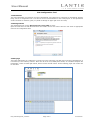
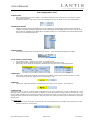
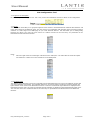
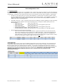
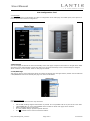
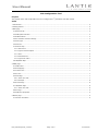
User Manual YCS Configuration Tool Purpose The purpose of the YCS Configuration Tool is to configure the 3 rd generation YCS cabin control. Index 1 Introduction............................................................................................................................................... 2 2 Getting started ........................................................................................................................................... 2 3 Main page ................................................................................................................................................. 2 3.1 Name and IP ........................................................................................................................................ 3 3.2 OLED panel selection ............................................................................................................................. 3 3.3 Enable buttons ..................................................................................................................................... 3 3.4 Air Condition common settings ............................................................................................................... 3 3.5 Main Light ............................................................................................................................................ 3 3.6 Main Lift .............................................................................................................................................. 3 3.7 Dimmer Map ........................................................................................................................................ 3 3.7.1 DMX count...................................................................................................................................... 3 3.7.2 Light circuit description .................................................................................................................... 4 3.7.3 Zone .............................................................................................................................................. 4 3.7.4 Entertainment ................................................................................................................................. 4 3.7.5 Light level matrix ............................................................................................................................ 5 3.8 Lift/Blinds Map...................................................................................................................................... 5 4 OLED page ................................................................................................................................................ 6 4.1 OLED name .......................................................................................................................................... 7 4.2 Startup page ........................................................................................................................................ 7 4.3 Volume zone ........................................................................................................................................ 7 4.4 AC zone ............................................................................................................................................... 7 4.5 Main Page ............................................................................................................................................ 7 4.5.1 Action and Text ............................................................................................................................... 7 4.5.2 Example ......................................................................................................................................... 8 4.6 Second Page ........................................................................................................................................ 8 4.7 Lift/Blinds Page..................................................................................................................................... 8 4.7.1 Action and Text ............................................................................................................................... 8 4.8 AC Page ............................................................................................................................................... 9 4.9 OLED text properties ............................................................................................................................. 9 5 Button page ............................................................................................................................................... 9 5.1 Function and Name ............................................................................................................................... 9 UM_YCS Config Tool_5.0.docx Page 1 of 9 07.05.2013 User Manual YCS Configuration Tool 1 Introduction The YCS Configuration Tool is based on an Excel spreadsheet. One cabin/zone is configured per spreadsheet. Besides being used as a configuration tool it can also be used as documentation for the actual project. In the spreadsheet useful comments are added to guide you (Small red triangle in upper right corner of a field). 2 Getting started The configuration tool requires Microsoft Excel version 2007 or newer. Open the Lantic.xlsm file with Microsoft Excel and enable macros. Now select “Save As” and select an appropriate name for the configuration sheet. 3 Main page The initial configuration of a cabin/zone is carried out on the main page (The first page in the Excel spreadsheet). It is divided up in the following sections: Name and IP of the YCS, OLED panel section, Air Condition fanspeed and temperature, section for Main light and lift, dimmer section and lift section. On the following pages each section will be described. UM_YCS Config Tool_5.0.docx Page 2 of 9 07.05.2013 User Manual YCS Configuration Tool 3.1 Name and IP Name that describes the zone is filled in. This will be displayed in the Lantic Service Tool and also used in the Central Command. IP address is filled in. This is only used as documentation and has no effect on the actual configuration. 3.2 OLED panel selection Enable the desired amount of OLED panels. A new tab/page is automatically generated when an OLED is enabled. If an OLED is disabled again the current configuration for that OLED page is preserved in the excel file but will not uploaded to the OLED panel. The OLED number 1-10 corresponds to the actual address/node that is set on the OLED panel itself. 3.3 Enable buttons When passive buttons are connected to the YCS server. A new tab will automatically be created. 3.4 Air Condition common settings Air Condition Count – select the amount of air condition zones. Adjust the common settings for the zones – Fanspeed and Temperature range. Select what zones should be presented in Entertainment and give them an appropriate name. 3.5 Main Light Select what “Main Light” should be controlled from the RC20 remote control. The RC1 and RC10 remote controls always utilize the default Scene 1 in the Dimmer map. 3.6 Main Lift Select what “Main Lift” should be controlled from the Lantic remote controls – RC1 and RC10. 3.7 Dimmer Map The Dimmer map is used to create the light configuration for the entire cabin/zone. A uniqe combination of a zone and light name is created. Light level values are filled in to define the collection of light circuits. The topmost 6 rows are the lights controlled from the Central command. If prefered these 6 rows can frealy be used. The order of the names and zones created in this Excel sheet is the same order they will be presented in the Entertainment and RC20 iPxd interface. 3.7.1 DMX count Adjust this value if more than 22 DMX circuits are used (maximum 32). The DALI count (maximum 10) will then be reduced by equal amount. UM_YCS Config Tool_5.0.docx Page 3 of 9 07.05.2013 User Manual YCS Configuration Tool 3.7.2 Light circuit description Fill in a description for the light circuit. This is only used as documentation and has no effect on the configuration. 3.7.3 Zone The Zone name will enable you to group the light and scene names in The Entertainment and RC20 iPxd interface. Fill in the Zone names for the different zones. The zone name is an combination with the light name used when making a selection on a later stage on an OLED page. If you create identical “Names” this will enable you to destinguesing between the names. The order the zone names are created will also be the order they are presendted in the Entertainment and RC20 iPxd interface Name Fill in the Light names for all the light collections for the cabin/zone. The name filled in should be capitaland maximum 7 letters due to the restrictions on the OLED panel. 3.7.4 Entertainment The different light collections can also be controlled from the Entertainment menu and on the different devices that can control the light environment. The available options are: Scene and Lights. If nothing is selected (Empty) the light collection is not shown in the Entertainment menu. If Scene is selected the light collection is displayed in the Entertainment Scene menu. If Lights are selected the light collection is displayed in the Entertainment Lights menu. The order the names are created will also be the order they are presendted in the Entertainment and RC20 iPxd interface. UM_YCS Config Tool_5.0.docx Page 4 of 9 07.05.2013 User Manual YCS Configuration Tool 3.7.5 Light level matrix For each created zone and light name it is possible to fill in a light level value for the dimmer circuits that should be controlled (1-100%). The light level configuration is the same for both DMX and DALI groups. In the following example DMX is configured. The created zone and name can be selected on a later stage on OLED or a button page. Example: A zone called “Main” and a name called “BRIGHT” is created. DMX1-3 is filled in with the values 80. On an OLED page this certain combination of zone and name is selected – name “BRIGHT” is going to be displayed in OLED. The function Light set is selected. Now in real life when clicking “BRIGHT” button the DMX1-3 will turn on at 80% light level. Valid light values are 1-100%. The filled in light value has a different meaning depending on what controlling device uses this light collection and how the controlling device is configured. (OLED, button, RC20 and Entertainment). o OLED LIGHT SET: Light is set to this level. o OLED LIGHT TOGGLE: Any value filled in (1-100) will toggle the light on/off. o Button LIGHT SET: Light is set to this level. o Button LIGHT TOGGLE: Any value filled in (1-100) will toggle the light on/off. o Entertainment/RC20 SCENE: Light is set to this level. o Entertainment/RC20 LIGHTS: Any value filled in (1-100) will enable you to dim light up/down. Special advanced commands are TOG and CLR. o CLR is used for a LIGHT set and SCENE function. A light circuit with this value will be turned off. This can for example be used for a button on an OLED called “OFF” – when pressed light goes off. o TOG is used in combination with light values 1-100% and a toggle function. It is intended as an “Only off function” to ensure certain light circuit is turned off. When light is toggled off this circuit(s) will turn off. When light is toggled on light circuit(s) will not turn on. 3.8 Lift/Blinds Map The Lift/Blind map is used to create the Lift and Blind configuration for the entire cabin/zone. The functionality and concept is the same as the Dimmer map. A uniqe combination of a zone and name is created. Timeout values are filled in to define what relay outputs should be activated. 1-30 seconds corressponds to the timeout in seconds. 0 seconds defines that relay turns permenalty on when “up” is pressed and permanently off when down is pressed. For “Entertainment” the Name can be located in the Lift or Curtain menu. Note that it is only the names actually selected on the later OLED Lift/Blinds page that can be controlled and are presented on the Entertainment monitor. UM_YCS Config Tool_5.0.docx Page 5 of 9 07.05.2013 User Manual YCS Configuration Tool 4 OLED page An OLED Excel page is created for each OLED keypad in the cabin/zone. Each available OLED menu (Main Page, Second Page, AC Page and Lift/Blinds Page) are displayed. UM_YCS Config Tool_5.0.docx Page 6 of 9 07.05.2013 User Manual YCS Configuration Tool 4.1 OLED name This is used to describe the location of the panel. This is only used as documentation and has no effect on the configuration. 4.2 Startup page This is used to select what page should be displayed when the panel is starting up (Typically Main page). If another page is selected the panel is locked to that page (Not possible to navigate to other menus). 4.3 Volume zone What zone should the volume buttons control. (1 = Primary zone, 2 = Secondary zone, 3 = Tertiary zone). 4.4 AC zone What zone should the air condition page control (1-3). 4.5 Main Page Main page is the typically startup page and is used for the primary function and navigation to the lower menus. 4.5.1 Action and Text Button actions can be selected in the drop down box. Note the a button that is assigned a light action can as default always dim up/down the light by holding down the button. NO ACTION: Nothing happens when button is pressed. It is not possible to fill in any text in the “Text” field. LIGHT SET: In “Text” field light names created on Excel main page can be selected. Light is set to this level when pressed. LIGHT TOGGLE: In “Text” field light names created on Excel main page can be selected. Light is toggled on/off. SECOND PAGE: Any name can be filled in “Text field. Navigated to Second Page. LIFT/BLINDS PAGE: Any name can be filled in “Text field. Navigated to Lift/Blinds page. AC: Any name can be filled in “Text field. Navigated to Air-condition Page. UP: Volume control. When selected a standard up symbol is added to the text field. It is also possible to fill in another name. DOWN: Volume control. When selected a standard down symbol is added to the text field. It is also possible to fill in another name. It is possible to fill in names in-between buttons – in this case the text “VOLUME”. UM_YCS Config Tool_5.0.docx Page 7 of 9 07.05.2013 User Manual YCS Configuration Tool 4.5.2 Example The following picture is an illustration of a filled in configuration of the main page of an OLED panel, and a picture of how the panel looks with that configuration. 4.6 Second Page The second page has almost the same functionality as the main page except from the Action to navigate back. OLED will always return automatically to main page after a few seconds of inactivity but it is advised always to assign a “Back” function on lower menus. Refer to main page for details. 4.7 Lift/Blinds Page This page is used to control Lift and/or blinds. If selected as startup page the upper button, “BACK” can be utilized as a LIFT/BLIND SET Action and thereby the page can control 5 collections. 4.7.1 Action and Text Button actions can be selected in the drop down box. NO ACTION: Nothing happens when button is pressed. It is not possible to fill in any text in the “Text” field. LIFT/BLINDS SET: In “Text” field Lift/Blind names created on Excel main page can be selected. BACK: Navigates back to main page. It is not possible change up/down symbols and text. It is not possible to fill in names in-between buttons. UM_YCS Config Tool_5.0.docx Page 8 of 9 07.05.2013 User Manual YCS Configuration Tool 4.8 AC Page The Air-condition page cannot be changed in any way. It is possible to navigate to the Air-condition page from the main- or second page. 4.9 OLED text properties It is possible to enter texts of up to 7 letters, which consists of capital letters (A to Z), numbers (0-9) and the symbols “/”, “▲”, “▼” When YCS Service Tool imports the Excel file the OLED panel can at most show 9 text lines per page. 5 Button page If passive buttons are connected to the YCS server the functionality of each of the buttons can be entered in the Button collection sheet. In this sheet 6 different button collections are shown (Button Collection 1-6). Each collection consists of 6 buttons, which default is set to have no action. Button Collection 1 corresponds to buttons connected directly to the YCS Server. Button Collection 2-6 corresponds to buttons connected via MPX breakout PCB´s. 5.1 Function and Name No ACTION: Nothing happens when button is pressed. LIGHT SET: Light is set to this level when pressed. LIGHT TOGGLE: Light is toggled on/off when pressed. In the “Name” field light names created on Excel main page can be selected. UM_YCS Config Tool_5.0.docx Page 9 of 9 07.05.2013