1
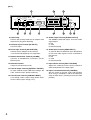
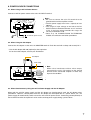
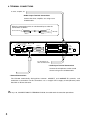
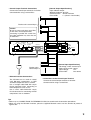
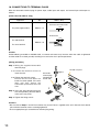
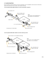
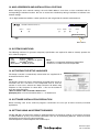
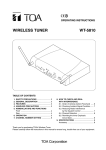
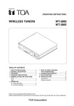
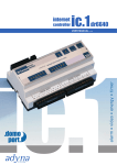
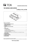
USER'S MANUAL
PLEASE READ THIS MANUAL FIRST!
NETWORK AUDIO ADAPTER
NX-100
Please follow the instructions in this manual to obtain the optimum results from this unit.
We also recommend that you keep this manual handy for future reference.
TABLE OF CONTENTS
1.
2.
3.
4.
5.
6.
7.
8.
9.
10.
11.
12.
13.
14.
15.
16.
SAFETY PRECAUTIONS .............................................................................................................. 1
COMPOSITION OF THE NX-100 INSTRUCTION MANUAL ........................................................ 3
PARTS INCLUDED WITH THE PACKAGE .................................................................................. 3
GENERAL DESCRIPTION ............................................................................................................ 4
FEATURES .................................................................................................................................... 4
HANDLING PRECAUTIONS ......................................................................................................... 5
NOMENClATURE AND FUNCTIONS ........................................................................................... 5
POWER SOURCE CONNECTIONS .............................................................................................. 7
TERMINAL CONNECTIONS ......................................................................................................... 8
CONNECTIONS TO TERMINAL PLUGS ..................................................................................... 10
RACK MOUNTING ....................................................................................................................... 11
MAC ADDRESSES AND INSTALLATION LOCATIONS ............................................................ 12
SYSTEM CONDITIONS ................................................................................................................ 12
ACTIVATING THE SETUP LAUNCHER ...................................................................................... 12
SOFTWARE INSTALLATION PRECAUTION ............................................................................. 12
SETTING USING AN INTERNET BROWSER ............................................................................. 12
1. SAFETY PRECAUTIONS
• Be sure to read the instructions in this section carefully before use.
• Make sure to observe the instructions in this manual as the conventions of safety symbols and messages
regarded as very important precautions are included.
• We also recommend you keep this instruction manual handy for future reference.
Safety Symbol and Message Conventions
Safety symbols and messages described below are used in this manual to prevent bodily injury and property
damage which could result from mishandling. Before operating your product, read this manual first and
understand the safety symbols and messages so you are thoroughly aware of the potential safety hazards.
WARNING
Indicates a potentially hazardous situation which, if mishandled, could
result in death or serious personal injury.
When Installing the Unit
• Do not expose the unit to rain or an environment where it may be splashed by water or other liquids, as
doing so may result in fire or electric shock.
• Use the unit only with the voltage specified on the unit. Using a voltage higher than that which is specified
may result in fire or electric shock.
• Do not cut, kink, otherwise damage nor modify the power supply cord. In addition, avoid using the power
cord in close proximity to heaters, and never place heavy objects -- including the unit itself -- on the power
cord, as doing so may result in fire or electric shock.
• Avoid installing or mounting the unit in unstable locations, such as on a rickety table or a slanted surface.
Doing so may result in the unit falling down and causing personal injury and/or property damage.
When the Unit is in Use
• Should the following irregularity be found during use, immediately stop the power supply to the unit by
disconnecting the AC adapter from the AC outlet or the DC power cords from the unit terminals, then
contact your nearest TOA dealer. Make no further attempt to operate the unit in this condition as this may
cause fire or electric shock.
·
·
·
·
·
If you detect smoke or a strange smell coming from the unit.
If water or any metallic object gets into the unit
If the unit falls, or the unit case breaks
If the power supply cord is damaged (exposure of the core, disconnection, etc.)
If it is malfunctioning (no tone sounds.)
• To prevent a fire or electric shock, never open nor remove the unit case as there are live electrical parts
inside the unit. Refer all servicing to your nearest TOA dealer.
• Do not place cups, bowls, or other containers of liquid or metallic objects on top of the unit. If they
accidentally spill into the unit, this may cause a fire or electric shock.
• Do not insert nor drop metallic objects or flammable materials in the gaps around the rear-mounted
connectors, as this may result in fire or electric shock.
• Do not touch the unit and the AC adapter plug during thunder and lightning, as this may result in electric
shock.
CAUTION
Indicates a potentially hazardous situation which, if mishandled, could
result in moderate or minor personal injury, and/or property damage.
When Installing the Unit
• Never plug the AC power supply plug into nor remove it from an AC outlet with wet hands, as doing so may
cause electric shock.
• When unplugging the power supply cord, be sure to grasp the power supply plug; never pull on the cord
itself. Operating the unit with a damaged power supply cord may cause a fire or electric shock.
• When moving the unit, be sure to remove its power supply cord from the wall outlet. Moving the unit with the
power cord connected to the outlet may cause damage to the power cord, resulting in fire or electric shock.
When removing the power cord, be sure to hold its plug to pull.
• Avoid installing the unit in humid or dusty locations, in locations exposed to the direct sunlight, near the
heaters, or in locations generating sooty smoke or steam as doing otherwise may result in fire or electric
shock.
When the Unit is in Use
• Use the AC adapter AD-246 (optional) or the equivalent.
As for the usable adapter, consult your TOA dealer.
Note that the use of an adapter other than specified may cause a fire.
• If dust accumulates on the power supply plug or in the wall AC outlet, a fire may result. Clean it periodically.
In addition, insert the plug in the wall outlet securely.
• Disconnect the power supply cable and connector for safety purposes when cleaning or leaving the unit
unused for 10 days or more. Doing otherwise may cause a fire or electric shock.
2
2. COMPOSITION OF THE NX-100 INSTRUCTION MANUAL
The NX-100 Instruction Manual is divided into three parts: User's Manual (entitled as "PLEASE READ THIS
MANUAL FIRST"), Installation Setup, and Operations. Before installation or use, be sure to refer to the
pertinent information included in these manuals in order to familiarize yourself with its correct operation.
USER'S MANUAL
(PLEASE READ THIS MANUAL FIRST)
For unit installation
For unit's network settings
Installation Setup manual
CD
For broadcast management and setup
For broadcasting operation
Operations manual
3. PARTS INCLUDED WITH THE PACKAGE
Check to be sure that all the following components are included with the unit.
Program CD ........................................................................................................................... 1
RS-232C connector cover ............................................................................................ 1
Machine screw M3 x 10 .................................................................................................. 8
3-pin removable terminal plug (for power supply) .......................................... 1
3-pin removable terminal plug (for audio I/O) .................................................... 2
9-pin removable terminal plug (for control I/O) ................................................. 2
USER'S MANUAL (PLEASE READ THIS MANUAL FIRST) ................. 1
[CD File Configuration]
CD
NX-100 Software
These dedicated programs permit the NX-100 to
be operated from a connected PC.
NX-100 Setup Program
NX-100 Operation Program
Installation Setup Manual (.pdf file)*
Operations Manual (.pdf file)*
Java Runtime
(Java 2 Runtime Environment)
* Acrobat Reader is required to view these files.
If Acrobat Reader is not already installed in your
PC, please use the installer program included on
the CD (Refer to attached ReadMe file for
installation instructions.)
Adobe Acrobat Reader
Notes
ReadMe
• Adobe and Acrobat Reader are trademarks of
Adobe Systems Incorporated.
• Java is a trademark of Sun Microsystems, Inc.
[Update information]
• The latest versions of the following software and manuals are open to the public on the Toa's download site
http://www.toa-products.com/international/: NX-100 firmware, NX-100 software (Setup program and
Operation program), and Instruction manuals (Installation setup manual and Operations manual). Please
download them from the above web site.
• To confirm the NX-100 firmware version or to update the firmware, use the system setting tool of the setup
program. For details, refer to the installation setup manual.
• To confirm the NX-100 software version, use the Help menu of the software.
• The version of each instruction manual is in the lower right corner on the last page expressed in a yearmonth format. Example: "200304" represents 2003, April.
3
4. GENERAL DESCRIPTION
TOA's NX-100 Network Audio Adapter is specially developed to transmit high-quality audio signals and such
control data as serial data over IP networks such as LAN or Internet in real time.
[Audio Signal Flow Chart]
Audio signal (1)
Amplifier
CD or other music player
Mixer
Speaker
Audio signal (2)
NX-100
PC with NX-100
software installed
Microphone
LAN / WAN
Mixer
NX-100
Microphone
CD or other music player
Amplifier
Speaker
5. FEATURES
• Permits use of not only dedicated lines, but also the Internet, which greatly reduces operating costs when
transmitting audio signals to remote locations.
• Under peak conditions with no network delay, audio signals can be transmitted with a minimal delay of about
20 ms.
• Transmission of control data, such as contact and serial data, possible.
• Simultaneous bi-directional transmission of audio signals possible.
• Simultaneous transmission of audio signals to multiple locations (up to 4 locations for unicast*1 streaming,
64 locations for multicast*2 streaming) possible.
• Enables loss-free audio signal transmission even over congested networks such as the Internet.
• The entire system can be remotely operated or managed from a single PC (personal computer) using the
supplied software program.
• Because audio transmissions can be started and finished via the unit's contact inputs, systems can be
configured even without the use of a personal computer.
• Designed to operate on both AC and DC power sources.
*1 UNICAST:
A communications method used to transmit audio data to designated addresses in a matched
ratio of 1:1. Up to 4 channels can be simultaneously transmitted.
*2 MULTICAST: A communications method used to simultaneously transmit a single audio data source to
multiple destinations.
4
6. HANDLING PRECAUTIONS
• Warning: This is a class A products. In a domestic environment this product may cause radio interference in
which case the user may be required to take adequate measures.
• Note: This equipment has been tested and found to comply with the limits for a Class A digital device,
pursuant to Part 15 of the FCC Rules. These limits are designed to provide reasonable protection
against harmful interference when the equipment is operated in a commercial environment. This
equipment generates, uses, and can radiate radio frequency energy and, if not installed and used in
accordance with the instruction manual, may cause harmful interference to radio communications.
Operation of this equipment in a residential area is likely to cause harmful interference in which case
the user will be required to correct the interference at his own expense.
• The user that changes or modifications not expressly approved by the party responsible for compliance
could void the user's authority to operate the equipment.
• Avoid soldering stranded or shielded cable, as contact resistance may increase when the cable is tightened
and the solder is crushed, possibly resulting in an excessive rise in joint temperatures.
• Avoid exposing the unit to strong shocks or vibration, which could damage the unit.
• Do not use the unit in close proximity to TV sets or radios in order to avoid reception interference.
• Take care to only use the unit in locations having an ambient temperature within the range of 0 – 50°C (0 –
40°C when using the AC adapter), and humidity of less than 90% (no condensation).
• When mounting in an equipment rack, take care not to install the unit in close proximity to power amplifiers,
as the higher resulting temperatures could exceed the unit's maximum permissible operating temperature
limit.
• To clean, be sure to first cut off power to the unit, then wipe with a dry cloth. When the unit gets very dirty,
use a cloth damped in a neutral cleanser. Never use benzene, thinner or chemically-treated cleaning cloth
because such volatile liquids could deform or discolor the unit.
7. NOMENCLATURE AND FUNCTIONS
[Front]
4
3
5
6
NETWORK AUDIO ADAPTER NX-100
LNK/ACT
FD/COL
STATUS
ERROR
RUN
RESET
00-05-F9-FF-80-81
1
2
1. LNK/ACT Indicator (Green)
Lights when the unit is connected to a network.
Flashes while the unit is transmitting or receiving
data.
2. FD/COL Indicator (Yellow)
Remains lit while the network is in full-duplex
communications mode.
Flashes whenever data collision is detected.
3. Status Indicator (Yellow)
Remains lit during broadcasts.
Flashes while the unit is writing data into the
internal storage medium (flash memory).
7
4. Error Indicator (Red)
Lights if an error is detected during transmission,
etc.
5. Run Indicator (Green)
Remains lit during normal operation.
Flashes at 2-second intervals when a failure is
detected.
6. Reset Button
Restarts the unit when pressed.
7. MAC Address
The unit's MAC address consists of 12
hyphenated alphanumeric characters.
5
[Rear]
13
8
CONTACT OUTPUT
1 2 3 4 5 6 7 8 C
H C E
AUDIO OUTPUT
DC INPUT
24V
FG
AC ADAPTER
200mA DC INPUT
24V 200mA 10/100M
15
INPUT
VOLUME
RS-232C
LINE MIC
CONTACT INPUT
9
10
11
12
8. Cord Clamp
Pinches and securely holds the AC adapter cord
to prevent its plug from detaching.
9. DC Power Input Terminal [DC INPUT]
A 24 V DC input.
10. Power Input Terminal [AC ADAPTER]
Connect the AC adapter* to this terminal.
* Use the AD-246 (optional) or its equivalent.
11. Network Connection Terminal [10/100M]
Connects to 10/100 Base-T networks. (RJ-45
Ethernet jack)
12. RS-232C Terminal
A 9-pin D-sub connector (male).
13. Control Output Terminal [CONTACT OUTPUT]
An open collector output (Withstand voltage: 30
V DC, Control current: 50 mA maximum).
14. Control Input Terminal [CONTACT INPUT]
A no-voltage "make" contact input (Short circuit
current: 10 mA, Open voltage: 12 V).
6
1 2 3 4 5 6 7 8 C
14
H C E
16
AUDIO INPUT
17 18
15. Audio Output Terminal [AUDIO OUTPUT]
A 0 dB/600 Ω balanced output. Line level audio
signal output.
H: Hot
C: Cold
E: Ground (shield)
16. Audio Input Terminal [AUDIO INPUT]
A –58 to 0 dB/2 kΩ balanced input. Microphone
or line level audio signals can be connected to
this terminal.
H: Hot
C: Cold
E: Ground (shield)
17. Input Volume Control [INPUT VOLUME]
Adjusts the audio input level. Set this control to
eliminate distortion in the input signal.
18. Input Level Selection Switch [LINE/MIC]
Set this switch to the MIC (right side) position
when using a microphone, and to the LINE (left
side) for other inputs. (Factory-preset to the LINE
position.)
8. POWER SOURCE CONNECTIONS
8.1. When Using a 24V DC Power Source
Connect a 24V DC power source to the unit's DC INPUT terminal.
CONTACT OUT
DC INPUT AC ADAPTER
24V
FG
200mA DC INPUT
24V 200mA 10/100M
RS-232C
CONTACT I
To 24V DC power source
Notes
• Be sure to connect the unit's FG terminal to the
ground terminal of the amplifier or mixer.
• The DC power supply must have a capacity of over
200 mA.
• The range of input voltage to be fed to the DC
INPUT terminal should be between 21.6 V and 26.4
V DC. If the input voltage exceeds this range, the
unit may malfunction or fail.
• Refer to p. 10, CONNECTIONS TO TERMINAL
PLUGS, for connector connection procedures.
8.2. When Using the AC Adapter
Connect the AC adapter* to the unit's AC ADAPTER terminal. Pinch the cord with a clamp and securely fix it.
* Use the AC adapter AD-246 (optional) or the equivalent.
As for the usable adapter, consult your TOA dealer.
AC adapter
Cord clamp
CONTACT OUTPU
DC INPUT
24V
FG
200mA
DC24V
200mA
10/100M
RS-232C
Note
When noise interference affects voice output,
connecting the unit's FG terminal to the ground
terminal of the connected amplifier or mixer may
improve the condition.
CONTACT INPU
8.3. When Simultaneously Using the 24V DC Power Supply and the AC Adapter
When both the 24V DC power supply and the AC adapter are simultaneously used, the AC adapter takes
precedence. However, should power from the AC adapter be interrupted due to a power failure, etc., the
power supply will automatically switch over to the unit's 24V DC power source. Connecting a battery directly to
the DC INPUT terminal also permits it to be used as backup power supply during a power failure.
7
9. TERMINAL CONNECTIONS
To mixer, amplifier, etc.
• Audio Output Terminal Connections
Connect the mixer, amplifier, etc. using 2-core
shielded cable.
When the connected unit has an unbalanced input, make the
connections as follows:
Connected Unit
H
E
Hot (H)
Cold (C)
Earth (E)
Shield
CONTACT OUTPUT
DC INPUT
24V
FG
NX-100
Shield
1 2 3 4 5 6 7 8 C
H C E
AUDIO OUTPUT
AC ADAPTER
200mA DC INPUT
24V
200mA 10/100M
INPUT
VOLUME
RS-232C
LINE MIC
CONTACT INPUT
1 2 3 4 5 6 7 8 C
H C E
AUDIO INPUT
To microphone or
other sound sources
• Audio Input Terminal Connections
Connect the microphone or other sound
sources using 2-core shielded cable.
• Network Connections
The NX-100 automatically distinguishes between 10BASE-T and 100BASE-TX networks, and
establishes a connection. For this connection, use a "straight" UTP Category 5 LAN (Ethernet) cable
fitted with an RJ-45 connector.
Tip
Refer to p. 10, CONNECTIONS TO TERMINAL PLUGS, for audio terminal connection procedures.
8
• Control Output Terminal Connections
[Control Output Specifications]
Open collector output
Withstand voltage: 30 V DC
Control current:
50 mA maximum
Pulse width:
1 s (when in Latch mode)
Connect the control input terminals of all other
connected units using 2 control lines.
To other unit's control input
Caution
Be sure to connect only these control lines
to other unit's control input terminals.
Connecting in parallel with control lines
from other equipment may cause the unit
to malfunction.
CONTACT OUTPUT
DC INPUT
24V
FG
1 2 3 4 5 6 7 8 C
H C E
AUDIO OUTPUT
AC ADAPTER
200mA DC INPUT
24V
200mA 10/100M
INPUT
VOLUME
RS-232C
LINE MIC
CONTACT INPUT
To other unit's
control output
1 2 3 4 5 6 7 8 C
H C E
AUDIO INPUT
[Control Input Specifications]
No-voltage "make" contact input
Short circuit current: 10 mA
Open voltage:
12 V
Pulse width:
Over 50 ms
• RS-232C Interface Connections
The NX-100 can be used to control
such RS-232C components as DTE
and DCE components over a network.
Use a "straight" cable fitted with a 9-pin
D-sub connector when connecting to
DTE components such as PCs.
Use a "cross" cable fitted with a 9-pin
D-sub connector for connecting to DCE
components such as modems.
• Connections to the Control Input Terminal
Connect the control output terminals of all other
connected units using 2 control lines.
Tips
• Refer to p. 10, CONNECTIONS TO TERMINAL PLUGS, for control terminal connection procedures.
• When not using the RS-232C interface, place the supplied RS-232C cover over the terminal to protect it
against dust.
9
10. CONNECTIONS TO TERMINAL PLUGS
Wire the removable terminal plug for power input, audio input and output, and control input and output as
follows:
[Cable size and width to strip]
Application
Size
Width to Strip
Solid cable and stranded cable
For power supply terminal
7 mm
AWG24 – 12
Shielded cable
7 mm
For audio terminal
AWG28 – 16
For control terminal
15 mm
Caution
Avoid soldering stranded or shielded cable, as contact resistance may increase when the cable is tightened
and the solder is crushed, possibly resulting in an excessive rise in joint temperatures.
[Wiring procedure]
Step 1. Wiring the supplied removable
terminal plugs.
NX-100 rear panel
1-1. Loosen the terminal screws to
insert the wire.
1-2. Tighten the terminal screws.
Ensure that the wire does not
break free when pulled. If the wire
does pull free, repeat the
connection procedure from the
start.
Removable
terminal plugs
(Supplied with
the NX-100)
Tighten
H
C
E
AU
DIO
OU
TP
UT
INP
U
VO T
LU
ME
2
H
1
C
L IN
E
E
AU
DIO
I
Step 2. Insert the wired terminal plug into
the corresponding terminal block
in the unit's rear panel.
MIC
NP
UT
3
Step 3. Tighten the fixing screws.
Tighten
Cautions
• Do not reverse Steps 1 and 2. Poor contact may result if force is applied to the unit's internal circuit board
pins while the terminal screws are being tightened.
• Use an appropriate type screwdriver for terminal plug wiring.
10
11. RACK MOUNTING
Use the optional mounting hardware set when installing the unit in an equipment rack. Be sure to remove the
rubber feet located on the unit's bottom surface before mounting.
• Use the optional MB-15B-BK hardware set when mounting a single unit.
3 x 4 tapping screw*
M3 x 10 machine screw
(supplied with NX-100)
Note
Do not use the screws supplied with the
MB-15B-BK to secure the NX-100.
NX-100
Blank bracket*
NE
TW
ORK
AU
LN
K/AC
T
DIO
AD
FD
/COL
AP
TE
R NX
-100
ST
AT
US
ER
RO
R
RU
N
RE
00
SE
M3 x 10 machine screw
(supplied with NX-100)
T
-05
-F9
-F
F-8
0-8
1
5 x 12 rack mounting screw*
Rack mounting bracket*
Fiber washer (for M5)*
* Component parts of MB-15B-BK
• Use the optional MB-15B-J hardware set when mounting 2 units.
M3 x 10 machine screw (supplied with NX-100)
Note
Do not use the screws supplied with the
MB-15B-BK to secure the NX-100.
NX-100
NE
TW
ORK
AU
DIO
LN
K/AC
T
AD
AP
FD
/COL
TE
R NX
-100
ST
AT
US
ER
RO
R
RU
N
RE
Fiber washer (for M5)*
SE
NX-100
T
00
-05
-F
9-F
F-8
0-8
1
NE
TW
ORK
AU
LN
K/AC
T
FD
DIO
/COL
AD
AP
TE
R NX
-100
ST
AT
5 x 12 rack mounting screw*
US
ER
RO
R
RU
N
RE
SE
00
-05
-F
T
9-F
F-8
0-8
1
Coupler*
* Component parts of MB-15B-J
M3 x 10 machine screw
(supplied with NX-100)
Rack mounting bracket*
M3 x 6 oval head screw*
11
12. MAC ADDRESSES AND INSTALLATION LOCATIONS
When making the unit's network settings, the unit's MAC address* must have a clear association with its
corresponding installation location. Be sure to record the relationship during installation to facilitate later
network settings.
* A 12-digit hexadecimal address number peculiar to and assigned to the network-connected unit.
NETWORK AUDIO ADAPTER NX-100
LNK/ACT
FD/COL
STATUS
ERROR
RUN
RESET
00-05-F9-FF-80-81
MAC address
13. SYSTEM CONDITIONS
The following minimum PC (personal computer) specifications are required in order to correctly operate the
unit's software program.
• OS:
Windows 2000/XP
• CPU:
Pentium 800 MHz or greater
• RAM:
256 MB or greater
• Disk Space: 40 MB or greater
Notes
• Windows is a trademark of Microsoft Corporation.
• Pentium is a trademark of Intel Corporation.
14. ACTIVATING THE SETUP LAUNCHER
The Setup Launcher is automatically started when the supplied CD is
inserted into the PC's drive.
Note
The Setup Launcher will not be automatically activated when the CD is
inserted if the PC's CD drive is not compatible with an auto-run
function. In such cases, execute the "Setup Launcher" file below using
"Explorer" or "My Computer" or select Start → Run on the taskbar to
enter the command below:
<Drive in which a CD is inserted> \Autorun.exe
[Example] When a CD is inserted into drive e → e:\Autorun.exe
15. SOFTWARE INSTALLATION PRECAUTION
When installing each of the software programs contained in the CD, quit all other currently activated
applications.
16. SETTING USING AN INTERNET BROWSER
The NX-100 does not exclusively require its dedicated software to change its settings. It can also be set using
a standard browser by way of an internet connection. Use one of the following browsers ,which have been
confirmed to ensure the unit's correct operation:
Internet Explorer 6, Internet Explorer 5.5 or Netscape 7.
Printed in Japan
133-12-828-8A