1
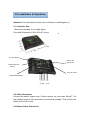
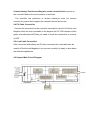
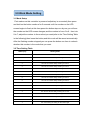
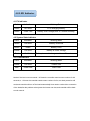
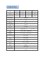
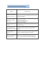
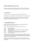
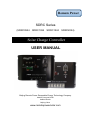
Remote Power
SDRC Series
(SDRC0524 SDRC1024 SDRC1524 SDRC2024)
Solar Charge Controller
USER MANUAL
Beijing Remote Power Renewable Energy Technology Company
Add:3/F,Huayuan Road
Haidian District
Beijing,China
www.remotepowersolar.com
Contents
1.0 Features………………………………………….......1
2.0 Installation & Operation……………………………2
2.1 Controller Size
2.2 Cable Information
2.3 Battery Cable Connection
2.4 PV Cable Connection
2.5 Load Cable Connection
2.6 System Main Circuit Diagram
3.0 Work Mode Setting…………………………………4
3.1 Mode Setup
3.2 Time Setting Table
4.0 LED Indicator……………………………….............5
4.1 PV Indicator
4.2 Battery Indicator
4.3 Load Indicator
5.0 Specification…………………………………….......6
6.0 Problem and Trouble Shooting………………......7
7.0 Warranty................................................................8
1.0 Features
Control: Micro Controller Unit utilizing dedicated software and SCM for
precise control.
Charging mode: Pulse Width Modulated control, allows for high efficiency
boost, recovery and float charging. Temperature compensation ensures that
these parameters are adjusted for maximum battery condition and hence,
prolonged battery life.
High accuracy discharging control: Over-discharging control voltage
modified by the battery discharging rate curve.
Circuit Protection: protection against overload, short circuit and reverse
connection, Built in Transient Voltage Suppression protects against lightning.
Reverse current leakage through PV panel is blocked. Batteries are prevented
from over-charging or discharging.
LED indication on system condition: Indicating LED’s, monitor battery
charging levels as well as battery state. LED monitoring of load conditions such
as over load and short circuit as well as load on/off, are also provided.
Design standard: Operating temperature range from -35 to +50 deg C.
No adjustable hardware part: Controller accuracy, stability and reliability is
assured by the use of flash memory for all control parameters and set-points.
Operation and Design: easy to operate, robust in design.
Control modes: Choose the code by press the button
2.0 Installation & Operation
Attention: Connect battery first,be care of Positive(+) and Negative(-)
2.1 Controller Size:
Mount the controller in a suitable place.
Controller Dimensions: 140×90.5×27.2(mm)
PV LED indicator
Work mode
Digit set key
System state LED
indicator
ON/OFF button
Load LED indicator
+-+
PV Bat
-+
-
Load
2.2 Cable Information
Choose the plastic Copper wire. Current density no more than 4A/mm2. Cut
the suitable length of wire and make it as shout as possible. Peel off 5mm the
plastic at the end of wire.
2.3 Battery Cable Connection
Connect battery Positive and Negative to the controller first to power on
the controller.Make sure correct polarity of terminals.
The controller has protection of reverse polarity,so even not connect
correctly for positive and negative,the controller will not be burned.
2.4 PV Cable Connection
Connect the solar panel to the controller terminals,be careful of Positive and
Negative.when the sun is available in the daytime,the PV LED indicator will be
green color,otherwise NOT,then you need to check the connection is correctly
or NOT.
2.5 Load Cable Connection
After connected with battery and PV,then connected the Load cable,also be
careful of Positive and Negative,if not connect correctly,it is easily to burn down
the electrical appliances.
2.6 System Main Circuit Diagram
3.0 Work Mode Setting
3.1 Mode Setup
First make sure this controller is powered on(battery is connected),then press
and hold on the button continue for 5 seconds until the number on the LED
screen begins to flash,at this time,press the button step one by one,you will see
the number on the LED screen changes,and the number is from 0 to 9,then into
0.to 7.,adjust the number to the one that you want(refer to the Time Setting Table
in the following),then loose the button,and this mode will be saved automatically.
After the flashing number stopped,you can press the button one time to recheck
whether this number is the mode that you want.
3.2 Time Setting Table
LED Display
Working Mode
0
Sun set+10 minutes delay+working for the whole night
1
Sun set+10 minutes delay+working for 1 hour
2
Sun set+10 minutes delay+working for 2 hour
3
Sun set+10 minutes delay+working for 3 hour
4
Sun set+10 minutes delay+working for 4 hour
5
Sun set+10 minutes delay+working for 5 hour
6
Sun set+10 minutes delay+working for 6 hour
7
Sun set+10 minutes delay+working for 7 hour
8
Sun set+10 minutes delay+working for 8 hour
9
Sun set+10 minutes delay+working for 9 hour
0.
Sun set+10 minutes delay+working for 10 hour
1.
Sun set+10 minutes delay+working for 11 hour
2.
Sun set+10 minutes delay+working for 12 hour
3.
Sun set+10 minutes delay+working for 13 hour
4.
Sun set+10 minutes delay+working for 14 hour
5.
Sun set+10 minutes delay+working for 15 hour
6.
Manual ON/OFF
7.
Sun set+working for testing for the whole night
4.0 LED Indicator
4.1 PV Indicator
Color
Indication
Working State
Green
On Solid
PV is charging Battery
Green
Flash Fast
Battery Over Voltage,refer to Trouble shooting.
4.2 System State Indicator
Color
Indication
Working State
Green
On Solid
Battery is Normal
Green
Flash
Battery is full
Yellow
On Solid
Battery is under voltage
Red
On Solid
Battery is over discharge and turn off Load
4.3 Load Indicator
Color
Indication
Working State
Yellow
On Solid
Load is ON
Red
Flash slow
Over Load
Notice:If the load current exceeds 1.25 times the controller rated current continue for 60
seconds,or 1.5 times the controller rated current continue for 5s,over load protection will
work,and controller will turn off the load automatically.User need to recheck the connection
of the load,after the problem solved,press the button one time,and controller will be back
to work normal.
5.0 Specification
Type
SDRC0524
SDRC1024
SDRC1524
SDRC2024
Rated charge
current
5A
10A
15A
20A
Rated load current
5A
10A
15A
20A
Work voltage
12/24V auto
No load current
≤6mA
Charging circuit
voltage drop
≤0.26 V
Load circuit voltage
drop
≤0.15 V
Over voltage
protection
17V; ×2/24V;
Industry stage:-35
Work temperature
℃ to +55℃
;
Boost charge
voltage
14.6V;×2/24V; (keep 10min)
Direct charge
voltage
14.4V; ×2/24V; (keep 10min)
Float charge voltage
13.6V; ×2/24V;
charge return
voltage
13.2v;×2/24V;
Temperature
compensation
℃/
-5mv/
return voltage);
Lower voltage
indicate
12.0V; ×2/24V;
Over discharge
voltage
11.1V(no load)- real-time modified voltage by the discharge rate;
×2/24V;
Over discharge
return voltage
12.6V; ×2/24V
Control mode
PWM charge mode; modified discharge voltage by the discharge
rate
6.0 Problem &Trouble Shooting
Problem
Trouble shooting
Sunlight on solar panel but
PV charge Indicator is not
on.
Check solar panel output and cable connections are correct
and connected steady
The PV LED
flashes fast.
System over voltage protection is working.
Open circuit in the battery.
Check battery cable connections.
Charging circuit damaged.
Indicator
Load LED indicator is on but
no output.
Load open circuit. Check cables and connections and any
other load switches.
Load LED indicator is on
and flashing fast. No output.
Check output for short circuit or over-load. Remove the load
and switch output ON, Controller will resume after 30
seconds.
Load LED indicator is on
and flashing slowly. No
output.
Overload has occurred. Remove sufficient load and switch
output On. Controller will resume in 30 seconds.
System state LED flashing
RED with No output.
Battery is over discharged and load disconnected. The
load will be reconnected when battery charged again.
7.0 Warranty
Warranty Card
Product Name
Product Model
Serial number
Date of purchase:
Date
Month
Year
Company Name:
Contact:
Address:
Tel:
1. The product warranty period is two years since factory.
2. During the warranty period, any problem caused by normal use under
the user manual (determined by the controller factory), reparation is free
of charge.
3. During the warranty period, if one of the following terms occurs, repair
will not be free:
①Not able to provide the PI,Receipt,or other valid proof of purchase.
② Users’ own errors and improper installation ,operation caused the
faults or damage.
③ Damage caused by the fall on delivery,drop,or other unavoidable
external factors cause faults and damage.
④Improper use of the damage caused by the device water or other
corrosive liquid .
Beijing Remote Power Renewable Energy Technology Company
Add:3/F,HuaYuan Road,HaiDian District,Beijing,10088,China
Tel:+86-10-82670382
Fax:+86-10-82257376
Email:[email protected]
www.remotepowersolar.com