1
CO2P3S Installation Guide and User Manual
Version 1.0
J. Anvik, S. Bromling, S. MacDonald, J. Schaeffer, D. Szafron, and K. Tan
Abstract
This document is an installation guide and user manual for Version 1.0 of the CO2 P3 S
parallel programming system. CO2 P3 S is a programming system for designing, coding, and
executing parallel programs that execute in a shared memory environment. CO2 P3 S generates
framework code from a design pattern description of the structure of a program. The framework code contains all of the necessary communication and synchronization for the selected
program structure. Application code is inserted by implementing sequential hook methods that
are called by the larger framework structure.
1
Introduction
CO2 P3 S (Correct Object–Oriented Pattern–based Parallel Programming System, pronounced
“cops”) combines design patterns and object–oriented frameworks into a process for writing high–
performance object–oriented programs that execute on multiple processors. At the highest level
of application development, you specify the parallel structure of your program using a set of supported design pattern templates. Much like the patterns they are based upon, pattern templates
represent a family of solutions to a design problem. You specialize the pattern template to select the most appropriate member of this family by specifying values for design pattern template
parameters. Once the best pattern structure is selected, the pattern template is used to generate
object–oriented framework code implementing the specific structure that you’ve selected. CO2 P3 S
currently generates multithreaded Java code targeted at shared memory multiprocessors. This
framework code encapsulates all of the communication and synchronization code needed for the
selected structure, and is hidden from you to reduce the possibility of errors. To complete a program, you need only implement sequential hook methods that are invoked from the generated
structure. Lower layers gradually expose the generated code using high–level abstractions, and
then the implementation of these abstractions. These layers provide performance tuning opportunities and flexibility in a controlled manner.
This document serves as an installation guide and user manual for the CO2 P3 S parallel programming system. Section 2 describes the steps in the installation process. This section describes
the general process; this release of CO2 P3 S was assembled with some of these steps already completed to minimize your effort. Section 3 describes the execution environment and general programming model of CO2 P3 S. Section 4 shows the features of the user interface in detail. Note
that this section does not describe the pattern templates in detail. Documentation for the templates
1
is available through the interface. Section 5 gives a glimpse of the future, showing some of the
research currently underway that we hope to incorporate into future releases of CO2 P3 S.
2 Installing CO2P3S
2.1 Operating System
We have successfully run CO2 P3 S using native-threaded Java virtual machines (VMs) on the following operating systems:
• Linux
• Solaris
• SGI Irix
Since CO2 P3 S is a Java tool generating Java code, it may run on other platforms. However, we
did not develop the tool with portability in mind, so we cannot guarantee that either the tool or the
generated framework code will run correctly on other platforms. You may experience problems
with the CO2 P3 S user interface. Differences in thread scheduling policies on different operating
systems may cause problems in the generated frameworks. If you successfully use CO2 P3 S on a
different operating system, please let us know and we will add it to the above list.
2.2 Other System Requirements
You will need the following hardware configuration and software installed on your system for
CO2 P3 S to work properly:
• A Java distribution, Version 1.2 or higher. This distribution must include both a compiler
and a run–time environment. The run–time environment must support native threads to take
advantage of multiple processors.
• A Perl distribution, Version 5 or higher. It must be possible to start the executable using the
command:
/usr/bin/perl
This can be either the executable program or a link to the executable.
• Any version of GNU make. This is required to compile your CO2 P3 S distribution.
• A computer with an active network connection. CO2 P3 S uses XML documents to store relevant program and tool configuration information, and the document descriptions are accessed
via the World Wide Web. It is possible to work around this requirement; see Section 4.7 for
details.
2
• If you want parallel speedups, you will need a shared memory multiprocessor computer system. CO2 P3 S will work on uniprocessor machines, but you will not likely experience any
performance improvements. In fact, you will most likely experience performance degradation. However, when testing for the correctness of a program, such a system may still be
useful.
2.3
CO2 P3 S Installation Process
To compile and install CO2 P3 S on your computer, you will need to do the following:
1. Obtain a copy of the source code distribution. This comes as either a gzipped tar file or a zip
file. This is available through the World Wide Web at:
http://www.cs.ualberta.ca/∼systems/cops/index.html
through the Downloads link on the left–hand frame.
2. Select a directory for your CO2 P3 S installation, which we will refer to as COPSDIR for the
rest of this document. Extract the contents of the distribution. The CO2 P3 S distribution
will unarchive into a subdirectory “copsProj”. For the gzipped tar file, use the command
(where “%” is your shell prompt, and replacing copsDistribution.tar.gz with the
name of the distribution file):
% tar xfz copsDistribution.tar.gz
or
% zcat copsDistribution.tar.gz | tar x
For a zip file, use the command
% unzip copsDistribution.zip
3. Add the following directories and JAR files to your CLASSPATH variable, using the correct
means for your operating system or shell:
• COPSDIR/copsProj
• COPSDIR/copsProj/libs/jdom.jar
• COPSDIR/copsProj/libs/xalan.jar
• COPSDIR/copsProj/libs/xerces.jar
• COPSDIR/copsProj/libs/jini-core.jar
• COPSDIR/copsProj/libs/jini-ext.jar
(The last two items will be used by future releases of CO2 P3 S, which will support distributed
memory programs.) This step must be done before you compile or run CO2 P3 S.
4. Add the following directory to your PATH variable:
3
• COPSDIR/binUtil
This step must be done before you compile or run CO2 P3 S.
5. The current release has already been compiled, so you can skip this step. However, you still
need to complete all of the earlier steps. If you have a source–only distribution, you will need
to build CO2 P3 S. Change to the directory COPSDIR/copsProj. Build the distribution
using the command (where “%” is your shell prompt):
% make
2.4
Configuring CO2 P3 S
After compiling CO2 P3 S, you must configure it before you can execute it. CO2 P3 S configuration
consists of two stages. The first stage is setting the properties for the user interface. The second
stage is adding pattern templates to the user interface. Since the second stage requires you to run
the CO2 P3 S user interface, this process is also described in this section.
This release of CO2 P3 S was assembled to minimize the amount of work you need to do before
using the system. As a result, some of the steps below are not required. However, this information
will be useful for future releases.
2.4.1
CO2 P3 S Properties
First, copy the file COPSDIR/copsProj/copsrc.xml to $HOME/.copsrc.xml (note the
extra period). $HOME is your home directory as defined by the Java system property user.home.
If you are unsure about the value of this property, you can get it by printing the result of the Java
method call:
System.getProperties().getProperty("user.home")
In a UNIX environment, this should correspond to your normal home directory.
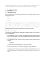
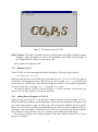
Now, edit the file $HOME/.copsrc.xml. The default file is shown in Figure 1. This file
contains configuration properties used by the CO2 P3 S graphical user interface. Some of these
properties must be filled in before CO2 P3 S can be run. Some can be reset or must be set through
the user interface.
The first part of the XML file consists of header and definition information. You should not
find it necessary to change any part of the first 9 lines (with one possible exception). Lines 1 is
header information regarding the XML file. Lines 2 and 3 are a comment indicating the purpose
and location for this file. Line 4 and 5 indicate where the DTD (Document Type Definition) file
for this document can be found. The DTD file indicates the format of the XML file, including all
legal tags. Since this file is referenced through a URL, your machine must have an active network
connection for CO2 P3 S to work properly. See Section 4.7 for a workaround if you plan to use
CO2 P3 S on a machine that cannot access this URL. Lines 7 and 8 define a name space for the
XML document. CO2 P3 S will work properly if you cannot access this URL.
The region of interest in the .copsrc.xml file starts at line 10 and ends at line 39. The
format of the configuration fields is that of standard XML. Each field starts with the XML tag
4
<?xml version=“1.0”?>
<!- - This is a sample RC file for the CO2P3S program. The location
for this file on the user’s system is $HOME/.copsrc.xml - ->
<!DOCTYPE CopsCfg:copsCfg SYSTEM
“http://www.cs.ualberta.ca/∼systems/DTD/1.0/CopsCfg.dtd”>
<CopsCfg:copsCfg
xmlns:CopsCfg=“http://www/cs.ualberta.ca/∼systems/cops/cfg/”>
10
<CopsCfg:copsInstallationDirectory>
installation path of COPS
</CopsCfg:copsInstallationDirectory>
<CopsCfg:userProgramDirectory>
path to user programs
</CopsCfg:userProgramDirectory>
20
<CopsCfg:defaultEditor>
name of default Java code editor
</CopsCfg:defaultEditor>
<CopsCfg:htmlBrowser>
name of HTML browser
</CopsCfg:htmlBrowser>
30
<CopsCfg:patterns>
<CopsCfg:patternName>Mesh</CopsCfg:patternName>
<CopsCfg:patternName>Distributor</CopsCfg:patternName>
<CopsCfg:patternName>Phases</CopsCfg:patternName>
</CopsCfg:patterns>
<CopsCfg:jiniPolicyDirectory>
install path of COPS/Distributed/JINI/policy/policy.all
</CopsCfg:jiniPolicyDirectory>
<CopsCfg:jiniLUSAddress>
URL for lookup service
</CopsCfg:jiniLUSAddress>
</CopsCfg:copsCfg>
Figure 1: The default XML file that comes with a CO2 P3 S distribution.
5
<CopsCfg:fieldName>
where fieldName is the name of the configuration field. The field ends with the tag
</CopsCfg:fieldName>
where fieldName must match the starting tag. The value of the field is contained between these two
tags. Tags can appear inside of other tags, but they must be properly nested.
The current CO2 P3 S configuration has the following fields:
copsInstallationDirectory This is the path to the CO2 P3 S installation. This field has to be filled
in manually, before CO2 P3 S is run the first time. The correct value for this field is COPSDIR/copsProj. From this point onward, COPSINSTALL refers to this directory.
userProgramDirectory This is the full path of default directory for your CO2 P3 S programs. If
no value is entered or the supplied directory does not exist, your home directory (as defined
earlier in this section) is used. This can be entered either here or through the user interface.
However, because of interface limitations (described in Section 4.7), it should be filled in
before you open or create a program in CO2 P3 S for the first time.
defaultEditor This is the name of your favourite text editor. This editor is used to edit extra
program files that you wish to incorporate into a CO2 P3 S program. This field can be entered
now or entered later using the CO2 P3 S interface. Note that the selected editor must execute
in its own window, as CO2 P3 S will not do this for you. For editors such as emacs and
gvim, this is not a problem. On the other hand, vi does not start its own window. On X11
systems, this can be remedied by specifying
xterm -e vi
as the value of this attribute. You can replace vi with other console–based editors.
htmlBrowser This is the name of your favourite HTML browser. This browser will be used to
display HTML documentation for the design pattern templates in CO2 P3 S. This field can be
entered now or entered later using the CO2 P3 S interface. As with the editor, this browser
must execute in its own window, so browsers such as lynx must be started the same way
that the vi editor is above. However, most of the documentation pages also include graphics,
so a graphical browser is best.
patterns This field contains a list of the current pattern templates that have been loaded into the
CO2 P3 S interface. You should not change this field manually. It will be updated as you
add and remove templates in the interface, as described in Section 2.4.3. This field already
includes entries for the three pattern templates provided with this distribution of CO2 P3 S.
jiniPolicyDirectory This field is for future releases of CO2 P3 S that will include distributed pattern
templates. This field is not used in this distribution, but the field must still appear in the
configuration file. Simply use the current value.
6
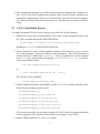
Figure 2: The initial screen of CO2 P3 S.
jiniLUSAddress This field is for future releases of CO2 P3 S that will include distributed pattern
templates. Again, this field is not used in this distribution, but the field must still appear in
the configuration file. Simply use the current value.
Line 39 ends the configuration file.
2.4.2
Running CO2 P3 S
To run CO2 P3 S, use the script supplied with the distribution. This script can be found at
COPSINSTALL/runCops
Right now, this must be executed while your current directory is COPSINSTALL for the images in
the interface to be displayed correctly. When CO2 P3 S is run, a log file cops.log is created in the
current directory. This file logs events and errors in the user interface. If you experience problems,
you can view the log by selecting View Log from the File menu.
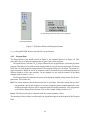
The initial screen for CO2 P3 S is shown in Figure 2. For the remainder of this section, the
menus at the top of the window are the points of interest.
2.4.3
Adding Pattern Templates to CO2 P3 S
When you first start CO2 P3 S, it will have three pattern templates already installed: the Two–
Dimensional Mesh, the Phases, and the Distributor. These three pattern template will appear when
you create a new program or open an existing one. You can use these templates in your programs.
However, CO2 P3 S is an extensible system that allows you to add new pattern templates as they are
developed. Later distributions will include tools to help you create your own pattern templates,
and we hope to create a repository for you to exchange your templates with other users.
The process of adding a new pattern template is best done from the initial CO2 P3 S screen
(Figure 2), as follows:
7
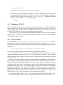
(a) The
menu.
(b) The pattern file selection dialog.
Environment
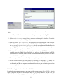
Figure 3: User interface elements for adding pattern templates in CO2 P3 S.
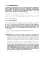
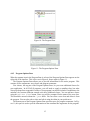
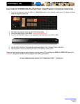
1. Select the Environment menu from the menu bar on the top of the interface. Then select
Import Pattern, shown in Figure 3(a).
2. After you select Import Pattern, the dialog in Figure 3(b) will appear. You use this dialog to select a pattern template to import. By default, this dialog looks for pattern templates
in the directory COPSINSTALL/patterns, which is where the templates bundled with
your CO2 P3 S distribution can be found. If you have downloaded other patterns, navigate to
the directory where you have installed them.
3. Once you have navigated to the appropriate directory, select the XML file for the pattern
template you wish to add. Select it and click OK, and wait for the template to load. This
process can take some time, as the contents of the XML file are used to generate Java source
code which is then compiled.
4. You can repeat the last two steps for all pattern templates you wish to add.
5. As the interface instructs you, quit CO2 P3 S (by selecting Quit from the File menu). The
new pattern templates will be available the next time you start CO2 P3 S. (This is why we
recommend you add new templates from the initial screen, so you don’t interrupt work on a
current program.)
2.4.4
Removing Pattern Templates from CO2 P3 S
If you decide that a pattern template is no longer useful, you can remove it from CO2 P3 S. As with
adding a template, this can be done from the initial CO2 P3 S screen. However, if you do so, you
will not be able to modify any programs that use that pattern template.
8
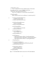
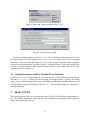
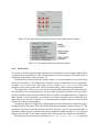
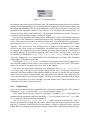
Figure 4: Removing a pattern template from CO2 P3 S.
Figure 5: The Preferences dialog.
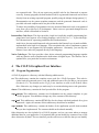
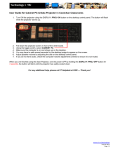
To remove a pattern template, select the Environment menu item from the menu bar at the
top of the interface. From this menu, select Remove Pattern (Figure 3(a)). This is a cascaded
menu item, where the items that appear are a list of the currently imported pattern templates.
Select the pattern template that you wish to remove, as shown in Figure 4. After you confirm your
selection, the pattern template will be removed from CO2 P3 S. It can be added back into CO2 P3 S
using the process in Section 2.4.3.
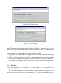
2.5
Setting Preferences with the Graphical User Interface
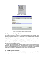
From the Environment menu (Figure 3(a)), you can set your CO2 P3 S preferences at any time by
selecting Preferences. When you select this item, the dialog in Figure 5 appears. This dialog
allows you to set the userProgramDirectory, defaultEditor, htmlBrowser, jiniPolicyDirectory, and
jiniLUSAddress properties described in Section 2.4.1. The remaining properties cannot be set
through this dialog.
3 About CO2P3S
This section describes some of the more general details of the CO2 P3 S parallel programming system. This includes information on the execution environment for your programs and the programming model supported by the tool.
9
3.1 Execution Environment
CO2 P3 S generates multithreaded Java code for the supported parallel design pattern templates.
This code can be run on a uniprocessor or shared memory multiprocessor. On a multiprocessor
system, you can used native threads, which allows the Java Virtual Machine to map the threads to
different processors. This will hopefully result in performance improvements, by using different
processors to execute different parts of your program in parallel.
CO2 P3 S assumes that there is an active network connection. This connection is used to verify
the validity of some of the XML files contained within the CO2 P3 S system. Section 4.7 contains
instructions for removing this dependency if you need to.
CO2 P3 S has no special requirements regarding file systems. Applications that use disk will
need to make sure files are available to all threads that need them. On most shared memory machines, this should not be an issue.
3.2
Programming Model
The programming model for CO2 P3 S consists of three layers of user–accessible abstraction. Each
layer provides distinct abstractions supporting different phases of program development. In addition, each layer gradually exposes more implementation details of the object–oriented framework
code generated by CO2 P3 S, providing openness (which, in this sense, means that you can access
low–level structures and run–time code to improve the performance of your application). More
information on programming in CO2 P3 S can be found in our papers available through the Publications link at
http://www.cs.ualberta.ca/∼systems/cops/index.html
The layers of CO2 P3 S are listed below. The current distribution only supports the topmost
layer. The layers are:
Patterns Layer At this layer, you express the structure of your program by selecting the appropriate parallel design pattern templates. A design pattern template is a design construct that
represents a family of related design pattern implementations. Each implementation has the
same basic structure, but each is a slight structural variation that makes the pattern more
applicable to your specific problem. To select the member of the family that best suits your
problem, you provide values for pattern template parameters associated with each template.
After you have provided appropriate values for the pattern template parameters, you use the
fully–specified template to create an object–oriented framework that implements the selected
pattern structure. An object–oriented framework is a set of (usually) abstract classes that
provide a design and partial implementation of the application–independent part of a specific
kind of application, such as a graphical user interface. In our case, the application domain
is the implementation of a parallel structural pattern. The structural part of the framework
calls a set of hook methods at execution points where application–specific operations are
required. You complete a program by providing implementations of these hook methods by
subclassing the framework classes and overriding the required methods.
For our parallel frameworks, the structural code includes all of the error–prone communication and synchronization code required by a pattern implementation. The hook methods
10
are sequential code. They do not require any parallel code for the framework to operate
correctly. In many programs, the hook method code for a generated framework can be taken
directly from an existing sequential program, possibly using the Adapter design pattern [1].
Documentation on the pattern template parameters and the generated framework code is
provided with each template and is not part of this document.
To reduce the possibility of programmer error, the structural framework code is encapsulated
away from you at this layer of development. Other errors are prevented through the user
interface, which is illustrated in Section 4.
Intermediate Code Layer This layer provides a high–level explicitly parallel programming language based on a superset of an existing language, such as Java or C++. It provides high–
level abstractions for expressing parallelism and synchronization.
At this layer, the structural framework code generated at the Patterns Layer is made available,
implemented in the high–level language. You can optimize the code or implement a pattern
variation that is not supported by the template parameters. Alternately, you can skip the
Patterns Layer and write programs directly in this language.
Native Code Layer This layer provides a base object–oriented programming language together
with any libraries used to implement the abstractions in higher layers. The libraries can be
optimized for your particular execution environment.
4
4.1
The CO2P3S Graphical User Interface
Program Organization
A CO2 P3 S program is a directory with the following subdirectories:
src This subdirectory contains the complete source code for a CO2 P3 S program. This code includes both the generated source code and additional source file you add to your program
(Section 4.4.3). You should use the CO2 P3 S user interface to work on all of these source
files. Otherwise, any changes you make may be overwritten during source code generation.
classes This subdirectory contains the Java bytecode files for the program.
cops patterns This subdirectory contains saved information on the pattern templates in your
CO2 P3 S program. You should not change any of the contents of this directory.
cops html This subdirectory contains HTML files for the classes with hook methods for a given
framework. Again, the contents of this subdirectory should not be modified.
cops methods This subdirectory contains the bodies of the application–specific hook methods
that you have implemented. The contents should not be altered manually.
Other directories are also included in a CO2 P3 S program, and you can create others to manage
additional data for your application. It is important that you not modify the contents of any of the
above directories by hand. The user interface provides safe access to the files that you can modify.
11
Figure 6: The File menu.
Figure 7: The dialog for opening a CO2 P3 S program.
4.2
Opening or Creating a CO2 P3 S Program
The first step in working with CO2 P3 S is to open an existing program or create a new one. These
operations are available through the File menu (Figure 6). The dialog for opening a program is
given in Figure 7.
This dialog starts looking for CO2 P3 S programs in the directory indicated by the userProgramDirectory attribute in your preferences. This is the standard file chooser in Java, and can be
used to navigate your files. The items with the CO2 P3 S logo on the left are directories with a subdirectory structure matching that described in Section 4.1. You can select one of these directories
and select Open to work on that program.
Creating a new program is almost identical. A similar file chooser appears, again starting in
the directory indicated in your preferences. You navigate to where you would like your program
to be kept and enter in the name of the program. The directory for the program, including all of its
subdirectories, is created. The empty program is opened and you can begin work on it.
4.3
Saving a CO2 P3 S Program
Of course, you will want to save the state of your CO2 P3 S programs as you work on them. This
is done by selecting Save from the File menu. It is important to note that this only saves the
12
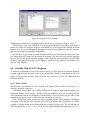
Figure 8: An open CO2 P3 S program.
configuration information of a program, such as the current set of patterns and their values.
Unfortunately, many other changes to a CO2 P3 S program take effect immediately and cannot be
undone by simply not saving the program. You should save your program after making structural
changes to it, or you will find that the program state and the state displayed in the user interface
may not agree when the program is opened later.
For example, if you change a pattern template parameter and regenerate the framework code,
you cannot undo the changes by not saving the program. The next time you load the program,
the code will be that for the modified parameter value while the interface displays the old value.
Similarly, application code is saved as you change it, and will persist regardless of whether or not
you save your program.
4.4
Working With a CO2 P3 S Program
To make the presentation of this section more concrete, we have opened the reaction–diffusion
example programs provided with your CO2 P3 S distribution. Initially it will appear as shown in
Figure 8. This section describes each part of the user interface as well as the compilation and
execution facilities.
4.4.1
Pattern Palette
The first part of the interface we will examine is the Pattern Palette on the left of Figure 8. A
closeup is shown in Figure 9(a).
The Pattern Palette allows you to select from the set of support design pattern templates, represented as buttons on the palette. In Figure 9(a), the templates (from top to bottom) are the
Two–Dimensional Mesh, the Distributor, and the Phases. You can always get the name of the
template by placing the cursor in the button and waiting for the tool tip.
Left–clicking on a button includes the pattern template into the current program. The pattern
will appear in the Program Pane (Section 4.4.2) and in the Pattern Pane (Section 4.4.4). Right–
clicking on a button brings up the background menu, shown in Figure 9(b). You can add the pattern to the program (Insert Pattern) or view the pattern template documentation (Pattern
13
(b) The background menu for the pattern templates.
(a) The Pattern Palette.
Figure 9: The Pattern Palette and background menu.
Help) using the HTML browser specified in your preferences.
4.4.2
Program Pane
The Program Pane is the middle section of Figure 8. An expanded picture is in Figure 10. This
pane shows the set of pattern templates that are part of the current program.
The topmost item, with the CO2 P3 S logo followed by the program name, represents the entire
program. Beneath it is a list of the pattern templates that are used in the current program. Each item
in the list is a small graphical representation of the template followed by its name. The name of a
pattern template is based on one of its parameter values, which allows you to distinguish between
different instances of the same template. In our example, we are using an instance of the Mesh
template with the name RDMesh.
The Program Pane also indicates the status of each pattern template using colours for the template name. The colours are:
Red This colour indicates that the framework code is out of date. This either means that you have
not generated code for this template, or you have changed a pattern template parameter value
and the generated code may not be consistent with the current parameters. You can generate
code from the Pattern Pane (Section 4.4.4) or the Compile dialog (Section 4.4.5).
Green The framework code is consistent with the current parameter values.
The meaning of these colours is indicated by the legend that appears at the bottom of the Program
Pane.
14
Figure 10: The Program Pane.
Figure 11: The Program Options Pane.
4.4.3
Program Options Pane
When the topmost item in the Program Pane is selected, the Program Options Pane appears on the
right side of the interface. This is the case in Figure 8, shown again in Figure 11.
The Program Options Pane allows you to provide information for the entire program. This
consists of two components: user classes and program comments.
User classes, the top part of the Program Options Pane, let you create additional classes for
your application. In all CO2 P3 S programs, you will need to supply a mainline class, but other
classes (perhaps from sequential versions of your program) can also be included. In addition to the
mainline, the reaction–diffusion example uses three additional classes. You can add new classes
using the Add New Class button, where you will be prompted for the name of the new class.
This should be entered without the .java suffix. You can select a user class and delete it from
the program. You can also select a class and edit it using the editor in your preferences.
The bottom part of the Program Options Pane provides space for program comments. In Figure 11, this space is used to provide information on the command line arguments for the program.
15
Figure 12: The Pattern Pane, showing an instance of the Mesh pattern template.
Figure 13: The background menu in the Pattern Pane.
4.4.4
Pattern Pane
If you select one of the pattern template instances in the Program Pane, the Program Options Pane
is replaced by the Pattern Pane for the selected instance of a pattern template. The Pattern Pane on
an instance of the Mesh is shown in Figure 12.
The Pattern Pane shows details on a specific instance of a pattern template, such as the current
values of its parameters. This information is depicted using a combination of text and graphics.
In Figure 12, we can see several class names (RDMesh and MorphogenPair) as well as other
parameter values (a four–point mesh, a fully–toroidal topology, and an ordered computation).
The Pattern Pane is also used to work with the pattern template and generated framework code.
The pane allows you to change parameter values to refine the template, generate code from a fully–
specified template, and insert hook method bodies to complete the implementation of a program.
Some aspects of this functionality are common to all pattern templates and are discussed here.
Other aspects are necessarily specific to a particular pattern template and are covered in more
detail in the template documentation.
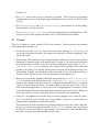
The pattern template is refined using a background menu in the Pattern Pane, obtained by right–
clicking anywhere in the pane. The menu for the Mesh pattern template is shown in Figure 13. The
operations in this menu can be broken down into three categories: generic operations that apply to
all pattern templates, pattern template class names, and pattern template parameters. The latter two
categories are specific to each pattern template and are discussed in the template documentation.
The first menu item in the generic operations, Generate First Layer Code, generates
16
Figure 14: The background menu for the Pattern Pane with multiple viewable templates.
Patterns Layer code from the pattern template using the current template parameter values. If code
is successfully generated, the label for the template in the Program Pane will turn green. The
Generate Next Code Layer item is disabled since this release only supports the Patterns
Layer. It will be enabled in the future when there is more support for the two lower layers in the
CO2 P3 S programming model.
The last menu item in the generic operations, Delete Pattern, deletes the current pattern
and associated files from your program. Note that this deletion takes place immediately and cannot
be undone later.
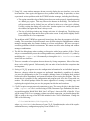
The middle menu item is View Pattern Template. This item allows you to add hook
method bodies to generated framework code, and so is only available when the generated framework code is up–to–date. Selecting this item brings up a Viewing Template window, shown in
Figure 15, that allows you to view and edit hook method bodies for the current framework. If there
are multiple classes in a framework that have hook methods, this item becomes a cascaded menu
item (indicated by an arrow to the right) and you can select the class you wish to edit (Figure 14).
Either a new viewer for the class will appear, or an existing viewer for the selected class will be
brought to the foreground.
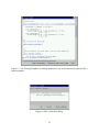
The Viewing Template window is a modified HTML viewer where the links represent places
where you can add or edit code. The code in the viewer is generated with the framework code for
a pattern template, and is run through a code beautifier before being displayed. If you select a link,
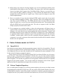
a Code Editor dialog appears, shown in Figure 16.
The Code Editor dialog allows you to modify the code for particular method in the viewer.
This editor is not the one in your preferences, but rather is a dialog that was created specifically to
prevent errors involving hook method signatures. The combination of the Viewing Template and
Code Editor dialogs do not allow you an opportunity to edit the signatures of the hook methods.
Further, the code is generated for you, saving you from having to enter these signatures. This is
important because the remaining framework code relies on the methods in the class in the viewer
having specific signatures for the code to operate correctly. This tool support ensures that these
signatures cannot be changed and prevents some potential compile and logic errors. As an example
of the latter error, consider the first two arguments to the constructor at the top of the code in
Figure 15. These two arguments represent the location in a two–dimensional data structure for
the element being created. If you had to write this signature or were able to change it, you could
accidently reverse the two parameters. This error cannot be caught by the compiler since the
parameter types are correct, which is all the compiler checks. However, the framework code that
uses this constructor is assuming the order in the figure. Reversing the parameters causes the data
to be transposed, which may cause errors later.
In the Code Editor dialog, you can also restore the default implementation of a hook method by
clicking the Restore Default button. This replaces the current value of the hook method with
17
Figure 15: The Viewing Template for editing application code in the framework generated for a
pattern template.
Figure 16: The Code Editor dialog.
18
Figure 17: The Program menu.
the default as generated with the framework code. An important note is that, because of a problem
with the current implementation, the code editor does not display any code for those methods with
the default implementation. The correct method body is still in the actual source code, but is not
displayed in the code editor. However, if you click OK on a code editor with an empty body, you
will overwrite the default with a blank body. This will cause compilation errors later. To preserve
the default, either cancel the change or restore the default.
After restoring the default or accepting a new method body, CO2 P3 S will normally regenerate
source code for the framework to incorporate this new code, and display the updated code in the
viewer. This regeneration can incur an unwelcome time delay. You can disable this regeneration by
unchecking the Regenerate After Each Change checkbox at the bottom of the Viewing
Template. This speeds up the code editing process. Changes to method bodies are no longer
reflected in the viewer. However, the changes are still visible in the code editors. If any methods
are changed, the background of the viewer will turn grey and a label will appear at the bottom of
the dialog, making it is clear that the displayed code is out–of–date. An out–of–date viewer can
be refreshed by rechecking the Regenerate After Each Change. Closing an out–of–date
viewer (by clicking the Close button) will force a code regeneration, so current code will appear
if the template is brought up again later.
Checking the Show Line Numbers checkbox at the bottom of the Viewing Template window cause line numbers for the source code to appear on the left side of the viewer. This feature
allows you to easily find compile errors in the code in this window.
Note that if you regenerate the framework code, using either the Generate First Layer
Code menu item or the option in the Compile dialog (Section 4.4.5), all Viewing Template and
associated Code Editor dialogs for that pattern template are closed. It is possible for you to change
some of the class names in the generated code, which may mean that the class displayed in the
viewer may no longer be part of your program. The best way to ensure that this window always
displays a relevant class is to close it and have you open another viewer, which will always be on
a class that is part of the current framework.
4.4.5 Compile Dialog
Once you have entered all of your application code, you need to compile the code. This is done by
selecting the Compile item from the Program menu, shown in Figure 17.
The Compile dialog, shown in Figure 18, will appear. Selecting Compile will compile you
program with the arguments supplied in the dialog. Clean will remove all of your .class files.
Abort stops any currently executing compilation.
The Regenerate All Layer One Source button performs two functions. First, it
removes all source files (except the user classes entered using the Program Options Pane (Section 4.4.3)), class files, and HTML files for the program. Second, it regenerates source code and
HTML files for all patterns in the program using the current values of the pattern template param19
Figure 18: The Compile dialog.
Figure 19: The Run dialog.
eters. The reason for this is that CO2 P3 S may keep source files that were generated based on old
values of class names. We currently compile all source files in the src directory. However, these
old files can interfere with compilation if the code they contain is out of date. This button lets you
clean out these old source code files. It is also useful for quickly regenerating code for all of the
pattern templates in a program rather than doing it template by template.
Arguments to the compiler can be specified in two ways. Common arguments, for including
debugging information (-g on the command line), deprecation warnings, optimizations, and verbose output can be indicated with the check boxes. Additional arguments can be inserted into the
Flags text field. The output of the compiler will appear in the text area at the top of the dialog.
The contents of this dialog are also saved when you save your program, so you won’t have to
enter this information each time.
4.4.6
Run Dialog
To run your program, select Run from the Program menu (Figure 17). The Run dialog, shown
in Figure 19, will appear.
The Run dialog is much like the Compile dialog. Common options are provided as check
boxes or text areas. Other options can be entered into the Flags text area. The Run dialog has an
20
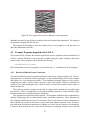
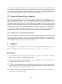
Figure 20: The output of the reaction–diffusion texture generation.
additional text area for specifying the mainline class and command line parameters. The output of
the program is displayed in the text area.
The contents of this dialog are also saved when you save your program, so you won’t have to
enter this information each time.
4.5
Example Programs Supplied with CO2 P3 S
This section briefly describes the example applications that are supplied with this distribution of
CO2 P3 S: reaction–diffusion texture generation, parallel sorting by regular sampling, and matrix
product chain. These programs can be found in the directory
COPSINSTALL/programs
More information on these two programs is provided in the docs subdirectory for the program.
4.5.1
Reaction–diffusion Texture Generation
The reaction–diffusion texture generation problem is taken from computer graphics [4]. The program simulates two chemical, called morphogens, as they simultaneously react with one another
and diffuse over a two–dimensional surface. This simulation repeatedly iterates over the surface,
computing new values, until the values converge to their final solution. When the simulation is
complete, one of the morphogens can be used to render a texture that resembles zebra stripes, as
shown in Figure 20.
This texture is generated so that it can be tiled on a larger surface without any noticeable edges
between tiles. This is accomplished by allowing the diffusion process to wrap around the edges,
both horizontally and vertically, during the simulation.
This program uses the Mesh pattern template. This template parallelizes this computation by
spatially decomposing the two–dimensional surface into distinct partitions. These partitions are
then assigned to different processors for evaluation. However, the nature of a mesh computation is
that each element (or pixel in the texture) requires data from adjacent elements. Thus, each partition needs data from adjacent partitions to compute new values for the elements on its boundary.
Further, for each iteration, the new values for the elements are computed using the values from the
21
previous iteration, which requires barrier synchronization to ensure that no processor computes too
far ahead.
The example program executes the simulation (based on a set of command line parameters that
are explained in the Program Options Pane of the program). The initial, random conditions are
displayed in a window. When complete, the final result is displayed. This window is the only
output of the program. You can use image manipulation software to capture this image for later
use.
To end the program, you will need to kill this window. Otherwise, the Run dialog will still
believe the program is executing.
An interesting note on this program is the reuse of code from the sequential version. All of
the classes in the Program Options Pane except the Main.java class were taken directly from a
sequential implementation of this program. The hook method code is used as an Adapter pattern
[1], essentially translating the interface in the generated framework code to the interface required
by the reused code. In addition to reusing sequential code, this implementation strategy also keeps
the hook method code simple.
4.5.2
Parallel Sorting by Regular Sampling
The second example program implements the Parallel Sorting by Regular Sampling (PSRS) algorithm [2]. This program sorts a specified number of uniformly distributed, random Integer
objects and verifies the results. This is an explicitly parallel sorting algorithm that does not have
a direct sequential counterpart. In addition, this program uses two instances of the Phases and
Distributor pattern templates, providing an example of composing multiple frameworks into a
complete application.
Composing frameworks in CO2 P3 S is simplified because each framework uses the Facade pattern [1] to provide a single, simple interface to the code. The constructor for this Facade creates
all of the objects needed by the framework and assembles them into a complete program, simplifying the instantiation process. The Facade also provides a simple interface for launching the
computation for the framework where applicable (seen in the Phases and Mesh frameworks).
4.5.3
Matrix Product Chain
The final example is matrix chain product, one of the Cowichan problems [3]. This program uses
a dynamic programming matrix to find the least expensive way to multiply a set of matrices. The
program uses a single instance of the Wavefront pattern template, computing the upper half of a
matrix starting from the diagonal and working to the top right corner.
4.6 Disabled Interface Options
This version of CO2 P3 S does not have all options enabled. To minimize the number of changes for
future versions of CO2 P3 S, most of these options are permanently grayed out in this distribution.
These options are:
• The Create or Edit Pattern menu item in the Environment menu. This is provided for future releases that will provide tools for you to modify or create pattern templates
22
(Section 5.1).
• The Tools menu item on the user interface is disabled. These tools are for managing
machines and resources in the forthcoming distributed memory version of CO2 P3 S (Section 5.3).
• The Shared Memory and Distributed Memory radio buttons in the Run dialog.
Shared memory is always selected.
• The Generate Next Code Layer in the background menu in the Pattern Pane. This
release of CO2 P3 S only supports the Pattern Layer, so this menu item is disabled.
4.7
Caveats
There are a number of issues with the CO2 P3 S user interface. These problems, and potential
workarounds where possible, are:
1. You must execute the runCops script while your current directory is COPSINSTALL. If
you run the script from elsewhere, the images in the interface will not be displayed. This
will be fixed soon.
2. When editing hook methods in the Viewing Template window, the code for the complete
framework is regenerated after each method body is accepted. The time for this generation
may be longer than you wish to wait. To prevent this regeneration, uncheck the Regenerate After Each Change checkbox. The window will let you know if the code in the
window is out of date. Note, though, that the most recent code will be displayed in the Code
Editor dialog. It simply won’t be shown in the viewer itself. If you recheck this checkbox or
close the viewer with out–of–date code, the framework will be regenerated.
3. When you regenerate the complete framework, using either the Generate First Code
Layer menu item in the Pattern Pane or the Regenerate All Layer One Source
button on the Compile dialog (but not if you’ve changed a hook method body), all template
viewers and code editors are closed. We cannot check to see if the class in the viewer is
still relevant in the application, or if the correct code is being displayed. Closing the viewers
and reopening them from the Pattern Pane menu ensures that the viewers always display the
most recent version of a class, and that the class is still relevant to the application.
4. Using X11, the graphical user interface may not correctly display over a remote X connection. You will need to run CO2 P3 S on the local machine. As far as we can tell, this is a
problem in the Swing library used for the interface.
This means that you will not be able to use the Run dialog to execute your CO2 P3 S program.
Instead, you can run the program manually. In the classes directory for your program
(Section 4.1) are the class files for your program. You can start the virtual machine using
these files, or copy them to other machines as necessary.
23
5. Using X11, some window managers do not correctly display the user interface, even on the
local machine. Once again, this appears to be a problem with Swing. In particular, we have
experienced serious problems with the FVWM2 window manager, including the following:
• The region around the edge of dialog boxes does not render properly, instead appearing
as a blank grey region. This may obscure the buttons in the dialog. The buttons are
still present and can be clicked, but you will not be able to see what you’re clicking.
Usually, resizing the dialog will correct this. Another option is to iconify and expand
the window, but again this doesn’t always work.
• The size of a dialog window may change each time it is brought up. The dialog may
grow slightly each time until it takes up the entire screen. It may shrink slightly until it
is too small for all of its components.
The problems with FVWM2 are apparently known bugs, but fixes do not appear to be forthcoming. The screenshots for this document were all taken using the Enlightenment window
manager running under the Gnome desktop on a Linux workstation. We have not experienced any problems with this environment. We cannot vouch for other desktop and window
manager combinations.
6. The file list dialog hangs when working on directories with a large number of files. This is
why we recommend that you set the userProgramDirectory attribute (Section 2.4.1), either by
modifying the .copsrc.xml file manually or through the Edit Preferences menu
item in the user interface.
7. There are a number of exceptions that are thrown by Swing components. Most of the time,
these can be safely ignored. Unfortunately, this can make it hard to find the exceptions that
are important.
8. Saving a CO2 P3 S program saves the configuration information for an individual program.
However, changes within the program are performed immediately, regardless of whether
you save the configuration or not. For example, deleting classes or changing hook method
bodies take effect immediately and cannot be undone by not saving the program. This also
means that it is possible for the configuration and program code to be out of step with one
another. We should perhaps follow the emacs approach of creating a working copy and
replacing the original when you save the program, but this has not been done.
9. CO2 P3 S requires an open network connection to start. The reason for this is that the format
of the .copsrc.xml file is verified using a DTD (Document Type Definition) file that is
accessed through the World Wide Web. Line 5 of Figure 1 shows the URL of this file. If you
will be using CO2 P3 S on a computer without a network connection, you should change this
URL to point to the copy of the DTD file included in the CO2 P3 S distribution. Change the
URL to the following:
file:COPSINSTALL/DTD/CopsCfg.dtd
where COPSINSTALL is the directory of your CO2 P3 S installation (the value of the copsInstallationDirectory configuration property from Section 2.4.1).
24
10. When editing code using the Viewing Template, the code for methods that still have their
default bodies will not appear in the Code Editor. The proper code is still in the application
classes, but simply doesn’t appear in the Code Editor dialog. However, you must take care
not to accept an empty window by clicking OK. This overwrites the default with an empty
method body, which will result in compile errors. Either cancel the change or restore the
default implementation.
11. There are a number of cases when the displayed HTML and the actual code do not match.
The most common example is with the < and > operators. These are not displayed correctly
since they are part of HTML tags. The HTML generator does not convert these for proper
display. In other cases, we have seen extra newlines inserted into code. These problems only
affect the HTML and not the underlying code. The code as it appears in the Code Editor
dialog is properly inserted into the source.
12. If no constructors are explicitly added to a class, the code generator will always insert an
explicit default constructor that is not editable by the user. This can be a problem for pattern
designers, as it means that the user cannot augment the default constructor. (Trying to add
the default constructor in user–added code will result in a compile error.) The workaround is
to explicitly add the default constructor as part of the generated framework code and make
it editable. Another option, which is best for constructors that pass arguments to a parent
constructor, is to create a constructor that cannot be edited and that calls an initialize method
that the user can implement.
5
Future Enhancements to CO2P3S
5.1 MetaCO2 P3 S
One drawback to many pattern–based programming systems is their lack of extensibility. The tool
only supports the patterns that the tool developers supply. If a pattern you need for your program
is not supported, then you must either abandon the tool, implement the pattern manually, or wait
for the system developers to support the pattern.
Future releases of CO2 P3 S will include the MetaCO2 P3 S tool that will allow you to become a
pattern designer. If the pattern you need doesn’t already exist, you can create a pattern template
and framework and add it to CO2 P3 S. Similarly, you can correct problems or limitations in existing
pattern templates. You can add new parameters to create pattern variations that were not originally
supported by the pattern template. You can also modify the framework code to better support
applications that the original pattern designer did not consider or to fix bugs.
5.2 Pattern Template Repository
Once we enable pattern designers to create new pattern templates, the next step is to find a means
of exchanging them with other CO2 P3 S users. We can envision a Web–based repository for new or
modified pattern templates. It should be possible to upload new templates, query the repository for
a template that suits your problem, and install that template into your local CO2 P3 S distribution.
25
Even further, if the format of the meta–templates is system–independent, it is possible for other
pattern–based programming systems to take advantage of this repository. Pattern–based tools that
can interpret the meta–template format will find they have a large set of supported patterns that can
solve a broad range of problems. We believe such a format is possible.
5.3 Distributed Memory Pattern Templates
The current pattern templates in CO2 P3 S are targeted at shared memory multiprocessors. Networks of workstations, clusters, or even grid computing systems are also potential targets for
high–performance applications. We are working on versions of our pattern templates that use
Java Remote Method Invocation to execute on these kinds of systems. To make it easier for pattern
designers to create distributed templates, we are also including JINI as a mechanism for managing
remote resources and a library supporting constructs like distribute monitors for synchronization.
Future pattern templates may generate boilerplate code that is required by some grid software
libraries, such as Globus. This will make it easier to take advantage of computational grids.
5.4
Support for Sequential Design Patterns
CO2 P3 S was originally envisioned as a pattern–based parallel programming system. It has become
clear that these same ideas and programming model are equally applicable to creating programs
with sequential design patterns. As we create sequential pattern templates, we will make them
available (hopefully using our pattern template repository).
6
Feedback
We would appreciate any feedback that you have on the CO2 P3 S parallel programming system, or
reports of any bugs that you find. Please send e–mail to [email protected].
References
[1] E. Gamma, R. Helm, R. Johnson, and J. Vlissides. Design Patterns: Elements of Reusable
Object–Oriented Software. Addison–Wesley, 1994.
[2] H. Shi and J. Schaeffer. Parallel sorting by regular sampling. Journal of Parallel and Distributed Computing, 14(4):361–372, 1992.
[3] G. Wilson. Assessing the usability of parallel programming systems: The Cowichan problems.
In Proceedings of the IFIP Working Conference on Programming Environments for Massively
Parallel Distributed Systems, pages 183–193, 1994.
[4] A. Witkin and M. Kass. Reaction–diffusion textures. Computer Graphics (SIGGRAPH ’91
Proceedings), 25(4):299–308, 1991.
26