1
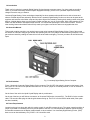
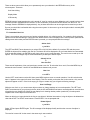
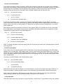
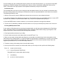
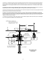
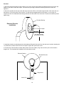
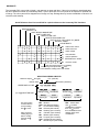
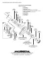
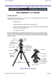
Losmandy Digital Setting Circles
User's Manual
Rev 3.1
Table of Contents
1.0 Introduction. . . . . . . . . . . . . . . . . . . . . . . . . . 2
2.0 About This Manual . . . . . . . . . . . . . . . . . . . . . . 2
3.0 Familiarization . . . . . . . . . . . . . . . . . . . . . . . . 2
4.0 Power Requirements . . . . . . . . . . . . . . . . . . . . . 2
5.0 Initial Setup. . . . . . . . . . . . . . . . . . . . . . . . . . 3
6.0 Alignment Procedures . . . . . . . . . . . . . . . . . . . . 3
6.1 Polar Aligned Scopes . . . . . . . . . . . . . . . . . . . 3
6.2 Alt-Azimuth Scopes . . . . . . . . . . . . . . . . . . . . 4
6.3 Polar-not Aligned . . . . . . . . . . . . . . . . . . . . . . 4
7.0 Operating Losmandy Digital Setting Circles . . . . . . . . . 4
7.1 Setting the Date . . . . . . . . . . . . . . . . . . . . . . 5
7.2 More Basics . . . . . . . . . . . . . . . . . . . . . . . . 5
7.3 Browsing Catalog Objects . . . . . . . . . . . . . . . . . 6
7.4 The Planet Catalog. . . . . . . . . . . . . . . . . . . . . 6
7.5 User Entry of Object Coordinates . . . . . . . . . . . . . 7
7.6 The Menu System . . . . . . . . . . . . . . . . . . . . . 7
7.7 Customized User List . . . . . . . . . . . . . . . . . . . 8
7.8 Search and Identify . . . . . . . . . . . . . . . . . . . . 9
7.9 AZ-EL Display . . . . . . . . . . . . . . . . . . . . . . . 9
7.10 Standby Mode . . . . . . . . . . . . . . . . . . . . . . 9
7.11 Battery Monitor . . . . . . . . . . . . . . . . . . . . . 10
7.12 Realignment on Database Objects . . . . . . . . . . . 10
7.13 Sky Catalogs . . . . . . . . . . . . . . . . . . . . . . 10
7.14 Sidereal Clock . . . . . . . . . . . . . . . . . . . . . . 11
7.15 Use with Equatorial Table . . . . . . . . . . . . . . . . 11
8.0 Specifications . . . . . . . . . . . . . . . . . . . . . . . . 12
9.0 Troubleshooting. . . . . . . . . . . . . . . . . . . . . . . 12
Technical Assistance . . . . . . . . . . . . . . . . . . . . . . 12
Appendices:
A: Determining 90 Degree Setting . . .
B: Serial Communications (RS-232) . .
C: Factors Affecting Pointing Accuracy .
D: Installing the ALT-AZ-1000 kit . . . .
.
.
.
.
.
.
.
.
.
.
.
.
.
.
.
.
.
.
.
.
.
.
.
.
.
.
.
.
.
.
.
.
.
.
.
.
.
.
.
.
.
.
.
.
13
14
16
16
Warranty . . . . . . . . . . . . . . . . . . . . . . . . . . . . 19
Quick Reference Card . . . . . . . . . . . . . . . . . . . . . 19
Equatorial Encoder Installation . . . . . . . . . . . . Back Cover
1.0 Introduction
Thank you for buying the Losmandy Digital Setting Circles telescope computer system. You have made an excellent
choice. If you have not already used a computer equipped telescope, you are in for a pleasant experience that may
change forever the way you observe.
Losmandy Digital Setting Circles are designed especially for those amateurs who would like to be able to locate and
observe celestial objects fast and easily. With the aid of Losmandy Digital Setting Circles more time can be spent at the
eyepiece and less time at the finder scope and sky atlas. Objects are located by entering their catalog number using push
buttons. A digital display shows you the scope's position and lets you 'zero in' on the object. With a little practice you can
locate even the hardest to find objects within seconds. You will find that operating the unit is next to intuitive. This and
other exciting features described herein will help make your nights out under the stars more enjoyable than ever.
2.0 About this Manual
This manual contains everything you need to know to start using Losmandy Digital Setting Circles. Parts of the manual
are written as a tutorial to help you get familiar with operating the unit. Every feature is described using examples. You will
get maximum benefit by reading the manual from front to back without skipping. The time you take to do this will be well
spent.
3.0 Familiarization
Fig 1. Losmandy Digital Setting Circles Computer
Figure 1 shows the Losmandy Digital Setting Circles computer. The ON-OFF slide switch is located on the bottom of the
box. Left is off. The unit can be operated from either the 12 volt DC jumper on Losmandy Mounts, or from an external 12
volt DC power source.
On the front of the unit is the Liquid Crystal Display and six push buttons.
On the top of the box you will find two connectors, an 8 contact RJ45 and a 4 contact RJ11. The RJ45 is for the encoder
cable. The encoder cable plugs in with the gold contacts facing up. The RJ11 is for the RS232 serial cable (if the option
has been installed).
4.0 Power Requirements
Located on the top is a phono jack which is used to supply 12 volts DC to power the unit. The center contact is positive. A
jumper is provided on Losmandy mounts to provide power to the DSC. For cold temperature operation (below freezing),
an internal thermostat turns the display module heater on when needed. Your Losmandy Digital Setting Circles, (DSC)
does not use an internal battery. Only 12VDC +-10% should be used.
2
5.0 Initial Setup
There are two parts to the initial setup. First you choose the mount type (Fork, German Eq, or Dobsonian). Second, you
will set the resolution (number of steps/rev) and direction of the encoders.
Turn the unit off. Press in and hold both the up and down arrow buttons, then turn the unit on and release the buttons. Use
the LEFT or RIGHT arrow buttons to select either FORK, DOB or GERMN. For Dobsonians, select FORK for now (you
will change it to DOB later). Press the ENTER to save the selection. Press the DOWN arrow until you see the RA
ENCODER RESOLUTION display. Use the arrow buttons to set the number of encoder steps (4096 nominal). Press
ENTER to save. Now press DOWN to get the DEC ENCODER RESOLUTION display. Change this one in the same way.
Now turn the unit off. Your selection will be retained even without battery power. You can verify the setting at any time by
repeating the above procedure.
NOTE: Even though encoder resolutions up to 32767 are valid (higher values are NOT valid) such a high resolution would
require that the telescope be moved VERY slowly to avoid encoder 'skipping' or missed steps.
Turn the unit on. Press ENTER to accept the date. In a few seconds a prompt will be displayed asking you to select either
1 or 2 star alignment. For the purpose of initial setup, press UP for 1-star alignment. A second message will prompt you to
select an alignment star from a list of 41 stars. Position the scope near 0 degrees declination (horizontal for DOB mounts).
If your mount is a German Equatorial, position the scope to point to the East side of the meridian. If your scope is fork
mounted, position the fork as you would for observing a star near the equator. Be sure that the side of the fork that is now
facing up is the same side that you would use normally.
Now select a star from the list that is not too far from the equator. The UP and DOWN arrow buttons let you review the list.
Press the 'E' button to select. The top line of the display will now show hours and minutes of R.A. and degrees of
declination. Note that the UP arrow button will turn on and off the asterisk (*) symbol in the top left of the display. Leave
the * off.
While watching the R.A. on the display, move the scope slowly in the Easterly direction (CCW For Dobsonians). The R.A.
should increase. If it decreases instead, just note the fact and continue.
Move the scope slowly in the Northerly direction (UP for Dobsonians). The declination readout on the display should
increase. If the direction is wrong, make a note and continue.
If both R.A. and declination readouts are consistent with the motion of the scope, then nothing more needs to be done. If
either or both readouts change in the opposite direction to the way the scope was moved, then continue to the next
paragraph.
Turn the unit off. Press and hold both the UP and DOWN arrow buttons. Turn the unit on and then release the buttons.
Press the DOWN arrow button once and the display will show you the current setting for the direction of the R.A.
(Azimuth) encoder, either NORMAL or REVERSED. Press DOWN again to see the same information for the Declination
(Elevation) encoder. The LEFT and RIGHT arrow keys let you change the direction of either encoder. Make the required
changes and then press the ENTER key to save those changes. If ENTER is not pressed, the changes will not be saved.
Now turn the unit off and repeat the procedure to make sure that the encoder directions are now correct. This completes
the initial setup.
If the scope is a Dobsonian or Alt-Azimuth, repeat the part where you select FORK DOB GERMN, and select DOB. Press
ENTER to save it.
6.0 Alignment Procedures
Each time the Losmandy DSC is turned on, you must go through an alignment procedure so that the computer has an
orientation to the sky. The Losmandy DSC supports two alignment methods called 1-Star and 2-Star. The procedure you
use depends on the type of mounting your scope has and the accuracy to which it is polar aligned. If the scope is very
well polar aligned, only one reference point (star) is needed. However, if polar alignment is only rough or the mounting is
Dobsonian, then two reference points (stars) are needed. In that case, see section 6.2 on Alignment for Alt-Azimuth. Note
that anytime polar alignment is in question a 2-Star alignment can be done.
6.1 Polar Aligned Scopes
This section describes the 1-Star alignment that can be used on mounts that have been well polar aligned. The 1-Star
alignment is the easiest of the two procedures since it requires only one sighting. The positioning accuracy of your system
however will depend on the accuracy of the polar alignment.
3
When the Losmandy DSC is turned on, select 1-Star alignment with the UP arrow button. The display will show 'Sight 1st
Star' on the top line. The bottom line will show the name of one of 41 'alignment stars' along with it's magnitude. The UP
and DOWN arrow buttons let you select the star you are going to use. If you have a German Equatorial (NOT FORK
MOUNT) mount and you want to use a star in the Western sky, use the LEFT and RIGHT arrow keys to change the
display to 'Sight 2nd Star'. For fork mounts leave the display at 'Sight 1st Star' for any alignment star, East or West of the
meridian.
Sight the star with your scope. Get it as close to center of field as possible. When the star is centered, press ENTER. This
completes the alignment procedure. Now go on to read section 7, Operating the Losmandy DSC.
6.2 Alt-Azimuth Scopes
One of the most useful features of the Losmandy DSC is it's ability to operate on Alt-Azimuth type mounted telescopes
(Dobsonian). As you may already be aware, conventional type setting circles cannot be used on Alt / Az mounts.
To use the Losmandy DSC on an Alt-Azimuth mounting, a 2-Star alignment must be done every time the unit is turned on.
The procedure is similar to the 1-star alignment described above except that two star sightings are done.
The two star alignment starts out with 'Sight 1st Star'. Use the UP and DOWN arrow buttons to select a convenient star.
The first one in the list is Polaris. This is usually a good star for Northern hemisphere users.
Sight the star with the scope. Be as accurate as possible. Press ENTER when you have the star sighted.
The display will now show 'Sight 2nd Star'. Select another star. Try to pick one about 90 degrees from the first star if
possible. Avoid using stars close to the zenith or very close to the horizon. The effects of atmospheric refraction, though
small can contribute to the overall pointing error.
[Note: The computer will allow you to select any of the 41 available alignment stars. It is up to you to choose ones that are
suitable. Suggestion: Mark the 41 stars on a planisphere for a handy reference. Also choose your alignment stars ahead
of time.]
Sight this star just like the first, then as press ENTER. You have just completed the alignment procedure. Now go on to
read about operating the Losmandy DSC.
6.3 2-Star Alignment with Polar Mounts
Sometimes it is not convenient to polar align accurately but you still want to be able to find objects. When you are
prompted for 1 or 2-star alignment, select 2-star. You will be prompted to set the scope to +90 degrees. This means
relative to the scope, not the sky. For instance, if the scope is on a fork mount, it should be positioned parallel to the fork
arms. For a German Eq, the scope should be parallel the polar shaft.
For fork mounts, this positioning is not very critical (within a degree or so is fine). If the mount is a German Eq, you must
set this position with some accuracy. See the Appendix A which describes a method for determining the +90 degree
position for a German equatorial.
Next you will be prompted to sight the 1st star. Use the UP and DOWN arrow buttons to select a convenient star on the
Eastern side of the meridian. Get the star sighted accurately in the scope and press ENTER. Now you will be prompted
for the 2nd star. Choose one on the Western side of the meridian (preferably about 90 degrees from the first). Again, sight
the star and press ENTER.
For fork mounts best results are obtained by using stars well north of the equator (but not Polaris).
7.0 Operating the Losmandy DSC
All of the Losmandy DSC functions are accessible through the six button keypad array on the front panel. The buttons are
arranged in such a way to make them easily located by feel. The two buttons on the right and arranged vertically are the
UP and DOWN arrow buttons. the remaining four buttons on the left are arranged in a square. The two top buttons are the
LEFT and RIGHT arrow keys. The bottom buttons (left to right) are ENTER and MENU.
In normal operation the keypad buttons are pressed and quickly released, like dialing on a touch-tone phone. If the
buttons are held down for a prolonged period however, multiple presses of the button are generated. This can be
convenient when there is a long list of items to view.
4
7.1 Setting the Date
Each time you turn on the Losmandy DSC you are shown a date on the display. The date is used in the calculation of
planet positions. You can change it by simply moving the cursor with the RIGHT arrow button and scrolling the month, day
and year with the UP and DOWN arrow buttons. Pressing ENTER causes the date to be set. The date is not driven by a
'real time' clock as in a desktop PC; you always have to change it manually if you want the planet positions to be correct.
7.2 More Basics
This section takes you step by step through the basic operation. It can be done indoors since the main purpose is to get
you familiar with using the buttons. For simplicity, a one star alignment will be done. If you have a Dobsonian, change the
setup to 'FORK'. Just pretend for now that it is polar aligned (as if you were at the North pole for instance). Remember to
change back to 'DOB' when you have finished this section.
Turn the unit on and wait for the '1-2 Star Align?' prompt. Press the UP arrow to select 1 star. Now use the DOWN arrow
button to select the star Mirach in Andromeda. Mirach is at 1h 10m, 35.6 North. Move your scope to approximate that
position, then press ENTER to complete the alignment. [NOTE: If you have mechanical setting circles you can use them
to position the scope. Rotate the RA circle to put 1 hour on the meridian for convenience.]
The top line of the display will now show hours and minutes of R.A. and degrees of declination. This corresponds to the
alignment star. Be aware that the sidereal clock in the computer is running and if the scope is not being driven in RA, the
display readout will increment automatically. Move the scope slowly in RA and declination and watch display readout
change accordingly.
The bottom display line will shows the name of the default celestial object with the constellation it's in:
01h 10m +35.6
Mes_0031 AND
The Messier catalog is the default catalog (there are 10 catalogs) and M31 is the first Messier object East of 0 hours.
Therefore M31 is always the default object. Remember, the display shows the position of the scope, not the object.
To locate the displayed object with the scope, press the UP arrow button. Notice that it turns on an asterisk symbol (*) on
the top line. Also notice that when the * is on the numbers for R.A. and declination are different. When the * is off, the
readout is showing the absolute position that the scope is pointed to. When the * is on the readout shows the relative
position of the scope to the object. The scope can then be moved to 'zero' the display. Move the scope now to make the
display look like the following:
* 00h 00m 00.0
Mes_0031 AND
With all digits reading zero, the scope is then pointing to M31, the Andromeda galaxy. Press the UP arrow button once
more to go back to absolute coordinates (00h 43m +41.2). This also happens to be the coordinates of M31!
One word about the relative position display: It is possible for the scope to be more than 99.9 degrees in declination from
the selected object. Example: Scope is at +90 and object is well south of the equator. The display only shows three digits
in declination however. Therefore readings larger than 99.9 (+ or -) are not displayed. While the scope is more than 99.9
degrees form the target, the display shows just 99.9 and will not change until you move the scope close enough.
For each object in the data base (you will learn how to get to other objects in a moment) there is information that can be
displayed. Press the DOWN arrow button and see the following:
00h 43m +41.2
Galaxy +03.5
The +03.5 is the visual magnitude.
Press the DOWN arrow again to return to the previous display.
The Losmandy DSC stores information on over 9000 Celestial objects. To access them you will use the four arrow buttons
and the ENTER button. Notice the cursor (underline symbol) between Mes and 0031. The LEFT and RIGHT arrow
5
buttons control the position of the cursor. Press the LEFT arrow now and the cursor will move under the M in Mes. At this
point the function of the UP and DOWN arrows changes to allow you to access catalogs other than Messier. Press the
DOWN arrow and the NGC catalog pops up. Keep pressing DOWN to get other catalogs:
IC, UGC, Double Stars, etc. The UP arrow lets you go through the list in reverse.
Go back to the Messier catalog now. Use the RIGHT arrow to position the cursor under the 3 in 0031. The UP and DOWN
arrows now let you change the digit. Select Mes 0051 for instance. Press ENTER and the computer will bring up M51 the
Whirlpool galaxy from it's data base. The cursor is automatically returned to the 'home' position (between Mes and 0051).
The UP and DOWN arrow buttons now return to their original assignment of toggling the top and bottom display line
information. [NOTE: if ENTER is pressed when the cursor is in 'home' position, the display will prompt you with 'Add to
List?'. Just press ENTER again to remove the message. The User List feature is covered in section 7.7.]
Whenever an object number is entered which does not exist in the data base, an error message is displayed briefly:
'Object Not Found'. Then the last valid object number is redisplayed.
The Double Star catalog works just a bit different than the other catalogs. Position the cursor to the far left and then index
to the Double Star catalog (DBL). Since many double stars have names instead of numbers, it is not possible to have
them cataloged numerically. Therefore they are cataloged by constellation instead. The display will be similar to the
following:
00h 43m +41.2
DBL OΣ 514 AND
Move the cursor to the right until it appears under the first letter of the constellation. Now use the UP and DOWN arrows
to index through the constellations. The constellations are in alphabetical order. Since there are a large number of
constellations (88) you can hold down the button to quickly scroll through the list. Also, the list of constellations wraps
around so that if you need to get from Andromeda to Vulpecula you only need to press the UP arrow once!
When you get to the constellation you want, move the cursor over to the left under the first letter of the double star name.
Now you can browse through the list of double stars for that constellation with the UP and DOWN arrows. Keep an eye on
the constellation name as you browse because when you reach the end of the doubles in that constellation, you will
continue on with doubles in the next alphabetically listed constellation.
For double stars, the information given is magnitude (primary/secondary) and angular separation. Example: select 24 in
Andromeda. Press the DOWN arrow to see info on 24. Line 2 of the display should look as follows:
7.6/8.4 005"
24 AND is a 5 arc second double with primary visual magnitude 7.6 and secondary magnitude 8.4.
Now you know how to access the thousands of deep sky objects and double stars that are stored in the computer's
memory. You are well on your way to becoming an expert Losmandy DSC user.
7.3 Browsing Catalog Objects
You can specify a constellation and browse through the cataloged objects. Index to one of the deep sky catalogs (Messier
or NGC). You will notice a diamond symbol just to the left of the constellation name. Position the cursor under the
diamond and then use the UP/DOWN buttons to scroll through objects. As you scroll, the description of the object will
appear first for one second. Then the catalog and number will be displayed. This is to give some quick information about
the object so you can decide if it of interest to you. Now move the cursor under the constellation name and use the
UP/DOWN button to select a different one. NOTE: Objects which appear while browsing in this way are pre-qualified by
the LIMIT SEARCH MAG setting. LIMIT SEARCH MAG is discussed in section 7.8
7.4 The Planet Catalog
Planets can be located just like any other cataloged objects. In order to be able to find them using the Losmandy DSC
however, the date must have been set correctly. For the Western hemisphere, it is best to use the date of the following
day since 0 hours Universal Time is assumed.
Index to the PLN catalog using the arrow buttons. You can then position the cursor under the planet name and change it.
Zero-in works the same as always.
6
7.5 User Entry of Object Coordinates
You will notice that one of the catalogs in the list is identified by the letter 'S'. It is a Special catalog in which you can enter
the coordinates of up to 59 objects such as comets or asteroids. Proceed as follows:
Move the cursor to the two digit ID just to the right of the S. The UP and DOWN buttons let you select the object ID
number. Move the cursor to the right again and enter the Hours and minutes of RA. Do the same for declination. Press
ENTER to save the coordinates. This can be repeated for each of the 59 locations.
You can now 'zero in' to any of your special objects by selecting the ID number and then turning on the '*' symbol.
There is no way to enter any object description; there is only the ID number (0 to 58). Therefore it is a good idea to keep a
written list of what these objects are.
7.6 The Menu System
As mentioned earlier, there are additional features that are accessible through the keypad. Each has a special display
screen called a menu. This section describes the menu system and how to use it. By reading through these next few
paragraphs and trying the examples, you will become familiar with the way menus work. You will find it easy and
convenient. Don't concern yourself with the details of the features themselves right now, they are described in later
sections.
The MENU button puts the menu screens on the display. Press it once and see one of the following menus displayed:
1. Search-ID
2. Limit Search Mag
3. Display Mode
4. LCD Intensity
5. User List
6. Battery Monitor
7. Realign on Obj
8. Equatorial Table Reset (only for DOBs)
Now press MENU again and see that you are returned to normal operation (coordinates on top line, object or data on
bottom line). The MENU button is dedicated to getting back and forth between normal operation and the menu screens. It
can be used at any time (except during initial alignment).
[ NOTE: If the MENU button is pressed twice in quick succession, the unit will go into standby (light off). Press any button
to return to normal operation. Section 7.10 covers standby mode]
Return to the menu screen and try pressing the UP and DOWN arrow buttons. The other menu items are displayed in
sequence. For now, don't worry about what some of these menus control. This will be covered in detail later. Note that for
each menu (except battery monitor), the bottom line contains selections, e.g. ON/OFF. In most cases the cursor (underline
symbol) identifies the current selection which is also highlighted in capital letters. Arrow symbols appearing to the far left
and right indicate that the LEFT and RIGHT arrow buttons are used to change the selection. Try going to the LCD
intensity menu (use UP or DOWN arrow buttons to get there). Now use the LEFT and RIGHT arrow buttons to increase
and decrease the LCD backlight. See how easy it is?
When you are satisfied with your selection and have no need to change any other menu item, press the MENU button and
you are returned to normal operation. Be aware that some menus enable special functions, so for now leave the ON/OFF
items OFF.
7
There are three menus which allow you to permanently save your selection in the EEPROM memory of the
microcomputer. These are:
Limit Search Mag
Display Mode
LCD Intensity
EEPROM memory is not lost when the unit is turned off, even for months or years. When the unit is turned back on, those
selections saved in EEPROM will be restored. To save a selection you press the ENTER button from the menu. The
message 'Saved to EEPROM' is displayed briefly. Any of these three items can be changed and re-saved as you wish.
By now you should feel comfortable with using the menu system. It's time now to go on and explore other Losmandy DSC
features in detail.
7.7 Customized User List
There is a convenient way to access your favorite celestial objects. It is called a user list. You create the list by selecting
objects from the internal catalogs. It works like this: Whenever the cursor is displayed in the 'home position' (between the
catalog name and number) and the ENTER button is pressed, you are prompted with the message:
Add to List?
< yes NO >
The LEFT and RIGHT arrow buttons let you select YES or NO. NO is the default. If you select YES and then press
ENTER the object will be added to the user list. The letters OK will be displayed to let you know that the item was added.
If NO is selected (default), the ENTER key will simply return you to normal operation. The user list can contain up to 120
objects. Two error messages may be encountered when you attempt to add an object:
Already in List
or
User List Full
These are self explanatory. Now you know how to create a user list. To review the list or use it, Press the MENU key to
activate the menu screens. Use the UP and DOWN arrow buttons until you see:
User List
< on OFF >
Use the LEFT arrow button to select ON, then press MENU again to return to normal operation. You will notice that the
letter 'U' appears in the upper left corner of the display. This is to remind you that the user list is turned on. Only user list
objects will appear on line 2. If the list is empty (you forgot to create one) you will get the following message:
User List Empty
While the user list is on, you cannot enter object numbers or change catalogs as in normal operation. The LEFT and
RIGHT arrow buttons let you go through the list, while the UP and DOWN arrow buttons are assigned their usual function
of toggling the two display lines. When the top display line is showing relative position (asterisk on) it is always with
respect to the current object on the bottom line.
When an object is no longer desired in the list you can delete it. With the list turned on, bring the object to be deleted into
view with the LEFT or RIGHT arrow buttons. Press ENTER. You are prompted with:
Delete Object?
< yes NO >
Select YES and press ENTER again. The OK message will be displayed briefly and then the next user list object is
displayed.
The user list is turned off via the menu in the same way it was turned on.
8
7.8 Search and Identify Mode
In the Search and Identify mode the computer is continuously searching it's data base for any object whose coordinates
match those of the telescope. Whenever an object is found to be within .5 degrees of the telescope's position, the name of
the object pops up on the display. This is a convenient way to identify an unknown object which may be found while
scanning visually with the telescope. Search/ID mode is enabled or disabled with the Search/ID menu:
Press: M
(to get to menu screens)
5 or 6 (to get to Search/ID)
3
(to turn on search)
M
(to get to back to operating mode)
If no objects are found to be within .5 degrees, the message "Searching Data" appears on the display. The memory
search is executed so quickly that object names may appear on the display and then disappear quickly as the telescope is
slewed. If there is more than one object within the .5 degree circle, the closest one will be displayed even if it is dimmer
than the farther one.
Many objects in the deep sky catalogs are as faint as 17th magnitude. Often it is not possible to see such a faint object
due to small aperture or city sky glow. At such times it is desirable to pre-qualify objects based on magnitude. An upper
magnitude limit can be set with the 'Limit Search Mag' menu:
Press: M
(to get to menu screens)
5 or 6 (to get to Limit Search Mag)
3 or 4 (to adjust magnitude limit)
E
(if desired to save limit in EEPROM)
M
(to return to normal operation)
NOTE: The Search and Identify mode uses battery power at over two times the normal rate. It should therefore not be left
on for long periods.
7.9 AZ-EL Display Mode
If your scope is on an Alt-Azimuth mounting such as a Dobsonian, you will want to take advantage of the AZ-EL display
capability of the Losmandy DSC. AZ-EL display mode is turned on and off through the 'Display Mode' menu. AZ-EL mode
changes the way the coordinate readout is displayed while the asterisk (*) is showing on line 1 (zero-in mode). While AZEL is on, the display shows the scope's position relative to the selected object on line 2 in AZimuth and ELevation instead
of R.A. and declination.
Try turning on the AZ-EL display mode. Use the following steps:
Press: M
(to get to MENU screens)
5 or 6 (until you get 'Display Mode')
6
(to select AZ-EL)
M
(to exit MENU screens)
Notice that the UP arrow button still toggles on and off the asterisk (*) symbol in the top left of the display. When the * is
turned on the display is showing the relative position of the telescope to the selected object in azimuth and elevation.
AZ-EL mode is very desirable for Dobsonian type scopes. When you are zeroing in to the target, the azimuth offset
(display reading) is affected only by movement in azimuth. The same is true for elevation.
7.10 Standby Mode
There will be times when you are not actively using the computer. At such times it is a good idea to put the unit in standby
9
to save battery power. Standby is activated by a double press of the MENU button (two presses in quick succession).
You will first see 'Standby Mode' on the display and then the display light will go out. Standby extends battery life by
about 50%.
During standby the scope may be moved as in normal operation. To resume operation, just press any button once.
Standby can be used to turn off the display light if it becomes bothersome. When you are done observing for the night,
make sure that the unit is turned off and not just in standby.
7.11 Battery Monitor
To see the battery monitor, first press MENU to get to the menu screens and then use the UP and DOWN arrow buttons
until you see the bar graph on the bottom line. A full charge is indicated when the bar extends all the way from left to right.
As the battery is used, the bar will shrink until it disappears, indicating that the battery needs to be replaced. It is easy and
convenient to check the battery before leaving home for your favorite observing site.
7.12 Realignment on Data Base Objects
Due to a number of factors the pointing accuracy may not always be as good as the encoder resolution of .09 degrees.
The Realign on Object feature can be used to make up for pointing errors. To realign on any database object, do the
following:
Press: M
(to get to menu screens)
5 or 6 (to get to Realign on Object)
Sight the currently selected object in the scope. Make sure you have correctly identified the object and center it as
accurately as possible.
Press: E
(to realign)
'OK' is displayed. You are then returned to normal operating mode. As long as you are working this part of the sky, you
should have excellent accuracy. If you move to a different part of the sky you may want to realign again.
7.13 Sky Catalogs
There are 12 varieties of catalog types in the data base. A one to three character catalog code appears on the very left of
display line 2 when the object number or name is being displayed.
Here is a list of those codes with the meaning for each:
Mes: Messier (all types of objects)
NGC: New General Catalog (all type objects)
IC : 1st and 2nd Index Catalogs
Brd: Barnard - dark nebula
Brk: Berkeley - open clusters
Clr: Collinder - open clusters
Mel: Melotte - open clusters
Trm: Trumpler - open clusters
UGC: Uppsala General Catalog
DBL: Double Stars
S : For entry of RA and DEC coordinates
PLN: The major planets
10
For each catalog type, the Losmandy DSC keeps a pointer to the object last referenced. e.g. if you enter the object M27
and then go to the NGC catalog to find something else, when you return to the Messier catalog, M27 will be current.
NOTE: in Search/ID mode object pointers will be updated automatically as objects are identified.
7.14 Sidereal Clock
The Losmandy DSC has a built in clock to keep pace with the apparent motion of the sky. Normally it is desired to have
this clock running, however if the telescope is a Dobsonian on top of an equatorial table the clock needs to be turned off.
The following procedure is used:
1. With the unit turned off, press the DOWN arrow button then turn the unit on (now release the button).
2. You will see "Sidereal Clock" displayed on the top line. The bottom line shows you the ON/OFF selection. Use the LEFT
and RIGHT arrow buttons to select the desired state of the clock (OFF for equatorial table operation).
3. Press the ENTER button to save the selection. You must do this, otherwise no change will be effected.
4. Turn the unit off. Hereafter the sidereal clock will be either on or off (as you selected) every time the unit is turned on.
7.15 Using With Equatorial Table
If your scope is a Dobsonian and you are using an equatorial table, you will want to take advantage of the Table Reset
menu. This feature allows you to reestablish alignment after resetting the table without having to go through the 2-star
alignment procedure. Use the following setup and alignment procedure:
1. Polar align the table to the best of your ability.
2. Check to make sure that the unit's sidereal clock is turned OFF (see 7.10).
3. When you are ready to do the initial 2-star alignment, turn the table on and then bring it to the reset position. At the
same time turn the Losmandy DSC on. These two operations should be done simultaneously or as nearly so as possible.
If you turn the unit OFF and ON to accomplish this, make sure that it is off for at least 2 seconds. Perform the 2-star
alignment (as described in 6.2). You are now ready to observe.
4. To assure accuracy of the setting circles, leave the table running.
5. At some point it will be necessary to reset the table. When you are ready to do this, perform the following steps:
Press: M
(to get to menu screens)
5 or 6 (to get to Equatorial Table Reset)
Bring table back to reset position (table running).
E
(immediately)
M
(to return to normal operation)
11
8.0 Specifications @25C unless noted
PARAMETER
CONDITIONS
SPEC
Operating Voltage
5.5 to 13.8 VDC
Supply Current
Scope stationary or moving slowly
10 mA typical
Display Heater Current
Operating 12VDC Ext.
120mA
Encoder Type
Max Rotational Speed
Optical Rotary, 4000 step standard,
supports up to 32767
150 mech. deg/sec max.
w/4000 step encoders
Operating Temp
0 to 50C internal battery/ no heater.
-25 to 50C external 12v power w/heater.
Displayed Resolution
1 min RA, .1 deg dec, RA/dec
.1 deg AZ, .1 deg el, AZ-EL
Display Type
2x16 char high contrast super twist LCD,
yellow/green backlight. Adjustable intensity.
Serial Port
300 to 38.4k baud 1 start bit, 8 data bits,
no parity, 1 stop bit.
Compatible with: The Sky, Megastar,
Guide and others.
9.0 Troubleshooting
Your Losmandy DSC computer was checked out fully before shipping. Should you experience difficulty,
please refer to the following trouble chart before calling for assistance.
TROUBLE
CORRECTIVE ACTION
No display indication when unit is turned on.
Check external 12V power and connection.
No display backlight visible.
Adjust intensity with keypad. Light is intentionally dim for
night use.
Either RA or dec readout does not change when
scope is moved.
Check connections to encoder. Yellow wire goes to ground
pin. Try switching encoders to isolate problem.
Objects cannot be found.
Check direction and resolution settings for each encoder.
Objects may be too dim. Be sure to correctly identify
alignment stars.
Position accuracy poor.
Check resolution setting for each encoder. Check
centering of encoders. Check orthogonality of axes and
optical collimation. Center alignment stars accurately.
Position accuracy degrades with time.
Check that the sidereal clock is running (section 7.14).
Check encoders to make sure they are not slipping. Do
not move scope too fast.
RA or Azimuth reading seems to stop counting
when turning scope counter-clockwise, but may
be OK in clockwise direction.
Azimuth pivot pin may not be tightly secured to ground
board. Retighten. Pivot pin may be binding if not mounted
perpendicular. Pivot pin may be too short, causing binding.
Try to remount. Use lubricant on pin/bushing if necessary.
Technical Assistance
Technical assistance is available to all customers free of charge.
Please use the following numbers: TEL: 323-462-2855
FAX: 323-462-2682
Leave message if necessary.
Send E-mail to : [email protected]
Or write to:
Hollywood General Machining, Inc.
1033 N. Sycamore Avenue
Los Angeles, California 90038
12
Appendix A
Method of Determining 90 Degree Setting
The utility of the 2-star alignment is in not having to be polar aligned. Whenever a 2-star alignment is done, the user is
required to orient the scope to '+90 degree declination' (except for Dobsonians). It is important to understand that this
position is relative to the telescope itself and not the sky. The 90 degree position is achieved by having the optical axis of
the scope parallel to the scope's polar axis.
The Losmandy DSC computer uses a unique Auto-Lock method whereby the +90 degree point is found by computation
based on the sighting of the two alignment stars. You are only required to set the position to within about a degree or so.
Thus, one opportunity for error is eliminated. Auto-Lock applies only to fork mounted scopes. It does not apply to German
equatorials. This means that the +90 degree setting must be done with some precision for a German equatorial.
Fortunately there is an easy method to locate the +90 degree point on a German equatorial.
Perform the following steps:
1) Collimate the telescope as accurately as possible.
2) Position the scope with the polar axis pointed toward Polaris (not the actual celestial pole). Polaris is used because is
relatively stationary.
3) Put the scope in top position (dec axis vertical as viewed from front). Adjust the elevation of the mount so that Polaris
passes through the center of field as the scope is moved left and right on the dec axis. Use a medium power eyepiece
(preferably one with an illuminated reticle).
4) Now put the scope in side position (dec axis horizontal) on the west side of the mount. Adjust the mount left and right
until Polaris moves through the center of field as the scope is moved up and down on the dec axis.
5) Flip the scope to the opposite side of the mount (dec axis again horizontal). See how close Polaris comes to center of
field as you sweep on the dec axis.
6) If Polaris cannot be centered, it means that the optical axis is not square with the dec axis. Shim the optical tube as
required to correct the error. Take up just half the error as seen in the eyepiece, otherwise you will be off in opposite
direction when you flip the scope to the other side. You will have to make a small azimuth adjustment as well each time
you adjust the shim. Repeat steps 4-6 until Polaris is centered on both sides of the mount.
7) Bring the scope to top position once more. Move on the dec axis to bring Polaris to the center of field. If it is a little high
or low, don't worry but make sure it is centered left to right.
8) Now adjust the mechanical declination setting circle to exactly 90 degrees and lock it down well. If there is no
mechanical setting circle, some means should be employed to locate this exact position when it is needed.
13
Appendix B
RS-232 Serial Communications
The 4 contact RJ11 connector on the back of the box is for connecting the Losmandy DSC to a PC or other computer
device. For connection to a PC, the serial port (COM1 or COM2) is used.
Several commercially available programs for the IBM PC interface with the Losmandy DSC. These programs allow you to
display a section of the sky centered on the position of the telescope. This can be convenient when hopping from one
object to others nearby. In addition to commercially available programs, SkyView, a graphics shareware program is
provided free of charge.
Some users may wish to write their own programs to interface with the Losmandy DSC. For this you will need to
understand the data format that is used.
The protocol for the bus is: 1 start bit, 8 data bits, no parity, 1 stop bit. Baud rate is selectable from 300 to 38.4k baud.
Whenever the program needs updated coordinates it sends a [CR] character ($0D) to the Losmandy DSC on the RX data
line, (pin3). The program should immediately prepare to receive a 16 character ASCII string. Polling should be limited in
frequency to once per second. Xon/Xoff is not supported. The format is as follows:
[1] space
[2,3] integer part of RA hours
[4] fixed decimal point
[5-7] fractional part of hours
[8] space
[9] + or - for declination
[10,11] integer part of declination
[12] fixed decimal point
[13-15] fractional part of declination
[16] NULL character to terminate string
Example: _12.345_+67.890 (underscore represents a space character).
The fractional part of the number is treated as a fractional part of an hour, e.g. 4.25 is 4 hours 15 minutes. The same
applies to declination.
Most programming languages provide an easy means to convert the string to floating point variables.
In addition to providing position information, The following functions are also provided.
Downloading of Coordinates: Coordinates of special objects can be downloaded to the Losmandy DSC from a PC
using the following command:
Lxx hh.hhh_+dd.ddd[CR] where xx = special object ID number (00 through 58 valid)
'_' = space character.
hh.hhh = RA hour and fractional part thereof.
+dd.ddd = Declination (with sign) and fractional part.
[CR] = carriage return character.
The Losmandy DSC will respond with 'A' to acknowledge.
14
Uploading of Coordinates: Coordinates of special objects can be uploaded (to verify for instance, or get a printout). Use
the following command:
?xx where xx = special object ID number (00 through 58 valid).
The Losmandy DSC will respond with: hh.hhh +dd.ddd[CR]
Azimuth and Elevation Offset: Azimuth and elevation offsets (distance to current object) can be obtained with the 'O'
command. This is useful when the telescope is to slew automatically to the current object. The Losmandy DSC responds
to the 'O' command with eight bytes, representing two floating point numbers. The first number is the elevation offset,
+=Go Up. The second of the two numbers if the azimuth offset, +=Go CCW. Both numbers are in units of degrees.
Azimuth and Elevation Drive Rates: the Losmandy DSC calculates the azimuth and elevation drive rates required to
track an object. The 'R' command is used. The Losmandy DSC responds with two floating point numbers which represent
the drive rates for elevation and azimuth respectively. Positive numbers indicate the telescope should move UP or go
CCW. Units are in degrees/minute.
Field Rotation: While tracking an object in azimuth and elevation, The field will rotate slowly, making long photographic
exposures impossible. The rate of rotation depends on where the telescope is pointing. The Losmandy DSC calculates
and reports field rotation in response to the 'F' command. A single floating point number (four bytes) is returned. The sign
is arbitrary since the number of mirrors in the optical system will affect the direction of rotation. Units are in
degrees/minute.
Floating Point Format: Numbers that are returned in response to various commands are expressed in IEEE floating
point format as described below:
Each number consists of four bytes (32 bits) with the most significant byte sent first. The bits are assigned the following
meaning:
31: sign of mantissa, 1=negative.
30-23: exponent, biased by 128.
22-0: mantissa, 24 bits, MSB hidden and always=1.
The mantissa is normalized, 24 bits with the MSB hidden. The MSB is always assumed to be 1, therefore only 23 bits are
needed to store the mantissa. The exponent is biased by 128; i.e. a 128 value represents an exponent of zero. A 129
value is an exponent of 1. Example: if the exponent has a 131 value (+3), the number is 2^3 * (mantissa). The mantissa is
always less than one, and greater than or equal to ½.
The number zero is stored as four zero bytes.
Adjusting Baud Rate: The serial baud rate (bits per second) can be adjusted as follows:
1. With the unit turned off, press the UP arrow button and then turn the unit back on (release button).
2. You will see " RS-232 Baud Rate " displayed on the top line. The bottom line will show the current baud rate (300 to
38.4k). Use the LEFT and RIGHT arrow buttons to select the desired baud rate.
3. Press the ENTER button to save your selection. If you don't do this, no change will be effected. Turn the unit off.
Pin Assignments: The 4 pin RJ11 connector on the rear has the following pin assignments (from left to right as viewed
from the rear):
Pin#
1
2
3
4
Wire Color
Function
DB9 Connector Pin #
Black
Ground
5
Red
No Connection
no connect
Green
Data from the Losmandy DSC to PC
2
Yellow
Data from PC to the Losmandy DSC
3
Note: On DB9 Connector, jumper pins 1,4,6 and 8
15
Appendix C
Factors Affecting Pointing Accuracy
You have purchased a sophisticated computer system with high resolution motion encoders. You would hope to be able to
pinpoint objects with it when you 'zero-in'. Still, you may find that for one reason or another, there are inaccuracies in
pointing. Even after carefully following alignment procedures you still have to fish around a little to find the object. This
section is a discussion of factors that influence pointing accuracy.
To start with, consider the telescope itself. Whether it has an equatorial mount or an alt-azimuth, it moves on two axes.
Ideally, these axes are orthogonal or perpendicular to each other. The reason for this stems from the fact that celestial
coordinates are based on a polar system that is orthogonal in itself. An equatorial telescope can never be truly polar
aligned unless it's axes are orthogonal. While alt-azimuth telescopes are never physically polar aligned, it is nonetheless
important to have orthogonality where digital setting circles are concerned. All of the calculations done in the Losmandy
DSC computer are based on orthogonal coordinates.
The effect of not having orthogonality is that the computer receives slightly distorted position information. Even though the
encoders are installed perfectly, and give the exact angular position of each shaft or axis, if the axes are not orthogonal,
the computed position may not match the true position. Hence, a pointing error.
Besides the problem of orthogonality between the two main axes, there is the question of orthogonality between the
declination (or elevation) axis and the scope's optical axis. This likewise can cause pointing errors with an effect similar to
that noted above. The two misalignments though independent of each other can be difficult to distinguish when trying to
correct. Always collimate the tube assembly before trying to 'square' it with the declination (or elevation) axis.
Dobsonian telescopes in particular can exhibit a 'wobbling' of the azimuth axis caused by non-flatness of the bottom of the
rocker box. It is not difficult to understand how this can contribute to pointing errors. It can easily be checked with a
straightedge.
If either of the two encoders is mounted off the center of rotation there will be some error. For instance if the elevation
encoder on a Dobsonian is not mounted in the center of the bearing disk, an error due to 'runout' is experienced.
The encoders themselves have .09 degree resolution. That is the smallest movement the system can distinguish. This in
itself is a source of error when aligning and in normal use. Though small, it can add to other errors.
The computer itself contributes little if any error. All calculations are done in single precision floating point with six or seven
digit accuracy, more than is required. Star and deep sky object coordinates are stored in the computer's memory to the
nearest .01 degree.
Remember that you can use the 'Realign on Object' feature described in section 7.12 to improve pointing accuracy in any
particular part of the sky.
Appendix D
Installing the ALT-AZ-1000 Kit
Important Note: Before performing the following procedure, make certain that there is at least 1-3/8" clearance
between the inside bottom surface of the rocker box and the front bottom corner of the mirror box as it swings
past the rocker box center (pivot point). Insufficient clearance will result in damage to the azimuth encoder.
Azimuth:
1. Cut a 1-1/4" hole in the bottom center of the rocker box. A hole saw works very well for this operation. One can be
obtained at almost any hardware store for about five dollars. If a hole already exists, it is a good idea to plug it up first with
a piece of wood dowel so that the hole saw has something to keep it centered. Try to keep the drill as perpendicular as
possible to the wood surface. Exact centering is not critical.
2. Press the 1" bronze bushing (1-1/4" OD) into the hole from the top. DO NOT hit it directly with a hammer since it will
deform easily. If it will not press in by hand, use a piece of rough sandpaper or a rasp to enlarge the hole slightly. If the
bushing is loose in the hole, use some quick set epoxy. Be sure that the flange of the bushing is resting flat on the wood
surface as the epoxy sets up.
16
3. Mount the 1" diameter pivot pin as shown in the drawing. Drill a 3/8" hole in the center of the ground board (centering
not very critical). Use the smaller flat washer under the head of the 3/8"-16 x 1-1/2" bolt. Pass the bolt through the hole
from the bottom. Put the larger flat washer over the end of the bolt and then thread on the 1" diameter pivot pin. Tighten
until snug.
4. Assemble the rocker box and ground board. Slide the spring retainer ring into the groove of the pivot pin if you wish to
always keep the rocker box and ground board together. The ring can be removed later if necessary.
5. Mount the azimuth anchor pin to the inside bottom of the rocker box at a place six inches from the pivot point and in the
direction that you will dress the azimuth encoder cable.
6. Start the 10-32 nylon thumb screw into the side of the 1" pivot pin. Take the azimuth encoder/tangent arm assembly
(the shorter of the two) and insert the 1/4" dia encoder shaft into the end of the pivot pin. At the same time slide the forked
end of the tangent arm over the anchor pin. Make sure that the encoder shaft is all the way into the hole of the pivot pin.
Tighten the nylon thumb screw lightly.
7. Find the end of the azimuth encoder cable (longer of the two cables). Plug the cable into the RJ11 jack on the tangent
arm. This completes the installation of the azimuth encoder.
NOTE: Minimum clearance to
mirror box front corner as it
swings past center = 1-1/2"
6.0"
1.500
Connector Pins
Cable Clip
ENC - ST - 4000
Az Anchor Pin
Nylon Thumb Screw
Tangent Arm
Groove for
Retainer Ring
Bronze Bushing
*
.750
Rocker Box
Bottom
(min)
.750
*
*
.150
Ground
Board
= Nominal Dimensions
*(specify
when ordering)
3/8' x 1-1/2' BOLT
Azimuth Encoder
Installation
17
Elevation:
1. Mount the flanged elevation encoder coupler to one of the side trunnions with three stainless steel wood screws and
washers. Use care to center the coupler. The holes are big enough to allow fine centering before the screws are
tightened.
2. Mount the elevation anchor pin to the side of the rocker box. Drill a 3/16" hole through the side of the rocker box at a
point about 11" from the center of the trunnion. The hole may be straight down from the center, or on an angle, as
required. Put the 10-32 flathead screw through the hole from the inside of the rocker box. Thread on the anchor pin and
tighten snug.
Elevation Bearing
Elevation Encoder
Installation
Encoder Coupler
3/4" Wood Screws
with Washers (3 ea.)
3. Install the elevation encoder/tangent arm assembly by sliding the forked end over the anchor pin and then inserting the
1/4" shaft of the encoder into the hole in the coupler. Tighten the nylon thumb screw.
4. Find the end of the elevation encoder cable (shorter of the two cables). Plug it into the RJ11 jack on the elevation
tangent arm. This completes the installation of the elevation encoder.
Elevation Bearing
Elevation Encoder
Tangent Arm
Anchor Pin
18
WARRANTY
The Losmandy DSC comes with a limited 1 year warranty on parts and labor. If the unit or encoders or associated parts
fail due to defective material or workmanship within 1 year of purchase, the unit or parts will be repaired or replaced free
of charge. The unit or parts will be shipped free of charge one way. Damage done by incorrect installation or abuse is not
covered by this warranty.
Quick Reference Card: Cut out & fold for a quick reference to the Losmandy DSC functions.
REALIGN OBJECT
SEARCH - ID
LIMIT SEARCH MAGNITUDE
ADD TO USER LIST
USER LIST ON / OFF
DELETE FROM USER LIST
DISPLAY (R.A. / DEC OR AZ / EL) MODE
BATTERY CHECK
LCD INTENSITY
1
1
1
1
2
2
2
3
3
3
2
4
4
1
2
1
1
2
2
3
3
4
5
2
3
1
M
enable menu select
2
select sub-menu
3
select / adjust
E
enter selection
confirm operation
4
5
4
1
3
4
E
EEPROM save / delete
5
M
exit menu mode
user list must be active (U on display)
scroll through list objects with
keys
place cursor between catalog name and number
SELECTING VIEWING OBJECTS
relative to object ( to toggle)
user list active
UPPER DISPLAY LINE
to toggle BOTTOM LINE
Use
to place
cursor under the
current catalog.
Use to scroll.
Place cursor at
catalog digit you
want to modify.
Change with ,
then E.
U
R.A. (azimuth)
DEClination (elevation)
*
01h 10m +35.6
Mes_0031
AND
catalog number constellation
or
Galaxy
+03.5
object type
magnitude
Mes:
NGC:
IC:
Brd:
Brk:
Clr:
Mel:
Trm:
UGC:
SP:
DBL 0Σ 514
AND
double name constellation
or
7.6 / 8.4
005"
magnitudes
separation
Messier
New General Catalog
1st, 2nd Index Catalog
Bernard (dark nebula)
Berkeley (open clusters)
Collinder (open clusters)
Mellote (open clusters)
Trumpler (open clusters)
Uppsala General Catalog
SPecial object (user stored)
19
DBL:
double stars
Use
to select
constellation or double,
then use to scroll
thru constellations and
doubles within each
constellation.
ENCODER GEAR AND COVER INSTALLATION
BOTH AXES INSTALL IN THE SAME MANNER:
REMOVE CLUTCH KNOB AND ALL BEARINGS
INSTALL IN THIS ORDER:
THIN
WASHER
(ON MOUNT)
NEEDLE
BEARING
(ON MOUNT)
TELESCOPE
AXIS
THICK
WASHER
(IN KIT)
!
!
!
!
!
!
!
!
!
!
!
!
!
THIN WASHER
NEEDLE BEARING
THICK WASHER
LARGER GEAR, HUB OUT
SCREW ON CLUTCH KNOB AND TIGHTEN SLIGHTLY
LOCK SET SCREW ON GEAR INTO SLOT ON SHAFT - TIGHTEN
REMOVE CLUTCH KNOB
INSERT (6) ROUND PINS INTO LARGE GEAR
THICK WASHER
NEEDLE BEARING
THIN WASHER
CURVED WASHER
CLUTCH KNOB
LARGE
GEAR
(IN KIT)
SET
SCREW
(IN KIT)
THICK
WASHER
(IN KIT)
(6) ROUND
PINS
(IN KIT)
NEEDLE
BEARING
(IN KIT)
THIN
WASHER
(ON MOUNT)
CURVED
WASHER
(ON MOUNT)
HOUSING
COVER
(IN KIT)
CLUTCH
KNOB
(ON MOUNT)
ENCODER
(IN KIT)
ENCODER
HOUSING
(IN KIT)
LOCK
WASHER
(IN KIT)
(4) SCREWS
(IN KIT)
SMALL
GEAR
(IN KIT)
ENCODER
LOCK NUT
(IN KIT)
DELRIN GEAR COVER
(THIS PART IS IN THE DGC KIT
AND IS NOT NEEDED FOR THE
DSCH TO WORK)
ALULMINUM
BEARING COVER
(THIS PART IS IN THE DGC KIT
AND IS NOT NEEDED FOR THE
DSCH TO WORK)
O-RING
(THIS PART IS IN THE DGC KIT
AND IS NOT NEEDED FOR THE
DSCH TO WORK)
ACCEPT NO SUBSTITUTES, ASK FOR IT BY NAME
LOSMANDY DOVETAIL SYSTEM AND INTERCHANGEABLE SECONDARY EQUIPMENT AND WEIGHT SYSTEMS
Hollywood General Machining, Inc. 1033 N. Sycamore Ave. Los Angeles, CA 90038
TEL (323) 462-2855 FAX (323) 462-2682
[email protected]