1
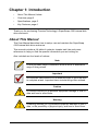
SUPERSWAP 4100
USER MANUAL
Version 1.3
SuperSwap 4100 User Manual
Copyright
© 2004 Promise Technology, Inc. All Rights Reserved.
Copyright by Promise Technology, Inc. (Promise Technology). No part of this
manual may be reproduced or transmitted in any form without the expressed,
written permission of Promise Technology.
Trademarks
Promise, and the Promise logo are registered in U.S. Patent and Trademark
Office. All other product names mentioned herein may be trademarks or
registered trademarks of their respective companies.
Important data protection information
You should back up all data before installing any drive controller or storage
peripheral. Promise Technology is not responsible for any loss of data resulting
from the use, disuse or misuse of this or any other Promise Technology product.
Notice
Although Promise Technology has attempted to ensure the accuracy of the
content of this manual, it is possible that this document may contain technical
inaccuracies, typographical, or other errors. Promise Technology assumes no
liability for any error in this publication, and for damages, whether direct, indirect,
incidental, consequential or otherwise, that may result from such error, including,
but not limited to loss of data or profits.
Promise Technology provides this publication “as is” without warranty of any kind,
either express or implied, including, but not limited to implied warranties of
merchantability or fitness for a particular purpose.
The published information in the manual is subject to change without notice.
Promise Technology reserves the right to make changes in the product design,
layout, and driver revisions without notification to its users.
This version of the User Manual supersedes all previous versions.
ii
Notices
Radio Frequency Interference Statement
This equipment has been tested and found to comply with the limits for a Class B
digital device, pursuant to Part 15 of the FCC Rules. These limits are designed to
provide reasonable protection against harmful interference in a residential
installation. This equipment generates, uses and can radiate radio frequency
energy, and, if not installed and used in accordance with the instruction may
cause harmful interference to radio communications. However, there is no
guarantee that interference will not occur in a particular installation. If this
equipment does cause harmful interference to radio or television reception, which
can be determined by turning the equipment off and on, the user is encouraged
to try to correct the interference by one or more of the following measures:
•
Reorient or relocate the receiving antenna.
•
Increase the separation between the equipment and receiver.
•
Connect the equipment into an outlet on a circuit different from that to which
the receiver is connected.
•
Consult Promise Technology, Inc. or an experienced radio/TV technician for
help.
This device complies with Part 15 of the FCC Rules. Operation is subject to the
following conditions: (1) This device may not cause harmful interference, and (2)
this device must accept any interference received, including interference that
may cause undesired operation. Note Only digital device equipment CERTIFIED
CLASS B should be attached to this equipment and that must have shielded
cables.
Power Supply Notice
Promise Technology recommends that you compare the capacity of your Power
Supply against the wattage required by your PC plus the disk drives you plan to
install in the SuperSwap 4100. Upgrade your Power Supply if necessary.
Do not use a Y-connector to share power between the SuperSwap 4100 and
another device.
Do not use a Y-connector to share power among the three power connectors on
the SuperSwap 4100.
Attach each SuperSwap 4100 power connector directly to the Power Supply.
iii
SuperSwap 4100 User Manual
iv
Contents
Chapter 1: Introduction . . . . . . . . . . . . . . . . . . . . . . . . . . . . . . . . . . . . . . . . . . . 1
About This Manual 1 . . . . . . . . . . . . . . . . . . . . . . . . . . . . . . . . . . . . . . . . . . . .
Overview . . . . . . . . . . . . . . . . . . . . . . . . . . . . . . . . . . . . . . . . . . . . . . . . . . . . 2
Specifications . . . . . . . . . . . . . . . . . . . . . . . . . . . . . . . . . . . . . . . . . . . . . . . . 3
Key Features . . . . . . . . . . . . . . . . . . . . . . . . . . . . . . . . . . . . . . . . . . . . . . . . . 4
Chapter 2: Installation . . . . . . . . . . . . . . . . . . . . . . . . . . . . . . . . . . . . . . . . . . . . 5
Unpack your SuperSwap 4100 . . . . . . . . . . . . . . . . . . . . . . . . . . . . . . . . . . . 5
Install the Enclosure . . . . . . . . . . . . . . . . . . . . . . . . . . . . . . . . . . . . . . . . . . . 5
Sequential Startup Option . . . . . . . . . . . . . . . . . . . . . . . . . . . . . . . . . . 10
Hot Swap Drive . . . . . . . . . . . . . . . . . . . . . . . . . . . . . . . . . . . . . . . . . . 11
Install a Disk Drive . . . . . . . . . . . . . . . . . . . . . . . . . . . . . . . . . . . . . . . . . . . 12
Remove a Disk Drive 13
Promise Array Management (PAM) . . . . . . . . . . . . . . . . . . . . . . . . . . . . . . 14
Chapter 3: Troubleshooting . . . . . . . . . . . . . . . . . . . . . . . . . . . . . . . . . . . . . . 15
LEDs . . . . . . . . . . . . . . . . . . . . . . . . . . . . . . . . . . . . . . . . . . . . . . . . . . . . . 15
Interpret LED Displays . . . . . . . . . . . . . . . . . . . . . . . . . . . . . . . . . . . . . . . . 16
Disk Drive Replacement . . . . . . . . . . . . . . . . . . . . . . . . . . . . . . . . . . . . . . . 19
Fan Replacement . . . . . . . . . . . . . . . . . . . . . . . . . . . . . . . . . . . . . . . . . . . . 20
Contact Technical Support . . . . . . . . . . . . . . . . . . . . . . . . . . . . . . . . . . . . . 21
Appendix . . . . . . . . . . . . . . . . . . . . . . . . . . . . . . . . . . . . . . . . . . . . . . . . . . . . . . 23
Limited Warranty . . . . . . . . . . . . . . . . . . . . . . . . . . . . . . . . . . . . . . . . . . . . . 23
Returning Product For Repair . . . . . . . . . . . . . . . . . . . . . . . . . . . . . . . . . . . 25
v
SuperSwap 4100 User Manual
vi
Chapter 1: Introduction
•
About This Manual, below
•
Overview, page 2
•
Specifications, page 3
•
Key Features, page 4
Thank you for purchasing Promise Technology’s SuperSwap 4100 internal disk
drive enclosure.
About This Manual
This User Manual describes how to setup, use and maintain the SuperSwap
4100 internal disk drive enclosure.
This manual includes a full table of contents, chapter task lists and crossreferences to help you find the specific information you are looking for.
Also included are four levels of notices:
Note
A Note provides helpful information such as hints or alternative
ways of doing a task.
Important
An Important calls attention to an essential step or point required
to complete a task. Important items include things often missed.
Caution
A Caution informs you of possible equipment damage or loss of
data and how to avoid them.
Warning
A Warning notifies you of probable equipment damage or loss of
data, or the possibility of physical injury, and how to avoid them.
1
SuperSwap 4100 User Manual
Overview
The SuperSwap 4100 drive enclosure installs easily into three contiguous 5.25inch component bays in your personal computer or workstation. The SuperSwap
4100 drive carrier and enclosure extend the data storage capabilities of your
system by adding up to four additional 3.5-inch form factor Serial ATA disk drives.
It also allows you to easily swap your disk drives in and out of your computer,
without the hassle of opening and closing your computer cabinet.
Drive
Carriers
Status
LEDs
Figure 1. SuperSwap 4100 Front View.
SuperSwap 4100 accepts only Serial ATA drives. It does not support (Parallel)
ATA or SCSI disk drives. When used with Promise Technology Serial ATA RAID
0, 1, 5 or 10 products, such as the FastTrak S150 SX4, SuperSwap 4100 allows
2
Chapter 1: Introduction
you to hot-swap a failed drive without powering down the system while fully
protecting disk drive and internal system components.
Power
Connector
(1of 3)
Fan (1of 2)
SATA
Connector
(1 of 4)
Management
Connector
Sequential
Startup
Switch
Daisy-Chain
Connector
(1 of 2)
Figure 2. SuperSwap 4100 Rear View.
Specifications
•
Fits most 3.5-inch form factor Serial ATA hard disk drives
•
Occupies three contiguous 5.25-inch component bays in PC chassis
•
Standard Serial ATA interface
•
Built-in Enclosure, Array Status and Drive Activity LED indicators
•
Two dedicated cooling fans
•
Durable metal construction
•
Fully-ventilated drive carriers
•
Unique handle design automatically disengages drive
•
Housing Assembly dimensions (HWD): 4.96 x 5.75 x 8.07 inches (126 x 146
x 205 mm)
•
Drive Carrier dimensions (HWD): 1.07 x 4.21 x 6.81 inches (27.2 x 107 x 173
mm)
•
Operating temperatures: 32° to 110°F (0°C to 45°C)
•
Operating himidity: 5% to 95% non-condensing
3
SuperSwap 4100 User Manual
Key Features
•
Supports standard 7,200 rpm and 10,000 rpm Serial ATA drives
•
Combine with Promise Serial ATA RAID products to provide striping (RAID
0), mirroring (RAID 1), distributed parity (RAID 5) and mirroring/striping
(RAID 10) at the hardware level
•
Supports Promise RAID and non-RAID Serial ATA products
•
Supports hot-swapping of disk drives
•
Global LED displays high-level condition of the SuperSwap enclosure
•
Status LEDs indicate high-level condition of the disk drives
•
Activity LEDs display during normal disk drive activity
•
Allows auto-sensing of Serial ATA drive and implementation of 150MB/sec
burst transfers
•
Supports Promise Array Management (PAM) software when using a Promise
RAID controller, such as FastTrak S150 SX4
4
Chapter 2: Installation
•
Unpack your SuperSwap 4100 (below)
•
Install the Enclosure (below)
•
Install a disk drive (page 12)
•
Remove a disk drive (page 13)
Unpack your SuperSwap 4100
The SuperSwap 4100 box contains the following items:
•
SuperSwap Drive Enclosure •
3-pin to 4-pin SMBus Cable
•
(4) Drive Carriers
•
6-pin to 6-pin Daisy Chain Cable
•
User Manual
•
(16) Screws to attach disk drives to
drive carriers
•
3-pin to 3-pin SMBus Cable •
(SATA II compliant)
(8) Screws to mount Enclosure into PC
chassis
Warning
SuperSwap 4100, like other parts of your system, is subject to
damage by static electricity. Be sure that youíre properly grounded
(Promise recommends that you wear an anti-static strap or touch
a grounded object) and that you unplug your system before
installing SuperSwap 4100 or handling its components.
There are two phases to install the SuperSwap 4100 into your computer:
•
Install the enclosure in your computer chassis
•
Install a disk drive in the drive carrier
Install the Enclosure
To install the enclosure in your computer chassis, follow these steps:
1.
Power down your computer and unplug the power cord.
2.
Remove the computer cover.
3.
Arrange the drive assemblies to arrange for three contiguous, free 5.25-inch
drive bays. Remove any bezels covering them.
5
SuperSwap 4100 User Manual
4.
Remove the drive carriers from the SuperSwap 4100 enclosure and set
them aside.
5.
If your PC chassis uses slide brackets (above), attach two slides to each
side of the SuperSwap enclosure. Otherwise, continue with Step 6.
6
Chapter 2: Installation
6.
Carefully slide the SuperSwap 4100 enclosure into the drive bays.
7.
Align the front of the housing assembly with the front of your computer.
8.
If your PC chassis has fixed mounting brackets, install and snug the eight
screws into the eight threaded mounting holes (four on each side) of the
housing assembly. Otherwise, continue with Step 9.
Note
If you are installing two SuperSwap 4100s into the same computer
chassis, install the other SuperSwap now before making any cable
connections.
7
SuperSwap 4100 User Manual
Port 1
SuperSwap
4100
Port 2
Port 3
Port 4
Serial ATA
Cable
FastTrak
Port 1
9.
Port 2
Port 3
Port 4
SX4
150
J 1
FastTrak S150 SX4
Controller Card
Connect a Serial ATA cables from your FastTrak or SATA 150 Controller
card.
Promise recommends connecting the Serial ATA cables in Port number
order. For example, the top connector is Port 1 and it connects to Port 1 on
the FastTrak controller card, as shown above.
8
Chapter 2: Installation
Daisy Chain
IN Connector
Management
Connector
SuperSwap
4100
Daisy Chain
OUT Connector
SMBus 3-pin to
4-pin Cable or
SMBus 3-pin to
3-pin Cable
Daisy Chain
6-pin Cable
To Daisy Chain IN
Connector of next
SuperSwap 4100
Management
Connector
FastTrak
SX4
150
J 1
FastTrak S150 SX4
Controller Card
Step 10 applies to the FastTrak RAID Controller only. If you have a SATA
150 Controller, go to Step 11.
10. Connect the 3-to-4 pin or 3-to-3 pin SMBus cable from the Management
connector on the FastTrak Controller card to the Management connector on
the back of the housing assembly.
If you are installing multiple SuperSwap 4100s, connect the SMBus cable to
the first SuperSwap as described in Step 10. Then install a 6-pin daisy-chain
9
SuperSwap 4100 User Manual
cable from the daisy-chain OUT connector of the first SuperSwap to the
daisy-chain IN connector of the second.
Power
Connectors
Sequential
Startup Switch
11. Connect three of your computer’s internal power cables to the power
connectors on the back of the SuperSwap enclosure.
Provide a direct connection to the power supply for all three SuperSwap
power connectors..
Cautions
•
Promise Technology recommends that you compare the
capacity of your Power Supply against the wattage required
by your PC plus the disk drives you plan to install in the
SuperSwap 4100. Upgrade your Power Supply if necessary.
•
Do not use a Y-connector to share power between the
SuperSwap 4100 and another device or to share power
among the three power connectors on the SuperSwap 4100.
Sequential Startup Option
Sequential Startup enables SuperSwap to start one disk drive at a time in
order to eliminate a sudden heavy draw on the computer’s power supply.
10
Chapter 2: Installation
The switch is located on the back of the SuperSwap enclosure (see above).
ON is to the left, OFF is to the right.
The ON setting spins up the first two disk drives at the same time, then a
two-second pause before spinning up the third disk drive, then another twosecond pause before spinning up the fourth disk drive.
The OFF setting causes SuperSwap to spin up its disk drives when the
power comes on.
12. Replace the computer’s cover and reinstall the power cord.
Hot Swap Drive
The Promise SuperSwap 4100 is designed to work with the Promise FastTrak
Serial ATA RAID controllers that support RAID 0, RAID 1, RAID 5 and RAID 10,
such as the FastTrak S150 SX4. When used with the supported SATA RAID
controllers, SuperSwap 4100 enables hot swapping of disk drives.
Hot swapping means you can remove a drive while your system is operating and
replace it with another. You perform a hot swap when one of the drives has failed
and needs replacement. The PAM Software reports drive problems and identifies
which drive, by Channel (Port) number, needs replacement.
Caution
In all other cases, before you remove or install a disk drive, power
down your system and ground yourself. Failure to do so may
result in damaging the drive, the controller card or other
components and could result in data loss.
11
SuperSwap 4100 User Manual
Install a Disk Drive
1.
Carefully place a Serial ATA disk drive into the drive carrier and slide it all the
way to the back.
12
Chapter 2: Installation
2.
Install and tighten the four mounting screws to secure the disk drive in the
drive carrier.
3.
Carefully slide the drive carrier into the housing assembly with the handle
turned out all the way.
4.
As the carrier snaps into place, the handle will swing inward.
5.
Press the handle flat against the drive carrier to fully seat it.
Note
The previous generation of SuperSwap enclosures used the key
lock to activate power as well as secure the drive carrier.
SuperSwap 4100 uses only the handle to secure the drive carrier.
Power is available at all times, in order to comply with SATA 150
requirements.
Remove a Disk Drive
1.
Pull the drive carrier handle out and swing it to the left.
2.
Pull the drive carrier out of the SuperSwap enclosure.
3.
Remove the four screws attaching the disk drive to the drive carrier.
4.
Lift the disk drive from the drive carrier.
5.
Reinstall the disk drive as described under Install a Disk Drive, above.
13
SuperSwap 4100 User Manual
Promise Array Management (PAM)
You can combine SuperSwap 4100 with the Promise FastTrak S150 SX4 RAID
Controller and PAM Software on your PC. PAM provides a graphic user interface
(GUI) for array management and enclosure monitoring.
The screen above appears when you click the SuperSwap
icon in PAM. It
reports fan speeds, enclosure temperature, power status and the status of the
disk drives in the SuperSwap enclosure.
While the LEDs on the front of the SuperSwap 4100 indicate general conditions,
PAM reports specific values. The Disk window shows the carrier position in
SuperSwap enclosure and the controller port to which each disk drive is
connected. This feature helps you identify a disk drive that may need attention.
There are many other functions that PAM does. We have only mentioned how
SuperSwap 4100 appears in PAM.
The PAM Software ships with the Promise Serial ATA RAID Controller. You can
also download PAM from the Promise website at www.promise.com.
14
Chapter 3: Troubleshooting
•
LEDs (below)
•
Interpret LED Displays (page 16)
•
Disk Drive Replacement (page 19)
•
Fan Replacement (page 20)
•
Contact Technical Support (page 21)
LEDs
Enclosure
Disk Drive 1
Disk Drive 2
Disk Drive 3
Disk Drive 4
Figure 1. SuperSwap 4100 has one LED for Enclosure Status and two
LEDs for each disk drive.
Notes
•
The LEDs function only with the FastTrak RAID Controller.
They do not function with the SATA 150 Controller.
•
As long as the PAM Software or Promise BIOS indicate that
your array status is Functional, your array is operating
normally.
15
SsuperSwap 4100 User Manual
Troubleshooting is based on observing and analyzing LED colors. There are
three types of LEDs on SuperSwap 4100:
•
Enclosure
– Reports enclosure conditions including voltage,
termperature and fan speed
•
Status
– Reports specific disk drive conditions
•
Activity
– Reports read and write activity on each disk drive
The chart below lists the meanings of the various LED states:
Interpret LED Displays
LEDs
State
Status
Enclosure
Activity
Green
Disk drive is present
and ready
Disk drive is present
and ready
Normal status
Blinking
n/a
Read/write activity
n/a
Amber
Disk drive:
n/a
• is spinning up
• is critical
• is rebuilding
• reports a SMART
error
1 incident
(see below)
Red
Disk drive:
• is offline
• is not installed
n/a
2 or more incidents
(see below)
Dark
Power is off
Disk drive:
• has failed
• is not installed
Disk drives are
spinning up
Enclosure is critical
but still functional
Attention required
An incident refers to one occurance of out-of-range voltage, temperature or fan
speed. Any incident requires immediate attention.
Event: A Status
LED is steady green.
Cause: This is the normal condition when the computer has fully booted and the
disk drive is ready.
16
Chapter 3: Troubleshooting
Event: A Status
LED is amber (yellow).
Cause: The disk drive is spinning up as the computer is booting. Wait for the
computer to finish. If the computer is fully booted, the drive could be Critical and
in the process of rebuilding. The LED will return to green status when the rebuild
is complete and successful.
Fix: If one Status LED continues to display amber, remove the disk drive for
testing. Return the drive to service or replace it based on test results.
Event: A Status
LED is red.
Cause: The drive has failed. A failed drive may be marked as such because of
power failure, hot removal or media access problems (such as a bad sector
which fails retry). A Status LED is also red when there is no drive in the carrier.
Fix: Replace the failed drive. The new drive will be assigned to the failed drive’s
original location and a rebuild operation will begin automatically. The LED turns
amber during the rebuild, then green when the rebuild is complete and
successful.
Event: The LEDs do not light.
Cause: There is no power to the SuperSwap enclosure.
Fix: If the rest of your computer system is working, shut down the computer,
open the case, check and correct the power connection to the SuperSwap
enclosure.
Event: An Activity
LED is steady green.
Cause: This is the normal condition when the computer has fully booted and the
disk drive is present and ready.
Event: An Activity
LED is blinking green.
Cause: This is the normal condition when there is disk activity (read or write)
executing on the drive.
Event: An Activity
LED is dark.
Cause: No disk drive detected or the disk drive has failed.
Fix: If a disk drive is present, reinstall it. If it still doesn’t work, replace the disk
drive.
Event: The Enclosure
LED is steady green.
Cause: This is the normal condition within the enclosure.
17
SsuperSwap 4100 User Manual
Event: The Enclosure
LED is amber (yellow).
Cause: There is one incident of voltage, temperature or fan speed is out of
specification. The SuperSwap will still function.
Fix: Run the PAM software (on the FastTrak CD) and click on Enclosure View for
specific information.
If you do not have PAM, check the following items:
•
All drive carriers are properly installed in the enclosure, even if they have no
disk drive.
•
There are three separate direct connections from the power supply to the
SuperSwap and no Y-cables are used.
•
Compare the capacity of your Power Supply against the wattage required by
your PC plus the disk drives installed in the SuperSwap 4100. Upgrade your
Power Supply if necessary.
•
Both fans are turning (run the PC with the cover off).
•
Air space around the fans. Relocate cables and wires as needed.
•
Check the temperature of each disk drive (with the PC powered down).
Event: The Enclosure
LED is red.
Cause: There are multiple incidents of voltage, temperature or fan speed out of
specification. The SuperSwap is failing.
Fix: Run the PAM software (on the FastTrak CD) and click on Enclosure View for
specific information.
Event: PAM reports voltage out of specification.
Cause: The 12V or 5V supplies to SuperSwap are incorrect.
Fix: Power down the PC, open the case and check the power connections to
SuperSwap. There should be three separate direct connections from the power
supply to the SuperSwap. Do not use any Y-cables on the power connectors.
Compare the capacity of your Power Supply against the wattage required by your
PC plus the disk drives installed in the SuperSwap 4100. Upgrade your Power
Supply if necessary.
Event: PAM reports fan speed out of specification.
Cause: One of the fans is turning too slowly, PAM reports them by number.
Fix: Power down the PC and open the case. Disconnect and remove the
SuperSwap enclosure. Remove and replace the faulty fan. The top fan is Fan 1.
The bottom fan is Fan 2.
18
Chapter 3: Troubleshooting
Event: PAM reports temperature out of specification.
Cause: The enclosure temperature has risen above 52°C (126°F).
Fix: Verify that all the drive carriers are properly installed in the enclosure. Check
fan operation using PAM. If these are OK, power down the PC and open the
case. Check for air space around the fans and relocate cables and wires as
needed.
A disk drive that runs too hot could cause high enclosure temperature. Power
down the PC, open each drive carrier and carefully touch the disk drive with your
finger. Normally drives are warm. If a drive is hot, replace it.
Disk Drive Replacement
If you are replacing a hot-swap disk drive, you can do this proceedure with the
PC running. To replace a disk drive under any other conditions, power down the
PC before you begin.
1.
Swing the drive carrier handle out and to the left.
2.
Pull the drive carrier out of the SuperSwap enclosure.
3.
Remove the four screws attaching the disk drive to the drive carrier.
4.
Lift the disk drive from the drive carrier.
5.
Carefully place a disk drive into the drive carrier and slide it all the way to the
back.
6.
Install and tighten the four mounting screws to secure the disk drive in the
drive carrier.
7.
Carefully slide the drive carrier into the housing assembly with the handle
turned out all the way.
8.
As the carrier snaps into place, the handle will swing inward.
9.
Press the handle flat against the drive carrier to fully seat it
19
SsuperSwap 4100 User Manual
Fan Replacement
Mounting Pin
Mounting Screw
Wire Bracket
Power Connector
Fan
To replace a fan on the SuperSwap 4100, do the following:
1.
Power down the PC.
2.
Remove the SuperSwap enclosure from the PC chassis.
3.
Remove the two mounting screws on the fan.
4.
Pull the fan from the two mounting pins and the wire away from the bracket.
Do not bend the bracket.
5.
Unplug the power connector.
6.
Plug the power connector of the new fan.
7.
Lay the wire through the bracket and place the fan onto the two mounting
pins.
8.
Install the two mounting screws.
9.
Reinstall the SuperSwap enclosure into the PC chassis.
10. Power up the PC and check fan function.
20
Chapter 3: Troubleshooting
Contact Technical Support
Promise Technical Support provides several support options for Promise users to
access information and updates. We encourage you to use one of our electronic
services, which provide product information updates for the most efficient service
and support.
If you decide to contact us, please have the following information available:
•
Product model and serial number
•
BIOS and driver version numbers
•
A description of the problem / situation
•
System configuration information, including: motherboard and CPU type,
hard drive model(s), ATA/ATAPI drives & devices, and other controllers.
Technical Support Services
Promise Online™ Web Site
http://www.promise.com
(technical documents, drivers, utilities, etc.)
USA Tech Support Center
E-mail Support
[email protected]
Fax Technical Support
(408) 228-6401
Attention: Technical Support
Phone Technical Support
(408) 228-6402
7:30-5:30pm M-F Pacific Standard Time
If you wish to write us for
support:
Promise Technology, Inc.
Attn: Technical Support
1745 McCandless Drive
Milpitas, CA 95035, USA
21
SsuperSwap 4100 User Manual
European Tech Support
E-mail Support
[email protected]
Fax Technical Support
+31 (0) 40 256 9463
Attention: Technical Support
Phone Technical Support
+31 (0) 40 235 2600
8:30-5:00pm The Netherlands Time
If you wish to write us for
support:
Promise Technology Europe B.V.
Attn: Technical Support
Luchthavenweg 81-125
5657 EA Eindhoven, The Netherlands
Pacific Rim Sales Office
E-mail Support
[email protected]
Fax Technical Support
+886 3 564 53 13
Attention: Technical Support
Phone Technical Support
+886 3 578 23 95 (ext. 8873)
9:00-5:30pm Taiwan Time
If you wish to write us for
support:
Promise Technology, Inc.
Attn: Technical Support
2F, No. 30, Industry E. Rd. IX
Science-based Industrial Park
Hsinchu, Taiwan, R.O.C.
China Office
E-mail Support
[email protected]
Fax Technical Support
+86 10 6872 3940
Attention: Technical Support
Phone Technical Support
+86 10 6872 3941
9:00-6:00pm China Time
If you wish to write us for
support:
Promise Technology China
Attn: Technical Support
Room 3213, No. 11
South Zhong Guan Cun Street
Hai Dian District, Beijing 100081
P.R. China
22
Appendix
•
Limited Warranty (page 23)
•
Returning product for repair (page 25)
Limited Warranty
Promise Technology, Inc. (“Promise”) warrants that for three (3) years from the
time of the delivery of the product to the original end user:
a)
the product will conform to Promise’s specifications;
b)
the product will be free from defects in material and workmanship under
normal use and service.
This warranty:
a)
applies only to products which are new and in cartons on the date of
purchase;
b)
is not transferable;
c)
is valid only when accompanied by a copy of the original purchase
invoice.
d)
Is not valid on spare parts, fans, and power supplies
This warranty shall not apply to defects resulting from:
a)
improper or inadequate maintenance, or unauthorized modification(s),
performed by the end user;
b)
operation outside the environmental specifications for the product;
c)
accident, misuse, negligence, misapplication, abuse, natural or
personal disaster, or maintenance by anyone other than a Promise or a
Promise-authorized service center.
Disclaimer of other warranties
This warranty covers only parts and labor, and excludes coverage on software
items as expressly set above.
Except as expressly set forth above, Promise DISCLAIMS any warranties,
expressed or implied, by statute or otherwise, regarding the product, including,
without limitation, any warranties for fitness for any purpose, quality,
merchantability, non-infringement, or otherwise. Promise makes no warranty or
representation concerning the suitability of any product for use with any other
item. You assume full responsibility for selecting products and for ensuring that
23
SuperSwap 4100 User Manual
the products selected are compatible and appropriate for use with other goods
with which they will be used.
Promise DOES NOT WARRANT that any product is free from errors or that it will
interface without problems with your computer system. It is your responsibility to
back up or otherwise save important data before installing any product and
continue to back up your important data regularly.
No other document, statement or representation may be relied on to vary the
terms of this limited warranty.
Promise’s sole responsibility with respect to any product is to do one of the
following:
a)
replace the product with a conforming unit of the same or superior
product;
b)
repair the product.
Promise shall not be liable for the cost of procuring substitute goods, services,
lost profits, unrealized savings, equipment damage, costs of recovering,
reprogramming, or reproducing of programs or data stored in or used with the
products, or for any other general, special, consequential, indirect, incidental, or
punitive damages, whether in contract, tort, or otherwise, notwithstanding the
failure of the essential purpose of the foregoing remedy and regardless of
whether Promise has been advised of the possibility of such damages. Promise
is not an insurer. If you desire insurance against such damage, you must obtain
insurance from another party.
Some states do not allow the exclusion or limitation of incidental or consequential
damages for consumer products, so the above limitation may not apply to you.
This warranty gives specific legal rights, and you may also have other rights that
vary from state to state. This limited warranty is governed by the State of
California.
Your Responsibilities
You are responsible for determining whether the product is appropriate for your
use and will interface with your equipment without malfunction or damage. You
are also responsible for backing up your data before installing any product and
for regularly backing up your data after installing the product. Promise is not liable
for any damage to equipment or data loss resulting from the use of any product.
24
Appendix
Returning Product For Repair
If you suspect a product is not working properly, or if you have any questions
about your product, contact our Technical Support Staff through one of our
Technical Services, making sure to provide the following information:
•
Product model and serial number (required)
•
Return shipping address
•
Daytime phone number
•
Description of the problem
•
Copy of the original purchase invoice
The technician will assist you in determining whether the product requires repair.
If the product needs repair, the Technical Support Department will issue an RMA
(Return Merchandise Authorization) number.
Return ONLY the specific product covered by the warranty (do not ship cables,
manuals, diskettes, etc.), with a copy of your proof of purchase to:
USA and Canada:
Promise Technology, Inc.
Customer Service Dept.
Attn.: RMA # ______
1745 McCandless Drive
Milpitas, CA 95035
Other Countries:
Return the product to your dealer
or retailer.
Contact them for instructions
before shipping the product.
You must follow the packaging guidelines for returning products:
•
Use the original shipping carton and packaging
•
Include a summary of the product’s problem(s)
•
Write an attention line on the box with the RMA number
•
Include a copy of proof of purchase
You are responsible for the cost of insurance and shipment of the product to
Promise. Note that damage incurred due to improper transport or packaging is
not covered under the Limited Warranty.
When repairing returned product(s), Promise may replace defective parts with
new or reconditioned parts, or replace the entire unit with a new or reconditioned
unit. In the event of a replacement, the replacement unit will be under warranty
for the remainder of the original warranty term from purchase date, or 30 days,
whichever is longer.
25
SuperSwap 4100 User Manual
Promise will pay for standard return shipping charges only. You will be required to
pay for any additional shipping options (such as express shipping).
26