1
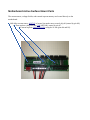
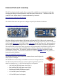
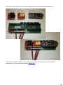
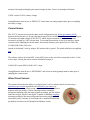
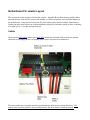
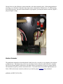
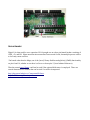
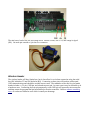
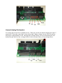
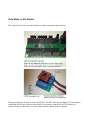
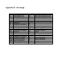
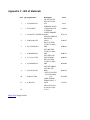
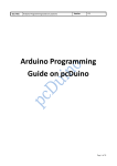
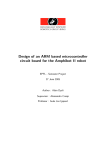
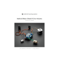
AEV 6 Integrating an Off-the-Shelf Microcontroller & Motor Control For the Advanced Energy Vehicle Project User Manual, Rev.0 Table of Contents AEV Controller Design Goals - Results....................................................................................................3 Motherboard Active Surface Mount Parts.................................................................................................4 External Parts and Assembly......................................................................................................................5 Pinouts........................................................................................................................................................7 Motors...................................................................................................................................................7 Voltage Sensing.....................................................................................................................................7 Current Sensor.......................................................................................................................................8 Wheel Count Sensors............................................................................................................................8 Motherboard Pin Header Layout................................................................................................................9 Cables....................................................................................................................................................9 Sensor Pin Headers..............................................................................................................................10 Button Extender ..................................................................................................................................11 Servo Header.......................................................................................................................................12 Wireless Header...................................................................................................................................13 Unused Analog Pin Headers................................................................................................................14 Third Motor or SPI Header.................................................................................................................15 I2C Bus Extension Header..................................................................................................................16 Appendix A – The Unofficial Arduino Nano Pinout ...............................................................................17 Appendix B – Pin Usage..........................................................................................................................18 Appendix C - Bill of Materials................................................................................................................19 AEV Controller Design Goals - Results Light Weight 23 grams (bare motherboard) 43 grams (w/ cables, Arduino, motor controllers) Small Size 1.2 inches wide x 3.7 inches long x 0.625 inches high Mounting hole spacing is 1 by 3.5 inches Simple Microcontroller with Easy to Use Software Arduino Nano microcrontroller http://www.gravitech.us/arna30wiatp.html Uses the open source Arduino Integrated Development Editor (IDE) Software available from http://arduino.cc/ High Motor Output Currents Ability to supply 2 amps (3 amp peak) per motor Uses parallel operation of the TB6612FNG motor driver https://www.sparkfun.com/products/9457 Current and Voltage Sensing Allow constant current and voltage sensing throughout a run Hall effect current sensor ACS715LLCTR20AT Simple 10K/10K/10K voltage divider allows for monitoring of batteries up to 15 volts Extra memory to record voltage and current for a two minute run at 50 ms intervals Additional 32k bytes of eeprom memory (24LC256, uses i2c bus) Low Cost ~$75 (not including development cost) Motherboard Active Surface Mount Parts The current sensor, voltage divider, and external eeprom memory are located directly on the motherboard. ● Hall effect current sensor, ACS715, is located just under motor control chip #2 (sensed by pin A6). ● Three resistor voltage divider (10K/10K/10K), sensed by pin A7. ● External eeprom, 24LC256T-I/SN, using the i2c bus (pins A4 and A5). External Parts and Assembly The AEV motherboard pulls together three commercially available electronic daughter boards thus leveraging the design work and production level discounts of these devices. The heart of the AEV controller is the Arduino Nano 3.0 board manufactured by Gravitech: http://store.gravitech.us/arna30wiatp.html The Arduino Nano uses and open source design accepted by the Arduino foundation. http://arduino.cc/en/Main/ArduinoBoardNano The Nano differs from the Arduino UNO in that it still uses the FTDI USB to serial converter and breaks out an additional two analog pins from the Atmel 328 microprocessor chip. It is a 5 volt device with 12 usable digital pins (2-13), and 8, 10bit, analog pins (A0-A7), the first six of which can also be used as digital pins by addressing them as 14-19. The pin out of the Nano is provided in Appendix A. The Arduino Nano controls the current provided to the recommended E-Flite EFLH1322 direct drive motors by using the built-in Pulse Width Modulation (PWM) of the Nano that is decoded by the Toshiba motor control chip. The chip also provides an integrated H bridge providing for current reversal (motor reverse). These surface mounted motor control chips, TB6612FNG, are placed on a breakout board by Sparkfun: https://www.sparkfun.com/products/9457 The motherboard design allows the surface mounted moor control chips to be easily replace if damaged. The Toshiba motor control chips can handle two motors at 1.2 amps each, but the AEV mother board ties these two circuits together in parallel to give 2.4 amps for a single motor, i.e. the following inputs are tied together: • Ain1 and Ain2 (H bridge input control logic) • Bin1 and Bin2 (H bridge input control logic) • PWMA and PWMB (PWM input signal) • A01 and B01 (motor lead output) • A02 and B02 (motor lead output) The Arduino Nano and the two motor control chips mount to the mother board as shown below: Motor control 2 Motor control 1 Arduino Nano Heat sinks were added to the motor control chips to help control over temperatures during extended high speed runs. The heat sinks are modified Digikey parts. Pinouts Motors The Arduino Nano has 12 usable digital pins (D2-D13), and 8 usable analog pins (A0-A7). Analog pins A0 to A5 can be used as either an analog inputs (called as A0-A5) or as a digital pins (called as 14-19). Each motor requires a specialized digital pin capable of sending a PWM signal for speed control, and two digital outputs to control the H-bridge for reversing and braking. The Toshiba TB6612FNG h-bridge logic is shown in the following table taken from the device data sheet: To conserve pins, the STBY pin is wired HIGH (+5 volts), so the “Standby” state is not available. The pins used are: Motor 1 2 3 IN1 IN2 7 16 10 8 17 12 PWM 5 6 11 Motor 3 is an optional device; pins 10, 11, and 12 are merely brought out to a pin header. The location of these pin outs are shown in the Pin Header Breakout section. Voltage Sensing Analog pin 6 (A6) is used to sense the voltage on the last junction prior to ground of a 10K/10K/10K series resistor voltage divider connected from battery '+' to battery '-' also tied to Arduino ground. A voltage divider is used because the recommended battery, an E-Flite EFLB8002SJ30, two cell Lipo has a charge voltage of about 8.4 volts. The Arduino Nano analog pins can sense voltages up to a maximum of 5 volts. By using the three resistor voltage divider, a LiPo 2 cell or 3 cell battery can be monitored by simply multiplying the sensed voltage by three. Here is an example calculation: 3*ADC counts*5/1024 = battery voltage AnalogReference must be set to “DEFAULT,” and at least one analog sample taken, prior to sampling the battery voltage. Current Sensor The ACS715 current sensor uses the same circuit configuration as the Pololu part number #1186, however the Pololu part is a 30 amp chip and the part used for the AEV is a 20 amp model. Analog pin A7 monitors the output voltage of the ACS715 which outputs a nominal 0.5 volts at 0 amps and increases in voltage by 0.185 volts per amp. To increase the resolution of the 10 bit analog to digital converter while sampling the current sensor, the external reference pin is pulled down to 2.46 volts, (5*32K)/(32K+33K)=2.46 volts , instead of the default 5 volts by using a 33K resistor tied to ground. The actual calculation is explained here. The software collects the initial ADC count (ADCi) prior to the run which corresponds to the 0.5 volts at zero amps. During the run the current calculation in amps is: (2.46*(ADC counts-ADCi)/1024)/0.185 = amps AnalogReference must be set to “EXTERNAL” and at least on analog sample must be taken prior to sampling the current sensor. Wheel Count Sensors The system software has the ability to use digital pins 2 and 3 to monitor wheel rotation using a quadrature type encoder algorithim with reflectance type sensors, as shown in the immediate picture, using a wheel with alternating reflective and non-reflective surfaces. Wheel counting requires continuous background updating while the main program is running, and the Arduino Nano has two pins, digital 2 and digital 3, capable of handling interrupts, Interrupts provide the necessary background processing triggers. Pins 2 (interrupt 0) and 3 (interrupt 1) are brought out on separate motherboard pin headers and shown in the 'Motherboard Headers' section. Motherboard Pin Header Layout This section shows the location of the broken out pins. Appendix B is a table showing Arduino Nano pins and their use with the AEV project and whether or not they are broken out to separate headers on the motherboard. Some pins are not used at all, while others can be used for multiple items (buses). Usable pins have been broken out on the motherboard, usually in pin header groups of three, consisting of a signal pin, a +5 volt pin, and a ground pin. Cables There are three JST cables (battery uses male JST) attached to the board, with room for an optional cable that would supply power to a separate motor control chip used for a third motor. The motor cables are not polarity sensitive (just determines initial motor rotation direction). The battery cable is polarity sensitive and can easily destroy the entire board if wired backwards. Sensor Pin Headers As previously mentioned, digital pin 2, and digital pin 3 are interrupts used for background processing of the quadrature type wheel counter implemented in the AEV6 software. The provided sensors are attached to a three wire extension with wire colors of white, red, and black. For consistency, please make sure the black wire attaches to the labeled ground (GND) pin of the sensor. The sensors attach to the following locations (black wire to ground, white to digital pin). Shown below are the reflectance sensors attached to the wheel mounting strut. When using quadrature encoding, you will need to determine the proper sensor orientation by trail and error. If, when moving forward on the track, the track counts decrease or go negative, just swap the sensor locations ( digital 2 plug and digital 3 plug). Button Extender The pushbutton mounted on the motherboard is held down for a second or so as a signal to the software to begin the run. This button may not be in a convenient location when the vehicle model is complete. The two pin female header located next to the button allows an extension to be run to a remote button. The button has no pull-up resistor associated with it. To use the button, the parallel implementation of D4 to GND on the button extension, make sure you use the proper pinMode setup command: pinMode (4, INPUT_PULLUP) ; Servo Header Digital 9 is often used for servo operation D9 is brought out on a three pin female header consisting of GND, +5v, and D9. Please note that microcontrollers have several clocks, but multiple process calls to a clock may cause conflicts. “On boards other than the Mega, use of the [servo] library disables analogWrite() (PWM) functionality on pins 9 and 10, whether or not there is a Servo on those pins.” (from Arduino Reference) Thus the normal servo library could not be used if the optional third motor is employed. There are several alternate servo libraries that can be tried if a conflict is suspected: http://playground.arduino.cc/ComponentLib/Servo http://arduiniana.org/libraries/pwmservo/ The mini-servo has brown, red, and orange wires. Brown is GND, red is +5v, and orange is signal (D9). Use male pin extender to join the two connectors. Wireless Header The wireless header will have limited use, but it does allow for a wireless connection using the serial bus (D0, labeled as TX and D1 labeled as RX). Connecting to these pins will interfere with normal USB communications and should be avoided in most cases. The remainder of the this five pin female header includes a +5V pin, GND pin, and a hardware reset pin. In some cases it may be desirable to do a hardware reset. Connecting the reset pin temporarily to the GND pin will restart the microcontroller and then restart the program that has been flashed to the microcontroller. Unlike a software watchdog reset, all caches are flushed as well which is usually an advantage. Unused Analog Pin Headers Two analog pins A0 and A1 are available for use. These pins can also be called as digital pin 14 and 15 respectively. Never place more than 5 volts on these pins. Battery voltage of a two cell LiPo used for this project is approximately 8 volts. Placing battery voltage directly on one of the Arduino pins will destroy that pin, which is why a voltage divider is used to measure battery voltage during the run. Third Motor or SPI Header The control section of the optional third motor can be connected as shown below: This same header can be used to access the SPI bus. The AEV software uses digital 13 as an indicator, conflicting with SPI use, but this could easily be overcome by using the D14 or D15 headers as indicators using an LED with a 330 ohm resistor current limiting resistor to ground. I2C Bus Extension Header The Arduino communicates with the external eeprom using the i2c bus (address 80). The i2c bus is addressable and can handle multiple items such as i2c displays, other addressable sensors, and sensor interfaces. Maximum wiring distance is about three feet. Appendix A – The Unofficial Arduino Nano Pinout From: http://www.pighixxx.com/downloads/arduino-nano/ Appendix B – Pin Usage AEV 6 D0 D1 D2 D3 D4 D5 D6 D7 D8 D9 D10 D11 D12 D13 A0/14 A1/15 A2/16 A3/17 A4/18 A5/19 A6/20 A7/21 REF Pin Usage Serial Input/Reserved Serial Input/Reserved Interrupt 0 Interrupt 1 Button PWM Motor 1 PWM Motor 2 H-bridge logic 1 for Motor 1 H-bridge logic 2 for Motor 1 Available H-bridge logic 1 for Motor 3 PWM Motor 3 H-bridge logic 2 for Motor 3 Built-in LED Available Available H-bridge logic 1 for Motor 2 H-bridge logic 2 for Motor 2 I2C-SDA for ext eeprom I2C-SCL for ext eeprom battery voltage sensor current sensor tied to 33K resistor to +5 To Header? Yes Yes Yes Yes Yes No No No No Yes Yes Yes Yes Yes Yes Yes No No Yes Yes No No No Comment Serial Input or Wireless Use Only Serial Input or Wireless Use Only Used for wheel count sensor Used for wheel count sensor Allows for remote Possible servo usage Available – SPI/CS Available – SPI/MOSI Available – SPI/MISO SPI/SCK eeprom uses addr 80 eeprom uses addr 80 EXTERNAL gives 2.46 volts Appendix C - Bill of Materials Item Qty Digikey Stk # 1 1 2 1 3 1 4 1 5 2 6 3 7 2 8 1 9 1 10 1 11 4 12 Eagle Files (single board) Description SW SLIDE DPDT SIDE ACT GOLD SS22SDH4ND 28V TERMINAL BLOCK ED1520ND 3.5MM 8POS PCB IC EEPROM 256KBIT 400KHZ 24LC256TI/SNDKRND 8SOIC SENSOR CURRENT 20A 5V UNI 62012306ND 8SOIC RES 4.7K OHM 1/10W 5% 0603 SMD P4.7KGDKRND RES 10K OHM 1/10W 5% 0603 P10KGDKRND SMD CAP CER 0.1UF 31113436ND 50V Y5V 0603 RES 33K OHM 1/10W 5% 0603 P33KGDKRND SMD CAP CER 1000PF 50V 10% X7R 0603 44556596ND SWITCH TACTILE SPSTNO 0.02A P8081SCTND 15V CONN HEADER FEMALE 8POS .1" GOLD S7041ND Other Pin Header As Shown, Equiv. To #11 Price 2.232 1.38076 0.72379 2.08287 0.00891 0.00721 0.00955 0.01605 0.02232 0.16402 0.4122