1
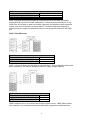
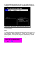
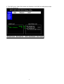
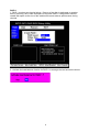
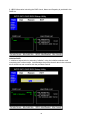
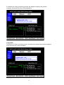
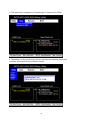
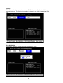
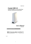
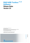
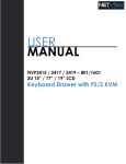
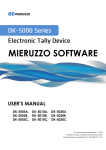
ESATA PCI CARD
User’s Manual
Introduction ................................................................................................................. 3
System Requirements ............................................................................................. 3
RAID Introduction.................................................................................................... 3
BIOS Configuration Utility ........................................................................................... 5
Configuring Arrays .................................................................................................. 5
RAID Mode Definitions............................................................................................ 5
BIOS Configuration Utility ....................................................................................... 5
Create a RAID Array ......................................................................................................... 6
Initialize RAID ................................................................................................................. 10
Verify RAID ..................................................................................................................... 11
Delete RAID .................................................................................................................... 12
Rebuild ............................................................................................................................ 13
Change to Pass-through ................................................................................................. 15
Reserve for RAID............................................................................................................ 15
Rescan ............................................................................................................................ 16
Exit BIOS Utility............................................................................................................... 16
Application and Driver Installation Windows* 98/ME/2000/XP/2003..................... 17
Repair the Windows* 98/ME/2000/XP/2003 Application and Driver Installation ... 19
Remove the Windows* 98/ME/2000/XP/2003 Application .................................... 21
Installing the eSATA driver for Windows 2000/XP/2003 ....................................... 22
Windows* 98/ME Driver Installation ...................................................................... 25
Windows* 2000/XP/2003 Driver Installation.......................................................... 28
ESATA PCI Card RAID Manager Configuration Utility.............................................. 33
System Menu ........................................................................................................ 33
File Menu Commands..................................................................................................... 33
Help Menu....................................................................................................................... 34
Array View Window ............................................................................................... 34
Device View Window............................................................................................. 34
Task Menu ............................................................................................................ 35
Information ...................................................................................................................... 35
Operations....................................................................................................................... 35
Create Array.................................................................................................................... 36
Delete Array .................................................................................................................... 36
Rebuild Array .................................................................................................................. 37
Rescan ............................................................................................................................ 37
1
Event Viewer Tool ..................................................................................................... 37
Log Menu .............................................................................................................. 37
View Menu ............................................................................................................ 38
Set Filter Events.................................................................................................... 38
Troubleshooting ........................................................................................................ 39
Notices and Classifications ....................................................................................... 40
FCC-B Radio Frequency Interference Statement ................................................. 40
2
Introduction
The ESATA PCI CARD provides the advantages of next–generation Serial ATA in an
easy–to-use expansion card. Designed to replace parallel ATA technology, Serial ATA
overcomes speed obstacles of parallel ATA.
Serial ATA is the next-generation internal storage inter-connect, designed to replace
parallel ATA technology. Serial ATA is the proactive evolution of the ATA interface
from a parallel bus to serial bus architecture. This architecture overcomes the electrical
constraints that are increasing the difficulty of continued speed enhancements for the
classic parallel ATA bus. Though Serial ATA will not be able to directly interface with
legacy Ultra ATA hardware, it is fully compliant with the ATA protocol and thus is
software compatible.
Please thoroughly read and follow the instructions provided in this manual.
Failure to do so may result in damage to the Mini Storage Hub and any or all
connected devices.
System Requirements
Windows
• 266MHz or faster CPU
• 64MB of RAM
• One available PCI card slot
• Windows 98SE/ME/2000/XP/Server 2003
Macintosh
• G3 Processor or newer
• 64MB or RAM
• One available PCI card Slot
• Mac OS 8.6, 9.x or 10.2 and later
RAID Introduction
The following sections briefly describe the various RAID configuration options.
RAID 0 Disk Striping
3
RAID 0
Minimum Number of Physical Drives Two
N1+N2 or Minimum N x2 disk
Logical Capacity
No
Fault Tolerant
RAID 0 provides disk striping across all configured drives in the RAID subsystem.
Although RAID 0 provides no data redundancy, it offers the best performance of any
RAID level as it breaks up data into smaller segments, and stripes the data segments
across each drive in the array as shown above. The size of each data segment is
determined by the stripe size parameter, which is set during the creation of the RAID
set.
RAID 1 Disk Mirroring
RAID 1
Minimum Number of Physical Drives Two
Minimum N /2 disk
Logical Capacity
Yes
Fault Tolerant
RAID 1 mirrors all data from one drive to a second drive. This configuration offers total
data redundancy, but requires double the amount of data storage capacity.
RAID JBOD
Minimum Number of Physical Drives Two
N1+N2 disk
Logical Capacity
No
Fault Tolerant
JBOD combines two or more drives into a larger logical volume. JBOD offers neither
fault tolerance, nor performance improvements when compared to individual drives.
4
BIOS Configuration Utility
Configuring the ESATA PCI card is outlined in the following. Use the provided BIOS
RAID utility to assign RAID levels, plan array configuration, and optimize storage.
Configuring Arrays
A disk array consists of two or more physical disk drives, depending on the desired
RAID level. RAID 0, RAID 1 and RAID JBOD arrays can all consist of two physical
drives.
RAID Mode Definitions
The following table displays the drives required per RAID level.
RAID
Mode
Description
RAID 0
Disk Striping
RAID 1
RAID
JBOD
Disk Mirroring
Just a Bunch of
Disks
Minimum
Number of
Physical Drives
Two
Two
Two
Logical Capacity
Fault
Tolerant
N1+N2 or Minimum
Nx2 disk
Minimum N/2 disk
N1+N2 disk
No
BIOS Configuration Utility
Perform the following steps to configure arrays and logical drives using the
Configuration Utility:
1.
2.
3.
4.
5.
6.
Start the system.
Press <Ctrl>+<R>.
Select a configuration method.
Configure an array with available physical drives.
Define the logical drive.
Initialize the logical drive.
During boot-up, the following BIOS screen is presented:
1. Press Ctrl and R simultaneously to run ESATA RAID BIOS utility.
5
Yes
No
2. The configuration utility associates each hard drive with a single logical drive. If
logical drives have already been configured, the BIOS utility leaves the configuration
unchanged.
Create a RAID Array
RAID 0
1. The stripe size parameter specifies the size of the segment written to each disk in a
RAID configuration. Stripe size can be set to 8, 16, 32, 64, 128, or 256 Kbytes. The
default is 8 Kbytes. A larger stripe size yields higher read performance. Choose a
smaller stripe size if your computer regularly performs random read requests.
2. RAID 0 can optionally be expanded to maximum capacity.
6
3. The RAID Level, Stripe Size, Name and Capacity of the RAID 0 configuration will be
shown in the RAID list.
7
RAID 1
1. RAID 1 requires two physical drives. Data on a first disk is duplicated on another
disk by mirroring, thus, more disk space is required. RAID 1 configuration reduces
usable disk space to the size of the smallest drive and reduces performance during
rebuilds.
2. Activate the load balance function for RAID 1 to average the load across the drives.
8
3 RAID 1 information including the RAID Level, Load Balance, Name and Capacity is
provided in the RAID list.
JBOD
1. This configuration simply treats multiple disks as a single disk.
9
2. JBOD information including the RAID Level, Name and Capacity is provided in the
RAID list.
Initialize RAID
1 Initialize a logical drive by selecting “initialize” using the initialize selection and
completing the outlined steps. Acknowledge the prompt that all data in the selected
drive will be lost and continue with the provided choices.
10
2. Initializing is a time-consuming process; the status bar displays the percent
complete, press the ESC key to halt initialization.
Verify RAID
Verification is a time-consuming process; the status bar displays the percent complete,
press the ESC key to halt verification.
11
Delete RAID
From the RAID menu select “delete”, then choose the desired RAID.
12
Rebuild
1. Use the Rebuild function to repair a damaged RAID 1 configuration. The “Reserved
For RAID” disk is required to complete the rebuild. .
2. Acknowledge the prompt that all data in the selected drive will be lost to proceed.
13
3. The state will be changed from “Passthrough” to “Reserve For RAID”.
4. Rebuilding is a time-consuming process; the status bar displays the percent
complete, press the ESC key to halt the rebuild.
14
Change to Pass-through
Select “Change to Passthrough” on the Disk menu to change the hard disk to passthrough mode to leave the state of Raid Member or Reserve for RAID.
Reserve for RAID
Select “Reserve For RAID” on the Disk menu to change from “Passthrough” to
“Reserve For RAID” to rebuild the array.
15
Rescan
The Rescan function updates the status of RAID drive that will refresh all of the
attached devices. The resulting information is shown in the RAID List and Hard Disk
List.
Exit BIOS Utility
Select “Exit” selection to leave the RAID BIOS Setup utility.
16
Application and Driver Installation Windows*
98/ME/2000/XP/2003
After installing the eSATA PCI card perform the following steps to install the Initio RAID
Manager application and eSATA PCI card driver.
Download the driver from http://www.onnto.com.tw
Locate and open the downloaded folder. Double-click the Setup.exe.
Click “Next”.
17
Click “Next” to install the application in the default folder. Click “Browse” to specify a
different folder. Click “Disk Cost” to determine the amount of space available on the
designated hard drive.
Click “Next” to confirm that you want to install the application.
18
Click “Close”, the application has been successfully installed.
Restart the computer.
Repair the Windows* 98/ME/2000/XP/2003 Application and
Driver Installation
Double-click “Setup.exe” to repair the RAID Manager.
The repair can also be initiated vial the “Change” option from the “add and remove
programs” control panel.
19
Select “Repair Initio SATA RAID Manager” and click “Finish”.
Click “Close” to complete the installation.
20
Restart the system.
Remove the Windows* 98/ME/2000/XP/2003 Application
Double-click “Setup.exe” file to remove the RAID Manager application and eSATA PCI
card driver.
The files can alternatively be removed by via the “Remove” option from the the “add
and remove programs” control panel.
Select “Remove Initio SATA RAID Manager” and click “Finish”.
21
Click “Close” to complete the removal.
Restart the system.
Installing the eSATA driver for Windows 2000/XP/2003
Press F6 to install the SATA Host Controller.
22
Press S to specify additional drivers for use with Windows2000.
Insert the disk and press ENTER.
23
The driver and index file for installation will be displayed.
Select the SATA Adapter from the displayed list and press ENTER.
24
Press ENTER to continue.
Windows* 98/ME Driver Installation
Select “Specify the location of the driver” and click “Next”.
25
Choose “Specify a location” and enter a location for the driver.
Click “Next” to install the driver.
26
Click “Finish”.
Verify that the drive has been installed successfully via the Device Manager (optional).
27
Windows* 2000/XP/2003 Driver Installation
Select “No, not this time” and click “Next”.
Select “Install from a list or specific location” and click “Next”.
28
Select “Include this location in the search” and click “Browse” to specify a location.
Click “Continue Anyway” to install the software.
29
Click “Finish”.
The Raid Interface will be discovered.
30
Choose “install the software automatically” and click “Next”.
Click “Continue Anyway” to install the software.
31
Click “Finish”.
Upon successful installation, the “Initio INIC162x S-ATA Raid Controller” and “Initio
Raid Interface” list in “SCSI and RAID Controllers” will appear in the Device Manager.
The eSATA PCI card is now ready for use, for further information visit
http://www.onnto.com.
32
ESATA PCI Card RAID Manager Configuration Utility
The ESATA RAID Manager supports the Windows 2000/2003, XP operating systems
and mainly consists of a System Menu , a Task Menu , an Array View Window and a
Device View Window. The task menu consists of all available operations, the array
and device view windows display the results of operations and the current RAID
configuration and related devices.
The RAID Manager provides the following functions:
Configuration of RAID
Provides access to create and delete functions.
Maintenance of RAID
Provides access to adapter inquiry, array and device functions for information; initialize
create a mirrored set; verify verify the integrity of a mirrored set; and rebuild for
rebuilding a damaged mirrored set.
Modify RAID and device states
Provides access to modify array properties and change device state.
Event viewing and notification
Provides access to an event viewer and notification mechanism enabling monitoring of
RAID and device operation.
System Menu
The system menu provides to RAID Manager commands.
•
•
File menu
Help menu
File Menu Commands
The File menu provides the following commands for configuring the ESATA RAID
Manager.
Hide when minimized: Select this command to hide the ESATA RAID Manager when
minimized. While hidden an icon on will be displayed in the task bar.
Start minimized: Select this option to minimize the ESATA RAID Manager at startup.
Exit: Exit the ESATA RAID Manager.
33
Help Menu
The Help menu provides access to:
Help Topics: A comprehensive index of help topics.
About: Displays the application version number.
Array View Window
The Array View Window displays the configured array and its major properties,
including RAID level, array name, and status.
Device View Window
The Device View Window displays all the devices connected to the ESATA PCI Card
as well as device operational status and properties. Malfunctioning or offline devices
in the array can be located in the Device View Window.
34
Task Menu
The Task Menu provides access the following operations,
Information, Operations, Create Array, Delete Arrays, Rebuild Arrays, Rescan, and
Event Viewer.
Information
The Task Menu information option provides access to adapter information, array
information and device information.
Adapter information: Displays information about the currently selected adapter, array
or device. If no array or device is selected, the information page will only show
information about the currently selected adapter.
Array information: The Array View Window, displays detailed information about a
currently selected aray.
Device information: The Device View Window, information about a currently selected
device
Operations
The Operations button provides access to the following:
Array Operations: When an array is selected in the Array View Window common
operations for all array levels and RAID 1 specific operations are available.
Array Level
Specifies how data is organized on the set of disks which form the array.
Level
Data organized
Specific
properties
0 (RAID 0)
Data is striped into blocks and stored cross Stripe Size
disks
Stripe Only
1 (RAID 1)
Data is mirrored on two disks
Load Balance
Span (RAID
Data is stored disk after disk
SPAN)
Common operation:The name of the selected array can be changed via the Change
Name item in the Change Properties category.
RAID 1 specific operation:
35
Initialize Array: This command clears both mirrored disks ensuring that they are in
sync. It is highly recommended that a RAID 1 array be initialized immediately
subsequent to array creation.
Warning: This operation erases all data.
Verify Array: This operation compares both mirrored disks to determine if they are in
sync.
Load Balance: The Load balance check box in the change property category turns the
RAID load balance feature on or off.
Device Operations: The Device View Window displays operations related to a
currently selected device.The Device Operations only support Change State of a
selected disk. Based on a current array configuration, however, only applicable new
disk states can be changed to.. Applicable new disk states are summarized in the
following table:
Array Configuration Current State
Applicable New States
Pass through
Reserved for RAID
No Array,
Array (RAID 0/SPAN) Reserved for RAID Pass through
Array (RAID 1)
Pass through
Reserved for RAID
Dedicated spare
Reserved for RAID Pass through
Dedicated spare
Dedicated spare
Pass through
Reserved for RAID
Disk States
The ESATA RAID Manager defines for device states. Disk states are changed via
Device Operations
.
The ESATA RAID Manager has configured no physical device.
Pass through
A disk has been configured for later deployment in an array and
Reserved for
is currently hidden from the operating system.
RAID
A disk is a configured member of an an array
Array Member
A disk configured for participation in a selected array reserved
Dedicated Spare
for later use.
Create Array
Build an array from a set of selected disks into a logical disk based on user specified
you specified.
Common array properties for an array are name and array level. Additional array
properties are available for different array levels. Refer to array level for more
information.
Warning: All data on selected disks will be erased when creating an array.
Delete Array
This command deletes a selected array; the original array member disks are changed
to the Reserved for RAID state.
Warning: All data on stored in the array will erased when deleting the array.
36
Rebuild Array
The Rebuild Array command copies the entire disk image from one disk to another in a
RAID 1 array (mirrored set). Typically, only a few circumstances, necessitate an array
rebuild:
A mirrored set requires a rebuild when the mirrored disks are out of sync. This occurs
when unrecoverable I/O errors occur or when one of the disks is removed from the
array. To repair a damaged array the bad (or missing) disk must be replaced with a
good disk with a capacity no smaller than the remaining disk in the array.
Rescan
This refreshes all current statuses to newly initialized status.
Event Viewer Tool
The Event Viewer displays a log of events and operations. The Event Viewer tool is
supported by Windows 98SE/ME
The Event Viewer comprises several columns describing various events.
• The Date/Time column(s) record the time of the event or operation.
• The Severity column displays the severity level of the event or notification.
• The Category column displays the event or notification type.
• The Adapter ID column displays which adapter has generated the event or
notification.
• The Description column displays a brief description of the event or notification.
The Event Viewer can be further configured via the Log Menu and View Menu items.
Log Menu
•
Select “Clear All Events” will clear all logged messages and events from the log
file.
37
•
To close the Event Viewer window and return to the ESATA RAID Manager,
select “Exit”.
View Menu
•
•
•
•
•
All Events: bypasses all event filter settings to displays all events in the log file.
Filter Events: filter viewable event via selecting among various criteria in the
Filter window.
Newest First: display events from newest to oldest.
Oldest First: display events from oldest to newest.
Refresh: reload the event viewer with events from the log file.
Set Filter Events
Configure criteria in the in the Filter dialog to display only relevant events. The filter
can be configured to display events based on time and/or severity.
38
Troubleshooting
Potential operational problems and recommended solutions are provided in the
following table:
Problem
Drives aren’t detected.
BIOS system will hang
during booting.
It can’t finish the
installation of Raid
manager application
on windows 2000
when you updating the
application of Raid
manager.
Booting function fail
with SATA optical
drive from SATA host
controller.
There is not existing
RAID configuration on
any of the drives
connected to the
system and the
message with RAID
utility displays reserve
for Raid.
Update the windows
service patch file that
will show warning
message during the
upgrading action.
Recommended solution
Change cables or change the drives if
everything fails.
Modify HDD boot up sequence at BIOS
setting of the mainboard: Press Del
key during booting. Enter the BIOS
setting program, and set the local HDD
as the first boot-up HDD.
Remember to unplug the SATA host
card when you update the application
or driver of windows 2000.
Update the motherboard’s BIOS.
Press <Ctrl + R> key to enter the BIOS
configuration Utility, then select a
rebuild method to configure the drives.
Remember to unplug the SATA host
card when you update the service
patch file of windows 2000.
39
Notices and Classifications
FCC-B Radio Frequency Interference Statement
This device complies with part 15 of the FCC rules. Operation is subject to the
following two conditions:
This device may not cause harmful interference.
This device must accept any interference received, including interference that
may cause undesired operation.
Note: This equipment has been tested and found to comply with the limits for a
class B digital device, pursuant to part 15 of the FCC rules. These limits are
designed to provide reasonable protection against harmful interference when
the equipment is operated in a commercial environment. This equipment
generates, uses and can radiate radio frequency energy and, if not installed
and used in accordance with the instruction manual, may cause harmful
interference to radio communications.
40