1
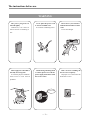
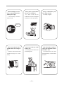
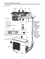
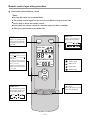
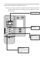
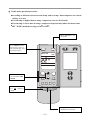
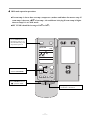
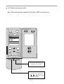
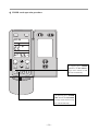
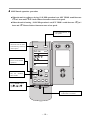
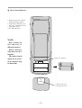
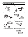
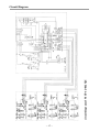
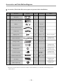
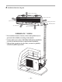
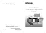
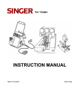
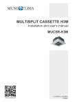
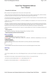
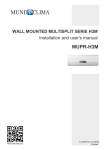
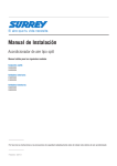
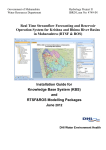
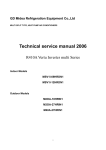
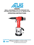
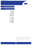
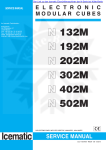
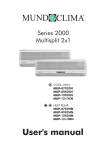
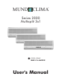
MUND CLIMA
®
Series 2000
Multisplit 3x1
COOL ONLY:
MUP-12+062X2C
User's Manual
The instructions before use
WARNING
The power plug must be
inserted tightly.
Otherwise,it can cause an
electric shockoverheating or
fire.
Never splice the power cord
or use an extended cord.
It can cause overheating or fire.
Don’t insert your hands or
stick into the air intake or outlet
vents.
It can cause danger.
danger
Don’t apply the cold wind to
the body for a long time.
It cause the physical condition
deferioration and health
problems.
When having a burning smell
or smoke,please turn off the
power supply and contact with
the service center.
Don’t use fuse excluding the
fuse of correct capacity.
Improper wire could cause the
break down or fire.
Switch off
Wire
OFF
1
When cleaning,it is necessary to stop driving and turn
off the power suply.
It occasionally cause the
electric shock.
Don’t place a space heater
near the air conditioner.
Air flow from the air
conditioner can cause incomplete
combustion to the space heater.
Keep combustible spray
away from the units.
It is likely to ignite.
Don’t step on the top of the
outdoor unit.
As falling off the outdoor unit
can be dangerous.
Don’t block the air intake or
outlet vents of both the outdoor
and indoor units.
It can decrease the air conditioning capacity or cause a malfunction.
Switch off
OFF
Please note whether the installed stand is firm enough or
not.
It leads to the fall of the unit
causes the injury etc. occasionally.
2
Name and function of each part
Indoor unit
Air in
2
3
1
4
5
9
6
RUN
AUTO
TEST
8
Air out
7
4
STOP
6
12
SET
TEMP.
RUN
SIGNAL
RECEPTOP
Operation indicator (GREEN)light up when the unit is on, and flashing
when the unit is defrosting.
r in
Ai
10
Outdoor unit
11
Air out
3
11
12
Remote control operation procedure
Name and Function-Remote control
Note:
Be sure that there are no obstructions.
The remote control signal can be received at a distance of up to about 10m.
Don’t drop or throw the remote control.
Don’t place the remote control in a location exposed to direct sunlight.
This type is just useful to cool mode only.
FAN button
SWING button
When it is pressed, the
louvers start to rotate automatically and stop when
repressed.
Presse this button to
change the fan speed of:
SWING
AUTO FAN
FAN
AUTO FAN
OPER
AUTO
TEMP.button
SET TEMP.increases 1=by
pressing button once,and
decreases 1=by pressing
button once.
At COOL mode operation,
SET TEMP. can be selected
from 16 to 30.
At DRY mode operation, SET
TEMP. can be selected from
16 to 30.
MODE button
Press this button to change
the operation mode in order of mode morder of
C AIR
SWING HUMID LIGHT SAVE
“
” COOL mode
“
” DRY mode
“
” FAN mode
“
” HEAT mode
TIMER
ON OFF
HR.
1/0 button
Presse this button to turn
on or turn off the unit.
MODE
1/0
AUTO
4
Name and Function-Remote control (Remove the cover)
Note: This type of remote controller is a kind of new current controller.Some buttons
of the controller which are not available to this Air conditioner will not be
described below.
Liquid crystal displayer.
It shows all set contents.
SWING
FAN
AUTO FAN
OPER
AUTO
AIR
SWING HUMID LIGHT SAVE
SLEEP button
Press this button to set
SLEEP operation.
HR.
SLEEP
AIR
LIGHT
HUMID
TIMER ON TIMER OFF ANION
MODE
SAVE
TIMER OFF button
At operating, press TIMER
OFF button, set OFF TIME
in range of 0 to 24 hour to
stop the unit automatically.
1/0
TIMER ON button
At stopping, press TIMER ON
button, set ON TIME in range of
0 to 24 hour to start the unit
automatically.
5
COOL mode operation procedure
=
According to difference between room temp. and set temp., microcomputer can control
cooling on or not.
If room temp. is higher than set temp., compressor runs at COOL mode.
If room temp. is lower than set temp., compressor stops and only indoor fan motor runs.
SET TEMP. should be in range of 16
to 30
K
4.Press FAN button, set
fan speed.
3.Press SWING button,
the louvers start to rotate automatically, and
stop when repress.
SWING
FAN
AUTO FAN
OPER
SWING
5.Press TEMP. button, set suitable SET
TEMP.
SLEEP
AIR
LIGHT
HUMID
TIMER ON TIMER OFF ANION
2.Press MODE button,
set
operation
mode.
MODE
SAVE
1/0
1.Plug in, press 1/0 button,then air
conditioner is turned on.
6
DRY mode operation procedure
If room temp. is lower than set temp., compressor ,outdoor and indoor fan mortor stop. If
=2
of set temp., Air conditioner is drying.If room temp. is higher
room temp. is between=
than set temp. it’s at COOL mode.
SET TEMP. should be in range of 16
to 30
K
=
=
3.Press SWING button,
the louvers start to rotate automatically, and
stop when repress it.
SWING
FAN
AUTO FAN
OPER
SWING
4.Press TEMP.button,set
suitable SET TEMP.
SLEEP
AIR
LIGHT
HUMID
TIMER ON TIMER OFF ANION
2.Press MODE button,set
operation mode.
MODE
SAVE
1/0
1.Plug in,press 1/0 button,then air
conditioner is turned on.
7
AUTO mode operation procedure
for COOL mode .
At AUTO mode operation, standard SET TEMP. is 25
Remote control operation procedure
=
SWING
FAN
AUTO FAN
OPER
AUTO
SWING
SLEEP
AIR
LIGHT
HUMID
TIMER ON TIMER OFF ANION
MODE
SAVE
1/0
1.Plug in,Press 1/0 button, then
air conditioner is turned on.
2.According to room temp.,microcomputer can automatically set
===== operation mode,
so as for best effect.
11
8
TIMER mode operation procedure
SWING
FAN
AUTO FAN
SWING
TIMER
ON OFF
HR.
SLEEP
AIR
HUMID
LIGHT
TIMER ON TIMER OFF ANION
MODE
At stopping,press TIMER
ON button, set ON TIME in
range of 0 to 24 hour to start
the unit automatically.
SAVE
1/0
At operating,press TIMER
OFF button.set OFF TIME
in range of 0 to 24 hour to stop
the unit automatically.
9
SLEEP mode operation procedure
When the unit is cooling or drying, if SLEEP operation is set, SET TEMP. would increase
in 2 hour. Indoor fan motor runs at low speed.
1
in 1 hour and 2
Iin 1
When the unit is heating , if SLEEP operation is set,SET TEMP. would decrease 1
hour and 1
2 hours. Indoor fan motor runs at low speed.
4.Press FAN button, set
fan speed.
3.Press SWING button,
the louvers start to rotate
automatically, and stop
when repress.
SWING
FAN
AUTO FAN
6.SLEEP button
Press it to set SLEEP
operation.
5.Press TEMP. button, set suitable
SET TEMP.
OPER
SWING
SLEEP
AIR
LIGHT
HUMID
TIMER ON TIMER OFF ANION
2.Press MODE button,
set
or
operation mode.
MODE
SAVE
1/0
1.Plug in, press 1/0 button,then air
conditioner is turned on.
10 How to insert batteries
1. Remove the cover from the
back of the remote control.
2. Insert the two batteries ( Two
AAA dry - cell batteries ) and
press button “ACL”.
3. Re - attach the cover.
NOTE:
Don’t confuse the
new and worn or
different batteries.
Remove batteries
when not in use for a
longtime.
The remote control
signal can be received at a distance of up
to about 10m.
2.Insert the 7# batteries
ACL
OPEN
1. Remove the cover
3. Re-attach the cover.
11 14
USER NOTICES
Note:The climate type is (18
43
Select the most appropriate temperature.
The air flow direction can be adjusted appropria-
It can preclude the electricity wasted.
tely.The louvers can be adjusted downward at heating operation, and upward at cooling operation.
COOL
L
O
CO
Don’t leave windows and doors open while
operating the air conditioner for a longtime.
It can decrease the air conditioning capacity.
Don’t blow the wind to animals and plants directly.
It can cause a bad influence to them.
Splashing water on the air conditioner can cause
an electric shock and mal-function.
The ground must be connected.
Don’t connect the earth wire to gas or water pipes.
lightning rods or telephone earth lines.
Air conditioner should be operated with stable
voltage in range of 206-244V 1ph.otherwise,
compressor would vibrate terribly,to damage
refrigeration system.
Don’t use the air conditioner for other purposes,
such as drying clothes, preserving foods, etc.
50Hz
220-230V
12 Care and Maintenance
CAUTION
Turn power off and pull out the power plug before cleaning air conditioner.
Don’t sprinkle water on the indoor unit and the outdoor unit for cleaning.
Wipe the units with a dry soft cloth, or a cloth slightly moistened with water or cleanser.
Cleaning surface panel
1. Pull along the direction of arrows to take down surface
panel.
2. Washing
Wipe with a cloth slightly moistened with water or
cleanser, and then dry it in the shade.
NOTE: Never use water above 45 to wash the panel,
or it could cause deformation or discolouration.
3. Install surface panel
Cover the surface panel and clasp it.
Cleaning the Air Filter (Recommended once every three weeks)
1. Open the surface panel,hold the tab of Air Filter and
raise it slightly, and then take it out.
Slot
Air Filter
2. Cleaning
To clean the dust adhering to the filters, you can either
use a vacuum cleaner, or wash them with water and dry
it in the shade.
NOTE:
Never use water above 45
to wash the filters, or
it could cause deformation or discolourtion.
13 3.Reinsert the filters
Reinsert the filters with side marked “FRONT”
facing forward.
Replacement of Air cleaner
=Recommended once every Six months,and the alternate filters can be found in the service center.
1.Remove the Air Filters
(Refer to the first step of “cleaning the Air Filters”)
2.Replace the Air cleaner
Take off the packed bag of Air purifying Filters,and
then put new Filters into the Filter frame.
Air cleaner
NOTE:Be careful not to injure yourself on the fins
(Refer to the third step of “cleaning the Air Filters”)
3.Reinsert the filters.
Preparation before use
1.Be sure that nothing obstructs the air outlet and intake vents.
2.Check that whether ground wire is properly connected
or not.
3.Replace filters if necessary.
4.Turn main power on at least 6 hours before starting
actual operation.This will ensure a smooth starting
of the units.
Maintain after use
1.Clean filters and other parts.
2.Turn main power off.
3.Clean dust from the outdoor unit.
4.Repaint the rubiginous place on the outdoor unit to
prevent it from spreading.
14 Troubleshooting
Check the following before requesting on service center if the malfunction occurs.
Phenomenon
Waitting
Trouble Shooting
Indoor unit does not
operate immediately
when the air conditioner is restarted.
Once the air conditioner is stopped, it will not operate in
approximately 3 minutes to protect itself.
There’s unusual smell
blowing from the outlet after operation is
started.
This is caused by the odors in the room which have been
breathed into the air conditioner.
Sound of water flow
can be heard during
operation.
This is caused by the refrigerant flowing inside the unit.
Mist emitted during
cooling operation.
Because the air of the room is cooled down rapidly by the
cold wind and it looks like the fog.
Creaking noise can
be heard when start
or stop the unit.
This is caused by the deformation of plastic due to the
change of temperature.
Air conditioner
does not operate
at all.
OFF
. Has the power been shut down?
. Is the wiring loose?
. Is the leakage protection switch in operation?
. Is voltage higher than 244V or lower than 206V?
. Is TIMER ON in operation?
OFF
Cooling efficiency is
not good.
Wireless remote controller is not available.
. Is SET TEMP. suitable?
. Is air inlet or outlet obstructed?
. Are air filters dirty?
. Is indoor fan speed set at low speed?
. Is there any other heat sourse in your room?
. Is the remote control unit out of effective distance to
the indoor unit?
. Replace the worn batteries of wireless remote
controller.
. Are there any obstructions between the wireless remote controller and the signal receptor?
15 Immediately stop all operations and plug out,contact with service center.
Unusual noise can be heard during operation.
Power fuse or switch often breaks.
Carelessly splash water or something into air conditioner.
Electrical lines and power plug are very hot.
Wind blowing from the outlet smells terrible during operation.
16 circuit diagram of MUP-12+062X2C
Circuit Diagram
17 Accessories and Installation diagram
Accessories (Check that all accessory parts are present before installation)
No.
Part name
1
Rear panel
N
2
Wireless remote controller
N
3
Battery
O
7# 1.5V
4
Power connection cord
N
YZW300/500
3 2.5
5
Control cord
Q
4G 1.0
6
Tapping screw
NM
ST4.2 25
Fix the rear panel
7
Plastics drain hose
N
L = 2m
Packaged with
connection piping
8
Gum type sealer
N
120 65 25
9
Piping-hole sleeve
N
10
Wrapping tape
O
11
Connection piping
N
12
Thermal insulation hose
N
13
Air cleaner
O
Packaged with
indoor unit
14
Plastic square ring
N
Packaged with
Outdoor unit
Diagram
Qty
specification
Memo
Packaged with
connection piping
30 10
6/
9.5
Packaged with
connection piping
Packaged with
connection piping
35 500
* Be sure to use the exclusive accessories list above in the installation, or it will lead to water leakage ,electric
shock, fire,etc.
18 Installation dimension diagram
15cm or more
15cm
Space to the ceiling
Space to the wall
or mo
re
ore
15cm or m
Space to the wall
Piping -hole sleeve
Space to the floor
230cm or more
30cm
Air outlet side
or m
ore
Wrapping tape
IMPORTANT NOTES
* The installation must be done by trained and qualified service
50cm or more
personnel with reliability according to this manual.
* Contact with service center of MUNDOCLIMA before installation
to avoid the mal-function due to unprofessional installation.
* When picking up and moving the units, you must be guided by
trained and qualified personnel.
Space
30cm or
more
to the
wall
re
r mo
o
cm
200 Air ou
tlet si
19 de
Space
to the c
over
he
to t
e
e
ac
Sp or mor
m
30c
ll
wa
Installation location
Indoor unit
1. The inlet and outlet should not be covered so that the outflow air can reach all parts of the room.
2. Install in a location where is permitting easy connection with the outdoor unit.
3. A location from which the condensation water can be drained out conveniently.
4. Avoid a location where there is heat source, high humidity or inflammable gas.
5. Install in a location where is strong enough to withstand the full weight and vibration of the unit.
6. Be sure that the installation conforms to the installation dimension diagram.
7. Be sure to leave enough space to allow access for routine maintenance.
8. Install in a location where is lm or more away from other electric appliances such as television, audio device, etc.
9. Select location where is easy to remove and clean the filter.
10.Be sure that the distance from the location to the ground is more than 2.3m.
Outdoor unit
1. Select location from which noise and outflow air emitted by unit will not inconvenience neighbors.
2. Select location where there should be sufficient ventilation.
3. The inlet and outlet should not be covered.
4. The location should be able to withstand the full weight and vibration of the outdoor unit.
5. There should be no danger of flammable gas or corrosive gas leaks.
6. Be sure that the installation conforms to the installation dimension diagram.
NOTE:
Install in the following place may cause mal - function. If it is unavoidable, contact with service center of
MUNDOCLIMA please.
Place where oil (machine oil ) is used.
The place where a lot of salinities such as coast exists.
Place where a sulfured gas such as the hot spring zones is generated.
Place where high - frequency waves are generated by radio equipment.welders and medical equipment.
Other place with special circumstance.
H 2S
20 Install the indoor unit
Install the rear panel
1.Always mount the rear panel horizontally.
2.Fix the rear panel on the selected location with
screws supplied.
3.Be sure that the rear panel has been fixed firmly
enough to withstand the weight of an adult of
60kg, furthermore, the weight should be evenly
shared by each screw.
Install the drain hose
1.For well draining, the drain hose should be
placed at a downward slant.
2.Do not wrench or bend the drain hose or flood
its end by water.
Install the piping hole
1.Make the piping hole ( 65) in the wall at a
slight downward slant to the outdoor side.The
center of the hole should be determined refer to
Fig.2.
2.Insert the piping - hole sleeve into the hole to
prevent the connection piping and wiring from
being damaged when passing through the hole.
Wrenched
Bent
Flooded
Install the connection pipes
Connect the connection pipes with the relevant union pipes of the indoor unit (Shown in P27=Pipe connection” )
NOTE:
Connect the connection pipes with the indoor unit firstly and the outdoor unit secondly.
Be careful in bending the connection pipes, or you will damage the pipes.
If the tightening torque is too great in tightening the flare nuts, leakage will happen.
Electrical wiring
1. Open the surface panel.
2. Remove the wiring cover.
3. Route the power connection cord from the back of the indoor unit and pull it toward the front throught the wiring
hole for connection.
4. Connect the blue wire of the power connection cord to the terminal “ N(1)”,the brown one to“ 2”, the red one to“ 3”,
and the yellow- green one ( earth wire ) to “
’’ as shown in Fig.3.
5. Reassemble the wiring cover.
6.Recover the surface panel.
21 Wiring cover plate
N(1)
2
3
Power connection cord
(Fig.3)
NOTE:
All the electrical work must be done by qualified personnel according to the local rules and this manual.
The rated voltage and the exclusive circuit must be used.
Leakage circuit - breaker must be installed.
Please use specified fuse.
The diameter of power cord should be large enough.Use the cxclusive wire to replace the damaged wire.
Wiring work should conform to national standard.
Switches shall be connected to the supply teminals and shall have a contact separation of at least 3mm in each
pole.
Install the indoor unit
1.When routing the piping and wiring from the left or right
side of the indoor unit, cut off the tailings from the chassis
in necessary (shown in Fig.4)
Cut off the tailingsl when routing the wiring only.
Cut off the tailingsl and tailings 2 when routing both the
wiring and piping.
Tailings3
Tailings2
Tailings1
(Fig.4)
2.Wrap the piping and wiring and pull them through the cutoff -tailings hole (shown in Fig. 5).
Power connection cord
Drain hose
control cord
3.Hang the 2 mounting slots of the indoor unit on the upper
tabs of the real panel and check if it is firm enough.
Connection pipes
Wrapping tape
4.The height of the installed location should be 2.3m or more
from the floor.
22 (Fig.5)
Install the outdoor unit
Installing the unit
BE Sure to fix unit’s legs with bolts when installing it.
Be sure to install the unit firmly to ensure that it does
not fall by an earthquake or a gust.
Refer to the figure in the right concrete foundation.
=
Fix here with
M10 botls
=
=
NOTE
The length of anchor bolts should be within 25mm
from each anchor leg.
Make the setting
depth deeper
Make with wider
Be sure to carry out drain piping work following the
installation manual.
If there is some deficiency in draining and pinping work,
it may cause a risk of dripping from the unit,wetting or
fouling your property.
572
310
CAUTION:
25mm or less
Anchor leg
Anchor both length
Anchor both pitch
How to remove the service panel
=
Remove the four service panel securing screws,and
pull the panel down in an arrow direction to remove
the service panel.
Service panel
<Right side view>
<Front view>
Liquid
Gas
Liquid
Gas
Liquid
Gas
23 A UNIT
B UNIT
C UNIT
Indoor/outdoor wire connection and outdoor power supply cord connection
Connect wire from the indoor unit correctly to the terminal block.
For aftercare maintenance.give extra length to connecting wire.
=
=
Indoor unit
Outdoor unit
Rated voltage
220230V
220230V
Breaker capacity
10A
25A
Power supply cord
4G1.0
3 2.5
Note: Be sure that the plastic square rings are tightly installed in the holes of the rear panel to protect
the connection cords and the thermal insulation hose are tightly wrapped the connetion cords
near the rear panel in case of leakage of electricity and rain water.
Loosen terminal screw
Teminal
block
Lead wire
<Connection details>
CAUTION:
=
=
Be careful not to make mis-wiring.
Firmly tighten the terminal screws to prevent them from loosening.
After tightening,pull the wires lightly to confirm that they not move.
If the connecting wire is incorrecty connected to the terminal block,the unit does not operate normally.
Switches shall be connected to the supply teminals and shall have a contact separation of at least 3 mm in
each pole.
==
=
=
WARNING:
Be sure to attach the terminal block covers/panel of the outdoor unit securely.if it is not attached correctly,it could result in
fire or an electric shock due to dust,water,etc.
Cable clamp
Power supply cord
Indoor unit connection wire
24 Indoor/outdoor units connection finishing and test run
Pipe length and height difference
Limits
UNIT NO.
A
B
C
pipe length per
20 m max.
20 m max.
20 m max.
indoor unit
Total 30 m max.
Total 30 m max.
Height difference
10 m max.
10 m max.
10 max.
No.of bends
10 max.
10 max.
Total 15 max.
Total 15 max.
Refrigerant adjustment... If pipe length exceeds 10 m, additional refrigerant (R22) charge is required.
(The outdoor unit is charged with refrigerant for pipe length up to 10 m.)
==
A unit + B unit
C unit
Pipe length (one-way)
Refregerant to be added
Refregerant to be added
10 m or less
No additional charge
No additional charge
10J30m
10 g/m
10 g/m
Indoor unit A and B or C are in the same refrigerant cycle system, so please add enough refrigerant to run both units A and
B or C.
==
Selecting pipe size
The diameter of connection pipes differs according to the type and the capacity of indoor units, Match the diameters
of connection pipes for indoor and outdoor units according to the following table.
Valve size for outdoor unit.
Valve size for outdoor unit
A UNIT
B UNIT
C UNIT
Liquid pipe
6 mm
Gas pipe
9.52 mm
Liquid pipe
6 mm
Gas pipe
9.52 mm
Liquid pipe
6 mm
Gas pipe
9.52 mm
Piping preparation
Table below shows the specifications of pipes commercially available.
Pipe
Outside diameter
Insulation thickness
Insulation thickness
For liquid
6 mm
8 mm
For gas
9.52 mm
8 mm
Heat resisting foam plastic
0.045 specitic gravity
Ensure that the 2 refrigerant pipes are insulated to prevent condensation.
Refrigerant pipe bending radius must be 100 mm or more.
CAUTION:
Be sure to use the insulation of specified thickness, Excessive thickness may cause incorrect installation of
the indoor unit and lack of thickenss may cause dew drippage.
25 Flaring work
Main cause of gas leakage is defect in flaring work.
Perform flaring work correctly in the following procedure.
1.Pipe cutting
Cut the copper pipe correctly with pipe cutter.
Copper pipe
Good
90
2.Burrs removal
Completely remove all burrs from the cut cross
section of the pipe.
Put the end of the copper pipe downward to
prevent burrs from dropping in the pipe.
Burr
Tilted Uneven Burred
Copper pipe
Spare reamer
Pipe cutter
3.Putting nut on
Remove flare nuts attached to indoor and
outdoor units,then put them on pipe having
completed burr removal.
(not possible to put them on after flaring work)
Flare nut
Copper pipe
4.Flaring work
Perform flaring work using flaring tool as
shown in the right.
Flaring tool
A
Yonk
Die
Pipe diameter
A ( mm)
For rigid
Die
Copper pipe
For imperial
6 mm
2.0 to 2.5
0.5
9.52 mm
3.0 to 3.5
0.5
Flare nut
Copper pipe
Firmly hold copper pipe in a die in the dimension shown in the table above.
5.Check
Compare the flared work with figure in the right.
If flare is noted to be defective,cut off the flared section and perform flaring work again.
Smooth all around
Inside is shining without any scratches
Too
much
Sctatch
on flared
Tilted plane Cracked Uneven
Even length
all around
Pad examples
26 Pipe connection
Indoor unit connection
Connect both liquid pipe and gas pipe to indoor unit.
Apply a thin coat of refrigeration oil to the seat surface of pipe.
For connection, align the center of both pipe and union, then tighten the first 3 to 4 turns in flare nut by hand.
For tightening the union part of the indoor unit side, use the table below as a standard and tighten the flare section.
Tightening torque
Pipe diameter
mm
N.m
kgf.cm
6.35 mm
13.7 to 17.7
140 to 180
9.52 mm
34.3 to 41.2
350 to 420
Outdoor unit connection
Connect pipes to the pipe joint part of the stop valve in the same method as the indoor unit.
For tightening,use the same tightening torque applied for indoor unit and tig then the flare nut with torque wrench or
spanner.
Insulation and taping
Cover piping joints with pipe cover.
For outdoor unit side, surely insulate every piping including valves.
Using piping tape, apply taping starting from the entry of outdoor unit.
Fix the end of piping tape with adhesive tape.
When piping has to be arranged through above ceiling, closet or area where the temperature and humidity are high,wind
additional commercially sold insulaton for prevention of condensation.
27 Air purge and leak test
=
=
=
For details about how to use manifold valves, see the
instruction manual for manifold valves.
The handle Hi below connect operate during the following
work if it is fully closed.
Evacuate every indoor unit for rooms AB and C.
Pressar gage
Comperad powere gage
Mite
Hande Lo
Hande Hi
Make sure the pipes have been connected properly.
Connect the manifod valve to the service port of the stop
valve (3- way valve) by using a charge hose.At this time,
the inside-core end of the charge hose must be connected
to the service port.
Make sure the stop valve (2-way and 3-way valve) are fully
closed. and then connect another charge hose to a vacuum
pump.
Fully open the handle Lo on the manifold valve, and then
run the vacuum pump.
Loosen the flare nut of the stop valve (3-way valve) slightly
to make sure that air is entering it.
Then, retighten the flare nut.
(If air is not entering it, make sure again the charge hose is
fimly connected to the service port.)
Evacuate the circuit for 15 minutes or more,and make sure
that the compound pressure gage reads-760 mm Hg.
After finishing the evacuation.fully close the handle Lo on
the manifold valve. and then stop the vacuum pump.
Fully open the stop valve (2-way and 3-way valves) by
turning the valve rods to the left until they stop When the
rods contact the stoppers. do not apply force any more.
Tighten the valve rod caps for the stop valves (2-way and
3-way valves).
Leak test
Using soapy water. perform the leak test for both the indoor
and outdoor sides,Make sure no bubbles appear on the
connections. If bubbles appear they indicate gas is leaking
from that point.
If gas is leaking
Tighten the flare nut connection more strongly.
If it has no effect.repair any existing leak points,release all
gas from the service port completely,and then recharge the
specified amount of refrigerant gas from cylinder.
Cap for service port
Cap for stop valve
Tightening torque
N.m
kgf.cm
13.7 to 17.7
140 to 180
19.6 to 29.4
200 to 300
28 Charge
bose
In the case of gas leakage
Tighten the flare nut connections.
If this tightening does not help stopping the leakage
repair the leak portion (s).remove the gas from the
service port, refill the specified amount from the
cylinder gas.
WARNING:
When installing or moving the unit, do not mix
anything other than specified refrigerant (R22) into
the refrigerating cycle.
If air is mixed,it may cause the refrigerating cycle to
get abnormally high temperatre, causing a risk of
burst.
For movement and maintenance
1 How to install the panel
Before installing the panel, set the horizontal vane to the position as shown below.
Insert the bottom of the panel under the horizontal vane.
Set the top of the panel.
Push the panel as the arrow mark to fix to the air conditioner.
(3)
(4) Push
(2)
1) Horizontal vane
(slightly downward)
Horizontal vane
2 Removing the indoor unit
Remove the bottom of the indoor unit from the installstion plate.
When releasing the corner part
Release both left and right bottom corner part of indoor unit and pull it downward and forward as shown toto release the
hooks.
If the above method cannot be used
Remove the front panel and insert hexagonal wrenches into the square holes on the left and right as shot the figure below,
then push them up; the bottom of the indoor unit is lowered and the hooks are released.
Squarc hole
29 Push
Lowers
Gas charger
Perform gas charge to unit A or B and unit C
Connect gas cylinder to the service port of stop valve.
Perform air purge of the pipe (or hose) coming from refrigerant gas cylinder.
Replenish specified amount of the refrigerant, while operating the air conditioner for cooling.
CAUTION:
Never charge liquid refrigerant, such as by inverting the gas cylinder while charging, otherwise troubles may be generated.
To maintain the high pressure of the gas cylinder, warm the gas cylinder with warm water (under 40 ) during cold
season, But never use naked fire or steam.
Refrigerant pipes
Indoor unit
6
9.52
A UNIT
B UNIT
Union
Service port
6
9.52
C UNIT
Refrigerant gas cylinder
operating valve
Slop valve
Refrigerant gas
cylinder
Charge hose
Scale
(R22 gas) Gas change
30 6
9.52
Outdoor unit
CONTENT
The instructions before use
1
Name and function of each part
3
Remote Control operation procedure
Operation and maintenance
Name and function-Remote control
4
Name and function-Remote control (Remove the cover)
5
COOL mode operation procedure
6
DRY mode operation procedure
7
AUTO mode operation procedure
8
TIMER mode operation procedure
9
SLEEP mode operation procedure
10
HOW to insert batteries
11
Installation
User notices
12
Care and Maintenance
13
Troubleshooting
15
Circuit diagram
17
Accessories and installation diagram
18
Installation location
20
Install the indoor unit
21
Install the outdoor unit
23
Indoor/outdoor wire connection and outdoor power supply cord connection
24
Indoor/outdoor units connection finishing and test run
25
Flaring work
26
Pipe connection
27
Air purge and leak test
28
For movement and maintenance
29
Gas charger
30
Thank you for choosing MUNDOCLIMA Air conditioner, please keep this owner’s manual carefully for consultation.
31