1
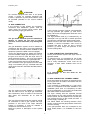
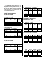
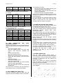
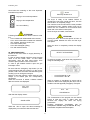
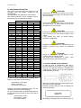
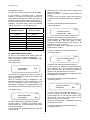
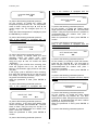
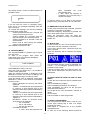
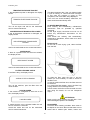
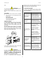
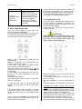
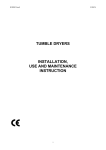
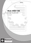
04/2012
Mod: DSE-14
Production code: ES14-ELETTRICO
E100301X_ENG
31/05/10
Index
1. INTRODUCTION ........................................................................................................................................... 3
2. SAFETY RULES ............................................................................................................................................ 3
3. MANUFACTURER RESPONSABILITY ........................................................................................................ 4
4. UNPACKING ................................................................................................................................................. 5
5. MACHINE IDENTIFICATION ........................................................................................................................ 5
6. INSTALLATION AND POSITIONING ............................................................................................................ 5
7. INSTALLATION: GAS HEATED DRYERS .................................................................................................... 6
8. INFORMATION ABOUT MACHINE NOISE. ................................................................................................. 6
9. ELECTRIC CONNECTION ............................................................................................................................ 6
10. GAS CONNECTION .................................................................................................................................... 8
11. GAS CONNECTION: TIGHTNESS TEST ................................................................................................... 8
12. GAS CONNECTION: THERMAL POWER .................................................................................................. 8
13. GAS CONNECTION: GAS INLET PRESSURE CONTROL ..................................................................... 10
14. GAS CONNECTION: FINAL TEST ........................................................................................................... 10
15. HUMID AIR AND BURN GAS EXAUST .................................................................................................... 10
16. STEAM CONNECTION ............................................................................................................................. 10
17. COMPRESSED AIR CONNECTION ......................................................................................................... 11
18. TO USE THE DRYER ............................................................................................................................... 11
19. PREPARE THE LINEN .............................................................................................................................. 11
20. PROGRAM START ................................................................................................................................... 12
21. PROGRAM DELAYED START ................................................................................................................. 13
22. PROGRAM PAUSE ................................................................................................................................... 14
23. PROGRAM STOP ..................................................................................................................................... 14
24. PROGRAM STEPS ................................................................................................................................... 14
25. END OF A WORKING DAY ....................................................................................................................... 15
26. MODIFICATION OF THE PARAMETER DURING THE CYCLE .............................................................. 15
27. MANUAL WORKING ................................................................................................................................. 15
28. PROGRAMS DESCRIPTION .................................................................................................................... 16
29. COIN OP DRYER: HOW IT WORKS ........................................................................................................ 16
30. ENTERING IN THE PROGRAM AREA ..................................................................................................... 17
31. PROGRAMS MODIFICATION .................................................................................................................. 18
32. LANGUAGE SELECTION ......................................................................................................................... 20
33. DATE/TIME MODIFICATION .................................................................................................................... 20
34. ENERGY CONSUMPTION ....................................................................................................................... 20
35. NO WRINKLE ............................................................................................................................................ 21
36. INITIAL COOLING ..................................................................................................................................... 21
37. PAYMENT SYSTEM.................................................................................................................................. 21
38. ADVERT .................................................................................................................................................... 21
39. COIN BOX MENU...................................................................................................................................... 22
40. EMERGENCY STOP BUTTON ................................................................................................................. 22
41. BLACK OUT .............................................................................................................................................. 22
42. WHAT MUST BE DONE IN CASE OF GAS SMELL................................................................................. 22
43. DISPLAYED WARNING ............................................................................................................................ 22
44. DRYER MAINTENANCE ........................................................................................................................... 24
45. DRYING PROBLEMS ................................................................................................................................ 25
46. DUAL TIMER DRYER: USE ...................................................................................................................... 26
47. TILTING DRYER: USE .............................................................................................................................. 26
48. SAFETY DEVICE CONTROL.................................................................................................................... 27
49. SCRAPPING.............................................................................................................................................. 27
50. WARRANTY CONDITION ......................................................................................................................... 27
2
1. INTRODUCTION
This manual refers to industrial tumble dryers
installation, use and maintenance.
It is written in compliance with the European
Community rules in force. The information here
written are addressed to the installer and the user,
who must be sure to fully understand them before
to use the machine.
This manual must always be available for
consultancy. In case it should be lost or damaged,
ask for a new copy to the manufacturer.
The producer is not responsible for any
consequence coming from a wrong dryer use
because of a not complete or missing reading of
this manual.
The manufacturer reserves itself the right to
modify the specifications written in this manual or
the characteristics of each machine. Some picture
of this manual may differ from reality because of
some detail. Diagram and technical data may be
changed without any previous notice.
Manual and its attachments are parts of the
machine themselves, so they must be kept
together with the machine and follow the machine
when it is sold to another user.
Attachments and exploded view with spare parts
list can be retrieved in the technical area of the
producer website.
Dryer serial number must be available when
entering in the web site.
ATTENTION!
Manufacturer is not responsible for any possible
wrong information here written, when this errors
are due to a printing or translation error.
The manufacturer reserves himself the right to
modify the product, when necessary or useful,
without changing the main characteristics. Without
any previous authorisation of the manufacturer, to
copy completely or partially the text and the
pictures of this manual is forbidden.
2. SAFETY RULES
Not respecting the following instruction, may
cause damages to people, things and animals.
Installation and maintenance of the here
described machines must be trained by
authorised personnel, which knows the product
and respecting the European Rules in matter of
industrial machines installation.
Reparation made in a not correct way may
seriously compromise the user safety.
Instruction must be read with high attention before
to make the machine work. Instruction must be
available to all the people working with the dryer.
Here described tumble dryers must be used to
professionally drying clothes and linen: any other
use is forbidden, if not before authorized by the
manufacturer.
Before to take out the linen from the dryer, be
sure that the drum is stopped. Never pull your
hands inside the drum, if it is still rotating.
Do not dry in the machine any other different
object; do not dry linen, which entered in contact
with dangerous stuff like explosives, detonating
explosives or inflammables. Linen entered in
contact with this substances, need to be rinsed or
aired before to be dried.
Do not dry linen which has been soaked in
substances dangerous for the operator health, like
poison or cancerogenic stuff.
To avoid risks of fire or explosion, do not
approach to the machine with combustible or
inflammable substances.
Always stick to the drying instruction written on
linen label.
The use of this machine is forbidden to people
under 16 years of age.
External supplementary connection to the
machine release the manufacturer from any
responsibility if they are not properly done.
IMPORTANT NOTES
Working with opened sides is forbidden!
In order to avoid burnings or accident it is
forbidden to remove, even temporarily, the
protection panels and the safety systems!
It is forbidden to introduce bars, sticks or
metallic objects inside the drum.
In case of emergency, please follow always
the here described procedures.
Each time the dryer is starter, check always
the safety device correct working!
To know the machine and its safety device
working is compulsory!
E100301X_ENG
31/05/10
BURNS DANGERS
The dryers, because of its nature, presents a
burns danger.
Burns may be caused by:
- The contact with the linen taken out from
the dryer;
- The contact with the door inside, following
its opening;
- The contact with the heating batteries
during the maintenance;
- The contact with the fluxing steam parts.
400V
OPERATOR PSYCHO-PHYSICAL
CONDITIONS
The dryer user must be in perfect psycho-physical
condition; during the working cycle, the user must
always assume a vertical posture in front of the
machine.
Suddenly or not controlled movement must be
avoided because of the risks of dangerous knocks
against the dryer chassis, i.e.: during the dryer
unloading.
The other people in the laundry room do not have
to distract the operator, who is working on the
dryer.
While working, the operator do not have to be
distracted by TV, radio or any source of
distraction.
On the machines are fixed the following label,
if one of them should be damaged, the user
must replace it with a new identical one.
Stuck near dried linen exit.
LIGHTING
In the room where the machine is installed, the
lighting must be at least of 300-500 lux intensity;
unpleasant flashing must be avoided.
Dryer must always be used by trained
personnel and with at least one other operator
in the room!
ATTENTION!
These instructions do not cover all possible risks.
User must always pay high attention and respect
carefully the rules.
READ CAREFULLY THE INSTRUCTION FOR
OPERATING IN CASE OF BLACK OUT, AND
INFORM ALL THE USER ABOUT THEM.
3. MANUFACTURER RESPONSABILITY
The instructions written in this manual are not
replacing, but completing the duties deriving from
the safety and accident prevention laws.
With reference to what is written in this manual,
the manufacture is not responsible for:
- a use of the machine against the safety and
accident prevention laws in force.
- not correct machine installation.
- missing of periodical and programmed
maintenance.
- not observance, or not correct observance, of
this manual instructions.
- electrical supply fault.
- not authorized modification of the machine.
- use of the machine by not authorized
personnel.
ELECTROCUTION DANGER
Any service on the electrical parts must by
operated only by qualified personnel. Before
to work on the machine, cut off the electrical
supply.
Power and controlled circuits can be modified
only by manufacturer personnel, on the
contrary the warranty condition empire.
On the electric board, the here below warning
label was stuck. If this label should be damaged
or unstuck, it needs to be replaced by an identical
one.
4
E100301X_ENG
31/05/10
4. UNPACKING
The machine must be controlled at the delivery
moment, any external or inside damage dues to
the transport, must be reported immediately to the
forwarder.
ATTENTION!
Moving the machine, remember that the dryer
centre of gravity is located in the last third of the
machine height.
Machine must be completely unpacked next to the
installation place. Straps must be cut and the
covering packing material must be taken off.
Packing materials must be wasted following the
rules in subject of environment protection.
Using a key, take away the nuts on the machine
base which are fixing the dryer to the pallet
(frontal and back).
If the sticker is damaged or partially/completelly
missing, the dryer cannot be correctly identified,
so that any installation or maintenance job can be
difficult. In the above case the warranty
automatically and immediately expires.
ATTENTION!
Check the machine net and gross weight on the
technical data sheet sent with the machine: it
must comply with the available lifting means.
ATTENTION!
Pallet cannot be used as normal dryer support!
The machine must always be installed without the
pallet and positioned as described in the relative
paragraph.
6. INSTALLATION AND POSITIONING
Installation must be trained by qualified personnel.
Machine must be positioned on a plane surface
horizontally and in a stable way using the
adjustable feet at the dryer base.
Feet can be adjusted from outside, screwing and
unscrewing them until the dryer is correctly
positioned.
In models where it is provided, the feet can be
adjusted from inside using a 5mm hexagonal key
after the filter door and the back panel have been
opened
ATTENTION!
The machine can be moved only when it is fixed
on its pallet: the machine handling must be done
only by trained and competent personnel.
5. MACHINE IDENTIFICATION
Each dryer can be identified by the sticker with
reporting the dryer serial number, model, power
and technical characteristics.
Be sure that the exiting supply systems (electric,
hydraulic, steam, gas, compressed air) are
complying with the data written on this sticker.
Spare parts and service can be supplied only if
the dryer, to which they are addressed, is
correctly identified.
5
E100301X_ENG
31/05/10
Always check if the floor can bear the machine
weight written in the technical data sheet.
The machine load can be considered completely
static. To calculate the dryer static load,
remember to add the weight of the wet linen
introduced in the dryer to the dryer net weight.
Remember to leave at least 500mm around the
machine to grant a correct dryer use, working and
maintenance.
The room temperature must be between +5°C
and +40°C.
The room where the machine is installed, must
have enough air change. Please note that the
machine take air from the room where it is
installed and that the humid air coming from the
drying cycle must be exhaust outside.
In case a liquid gas heated dryer should be
installed below the ground level, adequate device
for a forced ventilation must be provided.
ATTENTION!
Never installed a gas heated machine in the
same room where machine using solvents are
installed (example: dry cleaning machine) .
This combination could produce dangerous
substances for the operator and it can cause
steel corrosion.
If a gas heated machine and a machine using
solvents are installed in two separate room, be
sure that there is no possibility of air
exchange between the two rooms.
ATTENTION!
Clean air must be assured to the machine; air
combined with chlorine, fluorine or other
solvent vapours must be avoided.
ATTENTION!
In case of machine equipped with a tilting
system, the machine must be fixed to the floor
using some screw anchor.
Do not use or stock near the machine
benzene, petroleum or other inflammable
stuffs. On the contrary fire or explosion may
be caused.
Machine
must
be
installed
perfectly
horizontally on a floor without elastic reaction.
Keep near the machine a foam extinguisher
which is periodically controlled in compliance
with the rules in force.
ATTENTION!
In case of titling machines, there are external
parts which moves during the linen loading
and unloading steps.
For machine dimensions and machine needed
space during the movement, please refer to
the technical data sheet.
7. INSTALLATION: GAS HEATED DRYERS
Each gas heated machine must be considered,
independently from the capacity, a gas
equipment.
During the installation, the following rules must be
respected:
- territorially building and fire-prevention rules;
- accident prevention rules;
- CENELEC rules (electric system);
- Rules about the combustible gas use
- Rules about gas system supplied by public
net or GPL gas
- Rules coming from the gas company
- Rules coming form the electricity company
- Other possible local rules.
Room air inlet and ventilation opening can be
closed only if the closing condition is controlled
and if the gas equipment is allowed to work only
when they are opened.
The room is correctly aired, also in case of the
exhaust gas are mechanically sucked, when the
nominal thermal pollution of this gas equipment do
not cause depression in the room.
In this way a regular gas combustion and the
complete exhaust of the burn gas are guaranteed.
To dimension the air grating, please refer to the
data written on the machine technical sheet and to
the rules in force.
8. INFORMATION ABOUT MACHINE NOISE.
The air noise produced by the machine is
producing an A continuous and weighted acoustic
pressure lower then 70 dB.
In case that more machine should be mounted in
line, the sums of the acoustic pressure are:
2 machines: air noise < 73dB
3 machines: air noise < 75dB
4 machines: air noise < 76dB
5 machines: air noise < 77dB
9. ELECTRIC CONNECTION
Electric connection must be carried out by
qualified technicians and must comply with local
and national rules in force.
To connect the machine use a H05 VV – F cable
or superior, it must be correctly dimensioned
following the data label.
Install before the machine a omnipolar
disconnecting device (i.e.: a circuit breaker) which
need to have a contact opening that allows the
complete disconnection in case one of the
conditions of the over tension III category is
6
E100301X_ENG
31/05/10
verified. This device must comply with the subject
regulation in force.
Check the main switch, it must be in position “0”.
Open the electric supply door.
Pass the electric supply cable through the cable
holder supplied with the machine. The cable must
be correctly dimensioned (check the following
table).
Il collegamento dei cavi di alimentazione elettrica
deve essere eseguito sul sezionatore di bordo
macchina.
Be sure the main switch is in position “0”.
Open the electric supply back door. The cable,
which need to have the adequate dimension (see
the following tables), must pass through the cable
holder supplied with the machine.
Electric supply cable connection must be done on
a marked series of terminal.
The minimum section for the electric cable are
2
indicated in the below table (expressed in mm )
SIZE
1ph
208V-240V
3ph
208V-240V
3ph
380V-440V
10
25
10
10
14
25
10
10
18
25
16
10
23
25
16
10
34
35
25
16
55
no
35
25
75
no
50
35
Electric heating
Following the kind of heating, which is indicated
on the serial number plate, connect the cable to
the terminals, as indicated:
SIZE
1ph
208V-240V
3ph
208V-240V
3ph
380V-440V
10
2,5
2,5
2,5
14
2,5
2,5
2,5
18
2,5
2,5
2,5
23
2,5
2,5
2,5
34
2,5
2,5
2,5
55
4
2,5
2,5
75
4
2,5
2,5
: ground, colour: yellow/green
L1, L2, L3: phase, colour: brown
N: neutral, colour: blue
In case of installation or replacement of the
supplying cable, the ground cable must be at least
5cm longer.
Steam or gas heating
ATTENTION!
Check the fan rotation direction: it must rotate in
the direction which allows the exhaust air
discharge; it means that the fan motor must
rotated in the direction indicated by the arrow
marked on the motor cover.
Check that the phases are connected in the
correct sequence.
ATTENTION!
The above minimum sections written above, can
change following the connection cable length. For
a cable long more then 5mt, increase
proportionally the section in function of the added
length.
The machine must be connected to an efficient
ground system: the supplier is not responsible in
case this connection is not operated in
compliance with the subject rules in force.
Before to do any maintenance cut the electricity
supply to the machine: for maintenance refer to
the machine electric diagram, which is inside the
machine; anyway, it can be retrieved in any
moment in the manufacturer web site.
ATTENTION!
The machine connection must always be made
respecting the data written in the serial number
plate (power, supply tension, frequency).
For voltage different from the one provided, ask
for more information to the manufacturer.
7
E100301X_ENG
31/05/10
ATTENTION!
For machine equipped with drum or fan speed
control, it means for machine equipped with
inverter, a protection by RCD kind B device must
be provided (sensible to the current medium
value).
10. GAS CONNECTION
If the machine is gas heated, the necessary
connection with distribution system must be
made: check the machine serial number plate
data, especially supply gas pressure.
A first 1.5mbar governor must be connected after
the high pressure gas cylinder (1), after that a
safety valve with the appropriate dimension must
be installed (2).
The high pressure tube (3) is interrupted by an
interceptor cock (4) and then it follows protected
(5) below the compartments division area border.
Before to enter in the room where the machine is
installed, a second interceptor valve must be
provided and then a filter (6) and a second
governor (7) which brings the pressure to the
correct working value.
ATTENTION!
The gas steam maximum pressure admitted is
50mbar. To supply the gas with an higher
pressure, even for short time, may damage the
valve.
The gas distribution system must be realised in
compliance with the rules in force and respecting
the section size and the pressure suitable for the
equipment (control the table in the next pages).
Look to the following picture: before the machine
must be installed a rapid gas interceptor cock (1);
the gas cock must be near the dryer and in a
easily reachable position. The cock must respect
the rules in force and must be a type approved.
A low point pressure switch must be provided.
The connection to the gas system must be made
using a no-vibration joint (3); if flexible tubes are
used, these must be in stainless steel DIN 3384 or
DIN 3383.
11. GAS CONNECTION: TIGHTNESS TEST
All the joints between system and dryer must be
tightness tested .
To make this test, it is suggested to use a leak
finder spray; otherwise the joints can be covered
with a foamy substances, which must not be
corrosive. In both cases, bubbles must not be
created.
ATTENTION!
It is forbidden to use free flame for the
tightness test!
12. GAS CONNECTION: THERMAL POWER
Each dryer tested in the factory is prepared for the
kind of gas which is written in the sticker near the
serial number plate.
If the machine is predisposed for a gas which
does not correspond to the kind available in the
installation place, then it is compulsory to make
the dryer adaptation. In this case, the authorised
after sales centre must be informed.
The dryer working with the expected thermal
power depend on the inlet pressure and the gas
calorific power, but also depend on the nozzle, the
gas pressure arriving to the nozzle and from a
correct supply of primary air.
The below tables are showing between which
values must be the inlet gas pressure to allow the
machine working
If the gas pressure does not correspond to the
value written below, it is forbidden to start the
dryer.
The gas system must be realised in compliance
with the rules in force. The dryer gas connection
has a dimension, which is written in the technical
data sheet; this dimension do no must be
reduced.
The next picture shows how the machine should
be connected in case of gas cylinder with high
pressure: in this case a two steps reduction
system is necessary; it must be realised in
compliance with the rules in force.
Below the picture, a description of this system
concept.
8
E100301X_ENG
31/05/10
If it is verified a gas pressure different from the
table value, it is suggested to contact the gas
company or the company which realised the gas
system.
The GAS Lower Calorific Power must be asked to
the gas company and must correspond to the one
indicated in the following tables.
LIQUID GAS 3B/P (G30); PCI=45,65MJ/kg
Pn=2800-3000/3700Pa
Pmax=3500/4500Pa; Pmin=2000/2500Pa
Dryer
Nozzles
Ø Nozzles
Consume
cap.ty
[nr]
[mm]
kg/h
10
2
1,85
2,3
14
2
1,85
2,6
18
2
1,85
2,9
23
3
1,75
3,0
34
4
1,75
4,0
55
4
2,35
6,0
75
4
2,75
9,0
I, UK, IE, ES
Kind B22, II2H3+ CE 0085-AT0341
Flue max pressure: 150Pa
NATURAL GAS 2H (G20); PCI=34,02MJ/Nm3
Pn=2000Pa
Pmax=2500Pa; Pmin=1700Pa
Dryer
Nozzles
Nozzle Ø Consume
cap.ty
[nr]
[mm]
m3/h
10
2
2,90
3,0
14
2
2,90
3,4
18
2
2,90
3,8
23
3
2,70
4,0
34
4
2,70
5,3
55
4
4,05
8,0
75
4
5,00
11,0
F
Kind B22, IIE+3+ CE 0085-AT0341
Flue max pressure: 150Pa
NATURAL GAS 2E+ (G20); PCI=34,02MJ/Nm3
Pn=2000Pa
Pmax=2500Pa; Pmin=1700Pa
Dryer
Nozzles
Ø Nozzles
Consume
cap.ty
[nr]
[mm]
m3/h
10
2
2,90
3,0
14
2
2,90
3,4
18
2
2,90
3,8
23
3
2,70
4,0
34
4
2,70
5,3
55
4
4,05
8,0
75
4
5,00
11,0
LIQUID GAS 3+ (G30); PCI=45,65MJ/kg
Pn=2800-3000/3700Pa
Pmax=3500/4500Pa; Pmin=2000/2500Pa
Dryer
Nozzles
Nozzle Ø Consume
[nr]
[mm]
Kg/h
cap.ty
10
2
1,85
2,3
14
2
1,85
2,6
18
2
1,85
2,9
23
3
1,75
3,0
34
4
1,75
4,0
55
4
2,35
6,0
75
4
2,75
9,0
LIQUID GAS 3+ (G30); PCI=45,65MJ/kg
Pn=2800-3000/3700Pa
Pmax=3500/4500Pa; Pmin=2000/2500Pa
Dryer
Nozzles
Ø Nozzles
Consume
cap.ty
[nr]
[mm]
kg/h
10
2
1,85
2,3
14
2
1,85
2,6
18
2
1,85
2,9
23
3
1,75
3,0
34
4
1,75
4,0
55
4
2,35
6,0
75
4
2,75
9,0
AT, CH
Kind B22, II2H3+ CE 0085-AT0341
Flue max pressure: 150Pa
NATURAL GAS 2H (G20); PCI=34,02MJ/Nm3
Pn=2000Pa
Pmax=2500Pa; Pmin=1700Pa
Dryer
Nozzles
Nozzles Ø Consume
cap.ty
[nr]
[mm]
m3/h
10
2
2,90
3,0
14
2
2,90
3,4
18
2
2,90
3,8
23
3
2,70
4,0
34
4
2,70
5,3
55
4
4,05
8,0
75
4
5,00
11,0
DE
Kind B22, II2ELL3B/P CE 0085-AT0341
Flue max pressure: 150Pa
NATURAL GAS 2ELL (G20); PCI=34,02MJ/Nm3
Pn=2000Pa
Pmax=2500Pa; Pmin=1700Pa
Dryer
Nozzles
Ø Nozzles
Consume
cap.ty
[nr]
[mm]
m3/h
10
2
2,90
3,0
14
2
2,90
3,4
18
2
2,90
3,8
23
3
2,70
4,0
34
4
2,70
5,3
55
4
4,05
8,0
9
E100301X_ENG
Dryer
cap.ty
75
31/05/10
Nozzles
[nr]
4
Ø Nozzles
[mm]
5,00
It is necessary to control:
- that the connection are made respecting the
instructions written in this manual;
- that the safety rules and the laws about this
subject are respected;
- that gas connection are tightness tested.
Switch on the machine following the user manual
instructions controlling the burner lighting on and
the flame aspect.
Do a gas test with the volumetric method. Using
the gas contactor, control how much gas was
used in a fixed time unit: this value must be
compared with the values in the tables.
Consume
m3/h
11,0
NATURAL GAS 2ELL (G25); PCI=29,30MJ/Nm3
Pn=1800Pa
Pmax=2500Pa; Pmin=2000Pa
Dryer
Nozzles
Ø Nozzles
Consume
cap.ty
[nr]
[mm]
m3/h
10
2
3,20
3,5
14
2
3,20
3,7
18
2
3,20
3,9
23
3
3,00
4,7
34
4
3,00
6,2
55
4
4,50
9,2
75
4
5,50
12,1
15. HUMID AIR AND BURN GAS EXAUST
The humid air and burn gas exhaust system must
be realized following the rules in force.
To avoid lack of humid air and noise, the exhaust
joints to the outside must be made tight with high
temperature resistant material (filler, putty,
silicone preparation.
Gas heated tumble dryer are B22 equipment, it
means they are gas equipment which depend on
a aired room without any wind protection device
with blower behind the burning room.
Dryer burned gas must be brought outside
through a chimney.
Burn gas and humid air pipe must be the shortest
possible one and it must be rising to the exhaust
chimney.
In the lowest point a condenser drain must be
provided, this drain derivation must observe the
local rules in subject of water drain connection.
The dryer is equipped with a suction fan which
produces its typical noise while working.
To reduce the noise level, a muffler can be
installed on the drain (it can be found in
specialised shop).
LIQUID GAS 3B/P (G30); PCI=45,65MJ/kg
Pn=2800-3000/3700Pa
Pmax=3500/4500Pa; Pmin=2000/2500Pa
Dryer
Nozzles
Ø Nozzles
Consume
cap.ty
[nr]
[mm]
kg/h
10
2
1,65
2,3
14
2
1,65
2,6
18
2
1,65
2,9
23
3
1,50
3,0
34
4
1,50
4,0
55
4
2,35
6,0
75
4
2,75
9,0
13.
GAS
CONNECTION:
GAS
INLET
PRESSURE CONTROL
The inlet gas pressure must be controlled using a
digital or liquid measure tool. (precision: at list 0.1
mbar).
Close the interceptor device.
Open the sealing screw of the gas valve
pressure tube connection indicated with
“Pin”.
Connect the manometer.
Open the interceptor device.
Start the dryer following the user instruction
Check the inlet pressure, with the burner
working.
Switch off the dryer.
Close the interceptor device.
Take off the monometer.
Close the screw of the gas valve pressure
tube and control the tightness.
Open the interceptor device and control test
the tightness.
The dryer must not working if the gas pressure is
out of the limit shown in the previous tables.
16. STEAM CONNECTION
Only for steam heated tumble dryers, a
connection to the steam system must be provided.
This connection must be performed by qualified
personnel in compliance with the national and
local rules in force.
Steam must satisfy the minimum requirement
which are written in the technical data sheet; all
system parts must be certified.
The steam system must be realised following the
below diagram:
14. GAS CONNECTION: FINAL TEST
Once the connection works are taken over, the
equipment and the installation must be controlled.
10
E100301X_ENG
31/05/10
System elements are indentified as written here
below:
1) dryer heat exchanger
2) water / air trap
3) safety valve
ATTENTION!
In order to be efficient, the safety valve must
be of a adeguate size to provide to the
maximum steam system rate.
4)
5)
6)
7)
8)
9)
filter
steam inlet gate valve
steam trap
check valve
passage indicator
condenses outlet gate valve
The point nr 1 identifies the heating coil door. In
case of maintenance, this small door can be open
using the plastic key given together with the dryer
documents. Access to the electric board must be
allowed only to specialised and qualified
personnel.
The point nr 2 identifies the control area, control
can be made by a microprocessor or a
mechanical dual timer.
The point nr 3 identifies the dryer loading door.
The point nr 4 identifies the filter door. It must be
open each time the filter needs to be cleaned.
Access to the filter must be allowed only to
specialised and qualified personnel.
The point nr 5 identifies the electric connection
board and part of the electric system.
The point nr 6 identifies the humid air exhaust
(always) and burn gas exhaust (in case of gas
heated dryers).
A) Inside dryer
B) Outside dryer
C) Steam supplying system
ATTENTION!
Drying productivity depend on the steam heat
exchanger efficiency.
Dryer can work with a steam pressure between
0,5 bar to 12 bar, but lower is steam pressure,
lower is the machine productivity. To avoid
longer drying time, it is suggested to work
with a minimum pressure of 5 bar is
suggested.
ATTENTION!
Air inlet on the dryer back must always stay
opened. Air inlet must not be avoided in any way.
17. COMPRESSED AIR CONNECTION
Connection to a compressed air system is
necessary for some dryer models: check your
equipment data sheet.
System must be performed by qualified personnel
in compliance with national and local rules in
force. Check if the circuit compressed air respect
the following characteristics:
19. PREPARE THE LINEN
Dryer must be loaded on the base of the data
written on the serial number plate: the dryer must
not be loaded with a weight above the nominal
load written on the serial number plate.
Before to decide the most adequate program,
divided the linen into groups, which should be
homogeneous for kind of fabrics or fibres, in order
to reach a uniform drying inside the drum.
Avoid to load dripping linen: clothes must be spin
before. Always be sure that batcher or other
object are not among the linen.
Before to load the dryer, always control that linen
sticker is allowing the tumble drying (and that the
linen has been water treated); always stick to
linen manufacturer indication.
Minimum pressure: 6 bar
Maximum rate: litters/h (in case of air compressor
dedicated to the machine, a minimum tank of 50
litters is suggested).
Connection between system and dryer must be
tight tested; it is suggested to use a leak finder
spray. In case of air leaks, stop them.
18. TO USE THE DRYER
Dryer is characterised by some elements which
must be know since the beginning.
11
E100301X_ENG
31/05/10
Here below the meaning of the most important
international symbols:
08:55
Saturday 06 March 10
Drying to a normal temperature
The dryer is ready to be loaded. Before to
introduce the wet linen inside the drum, be sure
that the drum is completely empty.
The machine must be load with the most possible
homogeneous linen; loading weight must not be
above the one indicated in the technical data
sheet and in the serial number plate.
Once the dryer is loaded, close the door.
Drying to low temperature
Do not tumble dry
ATTENTION!
Following linen must not be dried in order to avoid
fire:
- Linen treated with inflammable stain remover;
- Linen with inflammable substances residuals:
oils, greases, benzene, alcohol, etc.
- Linen with rubber parts;
- Linen with damaged quilting;
- Line with self-fire fabrics;
ATTENTION!
Closing the door, be sure that pieces of linen do
not stay closed between the door and the dryer
front panel.
When the door is completely closed, the display
shows:
20. PROGRAM START
Switch on the main switch to supply electricity to
the machine.
In case of steam heated machines open the gate
valve to let the steam enter. To limit water
hammering, open the gate valve slowly: from
closed to open position in one minute time.
In case of gas heated machine open the gas
interceptor valve.
SELECT A PROGRAM
To select a program, scroll down the programs list
using the following keys:
Be sure that the emergency stop button (on the
model equipped with this option) is in the correct
position, that it has not been activated during last
working cycle or during the transport.
Before to start the machine, safety devices need
always to be tested (see the corresponding
paragraph).
When the machine is starter, software release
date and version are displayed.
-
to scroll ahead: ► or ▲
to scroll back: ◄ or ▼
When a program is visualised, its name and its
position in the list are displayed (the name can be
modified: see the apposite paragraph). Example:
vers. 0.27
03/03/10
70°C
50’
PROGRAM 03
After that the display shows:
The characteristic of the program can be verified
before to start the cycle; in effect, after few
seconds the display will show the drying
parameters.
Program parameters visualisation may be
anticipated or deleted using the ENTER ◄┘ Key.
Here below the parameters description:
DOOR OPEN
While the door is open, the above massage is
displayed by turns with the date and the time.
12
E100301X_ENG
31/05/10
speed (only on the dryer equipped with fan speed
control option).
Suction fan speed level are four:
level 1: very low speed
level 2: low speed
level 3: medium speed
level 4: high speed
The parameters shown above on the left are the
drying cycle temperature and length. In our
example the cycle will reach a maximum
temperature of 70°C and will be 50 minutes long.
Selection of suction fan speed is li correlated to
the air speed inside the drum: higher is the
selected level, higher will be the speed of the air
passing through the drum.
Once the wished program is displayed, press the
key START/PAUSE.
The parameters shown below on the left are the
cooling temperature and length. The machine will
end the cycle when one of this two set point will
be reached.
ATTENTION!
Selected program must assure a residual humidity
of 10-20% in the linen to grant a perfect finishing.
The here above highlighted parameter refers to
the electrical heating power (only on the dryers
equipped with this option).
The power levels are three:
-
ATTENTION!
In case of damages or working anomalies,
shut off the dryer and call the authorized
service centre.
level 1: minimum power
level 2: medium power
level 3: maximum power
21. PROGRAM DELAYED START
To select the program follow the instructions given
in the previous paragraph, but instead to press
START/PAUSE, press the key MENU:
The power level must be chosen following the
fabrics to be dried. Higher is the selected level,
quicker will be the temperature rise inside the
drum.
The display shows:
The parameter above on the right shows the drum
speed (only on the dryer equipped with drum
speed control option).
STARTING TIME
14:20
→
14:20
The time on the left is the current one, on the right
the starting time is flashing.
The start can be delayed at maximum for 24
hours.
Use the keys ▼ and ▲ to fix the wished starting
time and press ENTER ◄┘ or START.
The parameter below on the right shows the fan
13
E100301X_ENG
31/05/10
The display shows:
PROGRAM 2
04:14:47
ATTENTION!
In case of anticipated stop of the cycle, the
linen temperature could be very high!
Below the name of the program a count down
shows how many hours, minutes and seconds are
missing to the automatic delayed start.
The count down can be stopped in any time
pressing the key STOP or MENU.
Once the count down is ended the cycle will be
automatically started.
If the door is opened during the count down, the
machine stays in pause (see the appropriate
paragraph).
24. PROGRAM STEPS
The drying program is made up of two steps:
heating and cooling.
Each one of these two steps has two
characteristic value: temperature and time.
During the heating step he machine is drying for a
certain time at the fixed temperature.
During the cooling time, the machine cools the
linen for the fixed time or up to arrived to the fixed
temperature: the step will finished when one of the
two parameters will be reached.
While the program is running, it is possible to
check all the fixed parameters.
During the heating step, the set point temperature
is always highlighted (in our example: 70°C): the
real drum temperature is flashing below on the
right (in our example: 27°C).
On the right it is indicated the time remaining to
the end of the heating step (in our example: 49’
and 59”).
22. PROGRAM PAUSE
While the program is running, it can be temporary
or definitely interrupted.
Pressing the key START/PAUSE the program is
temporary interrupted.
The display shows:
P03
PRESS START
If the door is opened, the display shows:
P03
In the cooling step the set point temperature is
always indicated (in our example: 30°C): the real
drum temperature is flashing above it (in the
example: 76°C).
On the right it is indicated the time remaining to
the end of cooling step (in our example: 4’ and
59”).
DOOR OPEN
The pause is stopped when the door is closed
again and the key START/PAUSE is pressed. The
program will start from the point where it was
interrupted.
ATTENTION!
When the door is open during a dryer pause,
please remember that the linen temperature could
be very high!
When the cycle is completed, a buzzer beeps for
10 seconds. The display shows:
23. PROGRAM STOP
The program can be definitely interrupted in each
moment, just pressing the STOP key:
P02
CYCLE END
14
E100301X_ENG
31/05/10
The name of the program just ended is displayed
(in the example: the program nr 2). The message
stay displayed until the STOP key is pressed or
until the door is opened.
In case the STOP key is not pressed or the door
is not open, if the no wrinkle function is on (look to
the relative paragraph), the drum will start to turn
again following the set value.
No wrinkle step can be interrupted pressing the
STOP key or opening the door. Anyway this step
will stop at the programmed time or at the end of
the programmed length.
Once all the necessary changes are made wait for
a while: after few seconds the visualisation of the
parameters will come back to the usual way.
User can make as many changes as he wants, at
any time and in any cycle step.
ATTENTION!
Program modification must be operated only by
trained personnel.
27. MANUAL WORKING
Cycle can be also manual; after the load, the user
can decide to set the value of the main drying
parameters.
To execute this program, press once the key ▲ or
► while the display is showing “SELECT A
PROGRAM”.
The display shows:
NO WRINKLE
09:30
20:00
The waiting time before the no wrinkle step start is
displayed on the left. The no wrinkle step length is
displayed on the right, this value will become a
count down as soon as the step will start.
A previous drying step can be added at the cycle
beginning if a INITIAL COOLING is programmed.
MANUAL
Press the key ENTER or START.
The display shows:
25. END OF A WORKING DAY
At the end of the working day, the dryer must be
brougth to the end of the cycle and switched off:
the drum must be emptied and cleaned.
Close all the energy supply to the dryer using the
appropriate line switches: electricity, gas, steam
and compressed air.
The dryer door must be left open.
MANUAL
30 min
▲
▼
Using the keys ▲ and ▼, the drying time can be
increased or decreased up to the wished value.
Once the wished time is visualised, press START
or ENTER.
The display shows:
26. MODIFICATION OF THE PARAMETER
DURING THE CYCLE
While the program is running, the parameters can
be modified: this changes are not kept in the
program memory.
To modify a program while it is running, press the
key MENU or the key ENTER ◄┘.
The display shows:
MANUAL
40°C
▲
▼
Using the keys ▲ and ▼, the drying temperature
can be increased or decreased up to the wished
value.
Once the wished temperature is visualised, press
ENTER and than start or directly START.
The manual cycle start.
The set value stay in memory as default value for
the next use of a manual cycle.
As explained for the programs value, also in this
case parameters can be changed during the
drying cycle (see the previous paragraph).
The temperature set point is highlighted with a
with background.
Each time that a parameter is highlighted in this
way, its value can be increased or decreased with
the key ▲ and ▼.
All the displayed parameter can be modified: to
move from on parameter to another one use the
keys ◄ and ►.
15
E100301X_ENG
31/05/10
28. PROGRAMS DESCRIPTION
The machine microprocessor can store up to 30
programs, which are already compiled by the
manufacturer.
The table below summarise their characteristic.
The default programs can be modified, look for
the instruction to the apposite paragraph.
PROG.
01
02
03
04
05
06
07
08
09
10
11
12
13
14
15
16
17
18
19
20
21
22
23
24
25
26
27
28
29
30
HIGH
MEDIUM
LOW
ATTENTION!
Temperature to be used for drying must comply
with the temperature written on the sticker of the
linen to be dried.
DRYING
COOLING
°C
Min.
°C
Min.
90
50
40
3
80
50
40
3
70
50
40
3
60
50
40
3
50
50
40
3
40
50
40
3
90
40
40
3
80
40
40
3
70
40
40
3
60
40
40
3
50
40
40
3
40
40
40
3
90
30
40
3
80
30
40
3
70
30
40
3
60
30
40
3
50
30
40
3
40
30
40
3
90
20
40
3
80
20
40
3
70
20
40
3
60
20
40
3
50
20
40
3
40
20
40
3
90
15
40
3
80
15
40
3
70
15
40
3
60
15
40
3
50
15
40
3
40
15
40
3
Coin Op Dryers
90
50
40
3
80
50
40
3
70
50
40
3
ATTENTION!
Yellow stains on the dried linen may mean that
the clothes were not good rinsed or the drying
temperature is too much high!
ATTENTION!
Leaving the linen in the dryer at the end of the
cycle for a long time may cause wrinkle on the
clothes.
If this happen very often, no wrinkle system
activation is suggested.
ATTENTION!
Big difference in the dried linen thickness (may be
because of seams), may caused not completed
drying.
ATTENTION!
Drying of clothes with inserted button or with
synthetic seams must be avoided.
The drying high temperature, in effect, could
cause their melting and stain the drum.
29. COIN OP DRYER: HOW IT WORKS
In case the dryer is configured to work with a
payment system (central cash, coin box, pre-paid
keys, etc.), the program selection is simplified: the
customer can choose one of the tree programs
(LOW, MEDIUM or HIGH).
In case of dryers equipped with reversing drum
option, the set value are the following:
-
right rotation: 40 seconds
pause: 5 seconds
left rotation: 40 seconds
When it is pressed one of the three program keys,
the program cost is displayed.
Example: pressing the key LOW, the display will
show the following:
Rotation and pause programmed time can be
modified (see the pertinent paragraph)
For dryer equipped with the below listed optional,
the set values are the same for each one of the 30
programs:
- Heating power: level 3
- Drum speed: 40 rpm
- Fan speed: speed 2
LOW TEMP
INSERT 2€
the display is showing that the minimum price to
16
E100301X_ENG
31/05/10
buy the drying cycle is € 2,00.
If the payment system is allowing it, as the coins
are inserted, the display shows how much is
missing to complete the payment.
When the complete amount is paid, the display
shows:
cycle is definitely stopped and brought to the end.
The credit is not lost, because the payment needs
only to buy drying time and not cooling time.
While the cooling time is running, the selected
program cannot be changed.
5 minutes before the drying cycle end, the display
shows the message “INTRODUCE COINS IF
YOU WANT TO BUY MORE DRYING TIME”. This
sentence is followed by the minimum price and
the corresponding minimum time that can be
brought.
LOW TEMP
PRESS START
When the START key is pressed, the cycle starts.
While the drying cycle is going on, the kind of
running program is displayed and the missing time
is expressed in minutes and seconds.
INTRODUCE COINS IF YOU WANT …
4:45
LOW TEMP DRYING
30. ENTERING IN THE PROGRAM AREA
Default parameter value can be modified entering
in the user menu.
While the machine is stopped, press the key
MENU:
15:45
While the drying cycle is running, the selected
program can be changed just pressing the key
corresponding to the new program: selection will
be automatically changed without any dryer stop.
ATTENTION!
In case of program is changed while the cycle is
running, if the program values are different, the
credit time will be proportionally modified.
The display shows:
PASSWORD
______
If the “ADVERT” area was configured, the
advertising message will be displayed by turns
with the selected program name (look the
pertinent paragraph for advertising configuration).
Example:
Digit the 6 figures code pressing 6 time the
START/PAUSE key. The display shows a star for
each digit.
Once the sequence is completed, the display
shows:
TODAY SPECIAL OFFER …
Should the door be opened while the cycle is
running, or the key PAUSE or STOP be pressed,
the dryer would be in stand-by.
The credit time count down continues also during
this pause.
PROGRAMS
▲▼
From this point it is possible to start to program.
Using the keys ▲ and ▼ scroll up/down the
programming areas:
ATTENTION!
If the pause is longer then 5 minutes, the credit is
automatically lost.
-
ATTENTION!
If the door is opened during the cooling step, the
PROGRAMS
LANGUAGE
DATE/TIME
ENERGY CONSUMPTION
The following paragraphs are explaining how to
17
E100301X_ENG
31/05/10
Move the cursor on the right and on the left using
the keys ◄ and ►.
When the name is completed, press ENTER to
confirm.
In case of Coin Op dryer, follow the instruction
explained in the paragraph referring to “ADVERT”
area.
manage these areas.
To exit from on menu, just press STOP or MENU.
If the machine is equipped with a payment
system, the access to the program area can be
made keeping pressing the STOP key within 30
seconds from the machine switch on (power on).
Program menu allows to make all the necessary
operation. The below table match the standard
version keys with the coin op version keys:
Standard version
Coin op version
START
STOP
SINISTRA: ◄
DESTRA: ►
GIU’: ▼
SU: ▲
ENTER: ◄┘
MENU
START
STOP
Not available
Not available
LOW
HIGH
MEDIUM
Not available
To pass to the following parameter press ▼.
The display shows:
P03
DRYING LENGTH
30 MINUTES ▲▼
To pass to the following parameter press ▼.
On the contrary, to modify the drying cycle length,
press ENTER ◄┘. The time starts to flash.
Increase or decrease the time using the keys ▼
and ▲ (from 1 to 99 minutes).
When the wished time is displayed, press the
ENTER key to confirm.
To pass to the following parameter press ▼.
The display shows:
31. PROGRAMS MODIFICATION
To enter in the program area, please follow the
instruction given in the previous paragraph.
When the display shows “PROGRAMS ▲▼”,
press ENTER ◄┘.
The display shows:
PROGRAMS
PROGRAM 1
P03
DRYING TEMPERATURE
90°C
▲▼
To pass to the following parameter press ▼.
On the contrary, to modify the drying temperature,
press ENTER ◄┘. The temperature starts to
flash. Using the keys ▼ and ▲ the temperature
value can be changed (from 0°C to 90°C).
When the wished temperature is displayed, press
the ENTER key to confirm.
▲▼
Scroll down the programs with the key ▲ and ▼
until it is displayed the name of the program that
you want to modify.
When the wished program is displayed (in our
example the number 3), press ENTER ◄┘. In this
way it is possible to enter in the program n. 3
parameters modification. The parameters list can
be scrolled up and down using the keys ▲ and ▼.
To pass to the following parameter press ▼.
The display shows:
P03
COOLING LENGTH
3 MINUTES
▲▼
The display shows:
To pass to the following parameter press ▼.
On the contrary, to modify the cooling length,
press ENTER ◄┘. The time starts to flash. Using
the keys ▼ and ▲ the cooling length can be
changed (from 1 to 30 minutes).
When the wished length is displayed, press the
ENTER key to confirm.
P03
PROGRAM NAME
PROGRAM 3
▲▼
To pass to the following parameter press ▼.
On the contrary, to modify the program name,
press ENTER ◄┘. A cursor will flash on the letter
that can be changed.
Scroll up/down the available letters list using the
keys ▼ and ▲.
To pass to the following parameter press ▼.
The display shows:
18
E100301X_ENG
31/05/10
Only if the machine is equipped with the
Reversing Drum option, the display shows:
P03
COOLING END TEMP.
40°C
▲▼
P03
ROTATION PAUSE
00:20
To pass to the following parameter press ▼.
On the contrary, to modify the cooling end
temperature press ENTER ◄┘. The temperature
starts to flash. Using the keys ▼ and ▲ the
cooling length can be changed (from 0°C to
90°C).
When the wished temperature is displayed, press
the ENTER key to confirm.
▲▼
To pass to the following parameter press ▼.
On the contrary, to modify the rotation pause
length press the key ENTER ◄┘. The time starts
to flash. Using the keys ▼ and ▲ it is possible to
increase/decrease the rotation time (from 1
second to 5 minutes).
When the parameter is fixed, press ENTER to
confirm.
To pass to the following parameter press ▼.
Only if the machine is equipped with the
Reversing Drum option, the display shows:
To pass to the following parameter press ▼.
Only if the machine is equipped with the
Reversing Drum option, the display shows:
P03
REVERSING DRUM
WITH
▲▼
P03
LEFT ROTATION TIME
00:20
▲▼
To pass to the following parameter press ▼.
On the contrary, to decide about the drum
reversing during the drying cycle, press
ENTER◄┘. The label “WITH” starts to flash.
Using the keys ▼ and ▲ choose the label
“WITHOUT”.
If the drying cycle is WITH drum reversing, then
when the program P03 is run, the drum turn
before in one direction (right) and than the other
one (left).
If the drying cycle is WITHOUT drum reversing,
then when the program P03 is run, then the drum
turn always in the same direction (right), without
any pause and following reversing.
When the parameter is fixed, press ENTER to
confirm.
To pass to the following parameter press ▼.
On the contrary, to modify the drum left rotation,
press the key ENTER ◄┘. The time starts to
flash. Using the keys ▼ and ▲ it is possible to
increase/decrease the rotation time (from 1
second to 5 minutes).
When the parameter is fixed, press ENTER to
confirm.
To pass to the following parameter press ▼.
Only if the machine is equipped with Drum Speed
Control, the display shows:
P03
To pass to the following parameter press ▼.
Only if the machine is equipped with the
Reversing Drum option, the display shows:
DRUM SPEED
50 RPM
To pass to the following parameter press ▼.
On the contrary, to modify the drum speed
rotation press the key ENTER ◄┘. The drum
speed starts to flash. Using the keys ▼ and ▲ it is
possible to increase/decrease the drum rotation
speed (from 20 rpm to 80 rpm).
When the parameter is fixed, press ENTER to
confirm.
P03
RIGHT ROT. TIME
00:20
▲▼
▲▼
To pass to the following parameter press ▼.
On the contrary, if the drum right rotation time
need to be changed, press ENTER ◄┘. The time
starts to flash. Using the keys ▼ and ▲ it is
possible to increase/decrease the rotation time
(from 1 second to 5 minutes).
When the parameter is fixed, press ENTER to
confirm.
To pass to the following parameter press ▼.
To pass to the following parameter press ▼.
19
E100301X_ENG
31/05/10
Only if the machine is equipped with Fan Speed
Control, the display shows:
32. LANGUAGE SELECTION
To enter in the program area and change the
language, follow the instructions given in the
pertinent paragraph.
When the display shows:
P03
FAN SPEED
2
▲▼
LINGUA
ITALIANO
To pass to the following parameter press ▼.
On the contrary, to modify the fan speed rotation
press the key ENTER ◄┘. The fan speed starts
to flash. Using the keys ▼ and ▲ it is possible to
increase/decrease the fan rotation speed (from
level 1 to level 4).
When the parameter is fixed, press ENTER to
confirm.
Press ENTER ◄┘.
The language (ITALIAN, in our example) starts to
flash. Scroll down/up the languages list using the
key ▼ and ▲. When the wished language is
displayed press ENTER to confirm.
Exit the menu using the keys STOP or MENU.
To pass to the following parameter press ▼.
Only for dryers equipped with Power Partial
Option, the display shows:
33. DATE/TIME MODIFICATION
To enter in the program area and change the date
and the time, follow the instructions given in the
pertinent paragraph.
When the display shows:
P03
PARTIAL POWER
3
▲▼
▲▼
DATE/TIME
2010/01/22
MON 15:22
To pass to the following parameter press ▼.
On the contrary, to modify the power level press
ENTER ◄┘. The Power level starts to flash.
Using the keys ▼ and ▲ it is possible to
increase/decrease the power level (from level 1 to
level 3).
When the parameter is fixed, press ENTER to
confirm.
▲▼
Press ENTER ◄┘.
The year (in our example 2010) starts to flash.
Using the keys ▼ and ▲ it is possible to modify
the value of each data.
Using the keys ◄ and ► it is possible to modify
the value of each data.
When all data/time parameters are fixed, press
ENTER to confirm.
Exit the menu using the keys STOP or MENU.
To pass to the following parameter press ▼.
Only if the machine was set up with an initial
cooling (step befor the drying cycle), the display
shows:
P03
INITIAL COOLING LENGTH
▲▼
5 MINUTES
34. ENERGY CONSUMPTION
To enter in the program area, follow the
instructions given in the pertinent paragraph.
Please note, the data given in this area are
correct only if the installer correctly set the
machines at the test moment.
When the display shows:
To pass to the following parameter press ▼.
On the contrary, to modify the initial cooling length
press ENTER ◄┘. The time starts to flash. Using
the keys ▼ and ▲ it is possible to
increase/decrease the time (from 1 second to 5
minutes).
When the parameter is fixed, press ENTER to
confirm.
ENERGY CONSUM.
During the parameter program, the menu can be
exited at any time pressing STOP or MENU.
▲▼
Press ENTER ◄┘ to display the dryer energy
consumption.
The display shows:
20
E100301X_ENG
31/05/10
ENERGY CONSUM.
TOTAL ENERGY
110 kWh
-
▲▼
The display shows how much energy has been
used starting from the installation day.
Press ▼. The display shows:
ENERGY CONSUM.
PARTIAL ENERGY
55 kWh
-
cycle.
PAUSE: how long the drum stopped. Time
expressed in seconds. Value valid only for
the no wrinkle cycle.
BACK: it is the left rotation time in seconds.
Value valid only for the no wrinkle cycle.
MAX TIME CYCLE: no wrinkle lenght
before the dryer definitely stops.
36. INITIAL COOLING
To enter in the program area to activate or
deactivate the initial cooling, follow the
instructions given in the pertinent paragraph.
When the display shows:
▲▼
The display shows how much energy has been
used starting from the last hour counter reset.
Press ▼. The display shows:
INTIAL COOLING
ENERGY CONSUM.
COUNTER RESET ▲▼
▲▼
Press ENTER ◄┘ to go into the parameter menu
and ▼ or ▲ to select YES or NO.
Press ENTER ◄┘ to confirm the selected option.
If it is selected YES, then an initial cooling time
can be set in each program: it is a beginning
cycle, which start together with the program start
before the normal heating cycle.
Press ENTER ◄┘ to reset the counter. A flashing
“NO” is displayed: press ▼ or ▲ to change it in
“YES”. Press ENTER ◄┘ to reset.
Exit from program area using the key STOP or
MENU.
37. PAYMENT SYSTEM
If the machine is equipped with a payment
system, there are some special parameter which
are not available in the standard version.
These parameters are the ones into the ADVERT
menu or into the COIN BOX menu, plus two
additional parameters which can be only read:
TOTAL CREDIT: total amount of the credit,
starting from the installation date.
DAILY CREDIT: total amount of credit of
the day (starting from 00:00).
35. NO WRINKLE
To enter in the program area to activate or
deactivate the no-wrinkle function, follow the
instructions given in the pertinent paragraph.
When the display shows:
NO WRINKLE ▲▼
Press ENTER ◄┘ to enter in the NO WRINKLE
menu.
The parameters which can be modified are the
following:
NO WRINKLE: possible value are:
o YES: no-wrinkle cycle will start
after the cooling end, if the door is
not open and respecting the
parameters fixed below.
o NO: no-wrinkle cycle will not start
after the cooling end, even if the
door is not open.
END CYCLE PAUSE: it is the waiting time
after the end of the cooling before the no
wrinkle cycle start; it is expressed in
seconds.
FORWARD: it is the right rotation time in
seconds. Value valid only for the no wrinkle
38. ADVERT
The “ADVERT” menu is available only in case of
Coin – Op Dryers.
To enter in the program area, follow the
instructions given in the pertinent paragraph.
When the display shows:
ADVERT
▲▼
Press the key MEDIUM to display the advertising
text, which will run on the display while the dryer
is working.
21
E100301X_ENG
31/05/10
The display shows a cursor to indicate where it is
possible to write:
o
ADVERT
▒
been completed, the cycle
automatically start.
If “NO”: when the payment is
completed, the cycle start only if
START is pressed.
To exit the menu or to go back to the previous
program level, just press STOP one or more time.
If the line with the cursor is completely empty,
there will be no messages appearing while the
dryer is running.
To compile the message, use the keys following
the here below explain logic:
START pressed for less then 1 second: the
cursor moves through the text.
START pressed for 2 seconds: add one
figure at the left of the selected position.
START pressed for 5 seconds: erase the
selected letter.
HIGH, LOW to move among the possible
value for the selected figure.
The available characters are 29.
40. EMERGENCY STOP BUTTON
In case a quick machine stop is needed, press the
emergency stop button (if present).
When the emergency stop button is pressed, the
drum stops and the dryer is turned off.
When the emergency ends, set again the
emergency stop button, turning it in the direction
written on it.
41. BLACK OUT
In case of black out, one or more clothes may stay
in the drum and they could risk to catch fire.
In this case, open the door, unload the dryer and
leave it opened.
When the electricity will be restored, the display
will show:
39. COIN BOX MENU
The “COIN BOX MENU’” is present only in case of
Coin Op dryers.
To enter in the program area, follow the
instructions given in the pertinent paragraph.
When the display shows:
COIN OP MENU
The interrupted program number is displayed (the
number 1, in our example), pressing Start it is
possible to start it again.
Load the machine again and close the door: the
cycle will be started from the point where it was
interrupted.
Press MEDIUM to set the coin box.
Using the LOW and HIGH keys, it is possible to
scroll the menu parameter.
When the wished parameter is displayed, press
MEDIUM to confirm and, while it is flashing, use
the LOW and HIGH keys to modify its value.
Once the wished value is displayed, press again
MEDIUM to confirm. Here below the parameter
list of this menu:
COIN: it identifies the currency that will be
displayed.
TOKEN 1: it identifies the value (expressed
in currency) of each impulse given to the
electronic board input (terminal identified by
TOKEN 1).
TOKEN 2: it identifies the value (expressed
in currency) of each impulse given to the
electronic board input (terminal identified by
TOKEN 2).
DECIMALS: number of decimals shown
when the price is displayed:
o XX: no decimal
o XX,X: one decimal
o XX,XX: two decimals
AUTOMATIC START:
o If “YES”: when the payement has
42. WHAT MUST BE DONE IN CASE OF GAS
SMELL
In case the room where the dryer is installed smell
of gas:
stop immediately the program;
open immediately all the door and windows;
close immediately the valve ore the gas gate
valve before the machine;
do not light on the room illumination, matches or
lighter;
do not smoke;
Call the installer to check the gas leak.
43. DISPLAYED WARNING
The microprocessor reports both in case of a nocorrect dryer working and in case of a simple
highlight of a status.
Here below a complete list of the possible
displayed alarms.
In case one of the following alarms should be
22
E100301X_ENG
31/05/10
displayed, please contact an authorized service
centre to solve the possible problem.
Each one of the following alarms is also
acoustically signalled by a buzzer.
In case of a dual timer dryer, there is no possibility
of warning: in case the machine should stop, ask
directly to the authorized service centre.
any other signal. Anyway it is necessary to call the
authorised service centre for the ordinary
maintenance.
DOOR OPEN
If the door is opened during the drying cycle, the
machine stops. The display shows:
NO FLAME
In case of a gas heated dryer, the following alarm
could be displayed:
P01
NO FLAME
PRESS ENTER
DOOR OPEN
The machine is in pause: close the door and start
again the cycle pressing START.
FILTER DOOR OPEN
If the filter door is open, the dryer stops. The
display shows:
When this alarm is displayed, the dryer continues
to work, but the heating system is stopped waiting
for a reset. To start again the heating, press the
key ENTER ◄┘.
Control if the gas tap is open. In case the alarm is
shown often, ask for a check to the service centre.
FILTER DOOR OPEN
ATTENTION!
In case of coin op dryer, the above message is
replaced by: “NO FLAME PRESS START”
The machine is in pause: close the filter door and
start again the cycle pressing START.
FAN THERMAL
If the fan motor overheats, the dryer stop and the
display shows:
OVERHEATING
In case the temperature inside the drum is 30°C
higher then the set point temperature, at the
display is flashing:
FAN THERMAL ALARM
OVERHEATING
Turn off the dryer and ask for the authorised
service centre intervention.
In case the heating is stopped until the
temperature is not going below the safety value.
DRUM MOTOR THERMAL
If the drum motor overheats, the dryer stops and
the display shows:
ATTENTION!
In this case the suction continues to work to cool
the linen.
In case this alarm is repeating very often, ask for
a check to an authorized service centre.
DRUM MOTOR THERMAL ALARM
MAINTENANCE NEEDED
In case the temperature inside the drum is 30°C
higher than the set point temperature, the display
shows the following flashing alarm:
Turn off the dryer and ask for the authorised
service centre intervention.
MAINTENANCE NEEDED
Pressing one key, the machine start again without
23
E100301X_ENG
31/05/10
TEMPERATURE PROBE FAILURE
If the temperature probe is damaged, the display
shows:
This alarm appears also if the coin blocked while
a cycle is running, i.e. when extra time is bought.
In this case the program is going on and
completed, even if the alarm stays displayed.
If the coin box should suddenly make free, the
alarm would be automatically reset.
TEMPERATURE PROBE FAILURE
44. DRYER MAINTENANCE
Each ordinary and extraordinary maintenance
intervention must be operated by qualified
personnel.
All the dryer supply connection must be cut off
before any maintenance intervention on the
machine.
Here below the ordinary and extraordinary
maintenance operations, which need to be done
on the machine.
Turn off the dryer and ask for the authorised
service centre intervention.
AIR DEPRESSOR TRANSDUCER CLOSED
If the air depressor transducer is damaged, the
display shows:
AIR DEPRESSOR TRANSDUCER
CLOSED
EACH CYCLE
At the end of each drying cycle, clean the filter
from the fluff.
Ask for the authorised service centre intervention.
AIR EXHAUST
If there is a problem with the humid air exhaust,
the display shows:
AIR EXHAUST ALARM
Ask for the authorised service centre intervention.
FILTER CLEANING CHECK
If the filter is dirty, the display shows:
To clean the filter, open the door or pull the
drawer (for some models), in order to access to
the filter room.
In case of model with filter door, the filter must not
be removed.
For model with filter drawer, empty the filter bag
paying attention to not damage the net.
In both cases, the fluff must be removed from the
filter using the hands, do not use sharpened
object
CHECK FILTER CLEANING
Turn off the machine, open the filter door and
clean the filter.
COIN BLOCKED
If the machine is configured to work with a coin
box, the display shows:
COIN BLOCKED
ATTENTION!
Never use the dryer without the fluff filter. If the
filter is damaged, replace it immediately.
It means that the coin is blocked inside the coin
box for more than 5 seconds.
Check the credit and ask for the authorised
service centre intervention.
EACH WEEK
Check the drum cleaning condition: there must no
be deposit on the drum. Be sure that there are not
stains due to melted nylon seams, button and
24
E100301X_ENG
31/05/10
other.
which are not in the rest position, be sure to
mechanically and safely block them
ATTENTION!
To clean the drum, do not use a high pressure or
a water continuously cleaner.
The drum must be cleaned with a dried and soft
cloth.
45. DRYING PROBLEMS
In case of not satisfying drying results, please
check the following table to find a solution to the
most usual problems.
EACH YEAR
An authorized service centre must be contacted
to:
- clean the burner or the heating element from
fluff and other
- clean the dryer inside
- clean the suction fan
- control the pneumatic tightness
- control the gas tightness
WHEN NECESSARY
In case the temperature inside the burner reaches
too much higher values, a safety thermostatic
paste stops the heating system: the drum
continues to rotate, but the heating system stay
deactivated.
The thermostatic paste need to be manually
rearmed, in this case it is necessary to turn off the
dryer, cut all the energy supply, open the above
frontal door and press the brown coloured push
button near the thermostatic paste.
PROBLEM
SOLUTION
The linen presents
yellow stains.
Check if the linen is
correctly rinsed and all the
soap is washed away.
The PH value must be
included between 5 and 6.
The linen is
yellowed.
Check that the drying
temperature is complying
with the data on the label.
Check the selected
temperature, it could be
too much low.
At the end of the
cycle linen is still
wet.
Check the air suction
system, it could be
blocked and its efficiency
limited.
Check the exhaust
system: it could be to
much strong avoiding the
air to pass through the
linen.
If the problem should repeat, switch off the dryer
and call the authorised service centre.
ATTENTION!
In case of tilting dryers, before to start any
maintenance service, control that the air
system is completely discharged and no
pneumatic movement can be activated, even
when if there is no electricity supply.
In case of maintenance with mechanism,
25
At the end of the
cycle linen is
hardened
Check the cycle
temperature, especially in
case of linen fabrics. If
temperature is too much
high, the fabrics is going to
harden.
At the end of the
cycle linen is felted
Check clothes label and
their conformity with the
dryer use, especially in
case of wool or mixed
wool fabrics. In this case
avoid a complete drying.
E100301X_ENG
PROBLEM
The drum is
scratched. Some
clothes are
damaged, torn
31/05/10
In this case the machine continues to work, but
the heating is deactivated. To unlock the flame
control, press the RESET button until it lights off.
In case the RESET button light on often, ask for a
dryer check to a authorized service centre.
SOLUTION
Metallic objects like
buckle, hooks, fastenings
must be covered with a
cloth before to dry, so the
drum is protected by
scratches or collisions,
which could also damage
the linen.
47. TILTING DRYER: USE
In case the dryer is equipped with a tilting system,
to the previous paragraphs indication, the
following remarks need to be added to control the
right and left drum rotation.
In this case the controls can be given using a
remote keyboard.
46. DUAL TIMER DRYER: USE
Until now it was treated only the case of a
microprocessor controlled dryer.
It is also available a simplified dryer model, which
is controlled by electromechanical commands.
For this dryer the control is the following:
ATTENTION!
When the machine is in the tilting step, or the
pneumatic door is opening, the user must not
stay close to the machine and control the
dryer using the remote keyboard.
Marks 1 and 2 indicate the heating and the
cooling timers.
Marks nr 3 indicates the thermostat and the
marks nr 4 the START button.
In this picture is not preset the RESET button,
which equips only gas heated dryers.
Load the machine and close the door; all the
instructions given in the previous paragraphs must
be respected.
Fix the heating and cooling times using the two
timers; fix the drying temperature using the
thermostat.
Press the START button.
The START button lights on and the cycle starts
and runs until its end.
Before to start the tilting, always wait for the end
of the running cycle.
To activated or deactivate the keyboard use the
key – switch (D).
When the keyboard is on, the microprocessor is
off.
If the keyboard is on, the green light is also on (A).
In case the drum door or the filter door are
opened, the cycle stops: to start it again press
START.
LOADING (for machine equipped with two way
tilting)
Switch on the keyboard using the key. To open
the door press at the same time the activation key
(below at left) and the “DOOR OPEN” key.
When the door opening is complete, make the
dryer bend to the back pressing at the same time
the activation key (C) and the “LOAD UP” key.
When the loading is completed, bring the dryer in
the original position pressing at the same time the
If the START button does not light on, and the
cycle does not start, when the button is pressed
ask for the intervention of an authorised service
centre.
Only in case of gas heated dryers: if the burner
does not start, the red RESET button lights on to
signal the flame control block.
26
E100301X_ENG
31/05/10
activation key (C) and the “LOAD DOWN” key.
Close the door pressing at the same time the
activation key (C) and the “CLOSE DOOR” key.
Switch off the keyboard using the key (D).
metallic,
the
plastic,
electric/electronic parts.
UNLOADING
Switch on the keyboard using the key (D).
To open the door press at the same time the
activation key (C) and the “DOOR OPEN” key.
When the door opening is complete, make the
dryer bend forward pressing at the same time the
activation key (C) and the “UNLOAD DOWN” key.
When the machine is in the unloading position,
the linen exit can be helped by the slow alternate
rotation of the drum (right and left); to make the
drum rotate, press at the same time the activation
key (C) and the “UNLOAD ROTATION” key
(RIGHT and/or LEFT).
When the unloading operation is ended, bring the
dryer to the orginal position pressing at the same
time the activation key (below – left) and the
“UNLOAD UP” key.
Close the door pressing at the same time the
activation key (C) and the “CLOSE DOOR” key.
Switch off the keyboard using the key (D).
glass,
the
The above symbol on the appliance or on the
package means that at the end of its life cycle this
product must be collected separately from other
waste material.
For this appliance waste separation, follow the
rules in force in the Country where the machine is
installed.
A correct waste separation avoid dangerous
impact on the environment and make easier the
material recycling.
Unlawful disposal may caused application of
administrative sanction, following the rules in force
in the country where the dryer is installed.
ATTENTION!
In case the machine should not be more used
before the dryer disposal, make the door lock
out of service, to avoid that somebody close
himself inside risking his life.
48. SAFETY DEVICE CONTROL
After the machine is turned on, before to start the
drying cycle, it is necessary to control the safety
device correct working.
The user should always stick to the following
procedure:
ACTION SEQUENCE
the
50. WARRANTY CONDITION
For the warranty condition,
manufacturer price list.
check
the
REACTION
Start a drying cycle
and open the door…
… the dryer should
stop and stay in pause.
Start a drying cycle
and open the filter
door…
… the dryer should
stop and stay in pause.
Press (if present) the
emergency stop button
…
… the drum should
stops and the dryer
should turn off.
ATTENTION!
To benefit of the manufacturer warranty condition,
the manual instructions must be carefully
followed. In particolar:
-
ATTENTION!
After to turn on the machine and before to start to
work, the safety device correct working must
always be controlled.
49. SCRAPPING
When the machine life cycle arrives to the end,
please proceed with the machine scrapping
following the country rules, keeping separate the
27
Work always respecting the dryer use limits;
Maintenance must be always correctly
operated;
The dryer must be used only by well trained
personnel;
Use only original spare parts.