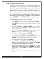
1
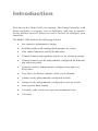
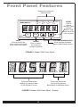
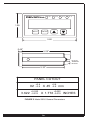
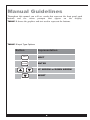
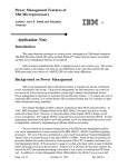
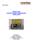
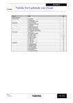
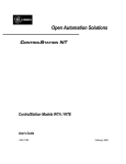
DEVAR Inc.
Model 3020
User Manual
Book 1
Introduction
Welcome to the Model 3020 user manual. This Pump Controller with
alarm capability is accurate, easy to configure, and easy to operate.
In this manual you will find an overview on how to configure your
controller.
The Model 3020 includes the following features:
Six character alphanumeric display
Scrolling multi-word configuration prompts for clarity
Four control channels with LED indication
Control channel menu prompts can be set for alarms or pumps
Control channels can be independently configured for different
trip and reset points
Controls can have independently configured trip and reset
delay times
Two, three, or all four controls can be set to alternate
Alarms can be independently configured to latch
Alarms can be independently configured to activate a horn
Four separate horn actions
A security code can be set to prevent unauthorized use
UL listed
Table of Contents
Front Panel Features . . . . . . . . . . . . . . . . ii
Manual Guidelines . . . . . . . . . . . . . . . . . . v
1.0
Basic Use - Configuration. . . . . 1
1.1
Peak and Valley . . . . . . . . . . . . . 1
1.2
Enter Access Code . . . . . . . . . . 2
1.3
Select Input Type . . . . . . . . . . . . 3
1.4
Setup Display . . . . . . . . . . . . . . . 4
1.4.1
Set the Decimal Point . . . . . . . . 4
1.4.2
Select the Process Label . . . . . . 5
1.4.3
Select the Input Output Curve . . 6
1.4.4
Define Maximum Range . . . . . . 6
1.4.5
Define Minimum Range . . . . . . . 7
1.5
Adjust Offset . . . . . . . . . . . . . . . 7
1.6
Setting Control/Alarms Points . 8
1.6.1
Trip Settings . . . . . . . . . . . . . . . . 9
1.6.2
Reset Settings . . . . . . . . . . . . . . 9
1.6.3
Trip Delay Settings. . . . . . . . . . 10
1.6.4
Reset Delay Settings . . . . . . . . 10
1.6.5
Horn Settings . . . . . . . . . . . . . . 10
1.6.6
Latch Settings . . . . . . . . . . . . . 11
1.6.7
Flash Screen Settings . . . . . . . 11
1.6.8
Fail Safe Polarity Settings . . . . 12
1.6.9
Alternation Settings . . . . . . . . . 13
1.6.10 Alarm or Pump Settings. . . . . . 13
1.7
Detecting Sensor Failure . . . . 14
1.7.1
1.7.2
1.7.3
1.8
1.9
1.10
2.0
2.1
2.2
2.2.1
2.2.2
2.2.3
2.3
2.31
2.32
3.0
4.0
5.0
A-1
NOTE: See Book 2 Configuration
Workbook
Illustrations
Figure
Figure
Figure
Figure
Figure
Figure
Figure
Figure
Figure
Figure
Relay Lock-Out Setting . . . . . . 14
Limit Settings . . . . . . . . . . . . . . 14
Relay Settings . . . . . . . . . . . . . 15
Horn Action Settings . . . . . . . . 15
Analog Retransmission. . . . . . 16
Changing the Access Code . . 17
Advanced Features . . . . . . . . . 18
DIP Switch Settings . . . . . . . . . 18
Analog Retransmission Option19
Card Configuration. . . . . . . . . . 19
Set Output Values . . . . . . . . . . 20
Adjust Output Signal . . . . . . . . 21
Non Standard Inputs . . . . . . . . 22
Square Root Response . . . . . . 22
Custom Input Curve . . . . . . . . . 23
Frequently Asked Questions . 25
Error Codes/Troubleshooting. 27
Specifications. . . . . . . . . . . . . . 28
Field Wiring . . . . . . . . . . . . . . . . 30
Warranty Information . . . . . . . . . 32
1. Front Panel.............................................. ii
2. Front Panel Display................................. ii
3. Back Panel.............................................. iii
4. Back Panel Connectors.......................... iii
5. General Dimensions ............................... iv
6. Channel Indicators on Front Panel.......... 8
7. DIP Switch................................................18
8. Analog Retransmission Log..................... 20
9. Rear Terminal Connections..................... 30
10. Field Wiring Connections...................... 31
i
Front Panel Features
Displays the status of
each channel
AL 1
DEVAR Inc.
NEXT
AL 2
AL 4
AL 3
ENTER
RESET
Click to
silence
the horn, clear
latched
alarms, and
back out of the
menu system
RESET
NEXT
Click to access the
menu system and move
to the next menu option
ENTER
Click to enter a
menu item or
accept a selection
UP/DOWN ARROW KEYS
Scroll through available
options and change values
FIGURE 1 Model 3020 Front Panel
These four characters
display the process input
or the trip point values
These two characters
are used for process
descriptors or additional zeros.
FIGURE 2 Model 3020 Front Panel - Display
ii
1.74"
3.59"
FIGURE 3 Model 3020 Back Panel
POWER: 90/140 VAC 50/60 Hz OR 130/190 VDC
ACC = AC NEUTRAL OR DC RETURN
AC = AC HOT OR ±DC ( FUSED LINE )
FUSE: 1/8A 250V LITTELFUSE SERIES 230.
INSTALLED ON PC BOARD, NOT FIELD REPLACABLE
OPTION
Vout
Isink
Isource
RS-232
RS-485
OUT_COM
COMMON
mA return
NC
COMMON
COMMON
OUT_B
Vout
+mA in
mA return
Tx
B
OUT_A
NC
NC
+mA out
Rx
A
NOTE:
Isink: EXTERNAL SUPPLY DRIVES LOOP
Isource: INTERNAL SUPPLY DRIVES LOOP
FIGURE 4 Model 3020 Back Panel - Connectors
iii
DEVAR Inc.
AL 1
AL 2
AL 3
AL 4
1.95
NEXT
ENTER
3.80
0.45"
6.05"
PLUG IN
TERMINAL
BLOCKS
5.30"
PANEL CUTOUT
92
3.622
+0.8
–0.5
+0.032
–0.019
X 45
+0.8
–0.5
mm
+0.032
X 1.772 –0.019 INCHES
FIGURE 5 Model 3020 General Dimensions
iiv
Manual Guidelines
Throughout this manual you will see words that represent the front panel push
buttons and the menu prompts that appear on the display.
TABLE 1 shows the graphics and text used to represent the buttons.
TABLE 1 Input Type Options
Button
NEXT
ENTER
Representation
NEXT
ENTER
UP ARROW or DOWN ARROW
RESET
RESET
v
Section 1
1.0 Basic Use - Configuration
This section introduces you to the basic use of the Model
3020. Before you begin to configure your controller, fill
out the pre-configuration Worksheet with the settings you
will be using (see Book 2, Page 5).
NOTE:
For ease of configuration, we recommend that you apply
power to the controller and configure it at your desk prior
to installation.
When power is first applied to the controller, the screen displays the
model number, build date, and other basic configuration parameters.
You can temporarily pause the startup message by pressing and holding
any of the buttons. After the startup message is displayed, the 3020
becomes operational and the process input is displayed. The operating
unit continuously scans the front panel switches for user input.
1.1
To enter into the menu system, press NEXT. The Peak
and Valley menu item appears.
Peak and Valley
PEAK AND VALLEY is the first menu item you will see.
This menu allows you to view and/or clear the largest and
smallest process values detected.
1.
Press ENTER. The View Peak prompt appears.
2.
Press ENTER again to view the current Peak value.
3.
After viewing the value, press NEXT. The Clear Peak
prompt appears.
1
4.
If you want to clear the Peak value, press ENTER. STOREd
is displayed confirming your selection. If you do not want to
clear the Peak value, press NEXT.
5.
The View Valley prompt appears.
6.
Press ENTER to view the current Valley value.
7.
After viewing the value, press NEXT. The Clear Valley
prompt appears.
8.
If you want to clear the Valley value, press ENTER. STOREd
is displayed confirming your selection. If you do not want to
clear the Valley value, press NEXT to return to view Peak and
Valley.
9.
Press NEXT again. The Enter Access Code prompt appears.
NOTE:
When navigating through the menu system:
1.2
Press ENTER to enter a menu item.
Press NEXT to move to the next menu item.
Press RESET to exit a menu item.
Enter Access Code
The ENTER ACCESS COdE menu item allows you to
enter the configuration menu and prevents unauthorized
modification of the meter configuration.
NOTE:
This menu item only appears if the DIP switch, SW2,
pole 4 is in the ON position. See Section 2.1, DIP
switch settings.
1.
Press ENTER. The default Access Code "000000" appears.
2.
Press the UP ARROW or DOWN ARROW to increase or
decrease the value of the flashing digit.
2
3.
Press NEXT to move to the next digit.
4.
After entering an Access Code, press ENTER. OKAY appears
if the code is correct; DENIED appears if incorrect.
1.3
Select Input Type
The SELECT INPUT TYPE menu item allows you to select the
input you want to apply to the controller.
NOTE:
You can skip this section if the input is 4/20 mA. Since
this is the factory default setting, no action is necessary.
1.
Press ENTER. The Select Input Type prompt appears.
2.
Press the UP ARROW or DOWN ARROW to view the options.
See TABLE 2 for the available options.
TABLE 2 Input Type Options
–10/+10V
0/10V
0/5V
1/5V
0/20mA
4/20mA
0/1V
3.
After selecting the Input Type, press ENTER. STORED is
displayed confirming your selection.
4.
Press NEXT. The Setup Display menu appears.
3
1.4
Setup Display
The SETUP dISPLAY menu item allows you to configure
the Model 3020 to display the level in your tank. This is
where you set the decimal point, select the process label,
and define the input/output curve.
NOTE:
The Model 3020 should be configured to match the
output range of your transmitter.
Press ENTER. The SET dP prompt appears.
1.4.1 Set the Decimal Point
The SET dP prompt allows you to place the decimal point.
1.
Press ENTER. The current setting appears as a flashing digit
with the decimal point to the right of the digit (factory setting:
012.345).
2.
Press the UP ARROW or DOWN ARROW to move the decimal point to the desired position.
3.
After positioning the decimal point, press ENTER. STOREd
is displayed confirming your selection.
NOTE:
Only the first four digits, ‘0123’, will actively display the
input regardless of where the decimal point is placed.
When either ‘01234.5’ or ‘012345.’ is selected as a
decimal point position, dummy zeros will occupy the
‘45’ positions that would otherwise be used to display the
label.
4
1.4.2 Select the Process Label
The PICK LABEL prompt allows you to set the two character process
label.
1.
Press ENTER. The current setting appears with a flashing character.
NOTE:
In this example, XX is the current setting. The flashing
character is the character you can edit. A blank space
is also a valid character.
2.
Press the UP ARROW or DOWN ARROW to find the desired
character.
NOTE:
Characters include numbers 0 through 9, upper and lower
case letters, and other characters as @, #, etc., or blank.
3.
To edit the next character, press NEXT.
4.
Press the UP ARROW or DOWN ARROW to find the desired
character.
5.
Press ENTER to save the setting. STOREd is displayed confirming your selection.
5
1.4.3 Select the Input Output Curve
The INPUT OUTPUT CURVE prompt allows you to configure the
display for a linear or nonlinear input curve. This prompt defines how
the unit reacts to the input signal.
1.
Press ENTER. The current setting appears.
NOTE:
The factory default setting is LINEAR INPUT. For more
information about other settings, see Section 2.3,
Sections 1.4.4 and 1.4.5 are only for LINEAR INPUT.
2.
Press the UP ARROW or DOWN ARROW to change the current
setting.
3.
Press ENTER to save the setting. STOREd is displayed confirming your selection.
1.4.4 Define Maximum Range
The dEFINE MAX. RANGE prompt allows you to set the
process value to be displayed at the maximum input signal.
1.
Press ENTER. The current setting appears.
2.
Press the UP ARROW or DOWN ARROW to increase or decrease
the value of the flashing digit.
3.
Press NEXT to move to the next digit.
4.
After changing all the digits, press ENTER to save the setting.
STOREd is displayed confirming your selection.
6
1.4.5 Define Minimum Range
The dEFINE MIN. RANGE prompt allows you to set the process
value to be displayed at the minimum input signal.
1.5
1.
Press ENTER. The current setting appears.
2.
Press the UP ARROW or DOWN ARROW to increase or
decrease the value of the flashing digit.
3.
Press NEXT to move to the next digit.
4.
After changing all the digits, press ENTER to save the setting.
STOREd is displayed confirming your selection.
Adjust Offset
The AdJUST OFFSET menu item allows you to add or subtract a
value from the display to accommodate the location of the transmitter.
For example, if the transmitter is on the bottom of the tank, the setting
is zero; if the transmitter is 1 ft. off the bottom, the setting is one.
1.
Press ENTER. The current setting appears.
2.
Press the UP ARROW or DOWN ARROW to increase or
decrease the value of the flashing digit.
3.
Press NEXT to move to the next digit.
4.
After changing all the digits, press ENTER to save the setting.
STOREd is displayed confirming your selection.
5.
Press NEXT.
7
1.6
Setting Control or Alarms Points
The Model 3020 has four control or alarm channels. LEDs on the
front panel indicate which channel(s) has been tripped. See FIGURE
6 for an example of channels tripped on two pumps.
Indicates channels have
been tripped on two pumps
AL 1
DEVAR Inc.
NEXT
AL 2
AL 3
AL 4
ENTER
RESET
FIGURE 6 Channel indicators on the front panel
1.
The PUMP 1 or ALARM 1 prompt appears. Press ENTER to
configure the channel.
2.
Or press NEXT to move to the next channel.
NOTE:
Each of the channels may be set to display “PUMP” or
“ALARM”. Each setting has the channel number as part
of the prompt.
8
1.6.1 Trip Settings
The TRIP prompt allows you to set the point at which the pump turns
on or the alarm trips.
1.
The TRIP 1 prompt appears.
2.
Press ENTER. The current setting appears.
3.
Press the UP ARROW or DOWN ARROW to increase or
decrease the value of the flashing digit.
4.
Press NEXT to move to the next digit.
5.
After changing all the digits, press ENTER to save the setting.
STOREd is displayed confirming your selection.
1.6.2 Reset Settings
The RESET prompt allows you to set the point at which the pump turns
off or the alarm resets.
NOTE:
1. If you set the TRIP point to a higher value than the
RESET point, the alarm is configured as a high alarm
if you set the trip point to a lower value than the
RESET point, it is configured as a low alarm.
2. Setting the TRIP and RESET points to the same value
disables the channel and de-energizes the relay.
1.
The RESET 1 prompt appears.
2.
Press ENTER. The current setting appears.
3.
Press the UP ARROW or DOWN ARROW to increase or
decrease the value of the flashing digit.
4.
Press NEXT to move to the next digit.
5.
After changing all the digits, press ENTER to save the setting.
STOREd is displayed confirming your selection.
9
1.6.3 Trip Delay Settings
The TRIP dELAY prompt controls the length of time the process
must remain beyond the TRIP value before activating the
alarm/control. Delay times can be set from 0 to 240 seconds.
1.
The TRIP dELAY 1 prompt appears. Press ENTER. The current
setting appears.
2.
Press the UP ARROW or DOWN ARROW to increase or
decrease the value of the flashing digit.
3.
Press NEXT to move to the next digit.
4.
After changing all the digits, press ENTER to save the setting.
STOREd is displayed confirming your selection.
1.6.4 Reset Delay Settings
The RESET dELAY prompt controls the length of time the
process must remain beyond the RESET value before de-activating the alarm/control. Delay times can be set from 0 to 240 seconds.
1.
The RESET dELAY 1 prompt appears. Press ENTER. The current setting appears.
2.
Press the UP ARROW or DOWN ARROW to increase or
decrease the value of the flashing digit.
3.
Press NEXT to move to the next digit.
4.
After changing all the digits, press ENTER to save the setting.
STOREd is displayed confirming your selection.
1.6.5 Horn Settings
The HORN prompt allows you to set each alarm to activate a horn.
1.
The HORN 1 prompt appears. Press ENTER. The current setting appears.
2.
Press the UP ARROW or DOWN ARROW to select SILENT
or SOUNd.
3.
Press ENTER to save the setting. STOREd is displayed confirming your selection.
10
1.6.6 Latch Settings
The LATCH prompt allows you to configure a channel to remain
latched in the alarm state even after the input has returned to a nonalarm condition.
1.
The LATCH 1 prompt appears. Press ENTER. The current setting appears.
2.
Press the UP ARROW or DOWN ARROW to select dO NOT
LATCH or dOES LATCH.
3.
Press ENTER to save the setting. STOREd is displayed confirming your selection.
NOTE:
A latched alarm can be cleared by pressing the R E S E T
button on the front panel (see FIGURE 1).
1.6.7 Flash Screen Settings
The FLASH SCREEN prompt allows you to configure the controller
to indicate a tripped condition by flashing the display.
1.
The FLASH SCREEN prompt appears. Press ENTER. The current setting appears.
2.
Press the UP ARROW or DOWN ARROW to select ON
ALARM or NEVER.
3.
Press ENTER to save the setting. STOREd is displayed confirming your selection.
11
1.6.8 Fail Safe Polarity Settings
The FAIL SAFE POLARITY prompt allows you to select whether
the output relay will be energized, (N.O. contact closed) or de-energized, (N.C. contact closed) when in the tripped state.
NOTE:
For FAIL TRIPPED, the channel will trip on the loss of
power.
For FAIL RESET, the channel will reset on the loss of
power.
1.
The FAIL SAFE POLARITY 1 prompt appears. Press ENTER.
The current setting appears.
2.
Press the UP ARROW or DOWN ARROW to select
FAIL RESETor FAIL TRIPPd.
3.
Press ENTER to save the setting. STOREd is displayed confirming your selection.
TIP:
After installing the controller, perform a safety test by removing
power to the 3020. The relays are wired correctly If the controlled functions are all in their failsafe conditions, (e.g., the
pumps are off and the alarms are on).
12
1.6.9 Alternation Settings
The ALTERNATION prompt allows you to set any of two, three or
four channels to alternate. Each channel is configured separately. Each
time the first trip point is reached, one of the alternating channels will
turn a pump on. Another pump will turn on for each additional trip point
that is reached.
NOTE:
Alternating channels must be set so that they all trip on
a high going signal or all trip on a low going signal. The
trip points should all be set to different values.
1.
The ALTERNATION prompt appears. Press ENTER. The current setting appears.
2.
Press the UP ARROW or DOWN ARROW to select dO NOT
TOGGLE or dOES TOGGLE.
3.
Press ENTER to save the setting. STOREd is displayed confirming your selection.
1.6.10 Alarm or Pump Settings
The ALARM or PUMP prompt allows you to label the channel that
you are configuring as an alarm or as a pump control.
1.
The ALARM OR PUMP prompt appears. Press ENTER. The
current setting appears.
2.
Press the UP ARROW or DOWN ARROW to select PUMP or
ALARM.
3.
Press ENTER to save the setting. STOREd is displayed confirming your selection.
NOTE:
To configure channels 2 through 4, repeat the steps in
the Alarm Settings Sections 1.6. to 1.6.10
13
1.7
Detecting Sensor Failure
The DETECT SENSOR FAILUR menu item gives you the option
to control the relay outputs if the sensor fails.
1.
The DETECT SENSOR FAILUR prompt appears.
2.
Press ENTER to enter the RELAY LOCK-OUT menu.
3.
Or press NEXT to move to HORN ACTION.
1.7.1 Relay Lock-Out Setting
The RELAY LOCK-OUT prompt allows you to define the input
values that indicate a faulty sensor and the state each relay will enter
if the sensor fails.
1.
The RELAY LOCK-OUT prompt appears. Press ENTER. The
current setting appears.
2.
Press the UP ARROW or DOWN ARROW to select ENABLE
or IGNORE.
3.
Press ENTER to save the setting. STOREd is displayed confirming your selection.
1.7.2 Limit Settings
The LIMIT1 and LIMIT2 prompts allow you to specify the maximum and minimum input values that define a valid signal range.
1.
The LIMIT1 prompt appears. Press ENTER. The current setting
appears.
2.
Press the UP ARROW or DOWN ARROW to increase or
decrease the value of the flashing digit.
3.
Press NEXT to move to the next digit.
4.
After changing all the digits, press ENTER to save the setting.
STOREd is displayed confirming your selection.
5.
Press NEXT. Repeat the process for LIMIT 2.
14
NOTE:
LIMIT 1 and LIMIT 2 define the limits of a valid input
range. Limits are specified in terms of the displayed
process value not the electrical signal, e.g. 11.5 ft. not
20 mA. It does not matter which LIMIT is used to
represent the top or the bottom of the range.
1.7.3 Relay Settings
The RELAY1 through RELAY4 prompts allow you to specify the state
each relay will be placed in after an input failure is detected.
1.8
1.
The RELAY1 prompt appears. Press ENTER. The current setting appears.
2.
Press the UP ARROW or DOWN ARROW to select TRIPPd or
RESET.
3.
Press ENTER to save the setting. STOREd is displayed confirming your selection.
4.
Press NEXT. Repeat the process for the next relay.
Horn Action Settings
The horn will be enabled if DIP switch SW2 pole 3 is set to ON (see
section 2.1). The HORN ACTION menu item allows you to control
how the horn reacts (i.e., what triggers it to sound and what causes it to
go silent). Any, none, or all of the alarms can cause the horn to sound.
NOTE:
The R E S E T button on the front panel (see FIGURE 1)
is used to silence the horn. If the alarm is latched,
pressing R E S E T a second time will unlatch the alarm.
15
1.
The HORN ACTION prompt appears. Press ENTER. The current setting appears.
2.
Press the UP ARROW or DOWN ARROW to select SOUNd
WITH ALARM, SOUNd UNTIL RESET, LATCH GOING ACTIVE
or LATCH WITH CHANGE (see table 3).
3.
Press ENTER to save the setting. STOREd is displayed confirming your selection.
TABLE 3 Horn Actions
Setting
Description
SOUNd WITH ALARM
Causes the horn to sound when an alarm
is tripped and to be silent when all alarms
are clear. If any alarm is configured to
LATCH, you must press RESET to unlatch
alarms that are clear.
SOUNd UNTIL RESET
The horn sounds when an alarm is
tripped and is silent when either all
alarms are clear or the RESET is
pressed. If any alarm is configured to
LATCH, you must press RESET again to
unlatch alarms that are clear.
LATCH GOING ACTIVE The horn sounds and stays on after an
alarm is tripped. You can only silence the
horn by pressing the RESET button. If
any alarm is configured to LATCH, you
must press RESET again to unlatch
alarms that are clear.
LATCH WITH CHANGE The horn sounds and stays on after an
alarm either trips or clears. You can only
silence the horn by pressing the RESET
button. If any alarm is configured to
LATCH, you must press RESET again to
unlatch alarms that are clear.
1.9
Analog Retransmission
The ANALOg REXMIT menu item allows you to configure the
analog output option. This prompt only appears if the Analog
Retransmission Option has been provided. For a complete description of the option, see Section 2.2.
16
1.10 Changing the Access Code
The CHANGE ACCESS COdE menu item allows you to define a
new access code.
1.
The CHANGE ACCESS CODE prompt appears. Press ENTER.
The current Access Code appears.
2.
Press the UP ARROW or DOWN ARROW to increase or
decrease the value of the flashing digit.
3.
Press NEXT to move to the next digit.
4.
After entering the Access Code, press ENTER. STOREd is displayed confirming your selection.
5.
Press NEXT to return to the top of the menu system or press
RESET to exit the menu system.
TIP:
If you forget the Access Code, set the DIP switch SW2 pole
4 to the OFF position to disable the access code (lockout). A
new Access Code can be entered as described above.
Lockout can be reactivated by turning switch 4 back on.
17
Section 2
2.0 Advanced Features
2.1
DIP Switch Settings
DIP switches are located on the bottom of the controller. Various functions are controlled by these switches. See TABLE 4 for the function
for each switch position. See FIGURE 7 for a picture of the DIP Switch.
TABLE 4 DIP Switch Settings
Pole Position
Function
Description
Pole 1
Analog
Retransmission
Calibration
Set switch to ON position to
calibrate retransmission board,
see. Adjust Output Signal
Section 2.2.3
Pole 2
System
Initialization
and Calibration
This switch position should
always be in the OFF position.
Pole 3
Audible Alarm
When set to the ON position, the
horn is enabled to sound.
Pole 4
Setup
Protection
When set to the ON position, the
controller checks the access
code to verify the user can
access the menu system.
NOTE: Contact the factory for
further information.
SW4
1
2
3
4
O
N
FIGURE 7 DIP SWITCH
18
2.2
Analog Retransmission Option
The Analog Retransmission Option provides an analog output proportional to the process variable being displayed by the controller (e.g., the
level in the tank). The retransmitted output signal does not have to be the
same as the input signal. For example, the controller could accept a 4 to 20
mA input and provide a 0 to 10 volt output. The retransmitted signal is
scaled with respect to the displayed process value. Any linearization applied
to the input is incorporated into the retransmitted signal. The two process
values that define the end points of the retransmitted signal are set using the
menu system. This allows the input and retransmitted signals to have different ranges (i.e., a 4 to 20 mA input could represent a level of 0 to 23.1 ft.
with the retransmission scaled to output 4 mA at 1 ft. and 20 mA at 21 ft.).
To access the menu to configure analog retransmission:
1. Press NEXT repeatedly to navigate to ANALOG REXMIT.
2. Press ENTER.
NOTE:
The resolution of the output signal is only as good as
the resolution of the display and will never be better
than 0.05% of the output span.
2.2.1 Card Configuration
The DIP switches on the retransmission card are used for setting the output range of the Card. The final calibration is done through the menu
system, see sections 2.2.2 and 2.2.3. To access the analog retransmission
card, unplug the two rear terminal blocks and remove the back plate. Set
the DIP Switches to configure the card for a maximum output of 5V,
10V, or 20mA. See FIGURE 8 and TABLE 5 for DIP Switch settings.
NOTE:
The retransmitted signal does not have to be the same
type of signal as the input (e.g., a 0/10 V input can be
retransmitted as a 4/20 mA signal).
19
J7
J8
DEVAR INC.
ANALOG OUTPUT
516127-0001 REV B
OUTPUT
5V
10V
20mA
ON
1,2
2
3,4
SW4
OFF
3,4
1,3,4
1,2
1
2
3
4
O
N
Q2
1
2
3
4
O
N
5V
1
2
3
4
O
N
10V
1
2
3
4
O
N
20mA
FIGURE 8 Analog Retransmission Card
TABLE 5 Output Settings
Output
ON
OFF
5V
1, 2
3, 4
10V
2
1, 3, 4
20mA
3, 4
1, 2
2.2.2 Set Output Values
The user must define the process value that appears on the display to produce the minimum retransmitted output (e.g., 4 mA.)
and the process value that produces the maximum retransmitted
output,e.g. 20 mA.
1.
Navigate to the ANALOG REXMIT prompt and press ENTER.
2.
The dISPLY@MIN OUTPUT prompt appears
3.
Press ENTER. The current setting appears.
4.
Press the UP ARROW or DOWN ARROW to increase or
decrease the value of the flashing digit.
5.
Press NEXT to move to the next digit.
6.
After changing all the digits, press ENTER to save the setting.
STOREd is displayed confirming your selection.
7.
The dISPLY@MAX OUTPUT prompt appears Repeat steps 3
through 6 for the dISPLAY@ MAX OUTPUT menu item.
NOTE:
The default factory calibration for analog retransmission
is a 4 to 20 mA output for a 0 to 100% input.
20
2.2.3 Adjust Output Signal
The analog retransmission board is calibrated using the TRIM MIN
OUTPUT and TRIM MAX OUTPUT menu items. This is a factory
calibration and does not have to be performed on new units unless the
DIP switch settings are being changed on the retransmission card. The
output of the analog retransmission board is controlled by sending it a
number. The number can range from 0 to 4095; the larger the number,
the larger the output. Calibration consists of adjusting the number up or
down to increase or decrease the measured output level.
NOTE:
The TRIM MIN OUTPUT and TRIM MAX OUTPUT
menu prompts only appear when DIP switch, SW4,
Pole 1 is in the ON position (see Section 2.1).
To adjust the output signal:
1.
Connect an appropriate meter (voltage or milliamp) to the analog output terminals on the rear panel.
2.
Navigate to the ANALOG REXMIT prompt then press ENTER.
3.
Press NEXT Until the TRIM MIN OUTPUT prompt appears
then press ENTER.
4.
The number controlling the output signal for this calibration
point is displayed.
5.
Press the UP ARROW or DOWN ARROW to increase or
decrease the value of the flashing digit.
6.
Changing the value of the displayed number will cause a decimal point to appear. When the decimal point is present, the
number is in the edit mode and is no longer controlling the output. Pressing NEXT or ENTER will update the analog output
and remove the decimal point.
21
7.
With the decimal point removed pressing NEXT moves to the
next digit to edit. Changing the number will cause the decimal
point to reappear. Pressing NEXT or ENTER will once again
update the analog output and remove the decimal point.
8.
Repeat steps 5 through 7 until the analog output reaches the
proper value.
9.
Press ENTER, STOREd is displayed confirming your selection.
10. The TRIM MAX OUTPUT prompt appears.
11. Repeat steps 4 through 9 for the TRIM MAX OUTPUT menu item.
2.3
Non Standard Inputs
A standard input is any input in which the displayed process
varies linearly with the input signal. A linear curve is defined by
its two end points as described in sections 1.4.4 and 1.4.5. All
other inputs are nonstandard.
2.31 Square Root Response
A square root response is a nonlinear curve in which the displayed
process varies as the square root of the input signal. The user must
specify the top of the range. The starting point is always zero, (e.g.,
4 to 20 mA represents 0 to 2000 gpm).
1.
Follow the display setup procedure, sections 1.4 through 1.4.3.
2
At the INPUT OUTPUT CURVE prompt, Press ENTER. The
current setting appears.
3
Press the UP ARROW or DOWN ARROW to select SQUARE
ROOT.
4
Press ENTER, DEFINE MAX RANGE appears
5.
Press ENTER, The current setting appears.
6.
Press the UP ARROW or DOWN ARROW to increase or
decrease the value of the flashing digit.
7.
Press NEXT to move to the next digit.
8.
After changing all the digits, press ENTER to save the setting.
STOREd is displayed confirming your selection.
22
2.32 Custom Input Curve
The custom curve function allows you to approximate a nonlinear, signal to process curve, by using up to 16 straight-line segments. The
straight-line segments are defined by entering a series of break points,
labeled from "BP 0" to "BP 16." When entering break points, first
define at what percentage of the input the break point falls, then define
the desired process value at that break point. Breakpoints can be located between 0% and 100% of the input range. Breakpoints that are located at percentages above 100% will be removed from the list of active
breakpoints. If there are less than 17 breakpoints, more can be added by
pressing ENTER at the ADD BREAKPOINT prompt. Breakpoints can
be edited or added in any order. The program will sort the breakpoints
into an ascending order after the entry is completed.
1.
Press NEXT until SETUP DISPLAY appears, press ENTER.
2.
Press NEXT until INPUT OUTPUT CURVE appears. Press
ENTER.
3.
Press UP ARROW or DOWN ARROW until CUSTOM
CURVE appears. Press ENTER. STOREd is displayed confirming your selection.
4.
To set a breakpoint, press ENTER at the BP(n) prompt, or press
NEXT to move on to the next break point, BP(n+1).
5.
At INPUT % at BP(n) prompt, press ENTER.
6.
Press NEXT and UP ARROW or DOWN ARROW to set the
location of BP(n) between 00.00% and 100.00%. Press
ENTER. OKAY is displayed confirming your selection.
7.
At the dISPLAY at BP(n) prompt, press ENTER.
8.
Press NEXT and UP ARROW or DOWN ARROW to set the
display to the desired process value at BP(n). Press ENTER.
STOREd is displayed confirming your selection.
9.
If you have defined fewer than 17 breakpoints, the ADD
BREAKPOINT prompt appears. Press ENTER to add another
break point or press NEXT to return to the SETUP
dISPLAY.prompt.
10. Repeat steps 4 through 9 until all the break points have been
defined.
23
NOTE:
1. No two brealpoints can have the same input percentage but
they can have the same output value.
2. There cannot be less than 2 or more than 17 breakpoints.
3. Use the N E X T key to skip over breakpoints that do not need
to be changed.
4. To delete breakpoints that have already been added, set the
process value above 100% at the INPUT % at BP(n) prompt.
5. Use the R E S E T key to exit the custom curve configuration
and return to the SETUP dISPLAY prompt.
24
Section 3
3.0 Frequently Asked
Questions
Question:
Answer:
If my tank is 10 feet deep
should I set my "define
maximum range" to 10
feet?
No. The "define maximum range" and
the "define minimum range" should
be set to match the output of the signal transmitter. For example, if you
are using a 5 lb pressure transducer,
set the minimum to 0 ft and the maximum to 11.5 ft.
What do I do if the pressure transducer is not
located at the bottom of
the tank?
Calibrate the controller to match the
range of the transducer (e.g. 0 to 11.5
ft.), then use the "adjust offset" feature to correct for the position of the
transducer.
How do I indicate the
depth of water in my well,
if the transmitter output is
reverse acting, (the output goes down as the
well fills up)?
An ultrasonic transmitter might output 4
mA at a distance of 25 ft and 20 mA at
a distance of 1.5 ft. Set the "define
maximum range" to 1.50 ft and the
"define minimum range" to 25.00 ft.
then use the "adjust offset" feature to
compensate for the height of the
Transmitter above the well.
If I have two alternating
pumps should the trip
and reset points for
both pumps be set to
the same level?
No. This will cause both pumps to
turn on at the same time. One pump
must be set to turn on at a higher
level than the other. The pumps will
alternate around the first trip point. If
the second trip point reached, both
pumps will turn on. The reset points
can be set to the same value.
The controller seems to
operate properly regardless of how the "failsafe
polarity" is set. Is this an
important setting?
Yes. This setting determines what
happens if there is a loss of power to
the controller. Setting the failsafe to
"fail reset" for a pump control will turn
the pump off on power loss. Setting
the failsafe to "fail tripped" for an
alarm will activate the alarm on
power loss.
25
Frequently Asked
Questions (cont.)
Question:
Answer:
Why are the pumps being
turned on when the controller is not in the tripped
state?
The relay contacts may be wired
incorrectly. Relay action is affected
by the "failsafe polarity" setting.
For "fail tripped," the pole and NC
contact are closed in the tripped
state. For "fail reset," the pole and
NO contact are closed in the
tripped state.
I have a nonlinear response
programmed into the controller, Can I compensate for a
change in the position of the
pressure transducer by using
the "adjust Offset" function?
No. You must generate a new custom curve, linearization table,
defining the relationship between
the level and the shifted transducer output.
How can I save time while
navigating through the
menu system?
Repeatedly press the NEXT button
to skip past menu items that do not
need to be changed. Use the
RESET button to jump from a submenu prompt back to the main
menu. Use the RESET button to
jump from the main menu back to
displaying the measured process.
Why did my analog
retransmission stop working properly after the controller was reconfigured
for a different tank level?
The analog output is not a function of
the input signal (e.g., 4 to 20 mA) but
is defined by the tank levels which
appear on the display. If the display
configuration is changed, the analog
retransmission will have to be reconfigured.
26
Section 4
4.0 Error Codes/
Troubleshooting
Error:
Description:
+ OVER
Appears when trying to display a value outside of
the numeric range of the meter, i.e., greater than
9999. If this message appears, verify that the
input signal is valid, that the input is wired correctly and that the input defined at "Select Input Type"
matches the signal being applied to the controller.
- OVER
Appears when trying to display a value outside of
the numeric range of the meter, i.e., less than
-1999. If this message appears, verify that the
input signal is valid, that the input is wired correctly and that the input defined at "Select Input Type"
matches the signal being applied to the controller.
No A/D
The analog to digital converter is not communicating with the microcontroller. If this message
appears, try cycling power to the unit. If this does
not solve the problem, the unit has been damaged and should be returned for repair.
EEPROMERROR
The microcontroller is receiving invalid data
from the EEPROM. If this message appears,
try cycling power to the unit. If this does not
solve the problem, the unit has been damaged
and should be returned for repair.
DUPLICATE ENTRY
When configuring a custom input curve, this
message will appear if you attempt to define
two breakpoints at the same input percentage.
NOT ENOUGH VALID
BREAK POINTS
When configuring a custom input curve, this message will appear if only one break point has been
defined. A custom curve can have any number of
breakpoints between 2 and 17.
DENIED
This message appears if you have entered an
invalid access code when trying to enter the
menu system. If you have forgotten the access
code, refer to Section 1.2 of this manual.
27
Section 5
5.0 Specifications
Power Requirement
90-140VAC Single Phase 50/60Hz or 130-190VDC,
10 VA max
Operating Temperature
0ºC to 70ºC
Dimensions
Front Bezel
Panel Cutout
Overall
48mm H x 96mm W x 12mm
45mm H x 91mm W
48mm H x 96mm W x 166mm D
Environmental Rating
Type 1, Splash resistant front panel
Weight
0.522Kg = 1.15lbs. = 18.4oz
Display
Six characters, 0.54" high, 15 segment, Alpha-Numeric,
high efficiency red LED
User Input
Four button integrated membrane switch front panel keypad
Output Relay
SPDT (form C) relays; 1 Phase; 7.5A at 240VAC/24VDC;
1/3 HP at 120VAC (7.2 FLA); ½ HP at 240VAC (4.9 FLA)
Max Terminal
Screw Torque
7 lb./in.
Relay Operation
1) Relay de-energizes on power failure, which causes closure
between P and NC. An energized relay has closure between P
and NO.
2) A failsafe polarity of FAIL TRIPPED de-energizes the
relay in the alarm (tripped) condition, the LED is lit. A failsafe polarity of FAIL RESET de-energizes the relay in the
non-alarm (reset) condition, the LED is dark.
3) When enabled, detected sensor failure will cause all
relays to go to the selected states, either tripped or reset.
Loop Power Supply
Isolation Strength
24V @ 100mA MAX, 150mA short circuit
500VAC to input terminals or earth
INPUT
A/D converter
24 bit Delta-Sigma type
Reference
2.5V ±15ppm / ºC typical
Voltage Input Impedance 1M Ohms
Current Input Impedance 10 Ohms
28
5.0 Specifications (cont.)
-3dB frequency
12Hz.
Acceptable inputs
± 10V, 0/10V, 0/5V, 1/5V, 0/20mA, 4/20mA, 0/1 V
Display update rate
2 Hz
Accuracy
± 0.01% of span ± 1 count
INDICATION
Displayable numeric range
-1999 to 9999 with decimal point to right of any
digit
Scaling linear response
Define process values at minimum and maximum
signal input
Scaling square root response
Define process value at maximum signal input
Linearization error:
Scaling custom curve
< 0.5% for input below 1% of full scale, < 0.001%
otherwise
User defines 2 to 17 values at a percentage of input
level.
OPTIONAL ANALOG
RETRANSMISSION
D/A converter
12 bits
Available full scale outputs
5V, 10V, 20mA
Accuracy relative to display
<0.05% of full scale output, see secection 2.2
AGENCY APPROVALS
51 JB
INDUSTRIAL CONTROL EQUIPMENT
29
Appendix
A.1
Field Wiring
RELAYS
POWER
AL 1
NC
AL 2
NC
NO
AL 3
P
AL 4
NC
NO
P
GND
P
NO
NO
P
NC
NO
P
NC
AC
ACC
1
2
3
4
5
6
7
8
9
+24V
24V return
(-)VIN
(+)VIN
(-)mA IN
(+)mA IN
OUT_A
OUT_B
OUT_COM
POWER: 90/140 VAC 50/60 Hz OR 130/190 VDC
ACC = AC NEUTRAL OR DC RETURN
AC = AC HOT OR ±DC ( FUSED LINE )
FIGURE 9 Rear Terminal Connections
30
4/20mA INPUT
2-WIRE TRANSMITTER
EXTERNAL SUPPLY
OUT_COM
ADD
4/20mA INPUT
2-WIRE TRANSMITTER
INTERNAL SUPPLY
OUT_COM
JUMPER
+mA TO +Vin
OUT_B
ADD
JUMPER
+mA TO +Vin
OUT_B
OUT_A
OUT_A
(+)mA IN
(+)mA IN
-PS
(-)mA IN
(+)VIN
-PS
(-)mA IN
TRANSMITTER
TRANSMITTER
(+)VIN
+PS
(-)VIN
+PS
(-)VIN
24V return
+24V
+V
POWER
24V return
-V
SUPPLY
+24V
4/20mA INPUT
4-WIRE TRANSMITTER
EXTERNAL SUPPLY
VOLTAGE INPUT
4-WIRE TRANSMITTER
EXTERNAL SUPPLY
OUT_COM
OUT_COM
OUT_B
OUT_B
OUT_A
OUT_A
+PS
(+)mA IN
+OUT
(-)mA IN
-OUT
+PS
(+)mA IN
+OUT
(-)mA IN
-OUT
TRANSMITTER
-PS
(+)VIN
(-)VIN
ADD JUMPER
+mA TO +Vin
24V return
24V return
+24V
+24V
VOLTAGE INPUT
3-WIRE TRANSMITTER
EXTERNAL SUPPLY
OUT_COM
VOLTAGE INPUT
3-WIRE TRANSMITTER
INTERNAL SUPPLY
OUT_COM
TRANSMITTER
OUT_B
+OUT
OUT_A
-PS
OUT_A
(+)mA IN
OUT_B
+PS
(+)mA IN
(-)mA IN
(-)mA IN
(+)VIN
+V
POWER
(+)VIN
(-)VIN
-V
SUPPLY
(-)VIN
24V return
24V return
+24V
+24V
OUT_COM
OUT_A
OUT_COM
– OUT
TRANSMITTER
SIGNAL
-PS
+PS
4/20 mA OUTPUT
EXTERNAL SUPPLY
4/20 mA OUTPUT
OUT_B
-PS
(+)VIN
(-)VIN
COM
-V
POWER
SUPPLY
+V
OUT_B
– LOAD +
+ OUT
OUT_A
(+)mA IN
(+)mA IN
(-)mA IN
(-)mA IN
I SINK
(+)VIN
– LOAD +
(+)VIN
(-)VIN
(-)VIN
24V return
24V return
+24V
+24V
VOLTAGE OUTPUT
OUT_COM
COM
+ OUT
OUT_B
OUT_A
(+)mA IN
+ LOAD –
FIGURE 10 Field Wiring Connections
(-)mA IN
(+)VIN
(-)VIN
24V return
+24V
31
Warranty Information
DEVAR INC. WARRANTS THIS PRODUCT AGAINST FAILURE
AS A RESULT OF DEFECTS IN MATERIAL OR WORKMANSHIP
FOR A PERIOD OF TWO YEARS. Should this product prove to be
defective in material or workmanship during the warranty period, Devar
Inc. will, at its discretion, repair or replace the defective item at no
charge to the customer. Products that are damaged by accident, misuse,
fire, water, lightning or other acts of nature are not covered under this
warranty. Also not covered, is damage, due to shipping, installation,
incorrect wiring or any other cause not related to a product defect.
Unauthorized product modification, repair or attempted repair, or serial
number modification will void the warranty.
32
DEVAR Inc.
706 Bostwick Ave
Bridgeport CT 06605 U.S.A.
800 566 6822, www.devarinc.com
MODEL 3020 Rev.D