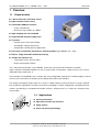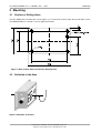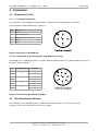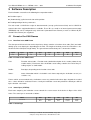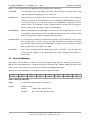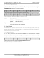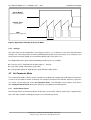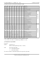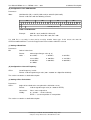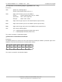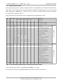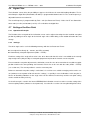
1
360° Inclination Sensors Figure similarly with CAN Bus Interface User Manual MR405.1111.1 (D) MR405.1121.1 Version: 2.2 Date: August 25th 2006 User Manual MR405.1111.1 / MR405.1121.1 - 360° Revision History Revision History Date Revision Changes 2004-03-25 0 - First version 2004-04-27 1 - Extension of the CAN protocol 2004-04-30 2 - Various changes 2004-09-01 3 - Correction of mistake in ordering information 2004-10-08 4 - Various changes and correction of mistakes 2005-06-06 5 - Various changes 2005-09-28 0 - Adaptation of technical data to new sensor - documentation of functional enhancement (digital filter) 2006-03-02 1 - Correction of layout 2006-08-25 2 - Correction of ordering information, technical data extended Version 2 © Copyright 2006 Micronor AG This document is subject to change without notice. We constantly work to further develop of our products. We reserve any changes of the scope of delivery in shape, equipment and technology for ourselves. No claims can be made from the details, illustrations and descriptions in this documents. Any kind of duplication, reprocessing and translation of this document as well as excerpts from it require the written permission of Micronor AG. All rights according to the copyright remain explicitly reserved for Micronor AG Preliminary User Manual · Document: MR405 · Page: 2/21 Subject to change without notice · © 2006 Micronor AG User Manual MR405.1111.1 / MR405.1121.1 - 360° Table of Contents Table of Contents 1 Overview.........................................................................................................................................................5 1.1 Characteristics..........................................................................................................................................5 1.2 Applications..............................................................................................................................................5 2 Technical Data................................................................................................................................................6 3 Mounting.........................................................................................................................................................7 3.1 Position of Drilling Holes..........................................................................................................................7 3.2 Definition of the Axes...............................................................................................................................7 4 Connection......................................................................................................................................................8 4.1 Connector Pin Out....................................................................................................................................8 4.1.1 4.1.1 CAN Bus Connection..............................................................................................................8 4.1.2 4.1.2 Connection of Switching Output (Type MR405.1121.1) .........................................................8 4.2 Bus-Termination Resistor........................................................................................................................8 5 Software Description.....................................................................................................................................9 5.1 Format of the CAN Frames......................................................................................................................9 5.1.1 Data Part in the CAN Frame............................................................................................................9 5.1.2 Status Byte (STATUS).....................................................................................................................9 5.2 Boot Up Message...................................................................................................................................10 5.3 Position Request Mode..........................................................................................................................11 5.4 Cyclic Mode............................................................................................................................................11 5.4.1 Operation Procedure......................................................................................................................11 5.4.2 Settings..........................................................................................................................................12 5.5 Set Parameter Mode..............................................................................................................................12 5.5.1 Set Parameter Frame....................................................................................................................12 5.5.2 Reply Parameter Frames...............................................................................................................16 5.6 Digital Filter.............................................................................................................................................17 5.7 Setting of the Zero Point.........................................................................................................................17 5.7.1 Operational Principle......................................................................................................................17 5.7.2 Settings..........................................................................................................................................17 5.8 Use of the Switching Outputs (Type MR405.1121.1).................................................. ..........................18 5.8.1 5.8.1 Operational Principle.............................................................................................................18 5.8.2 Settings..........................................................................................................................................18 5.9 Status Display of the Two-Coloured LED...............................................................................................19 5.10 Default Device Parameters..................................................................................................................20 6 Ordering Information...................................................................................................................................21 Preliminary User Manual · Document: MR405 · Page: 3/21 Subject to change without notice · © 2006 Micronor AG User Manual MR405.1111.1 / MR405.1121.1 - 360° List of Tables List of Tables Table 1: Technical Data .................................................................................................................................... 6 Table 2: Format of the CAN Frames ................................................................................................................. 9 Table 3: Status Byte .......................................................................................................................................... 9 Table 4: “Boot Up” Message ........................................................................................................................... 10 Table 5: Request frame: Request Position Update ID (default ID = 100h) ..................................................... 11 Table 6: Reply frame: Reply Position Update ID (default ID = 101h) .............................................................. 11 Table 7: Cyclic position frame: Cyclic Position Update ID (default ID = 201h) ............................................... 11 Table 8: Supported FSC and Parameters of the Set Parameter Frames ....................................................... 13 Table 9: CAN Identifier .................................................................................................................................. 14 Table 10: Restoration of Default Device Parameters ...................................................................................... 15 Table 11: Function Codes and Parameters of the Reply Parameter Frames ................................................. 16 Table 12: Default Settings of the Device Parameters ..................................................................................... 20 Table 13: Ordering Information ....................................................................................................................... 21 Preliminary User Manual · Document: MR405 · Page: 4/21 Subject to change without notice · © 2006 Micronor AG User Manual MR405.1111.1 / MR405.1121.1 - 360° 1 Overview 1 Overview 1.1 Characteristics 1-dimensional 360° inclination sensor High resolution and accuracy Comfortable CAN Bus interface: Baud rates from 10 kBit/s to 1 MBit/s High sampling rate and bandwidth Programmable vibration suppression Functions: Figure similarly Freely selectable IDs Position request and cyclical output Comfortable setting of parameters Configurable cut-off frequency (digital filter) Four freely configurable, potential-free switching outputs (type MR405.1121.1 only) Robust, simply mountable aluminium housing Suitable for industrial use: Temperature range: -40°C to +80°C Degree of protection: IP65/67 The 1-dimensional inclination sensors MR405 enable the measurement of inclinations or rotation angles related to a horizontal rotation axis over a range of 360°. To guarantee a high accuracy each sensor is calibrated factory-made at 25 °C. The inclination sensor MR405.1121.1 includes four freely configurable, potential-free switching outputs and can also be used as transducer in control systems without connection to the CAN Bus. The compact and robust design makes the sensor a suitable angle measurement device in rough surroundings for different applications in industry and vehicle technology. A simple configuration and putting into operation is possible by the standardised CAN Bus interface. All parameters are saved in the internal permanent memory. 1.2 Applications Industry automation Agricultural and forestry machines Utility vehicles Crane and hoisting technology Preliminary User Manual · Document: MR405 · Page: 5/21 Subject to change without notice · © 2006 Micronor AG User Manual MR405.1111.1 / MR405.1121.1 - 360° 2 Technical Data 2 Technical Data General Parameters Measurement axes 1 Measurement range 360° (no limit stop) Resolution 0,01° Calibration accuracy (at 25° C) ±0,1° Nonlinearity max. ±0,2° Temperature coefficient (zero point) typ. ±0,008 °/K Cross sensitivity Error at ±45° cross slope max. ±1.5° Cut-Off frequency typ. 20 Hz, 2nd order (without digital filter) / 0,3 ... 25 Hz, 8th order (with digital filter) Sampling rate 100 s-1 Operating temperature -40 °C bis +80 °C Characteristics Interface CAN 2.0 A and B (11- and 29-Bit-ID) according ISO 11898-2 Data rates 10; 20; 50; 62,5; 100; 125; 250; 500; 800 kBit/s; 1 MBit/s Functions Position request, cyclical transmission, setting of parameters, digital filter (butterworth lowpass , 8th order), output of the device’s internal temperature (±2.0 K accuracy) Four switching outputs** PhotoMOS relais, synchronically switched Display of function Two-colour LED (green / red) Electrical Parameters Supply voltage 10 bis 30 V DC Current consumption (MR405.1121.1) 105 mA to 40 mA / 150 mA to 60 mA Current carrying capacity of the 0,5 A, max. 30 V DC, short-circuit-proof switching outputs** Mechanical Parameters Connector CAN Sensor connector 5-pole (M12) Connector switching outputs** Sensor connector 8-pole (M12) Degree of protection IP65/67 Mechanical shock max. 3,500 g Dimensions 58 mm x 90 mm x 31 mm Mass ca. 160 g Table 1: Technical Data **type MR405.1121.1 only Preliminary User Manual · Document: MR405 · Page: 6/21 Subject to change without notice · © 2006 Micronor AG User Manual MR405.1111.1 / MR405.1121.1 - 360° 3 Mounting 3 Mounting 3.1 Position of Drilling Holes The four drilling holes to mount the sensor (Figure 1) are situated in the basic plate of the inclination sensor. The additional M5 press-in bolt is used as ground-connector. Figure 1: Dimensioned Sketch of the Basic Housing Plate 3.2 Definition of the Axes Figure 2: Definition of the Axes Preliminary User Manual · Document: MR405 · Page: 7/21 Subject to change without notice · © 2006 Micronor AG User Manual MR405.1111.1 / MR405.1121.1 - 360° 4 Connection 4 Connection 4.1 Connector Pin Out 4.1.1 4.1.1 CAN Bus Connection The inclination sensors MR405 are equipped with a common 5-pole round plug M12 (A-coded). The pin allocation fulfils CiA DRP 303-1 (Figure 3). Pin Allocation 1 Shield 2 Supply voltage (+24 V) 3 GND (data reference potential) 4 CAN_H 5 CAN_L Figure 3: Connector Pin Out CAN Bus 4.1.2 4.1.2 Connection of Switching Output (Type MR405.1121.1 only) The MR405.1121.1 additionally includes an 8-pole round plug M12 to connect the switching outputs. The p in allocation is shown in Figure 4. Pin 1 2 3 4 5 6 7 8 Switching Output 0 1 2 3 Allocation +U -U +U -U +U -U +U -U Figure 4: Connector Pin Out Switching Outputs 4.2 Bus-Termination Resistor The inclination sensors MR4054 contain no internal termination resistor. It can be realised externally by a T-stick at the end of the bus on request (120 Ω). Preliminary User Manual · Document: MR405 · Page: 8/21 Subject to change without notice · © 2006 Micronor AG User Manual MR405.1111.1 / MR405.1121.1 - 360° 5 Software Description 5 Software Description Each inclination sensor offers the following three operation modes: Position request (Automatically) cyclical transmission of the position Reading/writing of device parameters For each mode a CAN-ID for receipt of data/commands (except cyclical transmission) and a CAN-ID for transmission of the reply/confirmation are available. These IDs are saved in an internal permanent memory (EEPROM) and can be configured freely. CAN 2.0 A (Standard Frame Format) as well as CAN 2.0 B (Extended Frame Format) are supported. 5.1 Format of the CAN Frames 5.1.1 Data Part in the CAN Frame The data part of all transmission and receipt frames always contains a function select code (FSC) and additionally up to seven data bytes depending on the FSC. The length of the data part of the CAN frame is defined in the DLC field (Data Length Code). The general format of the data part is structured as follows: Byte0 Byte1 Byte2 Byte3 Byte4 Byte5 Byte6 Byte7 FSC D0/Status D1 D2 D3 D4 D5 D6 Table 2: Format of the CAN Frames FSC: Function Select Code – Function code (detailed description in the sections about the operation modes). Each frame of the inclination sensor always contains the FSC of the preceding request as confirmation. D0-D7: Data bytes, depending on the function select code Status: Status information which is included in each frame output by the inclination sensor (see section 5.1.2). Frames which are transmitted to the inclination sensor may contain further data bytes beyond the needed ones – those will not be evaluated. Frames sent by the inclination sensor only contain the data bytes defined by the function select code. 5.1.2 Status Byte (STATUS) Each frame output by the inclination sensor contains the recent status of the device in Byte1 of the CAN frame. The status byte is structured as follows: Bit7-5 Bit4 Bit3 Bit2 Bit1 Bit0 Reserved Sensor Error CmdParam Error EEPROM Error Default Param Cyclic Mode Table 3: Status Byte Preliminary User Manual · Document: MR405 · Page: 9/21 Subject to change without notice · © 2006 Micronor AG User Manual MR405.1111.1 / MR405.1121.1 - 360° 5 Software Description When “1”, the status bits have the following meaning (default value in brackets): CyclicMode: The inclination is in the cyclic mode. This means it transmits the recent angle values cyclically (for detailed description please see section 5.4). DefaultParam: The default device parameters have been restored. This case occurs, if the default parameters have been set or invalid parameters are read from the EEPROM after device reset. This bit is only reset if a device parameter in the EEPROM is changed by a Set Parameter Frame. The inclination sensor is delivered with the default de-vice parameters listed in section 5.10). Therefore this bit is set automatically. EEPROMError: While reading/writing on the EEPROM an error occurred, for example data loss. The correct function of the inclination sensor is no longer guaranteed. This bit is reset by reading of the status byte (Set Parameter Telegram with FSC = 02h). CmdParamError: A received frame contained a command or parameter error (invalid FSC, too less data bytes, invalid values). This bit is also set if an error occurred in the execution of a function (for example writing/reading error on EEPROM). It will be reset by reading of the status byte (Set Parameter Frame with FSC = 02h). SensorError: The sensor is located outside the allowed slant (Cross sensitivity) – the inclination value can be incorrect. This bit is reset automatically if the sensor is located in the tolerable vertical position. 5.2 Boot Up Message After device reset (hardware or software reset) the inclination sensor outputs a “boot up” message twice. With this the correct boot process is displayed and the Set Parameter ID is notified (CAN-ID on that the inclination sensor can be parameterised). This frame contains the following information: “Boot up“ message after device reset: Reply Parameter ID (default ID: 301h) FSC D0 D1 D2 D3 D4 D5 D6 FFh Status SID0 SID1 SID2 SID3 SWV0 SWV1 Table 4: “Boot Up” Message SID0-3: Set Parameter ID (description in section 5.5) SWV0-1: Software version Format: 16 bit unsigned integer value Example: 67h = 103 (corresponds to v1.03) Preliminary User Manual · Document: MR405 · Page: 10/21 Subject to change without notice · © 2006 Micronor AG User Manual MR405.1111.1 / MR405.1121.1 - 360° 5 Software Description 5.3 Position Request Mode The position request is always available. In this mode the angle value of the inclination sensor can be requested via a Request Position Update Frame. The inclination sensor replies to that frame via a Reply Position Update Frame. Both frames are structured as follows: FSC D0 D1 D2 D3 D4 D5 D6 00h - - - - - - - Table 5: Request frame: Request Position Update ID (default ID = 100h) FSC Status D1 D2 D3 D4 D5 D6 00h Status Angle0 Angle1 Temp - - - Table 6: Reply frame: Reply Position Update ID (default ID = 101h) Angle0/1: Temp: Recent angle value Format: 16 bit unsigned integer value (0 – 35995) Conversion: Value / 100 = angle value Example: 34585 / 100 = 345.85° Temperature between -55 °C and +120 °C Format: 8 bit signed value (two’s complement) 5.4 Cyclic Mode The inclination sensor supports the cyclical transmission of the recent position (angle position) after the expiration of a defined time interval. This operation mode can be (de)activated separately and the needed time interval (cycle time) can be parameterised freely 5.4.1 Operation Procedure The cyclic mode is activated if the status bit STATUS:CyclicMode is set. Corresponding to the operational principle shown in Figure 5 the inclination sensor outputs the recent position value in periodical intervals (cycle time) with a Cyclic Position Update Frame. This is structured as follows: FSC D0 D1 D2 D3 D4 D5 D6 30h Status Angle0 Angle1 Temp - - - Table 7: Cyclic position frame: Cyclic Position Update ID (default ID = 201h) Meaning of the data bytes as mentioned in section 5.3. Preliminary User Manual · Document: MR405 · Page: 11/21 Subject to change without notice · © 2006 Micronor AG User Manual MR405.1111.1 / MR405.1121.1 - 360° 5 Software Description Cyclic Modus (STATUS:CyclicMode) Internal Timer (Cyclic Time) CAN (Cyclic-Position-Telegramme) Cyclic Time Figure 5: Operational Principle of the Cyclic Mode 5.4.2 Settings The cyclic mode can be configured by Set Parameter Frames (see section 5.5). It has to be considered that changes in the internal permanent memory (EEPROM) will go into effect after device reset. Changes in the non-permanent memory (RAM) are effected immediately and are lost after reset. For configuration of the cyclic mode the following two parameters are available: Cycle time (CYT): Period interval in milliseconds (1 – 65,535) Cycle mode (CYM): (De)activate cyclic mode Cyclic position update ID: CAN ID of the Cyclic Position Update Frame 5.5 Set Parameter Mode The set parameter mode is always active. It enables the reading and setting of the needed device parameters as well as the execution of various commands. The complete parameters like CAN IDs, baud rate, cyclic time etc. can be set and requested via the Set Parameter Frame. The inclination sensor confirms each Frame with a Reply Parameter Frame which also contains the needed data according to FSC. 5.5.1 Set Parameter Frame Each function of the Set Parameter Mode is defined by a special FSC. Table 8 shows all the supported function select codes and the according parameters of a Set Parameter Frame. Preliminary User Manual · Document: MR405 · Page: 12/21 Subject to change without notice · © 2006 Micronor AG User Manual MR405.1111.1 / MR405.1121.1 - 360° 5 Software Description Set/request parameters: Set Parameter ID (default ID = 300h) D1 D2 D3 D4 D5 D6 - - - - - - - Software reset Description 02h - - - - - - - Read status 03h CYT0 CYT1 - - - - - Write cyclic time in RAM 04h CYM - - - - - - Set cyclic mode in RAM 11h - - - - - - - Cyclic time 12h - - - - - - - Cyclic mode 13h - - - - - - - Request Position Update ID 14h - - - - - - - Reply Position Update ID 15h - - - - - - - Cyclic Position Update ID 16h - - - - - - - Set Parameter ID 17h - - - - - - - Reply Parameter ID 18h - - - - - - - Baud rate 19h - - - - - - - Cut-off frequency digital filter 1Ah - - - - - - - Zero point offset 1Bh SNO - - - - - - Switching output (A hyst.)* 1Ch SNO - - - - - - Switching output (B hyst.)* 1Dh SNO - - - - - - Switching output active status* 21h CYT0 CYT1 - - - - - Cyclic time 22h CYM - - - - - - Cyclic mode 23h ID0 ID1 ID2 ID3 - - - Request Position Update ID 24h ID0 ID1 ID2 ID3 - - - Reply Position Update ID 25h ID0 ID1 ID2 ID3 - - - Cyclic Position Update ID 26h ID0 ID1 ID2 ID3 - - - Set Parameter ID 27h ID0 ID1 ID2 ID3 - - - Reply Parameter ID 28h BR - - - - - - Baud rate 29h CF0 CF1 - - - - - Cut-off frequency digital filter 2Ah OF0 OF1 - - - - - Zero point offset 2Bh SNO A10 A11 A20 A21 - - Switching output (A hyst.)* 2Ch SNO B10 B11 B20 B21 - - Switching output (B hyst.)* 2Dh SNO SAC - - - - - 40h 'R' 'E' 'S' 'T' 'O' 'R' 'E' Switching output active status* Default device parameters Table 8: Supported FSC and Parameters of the Set Parameter Frames * These function select codes are available for type MR405.1121.1 only. (a) Configuration of Cyclic Mode Parameters: CYT0/1: Cyclic time in ms Format: 16 bit unsigned integer value (1 – 65,535) CYM: (De) activate cyclic mode = 0 → cyclic mode deactivated = 1 → cyclic mode activated The section 5.4 contains a detailed description of the usage of the cyclic mode. Preliminary User Manual · Document: MR405 · Page: 13/21 Subject to change without notice · © 2006 Micronor AG Read from EEPROM D0 01h Write in EEPROM FSC User Manual MR405.1111.1 / MR405.1121.1 - 360° 5 Software Description (b) Configuration of the CAN Identifier Parameters: ID0-3: CAN Identifier (ID), 11 bit ID (CAN 2.0 A) or 29 bit ID (CAN 2.0 B) Format: 32 bit value with the following structure: ID3 7 6 5 4 3 ID2 2 1 0 7 6 5 0 1 4 3 ID1 2 1 0 7 6 5 4 3 ID0 2 1 - 0 7 6 5 4 3 2 1 0 11 Bit ID (CAN 2.0 A) - 29 Bit ID (CAN 2.0 B) Table 9: CAN Identifier Example: CAN ID = 361h (29 Bit ID, CAN 2.0 B) ID0 = 61h, ID1 = 03h, ID2 = 00h, ID3 = 80h If a CAN ID is set newly, it must not be used by another frame type. If this occurs the error bit STATUS:CmdParamError is set in the Reply Param Frame and the CAN ID is refused. (c) Setting of Baud Rate Parameters: BR: Code of a baud rate Format: Code 8 bit unsigned integer value (0 - 9) : 0: 10 kBit/s 1: 20 kBit/s 2: 50 kBit/s 3: 62,5 kBit/s 4: 100 kBit/s 5: 125 kBit/s 6: 250 kBit/s 7: 500 kBit/s 8: 800 kBit/s 9: 1 MBit/s (d) Configuration of Cut-off Frequency CF0/1: Cut-off frequency in mHz Format: 16 bit unsigned integer value (300 – 25,000 / 0 = digital filter disabled) The section 5.6 contains a detailed description. (e) Setting of Zero Point Offset Parameters: OF0/1: Angle offset related to the zero point of the inclination sensor Format: 16 bit unsigned integer value (0 – 35995 or FFFFh) Conversion: Value / 100 = angle offset Validity: 0° – 359.95° set offset directly FFFFh → set current position as zero position The section 5.7 contains a detailed description. Preliminary User Manual · Document: MR405 · Page: 14/21 Subject to change without notice · © 2006 Micronor AG User Manual MR405.1111.1 / MR405.1121.1 - 360° 5 Software Description (f) Configuration of the Switching Outputs (Type MR405.1121.1 only) Parameters: SNO: Number of a switching output Format: 8 bit unsigned integer value (0 - 3) A10/1: Angle value for lower hysteresis threshold A1 Format: 16 bit unsigned integer value (0 – 35995) Conversion: Value / 100 = angle value Example: 34585 / 100 = 345.85° A20/1: Angle value for upper hysteresis threshold A2 (format equal to A10/1) B10/1: Angle value for lower hysteresis threshold B1 (format equal to A10/1) B20/1: Angle value for upper of hysteresis threshold B2 (format equal to A10/1) SAC: (De) activate switching output = 0 → switching output deactivated (switch always open) = 1 → switching output activated (switch active) The section 5.8 contains a detailed description. (g) Restoration of Default Device Parameters Parameters: The following ASCII text sequence has to be transmitted in the data bytes D0-D6 as protection against unintentional reset of the device parameters to factory-made settings: D0 D1 D2 D3 D4 D5 D6 'R' 'E' 'S' 'T' 'O' 'R' 'E' 52h 45h 53h 54h 4Fh 52h 45h Table 10: Restoration of Default Device Parameters The section 5.10 contains a detailed description. Preliminary User Manual · Document: MR405 · Page: 15/21 Subject to change without notice · © 2006 Micronor AG User Manual MR405.1111.1 / MR405.1121.1 - 360° 5.5.2 5 Software Description Reply Parameter Frames Each Reply Parameter Frame contains the identical FSC as confirmation to the correctly received Set Parameter Frame. The error bits of the status byte indicate insufficient or invalid parameters or errors occurred while writing into the EEPROM (see section 5.1.2). The structure of a Reply Parameter Frames in dependence to the FSC is shown in Table 11. Reply parameter (on Set Parameter Frames): Reply Parameter ID (default ID = 301h) D0 D1 D2 D3 D4 D5 D6 Device reset (2 frames with FSC = FFh) Description Software reset 02h Status - - - - - - - Read status 03h Status - - - - - - - Write cyclic time in RAM 04h Status - - - - - - - Set cyclic mode in RAM 11h Status CYT0 CYT1 - - - - - Cyclic time 12h Status CYM - - - - - - Cyclic mode 13h Status ID0 ID1 ID2 ID3 - - - Request Position Update ID 14h Status ID0 ID1 ID2 ID3 - - - Reply Position Update ID 15h Status ID0 ID1 ID2 ID3 - - - Cyclic Position Update ID 16h Status ID0 ID1 ID2 ID3 - - - Set Parameter ID 17h Status ID0 ID1 ID2 ID3 - - - Reply Parameter ID 18h Status BR - - - - - - Baud rate 19h Status CF0 CF1 - - - - - Cut-off frequency digital filter 1Ah Status OF0 OF1 - - - - - Zero point offset 1Bh Status SNO A10 A11 A20 A21 - - Switching output (A hyst.)* 1Ch Status SNO B10 B11 B20 B21 - - Switching output (B hyst.)* 1Dh Status SNO SAC - - - - - Switching output active status* 21h Status - - - - - - - Cyclic time 22h Status - - - - - - - Cyclic mode 23h Status - - - - - - - Request Position Update ID 24h Status - - - - - - - Reply Position Update ID 25h Status - - - - - - - Cyclic Position Update ID 26h Status - - - - - - - Set Parameter ID 27h Status - - - - - - - Reply Parameter ID 28h Status - - - - - - - Baud rate 29h Status - - - - - - - Cut-off frequency digital filter 2Ah Status - - - - - - - Zero point offset 2Bh Status - - - - - - - Switching output (A hyst.)* 2Ch Status - - - - - - - Switching output (B hyst.)* 2Dh Status - - - - - - - Switching output active status* 40h Status - - - - - - - Default device parameters Table 11: Function Codes and Parameters of the Reply Parameter Frames * These function select codes are available for type MR405.1121.1 only. The section 5.5.1contains a detailed description of the parameters of the several frames. Preliminary User Manual · Document: MR405 · Page: 16/21 Subject to change without notice · © 2006 Micronor AG Read from EEPROM Status 01h Write in EEPROM FSC User Manual MR405.1111.1 / MR405.1121.1 - 360° 5 Software Description 5.6 Digital Filter The inclination sensor offers the possibility to suppress the influence of external disturbing vibrations. The internal lowpass digital filter (Butterworth, 8th order) is programmable down to 0.3 Hz. The cut-off frequency is adjustable between 0.3 and 25 Hz. The cut-off frequency is programmable by FSC = 19h (Set Parameter Frame). Values for CF are allowed between 300 (= 0.3 Hz) and 25,000 (= 25 Hz). CF = 0 disables the digital filter. 5.7 Setting of the Zero Point 5.7.1 Operational Principle The Position of the zero point of the inclination sensor can be adjusted to adapt it to the installed zero point position by adding an offset angle to the internal angle value. While doing so the rotation direction does not change. 5.7.2 Settings The offset angle can be set in the following two ways with the Set Parameter Frame: Set angle offset directly (0° - 359.95°, 0 ≤ OF0/1 ≤ 35995) Automatically zero point adjustment (OF0/1 = FFFFh) For direct setting of the angle offset value it has to be observed that this value is not added to the actually output angle value (with possibly set zero point postponement) but to the internal sensor zero point. For an automatic zero point adjustment the inclination sensor first has to be moved to the needed zero point position and then the corresponding Set Parameter Frame has to be sent with the code (OF0/1 = FFFFh) (see section 5.5). The current position is saved as new zero point. Before an automatic zero point setting is carried out, it is useful to set a suitable averaging and reset the sensor (software reset or power off to take over the settings) – especially in case of vibrations. In this way the influence of disturbing vibrations on the angle value can be minimised extensively and the zero point setting can be carried out more precisely. As the offset angle is saved in the internal EEPROM the inclination sensor has to be reset after setting of the new zero point position (software reset or power off). Just after this reset the new zero point will go into effect. Preliminary User Manual · Document: MR405 · Page: 17/21 Subject to change without notice · © 2006 Micronor AG User Manual MR405.1111.1 / MR405.1121.1 - 360° 5 Software Description 5.8 Use of the Switching Outputs (Type MR405.1121.1 only) The four switching outputs of the inclination sensor ME405.1121.1 are configurable individually. Each setting can be saved in the internal permanent memory (EEPROM). By this an autonomous operation of the switching outputs (without CAN Bus interface) is possible. 5.8.1 5.8.1 Operational Principle Figure 6 shows the operational principle of a switching output. For each switching output four freely configurable angle ranges are available which determine the switching behaviour of the output. These ranges are bounded by the absolute inclination values A1, A2, B1 and B2, in which A1/A2 limit the hysteresis A and B1/B2 the hysteresis B. If the inclination position is within one of those hystereses the status of the output is not changed. In the dark grey range (A2 → B1) the switch is closed, in the white range (B2 → A1) it is open. Figure 6: Operational Principle of a Switching Output A switching output can be (de)activated via the configuration byte active status (SAC). In the deactivated status (SAC = 0) the switch is always open. 5.8.2 Settings The function of the switching outputs can be configured by the Set Parameter Frames (see section 5.5). All the settings are saved in the internal permanent memory (EEPROM) and will go into effect after reset. The settings which were effective during the change are not influenced. Preliminary User Manual · Document: MR405 · Page: 18/21 Subject to change without notice · © 2006 Micronor AG User Manual MR405.1111.1 / MR405.1121.1 - 360° 5 Software Description The function of one switching output is defined by the following parameters: Number of switching output (SNO): Assignment to a switching output (0, 1, 2 or 3) Hysteresis A and B with each (values according to zero point): Lower hysteresis threshold (A1 and B1): Angle value for lower hysteresis threshold Upper hysteresis threshold (A2 and B2): Angle value for upper hysteresis threshold Active status of a switching output (SAC) For safety reasons the hysteresis data of a switching output can only be changed if the according active status in the EEPROM is set to „deactivated“ (SAC = 0). Only in this state changes on the angle values A1/2 and B1/2 are possible. Otherwise Set Parameter Frames for the Switching Outputs are ignored and the status bit STATUS:ErrCmdParam is set. Remarks: When setting the switching outputs it has to be observed that: The values of the angles A1, A2, B1, B2 do not overrun the allowed range of values (0° - 359.95°) The difference angles ( , and ) fulfil the condition 0 °360 ° (positive angles in clockwise direction) between the range borders (A1, A2, B1 and B2). The number of the switching output is valid (SNO ≤ 3) If one of these conditions is not fulfilled the settings in this Set Parameter Frame are ignored and the error is displayed in the status bit (STATUS:CmdParamError). To verify the correctness of the new hysteresis data after setting and to activate the switching output the active status has to be set finally (SAC = 1). If this frame is confirmed correctly (STATUS:CmdParamError = 0) the data has been set correctly and the switching output will be active after device reset. 5.9 Status Display of the Two-Coloured LED The operating status of the inclination sensor is displayed by the two-coloured LED. Here the following in-formation are differed: Colour of the LED (red/green) → sensor error (yes/no) (according to status bit STATUS:SensorError) LED (flashing/not flashing) → CAN data transfer (sensor is transmitting/sensor is not transmitting data) Preliminary User Manual · Document: MR405 · Page: 19/21 Subject to change without notice · © 2006 Micronor AG User Manual MR405.1111.1 / MR405.1121.1 - 360° 5 Software Description 5.10 Default Device Parameters The inclination sensor is delivered with the default device parameters shown in Table 12. These can be restored by a Set Parameter Frame with FSC = 40h (see section 5.5). Parameter Default Value Cyclic time (CYT) 250 ms Cyclic mode (CYM) 0 (deactivated) Request Position Update ID 100h (CAN 2.0 A Standard Frame) Reply Position Update ID 101h (CAN 2.0 A Standard Frame) Cyclic Position Update ID 201h (CAN 2.0 A Standard Frame) Set Parameter ID 300h (CAN 2.0 A Standard Frame) Reply Parameter ID 301h (CAN 2.0 A Standard Frame) Baud rate (BR) 7 (500 kBit/s) Cut-off frequency (CF) 3000 (3 Hz) Zero point offset (OF0/1) 0 Switching output 0 (SNO = 0)* Active status (SAC) 0 (switching output deactivated) Hysteresis A 1 (A10/1) 35750 (357,5°) 2 (A20/1) 250 (2,5°) 1 (B10/1) 8750 (87,5°) 2 (B20/1) 9250 (92,5°) Hysteresis B Switching output 1 (SNO = 1)* Active status (SAC) 0 (switching output deactivated) Hysteresis A 1 (A10/1) 35750 (357,5°) 2 (A20/1) 250 (2,5°) 1 (B10/1) 8750 (87,5°) 2 (B20/1) 9250 (92,5°) Hysteresis B Switching output 2 (SNO = 2)* Switching output 3 (SNO = 3)* Active status (SAC) 0 (switching output deactivated) Hysteresis A 1 (A10/1) 2 (A20/1) 250 (2,5°) Hysteresis B 1 (B10/1) 8750 (87,5°) 2 (B20/1) 9250 (92,5°) 35750 (357,5°) Active status (SAC) 0 (switching output deactivated) Hysteresis A 1 (A10/1) 2 (A20/1) 250 (2,5°) Hysteresis B 1 (B10/1) 8750 (87,5°) 2 (B20/1) 9250 (92,5°) 35750 (357,5°) Table 12: Default Settings of the Device Parameters * These parameters are available for type MR405.1121.1 only. These default settings will also be set if invalid device parameters are read from the EEPROM after device reset. If the default settings have been restored this is displayed by the status bit STATUS:DefaultParam =1. Preliminary User Manual · Document: MR405 · Page: 20/21 Subject to change without notice · © 2006 Micronor AG User Manual MR405.1111.1 / MR405.1121.1 - 360° 6 Ordering Information 6 Ordering Information Article Number Product Type Description / Difference MR405.1111.1 1-dimensional, 360°, CAN Bus Interface MR405.1121.1 2-dimensional, 360°, CAN Bus Interface, with 4 switching outputs Table 13: Ordering Information Preliminary User Manual · Document: MR405 · Page: 21/21 Subject to change without notice · © 2006 Micronor AG