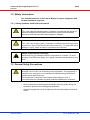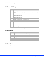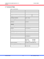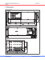
1
CPCI/CPCI Serial Hybrid System 3+1 U
(PICMG 2.30, CPCIS.0)
User’s Manual
Product No.:
24579-400
Doc-No: 63972-262_R1.0
January 04, 2010
Rev.
Date updated
Change
D1.0
February 16, 2009
Draft Release
R1.0
January 04, 2010
Initial Release
Impressum:
Schroff GmbH
D-75334 Straubenhardt, Germany
The details in this manual have been carefully compiled and
checked - supported by certified Quality Management System
to EN ISO 9001/2000
The company cannot accept any liability for errors or misprints.
The company reserves the right to amendments of technical
specifications due to further development and improvement of
products.
Copyright
© 2010
All rights and technical modifications reserved.
CPCI/CPCI Serial Hybrid System 3+1 U
24579-400
Table of Contents
1
2
3
4
Safety ................................................................................................................. 1
1.1
Intended Application ............................................................................................ 1
1.2
Safety Instructions ............................................................................................... 2
1.3
1.2.1
Safety Symbols used in this document .................................................. 2
General Safety Precautions................................................................................. 2
Product Definition............................................................................................. 3
2.1
References and Architecture Specifications ........................................................ 3
2.2
System Overview................................................................................................. 4
2.3
Subrack................................................................................................................ 4
2.4
CPCI/CPCI Serial Hybrid Backplane ................................................................... 5
2.5
2.4.1
Backplane topology ............................................................................... 6
Power Backplane................................................................................................. 8
2.6
Power Supply....................................................................................................... 9
2.7
2.6.1
CPCI Plug-In AC Power Supply........................................................... 10
2.6.2
Grounding/Earthing.............................................................................. 10
Cooling............................................................................................................... 11
Installation....................................................................................................... 12
3.1
General Installation Guidelines.......................................................................... 12
3.2
3.1.1
Unpacking ............................................................................................ 12
3.1.2
Ensuring Proper Airflow ....................................................................... 12
Rack-Mounting................................................................................................... 13
3.3
Initial Operation.................................................................................................. 13
Service ............................................................................................................. 14
4.1
Technical support and Return for Service Assistance ....................................... 14
4.2
Declaration of Conformity .................................................................................. 14
4.3
Scope of Delivery............................................................................................... 15
4.4
Accessories ....................................................................................................... 15
4.5
Spare Parts........................................................................................................ 15
5
Technical Data ................................................................................................ 16
6
Dimensions ..................................................................................................... 17
www.schroff.biz
I
R1.0, January 04, 2010
CPCI/CPCI Serial Hybrid System 3+1 U
24579-400
www.schroff.biz
II
R1.0, January 04, 2010
CPCI/CPCI Serial Hybrid System 3+1 U
Safety
24579-400
1 Safety
1.1 Intended Application
The CompactPCI (CPCI/CPCI PlusIO/CPCI Serial) system, described in this
manual, is intended as a platform for a microcomputer system based on the
CompactPCI Standards PICMG 2.0 Rev.3, CPCI PlusIO PICMG 2.30 and CPCI
Serial CPCIS.0.
The CPCI case systems are designed for protection class IP 20 and can be used
only in the resp. environments.
CPCI system subracks are not end-products, so there is no valid approval for
this unit. In order to enable stand-alone functionality, additional elements are
required. An operational system is achieved only by way of appropiate CPCI/
CPCI PlusIO/CPCI Serial boards.
The completion and final testing of the units have been carried out, or at least
supervised, by qualified technicians. These instructions are directed exclusively
to these qualified technicians i.e.engineers, trained and qualified electricians
etc.
Make sure that:
• the finished system complies with the safety regulations currently applicable
in the country it is going to be used.
• the finished system complies with all other regulations and specifications at
the place and country of use, e.g. interference limits, approval by the telecommunications authorities.
www.schroff.biz
1
R1.0, January 04, 2010
CPCI/CPCI Serial Hybrid System 3+1 U
Safety
24579-400
1.2 Safety Instructions
The intended audience of this User’s Manual is system integrators and
hardware/software engineers.
1.2.1 Safety Symbols used in this document
Hazardous voltage!
This is the electrical hazard symbol. Familiarise yourself with the danger of
electrical voltages and the safety precautions to avoid accidents before
starting to work with parts that carry dangerous voltages.
Caution!
This is the user caution symbol. It indicates a condition where damage of the
equipment or injury of the service personnel could occur. To reduce the risk of
damage or injury, follow all steps or procedures as instructed.
Danger of electrostatic discharge!
Static electricity can damage sensitive components in a system. To avoid
damage, wear ESD wrist straps or at regular intervals touch blank enclosure
parts.
1.3 General Safety Precautions
Warning!
Voltages over 60 VDC can be present in this equipment. This equipment is
intended to be accessed, to be installed and maintained by qualified and
trained service personnel only.
This equipment is designed in accordance with protection class 1!
It must therefore be operated only with protective GND/earth connection!
• Service personnel must know the necessary electrical safety, wiring and
connection practices for installing this equipment.
• Install this equipment only in compliance with local and national electrical
codes.
www.schroff.biz
2
R1.0, January 04, 2010
CPCI/CPCI Serial Hybrid System 3+1 U
Product Definition
24579-400
2 Product Definition
The Schroff CPCI/CPCI PlusIO system consists of:
• A shielded subrack with front and rear card cage for
3 U boards according to IEEE 1101.x, IEC 20297.x and the CompactPCI
Standards PICMG 2.0 Rev.3, PICMG 2.30 CPCI PlusIO and CPCI Serial
(CPCIS.0)
• An 8 slot 3 U CPCI/CPCI Serial hybrid backplane (23007-601)
• An 1 slot 3 U Power Backplane with P47 connector
• A CPCI plug-in power supply (250 W) with wide range input and P47
connector
• Power input module with IEC 320-C14 connector, mains/line switch, mains/
line filter and fuses
• Fan Tray with 3 axial Fans for the active cooling of the boards and the power
supply
2.1 References and Architecture Specifications
• User Manual CPCI Backplanes
Order no.: 73972-101
• User Guide Schroff CPCI/CPCI Serial Hybrid Backplanes 23007-601
Order no.: 63972-273
• User Manual Power Backplane 23098-105
Order no.: 73972-072
• User Manual 19“ Power Supply 13100-141
Order no.: 73972-077
Further information can also be found in the catalogue „Electronic Packaging“
and on the internet under www.schroff.biz
www.schroff.biz
3
R1.0, January 04, 2010
CPCI/CPCI Serial Hybrid System 3+1 U
Product Definition
24579-400
2.2 System Overview
Figure 1: System Overview
12309829
1
250 W CPCI Power Supply
4
Front panel 3 U, 44 HP
2
CPCI/CPCI PlusIO Backplane
5
Fan Tray with 3 fans
3
Front Card cage with guide rails
2.3 Subrack
The 4 U chassis is based on the Schroff europacPRO system with EMC
shielding. The front card cage enables the assembly of:
• 3 CPCI peripheral boards (3 U, 4 HP, 160 mm deep)
• 1 CPCI PlusIO CPU board (3 U, 4 HP, 160 mm deep)
• 4 CPCI Serial peripheral boards (3 U, 4 HP, 160 mm deep)
• 3 CPCI Rear I/O Boards (3 U, 4 HP, 80 mm deep)
Note: The backplane supports Rear I/O only at the CPCI peripheral slots.
Rear I/O at the 4 CPCI Serial slots is possible, when the backplane is equipped
with the respective connectors (assembly option).
The lower guide rails of the card cage are equipped with ESD clips.
Variations
The Schroff assembly service can customize your system with:
• Different Backplane configurations
• Drive mounting cassettes
• Special power supplies
More information in the catalogue or at www.schroff.biz
www.schroff.biz
4
R1.0, January 04, 2010
CPCI/CPCI Serial Hybrid System 3+1 U
Product Definition
24579-400
2.4 CPCI/CPCI Serial Hybrid Backplane
Figure 2: Backplane front and rear view
www.schroff.biz
5
R1.0, January 04, 2010
CPCI/CPCI Serial Hybrid System 3+1 U
Product Definition
24579-400
2.4.1 Backplane topology
The CPCI/CPCI Serial hybrid backplane is splitted into a CPCI and a CPCI
Serial section with a shared CPCI PlusIO system slot in the middle between the
CPCI and CPCI Serial section.
The former Rear I/O pins of the system slot connector P2 are used for the
routing of serial links (SATA, USB2, PCIe, ETH) to the J1 and J6 connectors of
the CPCI Serial slots as defined in the PICMG 2.30 CPCI PlusIO specification.
Ethernet is implemented by 4 differential pairs to support 10/100/1000/
10GBase-T.
Rear I/O at all CPCI peripheral slots at connector P2. Rear I/O at the CPCI Serial
slots (connectors 5-J2...8-J5) is possible as an assembly option.
Applicable Specifications:
PICMG 2.0 R3.0 CPCI Core Specification
PICMG 2.01 R2.0 Hot Swap
PICMG 2.09 R1.0 System Management Bus
PICMG 2.10 R1.0 Keying
PICMG 2.30 CPCI PlusIO
PICMG CPCI Serial (CPCIS.0)
More information in the manual for the backplane order no.: 63972-273
Figure 3: Backplane serial link routing
www.schroff.biz
6
R1.0, January 04, 2010
CPCI/CPCI Serial Hybrid System 3+1 U
Product Definition
24579-400
Table 1: Pinout CPCI PlusIO Connector 1-P2 (System Slot)
Pin
Z
A
B
C
D
E
F
22
GND
GA4
GA3
GA2
GA1
GA0
GND
21
GND
CLK6
GND
2_ETH_B+
1_ETH_D+
1_ETH_B+
GND
20
GND
CLK5
GND
2_ETH_B-
1_ETH_D-
1_ETH_B-
GND
19
GND
GND
GND
2_ETH_A+
1_ETH_C+
1_ETH_A+
GND
18
GND
2_ETH_D+
2_ETH_C+
2_ETH_A-
1_ETH_C-
1_ETH_A-
GND
17
GND
2_ETH_D-
2_ETH_C-
PRST#
REQ6#
GNT6#
GND
16
GND
4_PE_CLK-
2_PE_CLK+
DEG#
GND
reserved
GND
15
GND
4_PE_CLK+
2_PE_CLK-
FAL#
REQ5#
GNT5#
GND
14
GND
3_PE_CLK-
1_PE_CLK+
4_PE_CLKE#
SATA_SCL
reserved
GND
13
GND
3_PE_CLK+
1_PE_CLK-
3_PE_CLKE#
SATA_SDO
SATA_SL
GND
12
GND
4_PE_Rx00+
1_PE_CLKE#
2_PE_CLKE#
SATA_SDI
4_SATA_Rx+
GND
11
GND
4_PE_Rx00-
4_PE_Tx00+
4_USB2+
4_SATA_Tx+
4_SATA_Rx-
GND
10
GND
3_PE_Rx00+
4_PE_Tx00-
4_USB2-
4_SATA_Tx-
3_SATA_Rx+
GND
9
GND
3_PE_Rx00-
3_PE_Tx00+
3_USB2+
3_SATA_Tx+
3_SATA_Rx-
GND
8
GND
2_PE_Rx00+
3_PE_Tx00-
3_USB2-
3_SATA_Tx-
2_SATA_Rx+
GND
7
GND
2_PE_Rx00-
2_PE_Tx00+
2_USB2+
2_SATA_Tx+
2_SATA_Rx-
GND
6
GND
1_PE_Rx00+
2_PE_Tx00-
2_USB2-
2_SATA_Tx-
1_SATA_Rx+
GND
5
GND
1_PE_Rx00-
1_PE_Tx00+
1_USB2+
1_SATA_Tx+
1_SATA_Rx-
GND
4
GND
VIO
1_PE_Tx00-
1_USB2-
1_SATA_Tx-
reserved
GND
3
GND
CLK4
GND
GNT3#
REQ4#
GNT4#
GND
2
GND
CLK2
CLK3
SYSEN#
GNT2#
REQ3#
GND
1
GND
CLK1
GND
REQ1#
GNT1#
REQ2#
GND
Table 2: Pinout Connector x-P1 (Legacy CPCI Slots)
Pin
Z
A
B
C
D
E
F
25
GND
+5V
REQ64#
ENUM#
+3.3V
+5V
GND
24
GND
AD[1]
+5V
VIO
AD[0]
ACK64#
GND
23
GND
+3.3V
AD[4]
AD[3]
+5V
AD[2]
GND
22
GND
AD[7]
GND
+3.3V
AD[6]
AD[5]
GND
21
GND
+3.3V
AD[9]
AD[8]
M66EN
C/BE[0]#
GND
20
GND
AD[12]
GND
VIO
AD[11]
AD[10]
GND
19
GND
+3.3V
AD[15]
AD[14]
GND
AD[13]
GND
18
GND
SERR#
GND
+3.3V
PAR
C/BE[1]#
GND
17
GND
+3.3V
IPMB_SCL
IPMB_SDA
GND
PERR#
GND
16
GND
DEVSEL#
GND
VIO
STOP#
LOCK#
GND
15
GND
+3.3V
FRAME#
IRDY#
GND
TRDY#
GND
14
GND
GND
13
GND
GND
12
GND
11
GND
10
9
GND
AD[18]
AD[17]
GND
AD[21]
GND
C/BE[3]#
8
GND
AD[26]
7
GND
AD[30]
6
GND
REQ0#
5
GND
BRSVP1A5
4
GND
IPMB_PWR
3
GND
INTA#
2
GND
TCK
+5V
TMS
TDO
TDI
GND
1
GND
+5V
-12V
TRST
+12V
+5V
GND
www.schroff.biz
AD[16]
GND
GND
+3.3V
AD[20]
AD[19]
GND
GND
AD[23]
GND
AD[22]
GND
GND
VIO
AD[25]
AD[24]
GND
AD[29]
AD[28]
GND
AD[27]
GND
GND
+3.3V
CLK0
AD[31]
GND
BRSVP1B5
RST#
GND
GNT0#
GND
HEALTHY#
VIO
INTP
INTS
GND
INTB#
INTC#
+5V
INTD#
GND
7
C/BE[2]#
GND
R1.0, January 04, 2010
CPCI/CPCI Serial Hybrid System 3+1 U
Product Definition
24579-400
Table 3: Pinout Connector x-J6 (CPCI Serial ETH Connector)
Pin
A
B
C
D
E
F
2
GND
2_ETH_A+
1
1_ETH_A+
1_ETH_A-
G
H
I
2_ETH_A-
GND
2_ETH_B+
GND
1_ETH_B+
1_ETH_B-
J
K
L
2_ETH_B-
GND
2_ETH_C+
GND
1_ETH_C+
1_ETH_C-
2_ETH_C-
GND
2_ETH_D+
2_ETH_D-
GND
1_ETH_D+
1_ETH_D-
GND
8
7
6
5
4
3
Table 4: Pinout Connector x-J1 (CPCI Serial Base Connector)
Pin
A
6
GND
B
C
D
E
F
G
5
PE_Rx00+
PE_Rx00-
GND
PE_Tx00+
PE_Tx00-
GND
4
GND
USB2+
USB2-
GND
PE_CLK+
PE_CLK-
GND
SATA_Rx+
SATA_Rx-
GND
SATA_Tx+
SATA_Tx-
3
n.c.
n.c.
GND
n.c.
n.c.
GA1
SATA_SDI
SATA_SDO
GA2
SATA_SCL
SATA_SL
GA3
2
GND
IPMB_SCL
IPMB_SDA
GND
GND
RST_IN#
WAKE_IO#
GND
PE_CLKE#
1
IPMB_PWR
STNDBY
GA0
+12V
+12V
+12V
GND
+12V
+12V
GND
H
I
J
GND
+12V
K
L
GND
GND
GND
GND
GND
Pinout IPMB/Utility connectors
IPMB Connector
Pin
1
Utility Connector
Pin
IPMB_SCL
1
GND
2
GND
2
+5 V
3
IPMB_SDA
3
+12 V
4
IPMB_PWR
4
FAL#
5
-12 V
5
6
DEG#
7
+3.3 V
8
PRST#
2.5 Power Backplane
The 3 U / 8 HP Power Backplane supports pluggable CPCI PSUs with P47
connector. The Power Backplane provides 2 disk drive power connectors and
supports parallel operation by connecting the current share bus.
More information in the backplane‘s user manuals order no.: 73972-072 and
73972-101
www.schroff.biz
8
R1.0, January 04, 2010
CPCI/CPCI Serial Hybrid System 3+1 U
Product Definition
24579-400
2.6 Power Supply
Hazardous voltage!
Parts of the power supply may be exposed with hazardous voltage. Always
remove mains/line connector before carry out any assembly work.
Caution!
Your system has not been provided with a AC power cable. Purchase a
AC power cable that is approved for use in your country. The AC power cable
must be rated for the product and for the voltage and current marked on the
product's electrical ratings label. The voltage and current rating of the cable
should be greater than the ratings marked on the product.
The CPCI system is powered by a CPCI plug-in power supply with wide range
input (100 - 240 VAC).
The power supply is plugged-in in a dedicated slot at the left front side. The
power supply contact via a 47-position connector to a Power backplane.
The power input is provided by an AC mains/line module with IEC 320-C14
connector, integrated mains/line fuses and line filter.
The fuse rating is 4 A slow blow.
Figure 4: AC mains/line module
12309010
1
2
www.schroff.biz
Fuse holder
Mains/line switch
3
9
AC Connector (IEC320-C14)
R1.0, January 04, 2010
CPCI/CPCI Serial Hybrid System 3+1 U
Product Definition
24579-400
2.6.1 CPCI Plug-In AC Power Supply
Figure 5: Power Supply
10006814
Table 5: Data AC Power Supply
e
Input voltage nominal
100 - 240 VAC
Mains Frequency
50 / 60 Hz
Output (max.)
250 W
Output voltages
3.3
5.0
12.0
-12.0
-
V
V
V
V
40
40
5.5
2
A
A
A
A
Ripple
<1%
Dynamic response
< 1 % or 60 mV
Recovery time to within 1%
< 300 µsec
Overvoltage protection
for all voltages
120 – 130 % U > 5 Vr
Overcurrent protection
105 – 130 % of rated output current
Hold-up time
>= 20 ms
More information in the user manual order no.: 73972-077
2.6.2 Grounding/Earthing
Caution!
The unit is designed in accordance with protection class 1! It must therefore be
operated with protective earth/GND connection. Use only a three conductor
AC power cable with a protective earth conductor that meets the IEC safety
standards!
www.schroff.biz
10
R1.0, January 04, 2010
CPCI/CPCI Serial Hybrid System 3+1 U
Product Definition
24579-400
2.7 Cooling
The boards and the power supply are cooled by forced air convection through
three 12 VDC axial fans (140 m³/h (85 cfm)).
The fans are located in a hot-swappable fan tray.
The operating temperature is from 0°C to 50°C.
Caution!
To maintain proper airflow, all open slots must be covered with filler panels.
The filler panel should include an airflow baffle that extends to backplane.
Figure 6: Airflow
12309847
www.schroff.biz
11
R1.0, January 04, 2010
CPCI/CPCI Serial Hybrid System 3+1 U
Installation
24579-400
3 Installation
3.1 General Installation Guidelines
3.1.1 Unpacking
Caution!
When opening the shipping carton, use caution to avoid damaging the system.
Consider the following when unpacking and storing the system:
• Leave the system packed until it is needed for immediate installation.
• After unpacking the system, save and store the packaging material in case
the system must be returned.
If the packaging is damaged and possible system damage is present, report to
the shipper and analyze the damage.
3.1.2 Ensuring Proper Airflow
• Maintain ambient airflow to ensure normal operation. If the airflow is blocked
or restricted, or if the intake air is too warm, an over temperature condition
can occur.
• Ensure that cables from other equipment do not obstruct the airflow through
the systems.
• Use filler panels to cover all empty chassis slots. The filler panel should
include an airflow baffle that extends to backplane. The filler panel prevents
fan air from escaping out of the front of an open slot.
Filler Panels and Air Baffles
Air baffles and front panels with air baffles are available in the Schroff catalogue
or at www.schroff.biz
www.schroff.biz
12
R1.0, January 04, 2010
CPCI/CPCI Serial Hybrid System 3+1 U
Installation
24579-400
3.2 Rack-Mounting
This subrack system can be installed in 19“ equipment racks. The rack must be
accessible from the front and rear for equipment installation.
Mounting Kit
A rack mounting kit comes with the system.
Mounting Instructions:
• Ensure that the rack is constructed to support the weight and dimensions of
the system.
• Install any stabilizers that came with your equipment rack before mounting
or servicing the system in the rack.
Load the rack from the bottom to the top, with the heaviest system at the bottom,
avoid uneven mechanical loading of the rack.
3.3 Initial Operation
Warning!
This equipment is intended to be accessed, to be installed and maintained by
qualified and trained service personnel only.
This eqipment is designed in accordance with protection class 1!
It must therefore be operated only with protective GND/earth connection!
• Ensure that the system has not been damaged during transport, storage or
assembly.
• Check the Protective Earth (PE) resistance, should be < 0,1 Ohm.
• Switch on the system and check all CPCI voltages directly on the
backplane connectors before the board assembly.
Note: Io3 (12 V output) > Io4 (-12 V output)!
• Plug-in the boards
• Cover all open Slots with filler panels.
www.schroff.biz
13
R1.0, January 04, 2010
CPCI/CPCI Serial Hybrid System 3+1 U
Service
24579-400
4 Service
4.1 Technical support and Return for Service Assistance
We generally recommend to return the complete system. For all product returns
and support issues, please contact your Schroff sales distributor or
www.schroff.biz.
We recommend that you save the packing material. Shipping without the original
packing material might void the warranty.
4.2 Declaration of Conformity
SCHROFF CompactPCI systems are developed and manufactured according
to EN 60950-1.
SCHROFF CompactPCI systems are not end-products with independent
functionality as described in the definition of the EMC regulations, and therefore
a CE marking is not required. However, when CPCI/CPCI Serial cards are
assembled according to specification, the systems fulfill the requirements in
accordance with EMC Directive 2004/108/EG and Low-voltage Directive
2006/95/EG.
Interference resistance and interference emissions are factors which are heavily
influenced by the type and quantity of CPCI cards used in the system assembly.
Through the use of high quality line filters and EMC optimized enclosure design,
SCHROFF offers CPCI systems which serve as an ideal base for system
integrators, which comply with the prescribed limits of EN 6100-6-3 and
EN 61000-6-2
The systems are generally equipped with power supplies which possess
CE markings in accordance with EN 60950-1, EN 61000-6-3, EN 61000-6-2).
Before delivery a high-voltage, protective earth and functionality test is carried
out on each individual system.
www.schroff.biz
14
R1.0, January 04, 2010
CPCI/CPCI Serial Hybrid System 3+1 U
Service
24579-400
4.3 Scope of Delivery
Quantity
Description
1
Shielded europacPRO chassis 4 U / 84 HP with front handles
1
CPCI/CPCIPlusIO/CPCI Serial backplane (PICMG2.0 R.3.0, PICMG 2.30, PICMG CPCIS.0), 8
slot 3 U
1
Power Backplane with P47 Connector
1
Front card cage for max. 8 boards 3 U 160 mm deep
IEEE guide rails inc. ESD clips)
1
Rear card cage for max. 3 CPCI peripheral boards 3 U 80 mm deep
IEEE guide rails inc. ESD clips
1
250 W CPCI plug-in power supply with input range of 100 VAC to 240 VAC
4 voltages: 3,3 V / 40 A; 5 V / 40 A; 12 V / 5.5 A; -12 V / 2 A)
1
Complete AC/DC cabling
1
Fan Tray 1 HP with 3 fans 140 m³/h (85 cfm) each
2
Front panels 3 U, 44 HP
1
Front panel 3 U, 20 HP
1
Air baffle 3 U, 160 mm
1
19“ Rack mounting kit
Please order the power cable separately.
4.4 Accessories
Order No.
Description
20848-75x
Front panels for Rear I/O Boards, dimensions see catalogue
24579-033
Air filter kit
20848-7xx
Slot covers with front panel and EMC shielding for vacant slots. For dimensions, please see
catalogue.
34562-8xx
Slot covers for vacant slots. For dimensions, please see catalogue.
24579-03x
Printed Circuit Board covers (solder side covers). For dimensions, please see catalogue
4.5 Spare Parts
On request.
www.schroff.biz
15
R1.0, January 04, 2010
CPCI/CPCI Serial Hybrid System 3+1 U
Technical Data
24579-400
5 Technical Data
Table 6: Technical Data
Dimensions
Height
4U
Width
482.60 mm (19“)
Depth (Card cage)
275 mm
Depth (Overall with handles)
322 mm
Weight
Completely assembled
approx. 7,5 kg
Power Supply
Input Voltage
100 VAC to 240 VAC
Frequency
50 / 60 Hz
Power input
up to 250 W
Cooling
3 x 12 VDC fans
140 m³/h (85 cfm) each, free blow
Ambient Temperature
Operation
+0 °C to +50 °C
Storage
-40 °C to +85 °C
Humidity
Admissible humidity
30 % to 80 %, non-condensing
EMC, fulfils requirements for:
Transient Emissions
EN 61000-6-3
Interference Resistance
EN 61000-6-2
Safety
4,3 kVDC
2,2 kVDC
0,7 kVDC
0,7 kVDC
Test voltages according to EN 60950
Input - Output:
Input - PE:
Output - PE:
Output - Output:
Shock and vibration:
EN 60068-2-6 and EN 60068-2-27
Electromagnetic Shielding
Shielding attenuation
www.schroff.biz
typ. 40 dB at 1 GHz if shielded front
panels are used.
16
R1.0, January 04, 2010
CPCI/CPCI Serial Hybrid System 3+1 U
Dimensions
24579-400
6 Dimensions
Figure 7: Dimensions
www.schroff.biz
17
R1.0, January 04, 2010
CPCI/CPCI Serial Hybrid System 3+1 U
Dimensions
24579-400
www.schroff.biz
18
R1.0, January 04, 2010
SCHROFF GMBH
Langenalberstr. 96-100
D-75334 Straubenhardt
www.schroff.biz
Tel.: + 49 (0) 7082 794-0
Fax: +49 (0) 7082 794-200