1
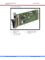
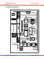
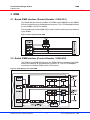
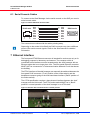
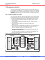
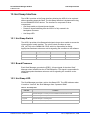
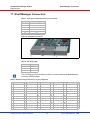
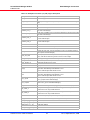
Shelf Manager ShMM-ACB-V
User’s Manual
Product Number:
21596-291
21596-292
Doc-No: 63972-243
Revision: R1.0, September 24, 2008
Rev.
Date updated
Change
R1.0
September 24, 2008 Initial Release
Impressum:
Schroff GmbH
D-75334 Straubenhardt, Germany
The details in this manual have been carefully compiled and
checked - supported by certified Quality Management System
to EN ISO 9001/2000
The company cannot accept any liability for errors or misprints.
The company reserves the right to amendments of technical
specifications due to further development and improvement of
products.
Copyright
© 2008
All rights and technical modifications reserved.
Schroff Shelf Manager ACB-V
21596-291/ -292
Table of Contents
1
2
Safety ................................................................................................................. 1
1.1
Safety Symbols used in this document................................................................ 1
1.2
General Safety Precautions................................................................................. 1
1.3
References and Architecture Specifications ........................................................ 2
1.4
Terms and Acronyms........................................................................................... 2
Product Definition............................................................................................. 3
2.1
ACB-V Product Overview .................................................................................... 5
2.2
Front Panel Components..................................................................................... 6
3
Shelf Manager Installation ............................................................................... 7
4
ACB-V Block Diagram ...................................................................................... 8
5
IPMB................................................................................................................... 9
6
5.1
Bused IPMB Interface (Product Number: 21596-291) ......................................... 9
5.2
Radial IPMB Interface (Product Number: 21596-292) ......................................... 9
RS-232 Interfaces............................................................................................ 10
6.1
Serial Console Cables ....................................................................................... 11
7
Ethernet Interface ........................................................................................... 11
8
Shelf Manager and Shelf Alarm Panel .......................................................... 12
9
Master-Only I²C Bus ....................................................................................... 13
10
Power Supply .................................................................................................. 15
10.0.1
10.0.2
10.0.3
11
DC-DC Converter................................................................................. 15
Input Fuses .......................................................................................... 16
Voltage and Fuse Monitoring ............................................................... 16
Fan Control...................................................................................................... 17
11.1 Schroff Fan Trays .............................................................................................. 18
11.1.1
11.1.2
Control characteristics (examples)....................................................... 18
Block Diagram Fan Tray - Shelf Manager............................................ 19
12
Hardware Address .......................................................................................... 20
13
RESET.............................................................................................................. 21
13.1 Reset Input / Output........................................................................................... 21
14
Redundancy Control ...................................................................................... 22
14.0.1
15
Hardware Redundancy Interface ......................................................... 22
Hot Swap Interface ......................................................................................... 23
15.1 Hot Swap Switch................................................................................................ 23
15.2 Board Presence ................................................................................................. 23
15.3 Hot Swap LED ................................................................................................... 23
www.a-tca.com / www.schroff.biz
1
R1.0, September 24, 2008
Schroff Shelf Manager ACB-V
21596-291/ -292
16
Telco Alarms ................................................................................................... 24
17
Shelf Manager Connectors ............................................................................ 25
18
Technical Data ................................................................................................ 29
www.a-tca.com / www.schroff.biz
2
R1.0, September 24, 2008
Schroff Shelf Manager ACB-V
Safety
21596-291/ -292
1 Safety
The intended audience of this User’s Manual is system integrators and
hardware/software engineers. This manual describes the hardware
features of the Schroff ACB-V Shelf Manager. The software features are
detailed in the ShMM-500 documentation from Pigeon Point Systems and
the Schroff firmware release notes.
1.1 Safety Symbols used in this document
Hazardous voltage!
This is the electrical hazard symbol. It indicates that there are dangerous
voltages inside the Shelf.
Caution!
This is the user caution symbol. It indicates a condition where damage of the
equipment or injury of the service personnel could occur. To reduce the risk of
damage or injury, follow all steps or procedures as instructed.
Danger of electrostatic discharge!
The Shelf contains static sensitive devices. To prevent static damage you must
wear an ESD wrist strap.
1.2 General Safety Precautions
Warning!
Voltages over 60 VDC can be present in ATCA Shelves. As defined in the
PICMG 3.0 Specification, this equipment is intended to be accessed, to be
installed and maintained by qualified and trained service personnel only.
• Service personnel must know the necessary electrical safety, wiring and
connection practices for installing this equipment in a telecommunication
environment.
• Install this equipment only in compliance with local and national electrical
codes.
• For additional information about this equipment, see the PICMG 3.0
Specification (www.picmg.com).
www.a-tca.com / www.schroff.biz
1
R1.0, September 24, 2008
Schroff Shelf Manager ACB-V
Safety
21596-291/ -292
1.3 References and Architecture Specifications
• Pigeon Point Systems IPM Sentry Shelf-External Interface Reference
(www.pigeonpoint.com)
• Pigeon Point Systems Shelf Manager User Guide
(www.pigeonpoint.com)
• PICMG® 3.0 AdvancedTCA® Base Specification
(www.picmg.com)
• PICMG® Engineering Change Notice ECN 3.0-2.0-00
• Analog Devices ADM1024 Reconfigurable Remote Temperature Sensor and
Supply Voltage Monitor
• Analog Devices ADM1026 Highly Integrated Thermal and System Monitor
• Philips Semiconductors PCA9545 4-Channel I2C with interrupt logic and
reset
• Philips Semiconductors PCA9555 16-bit I2C and SMBus I/O port with
interrupt
• National Semiconductor LM75 Digital Temperature Sensor and Thermal
Watchdog with Two-Wire Interface
1.4 Terms and Acronyms
Table 1: Terms and Acronyms
Term
Definition
ATCA
Advanced Telecom Computing Architecture
Backplane
Passive circuit board providing the connectors for the front boards. Power distribution,
management and auxiliary signal connections are supported
CDM
Chassis Data Module
Chassis
Enclosure containing subrack, Backplane, boards, cooling devices, PEMs, same as Shelf
CMM
Chassis Management Module, same as Shelf Manager
ECN
Engineering Change Notice
ESD
Electrostatic Discharge
ETSI
European Telecommunications Standards Institute
FRU
Field Replaceable Unit
IPMB
Intelligent Platform Management Bus
IPMC
Intelligent Platform Management Controller
IPMI
Intelligent Platform Management Interface
PCB
Printed Circuit Board
PEM
Power Entry Module
RTC
Real Time Clock
RTM
Rear Transition Module
Shelf
See Chassis
VRTN
Voltage Return
www.a-tca.com / www.schroff.biz
2
R1.0, September 24, 2008
Schroff Shelf Manager ACB-V
Product Definition
21596-291/ -292
2 Product Definition
The Schroff Shelf Manager ACB-V is a 78 mm x 280 mm board that fits into a
dedicated Shelf Manager slot in a Schroff ATCA Shelf.
The Shelf Manager has two main responsibilities:
1 Manage/track the FRU population and common infrastructure of a Shelf,
especially the power, cooling and interconnect resources and their usage.
2 Enable the overall System Manager to join in that management/tracking
through the System Manager Interface, which is typically implemented over
Ethernet.
The Shelf management based on the Pigeon Point Shelf management solution
for AdvancedTCA products.
The Shelf management software executes on the Pigeon Point Shelf
Management Mezzanine 500 (ShMM-500), a compact SO-DIMM form-factor
module, installed on the ACB-V carrier board.
The ACB-V carrier board includes several on-board devices that enable different
aspects of Shelf management based on the ShMM-500. These facilities include
I²C-based hardware monitoring/control and GPIO expander devices.
The ACB-V also provides the Fan Controller for up to 9 Fans and individual
Ethernet connections to both Base Hubs (ShMC cross connect), according to
PICMG Engineering Change Notice ECN 3.0-2.0-001
The Shelf Manager communicate inside the Shelf with IPM controllers over the
Intelligent Platform Management Bus (IPMB). The Shelf Manager also provides
an IPMB interface for the non-intelligent FRUs in a Schroff Shelf. The Shelf
Manager communicate with the non-intelligent FRUs over I²C busses and
expose the sensors for these FRUs at IPMB address 0x20.
Shelf Manager with bused IPMB: 21596-291 (Product Number)
21596-300 (Catalog Number with packaging)
Shelf Manager with radial IPMB: 21596-292 (Product Number)
21596.301 (Catalog Number with packaging)
www.a-tca.com / www.schroff.biz
3
R1.0, September 24, 2008
Schroff Shelf Manager ACB-V
Product Definition
21596-291/ -292
Figure 1: Schroff Shelf Manager
12708845
1
Extraction handle
5
Backplane Connector (J2)
2
ShMM-500
6
Backplane Connector (J1)
3
RTC Backup Capacitor
7
Fixing screw
4
ACB-V Carrier Board
www.a-tca.com / www.schroff.biz
4
R1.0, September 24, 2008
Schroff Shelf Manager ACB-V
Product Definition
21596-291/ -292
2.1 ACB-V Product Overview
• 78 mm x 280 mm board
• SODIMM 144-pin socket with ShMM-500 Shelf Management Mezzanine
Card from Pigeon Point Systems
• Dual RS-232 serial ports
• Dual 10/100 Ethernet interfaces
• IPMB-A/B interfaces with bused or radial topology
• Reset push button
• Master-only I²C bus populated with hardware monitoring/control, GPIO and
bus switch devices
• Power supply voltage monitoring
• On-board temperature monitoring
• Detection of hardware address with parity
• Injector/Ejector handle with Hot Swap switch
• Hot swap LED
• Capacitor for the ShMM-500 RTC and ADM1026 intrusion detection
• Hardware redundancy interface with dedicated communication paths
between dual Shelf Managers for redundant operation
• Interrupt requests for the ShMM-500 generated by on-board and off-board
devices
• Status indication for important interfaces, using on-board and off-board
LEDs
• Fan Controller for up to 9 fans
• Redundant –48 VDC inputs with on-board power regulation
www.a-tca.com / www.schroff.biz
5
R1.0, September 24, 2008
Schroff Shelf Manager ACB-V
Product Definition
21596-291/ -292
2.2 Front Panel Components
Figure 2: Shelf Manager Front Panel Components
12708844
1
Fixing screw
6
RESET push button
2
ETH 0 Ethernet Service Connector
(RJ45)
7
Shelf Manager Status LED (red)
ETH 0 Link/Activity LED (yellow)
8
3
- Red = Out of Service (OOS)
- On = Link
- Solid Green = in Service, active
Shelf Manager
- Off = No Link
- Blinking = in Service, Backup Shelf
Manager
- Blinking = Activity
4
Shelf Manager Status LED (green)
ETH 1 Link/Activity LED (yellow)
- On = Link
9
Hot Swap Switch
- Activated by extraction handle
- Off = No Link
- Blinking = Activity
5
Hot Swap LED (blue)
10 Extraction handle
- Solid Blue = ready to remove
- Blinking = Hot Swap is requested
- Off = No Hot Swap possible
www.a-tca.com / www.schroff.biz
6
R1.0, September 24, 2008
Schroff Shelf Manager ACB-V
Shelf Manager Installation
21596-291/ -292
3 Shelf Manager Installation
Danger of electrostatic discharge!
Static electricity can harm delicate components inside the Shelf. You must
wear an ESD wrist strap before exchanging any part or electric component!
Figure 3: Shelf Manager
12708847
The Shelf the Shelf Manager can be installed in horizontal or vertical position,
depending on the Shelf! (Figure shows horizontal position)
Install:
1 Insert the Shelf Manager into the guides and push it completely into the
Shelf. The lever (2) must be in position (C).
2 Close the lever (2) to position (A) and tighten the fixing screw (1).
3 The Shelf Manager is booting now. After aprox. one Minute the green Status
LED (5) indicates that the Shelf Manager is functional.
The Status LED of the active Shelf Manager is solid green, the Status LED of
the backup Shelf Manager is blinking.
Remove:
1 Unscrew the fixing screw (1).
2 Move the lever (2) to position (B) until the blue Hot Swap LED (3) starts
blinking.
3 When the Hot Swap LED is solid blue, move the lever (2) to position (C) and
pull out the Shelf Manager.
www.a-tca.com / www.schroff.biz
7
R1.0, September 24, 2008
Schroff Shelf Manager ACB-V
ACB-V Block Diagram
21596-291/ -292
4 ACB-V Block Diagram
Figure 4: ACB-V Block Diagram
12708846
www.a-tca.com / www.schroff.biz
8
R1.0, September 24, 2008
Schroff Shelf Manager ACB-V
IPMB
21596-291/ -292
5 IPMB
5.1 Bused IPMB Interface (Product Number: 21596-291)
The ShMM-500 provides two IPMBs. The IPMB-A and IPMB-B from the ShMM500 are routed directly to the Backplane connector. The ATCA Backplane buses
the two IPMBs to the ATCA boards.
The Active# signal of the ShMM-500 is used to switch on/off the pull-up resistors
of the IPMBs.
Figure 5: Block diagram bused IPMB
12708848
5.2 Radial IPMB Interface (Product Number: 21596-292)
The IPMB-A and IPMB-B buses from the ShMM-500 are routed through IPMB
buffers and switches to the Backplane connector J2. The ATCA Backplane
connects the individual IPMBs to the ATCA boards.
Figure 6: Shelf Manager with radial IPMB
12708849
www.a-tca.com / www.schroff.biz
9
R1.0, September 24, 2008
Schroff Shelf Manager ACB-V
RS-232 Interfaces
21596-291/ -292
6 RS-232 Interfaces
The ACB-V provides two RS-232 interfaces. The first serial port is implemented
using the built-in UART3 controller, the second serial port is implemented using
the built-in UART0 controller of the processor on the ShMM-500.
The on-board RS-232 transceiver on the ShMM-500 is always enabled because
the Ser_EN0 signal is pulled down on the ShMM-500.
The first serial interface provides a full set of RS-232 signals including modem
control. In a Schroff Shelf these signals are routed through the backplane
connector to the SAP. The SAP provides two 8-pin RJ45 modular receptacles
for the serial interfaces of both Shelf Manager.
The second serial interface does not provide modem control signals. These
signals are also routed to the backplane connector but not used in the Schroff
ATCA Shelves.
Figure 7: RS-232 Serial Ports
12706891
.
The serial console default configuration is:
• 115200 baud
• no parity
• 8 data bits
• 1 stop bit
www.a-tca.com / www.schroff.biz
10
R1.0, September 24, 2008
Schroff Shelf Manager ACB-V
Ethernet Interface
21596-291/ -292
6.1 Serial Console Cables
To connect to the Shelf Manager via the serial console on the SAP you need a
serial console cable.
Figure 8: RJ45 to DB9 Serial Console Cable
RJ45-male
1
8
RTS
DTR
TxD
GND
GND
RxD
DSR
CTS
8
6
2
5
5
3
4
7
1
2
3
4
5
6
7
8
CTS
DSR
RxD
GND
GND
TxD
DTR
RTS
DB9-female
5
1
9
6
12706929
The connectors are shown with the cables pointing away.
Depending on the model of the Shelf, the RJ45 connector may have a different
pinout of the serial console signals. Refer to the Shelf manual for detailed
information.
7 Ethernet Interface
The front panel ETH0 Ethernet connector is intended for service use only or for
debugging purposes in laboratory environment. The computer which is
connected to this interface must be located nearby the shelf manager with an
Ethernet cable that is not longer than 10m. The front panel Ethernet connector
MUST NOT be connected to a Telecommunication Network Circuit that leaves
the building.
The ETH0 interface of the shelf manager can manually be switched between the
front panel RJ45 connector (“Front”-position of the rocker-switch) and the
backplane connector going to the hub board base interface (“Back”-position of
the rocker-switch).
The ATCA specification requires a base channel interface between the shelf
manager and the Hub board. The ETH0 rocker-switch MUST be in “Back”position in normal operation of the shelf manager in an ATCA-shelf.
Figure 9: Switches S101 and S102 shown in default position
12708853
www.a-tca.com / www.schroff.biz
11
R1.0, September 24, 2008
Schroff Shelf Manager ACB-V
Shelf Manager and Shelf Alarm Panel
21596-291/ -292
8 Shelf Manager and Shelf Alarm Panel
Some Shelf Manager I/O functionalities have been moved to a separate Board
called Shelf Alarm Panel (SAP). The SAP provides the RJ45 Serial Console
connectors, the Telco Alarm Interface, user definable LEDs and custom specific
I/Os for the Shelf Manager. Only the active Shelf Manager has access to the
SAP and can switch the Alarms. The advantage of this approach is that the SAP
is separated from the Shelf Manager and can be located at a position at the
Chassis that is easy to reach and operate by service personnel.
The figure below shows the interconnection between the Shelf Manager and the
SAP. Please note that the design of the SAP is Shelf dependent, please see
your Shelf User Manual for the actual SAP-implementation in your Shelf.
Please see Chapter 16, "Telco Alarms" for detailed information concerning the
Telco Alarm interface and the user definable LEDs.
Figure 10: Connection between Shelf Manager and SAP
12706896
www.a-tca.com / www.schroff.biz
12
R1.0, September 24, 2008
Schroff Shelf Manager ACB-V
Master-Only I²C Bus
21596-291/ -292
9 Master-Only I²C Bus
The master-only I²C bus is used on the ShMM-500 for the RTC and SEEPROM
devices. The ACB-V carrier board also has a number of onboard I²C devices
connected to the master-only I²C bus. These devices are:
• PCA9554: reads the hardware address at the backplane connector
• PCA9555: monitor the presence signals from the PEMs, SAP, Airfilter and
Fan Trays (only bused version)
• PCA9539: radial IPMB enable and monitoring of presence signals (only
radial version)
• ADM1024/1026: monitor all Shelf Manager voltages, monitor/controls the
Fan Trays, provides the board temperature
• PCA9545: This 4-channel switch divides the I²C-bus in 4 channels to:
- the Shelf FRU SEEPROMs (Channel 1 and 2)
- the Fan Trays and Shelf temperature sensors (Channel 3)
- the PEMs (Channel 4)
Any individual SCx/SDx channel or combination of channels can be selected by
changing the contents of the programmable control register of the PCA9545.
Software running on the ShMM-500 is responsible for enabling/disabling
individual I²C channels at each particular time, so that no address conflict results
on the merged master-only I²C bus.
The master only I²C-bus is also buffered and then routed to the SAP providing
Telco Alarm signalizing (Channel 0).
The ’Active’ signal of the ShMM-500 is used to enable the I²C switch PCA9545
and the buffer, so that only the active Shelf Manager has access to the Shelf I²Cbus devices.
Figure 11: Master-Only I2C-bus
12706892
www.a-tca.com / www.schroff.biz
13
R1.0, September 24, 2008
Schroff Shelf Manager ACB-V
Master-Only I²C Bus
21596-291/ -292
The following table lists the I²C slave devices. The ShMM-500 on-board RTC
and SEEPROM and the Shelf devices are included for completeness.
Table 2: I²C-bus addresses of the Shelf
I²C addr.
ShMM
ACB-IV
SAP (CH 0)
CH 1
CH 2
CH 3
CH 4
PCA9555
Telco Alarms
0x44 / 22
PCA9554 HWAddr
0x46 / 23
0x48 / 24
PCA9555 Fan Tray 0 PCA9555
(left)
PEM A
0x4a / 25
PCA9555 Fan Tray 1 PCA9555
(center)
PEM B
0x4c / 26
PCA9555 Fan Tray 2
(right)
PCA9555 GPIO
(only bused
version)
0x4e / 27
0x58 / 2C
ADM1024
0x5c / 2E
ADM1026
0x90 / 48
LM75 temp sensor
0x92 / 49
LM75 temp sensor
0x94 / 4a
LM75 temp sensor
LM75 SAP
temperature
0x96 / 4b
0x98 / 4c
LM75 temp sensor
LM75 PEM A
0x9a / 4d
LM75 temp sensor
LM75 PEM B
0x9c / 4e
0xa0 / 50
LM75 temp sensor
SEEPROM
SEEPROM
CDM 1
0xa4 / 52
SEEPROM
CDM 2
SEEPROM
SAP
0xa6 / 53
0xa8 / 54
SEEPROM Fan Tray SEEPROM
0 (left)
PEM A
0xaa / 55
SEEPROM Fan Tray SEEPROM
1 (center)
PEM B
0xac / 56
SEEPROM Fan Tray
2 (right)
0xe0 / 70
PCA9545 I²Cbus switch
0xe8 / 74
PCA9539 radial
IPMB enable
(only radial version)
0xea / 75
PCA9539 radial
IPMB enable
(only radial version)
0xee / 77
PCA9539 radial
IPMB enable +
GPIO (only
radial version)
0xd0 / 68
RTC DS1337
www.a-tca.com / www.schroff.biz
14
R1.0, September 24, 2008
Schroff Shelf Manager ACB-V
Power Supply
21596-291/ -292
10 Power Supply
Figure 12: Power Supply Block Diagram
Capacitor
12708852
10.0.1 DC-DC Converter
The DC-DC converter on the ACB-V provides the power (3.3 V) for all on-board
devices and all off-board I²C devices inside the Shelf.
The 3.6 V local power is routed through two current limiting circuits to create two
redundant voltages, I2C_PWR_A and I2C_PWR_B.
I2C_PWR_A and I2C_PWR_B are routed to the backplane connector and used
to power I²C-devices on FRUs like Fan Tray, PEM or SAP. If one of these
voltages is short circuited on a chassis FRU or on the backplane, the short circuit
current is limited to 700 - 900 mA so that the Shelf Manager and the FRUs are
still fully operational.
www.a-tca.com / www.schroff.biz
15
R1.0, September 24, 2008
Schroff Shelf Manager ACB-V
Power Supply
21596-291/ -292
10.0.2 Input Fuses
The –48 V input circuits are protected by fuses, one in the supply and in the
return path.
Figure 13: Input fuses
12706897
The fuses are not user-serviceable.
10.0.3 Voltage and Fuse Monitoring
To detect a missing supply voltage as well as a blown fuse the ADM1026
provides voltage monitoring and control functions. The -48 VDC input voltage
before and after the fuses are connected to the ADM1026 chip through opticalisolation devices, all other voltages are connected directly.
Signal
Description
Device
Measurement
3.3V local
3.3 V supply for ACB-V on-board devices and ADM1026
Analog
for the ShMM-500
, pin 22
I2C_PWR_A
3.6 V supply redundant path A going to Shelf
I²C-devices
ADM1026
Analog
, pin 32
I2C_PWR_B
3.6 V supply redundant path B going to Shelf
I²C-devices
ADM1026
Analog
, pin 30
-48V_A_MONITOR
Indicates the presence of the –48 V_A /
VRTN_A at the backplane connector (J1).
ADM1026
Presence/Absence
, pin 46
-48V_A_FUSED_MONITOR
Indicates the presence of the –48 V_A /
VRTN_A after the ACB-V’s mains fuse.
ADM1026
Presence/Absence
, pin 44
-48V_B_MONITOR
Indicates the presence of the –48 V_B /
VRTN_B at the backplane connector (J1).
ADM1026
Presence/Absence
, pin 45
-48V_B_FUSED_MONITOR
Indicates the presence of the –48 V_B /
VRTN_B after the ACB-V’s mains fuse.
ADM1026
Presence/Absence
, pin43
VBAT
Backup-Battery voltage (Backup-Battery is
assembly option)
ADM1026
Analog
, pin 29
20V_MONITOR
Indicate the presence of the 20 V auxiliary
voltage supply generated on Fan Trays
ADM1026
Presence/Absence
, pin42
www.a-tca.com / www.schroff.biz
16
R1.0, September 24, 2008
Schroff Shelf Manager ACB-V
Fan Control
21596-291/ -292
11 Fan Control
The Shelf Manager provides fan control functionality through the ADM1024/
1026 system management controllers.
The fan speed is controlled by a 75 Hz PWM signal generated on the ADM1026.
The PWM output from the ADM1026 is buffered and enabled by the ShMM500’s ACTIVE# signal so that only the active Shelf Manager controls the fan
speed. The PWM signal is opto-isolated and routed to the backplane connector.
For voltage-regulated Fans the Shelf Manager provides a converter that
converts the PWM signal into a DC-voltage of 0 V to 10 V, referenced to the
ground level of the Fan Tray electronics (FAN_24V_RTN), which is also
available on the backplane connector.
The tachometer signals from the Fan Trays are routed through the backplane
connector opto-isolated to the digital inputs of the ADM1026. Because the
ADM1026 has only eight digital inputs with tachometer functionality, the signal
of a ninth Fan is routed to the ADM1024.
Three digital inputs to the ADM1026 (FANP0..2/GPIO9..GPIO11) are used to
detect the presence of Fan Trays. The Fan Tray grounds the signal to indicate
that it is installed.
The Shelf Manager’s fan tachometer inputs and fan control outputs (DC, PWM)
are optically isolated from primary voltages of the fans. The primary side of the
opto couplers is powered by a 24 V voltage (FAN_24V) which is generated on
the Fan Trays and routed together with the Fan Tray ground reference
(FAN _24V_RTN) to the Shelf Manager.
Figure 14: Shelf Manager Fan Control Block Diagram
ACB-IV Carrier Board
24 VDC generated on Fan Trays
20 V Power Supply
for Opto-couplers
Fan Tray Ground reference
Backplane Connector
(FAN_24V_RTN)
Au1550
ShMM-500 Connector
PWM Fan Control Signal
DC Fan Control Signal
Fan 1...8 Tachometer Signals
ADM1026
Fan 9 Tachometer Signal
ADM1024
12706894
www.a-tca.com / www.schroff.biz
17
R1.0, September 24, 2008
Schroff Shelf Manager ACB-V
Fan Control
21596-291/ -292
11.1 Schroff Fan Trays
11.1.1 Control characteristics (examples)
Figure 15: Fan Speed Control (PWM) for Shelves 11592-50x
Fan Speed (rpm)
5000
4000
3000
2000
1000
0
20
0
40
60
80
100
PWM (%)
Speed-up
Speed-down
12706964
Figure 16: Fan Speed Control (Control Voltage) for Shelves 11592-40x
Fan Speed (rpm)
6000
5000
4000
3000
2000
1000
0
0
2
4
6
Control Voltage (V)
8
10
12706965
Figure 17: Fan Tacho Signal Output
Tacho Signal
US High
US
t
US Low
t1
t2
1 rev
n max
Fan Speed
n
n min
t
12706966
www.a-tca.com / www.schroff.biz
18
R1.0, September 24, 2008
Schroff Shelf Manager ACB-V
Fan Control
21596-291/ -292
Table 3: Fan Tacho Data
Description
Tacho Type
Comment
Value
/2 (open collector)
Tacho operating
voltage
Tacho level low
up to 30 V
ISINK = 2 mA
< 0.4 V
Output Frequency
(2 x n) / 60 Hz
11.1.2 Block Diagram Fan Tray - Shelf Manager
Figure 18: Block Diagram Fan Tray - Shelf Manager
VRTN_A
Fan Tray
Shelf Manager
FAN_24V
24 V
Fan_Tach
Fan_Speed
PWM C
FAN_24V_RTN
Backplane Connector
48 V
Backplane Connector
VRTN_B
FAN_24V
24 V
20 V
Fan_Tach
Fan_Speed
PWM C
C
PWM E
E
Opto
Coupler
FAN_24V_RTN
Opto Fan_Tach
Coupler
DC
PWM
Opto
Coupler
- 48V_A
ACTIVE#
- 48V_B
Switch
PWM
ADM1026
12706966
www.a-tca.com / www.schroff.biz
19
R1.0, September 24, 2008
Schroff Shelf Manager ACB-V
Hardware Address
21596-291/ -292
12 Hardware Address
The PCA9554 on the ACB-V reads the hardware address and parity bit from the
backplane connector of the dedicated Shelf Manager slot.
Geographic address pins (HA[0], HA7) at the Backplane connector determine bit
0 and bit 7, bit 1 to bit 6 are hardware-coded on the Shelf Manager PCB. The
ShMM-500 software determines the hardware address by reading the input port
register of the PCA9554 at address 0x46.
Figure 19:
12706895
Table 4: Allocation PCA 9554 GPIO Signal Pins to hardware address bits
Switch/Source
Signal
GPIO
J2 pin D3
HA0
0x46-I/O0
Tied to ground
HA1
0x46-I/O1
Tied to ground
HA2
0x46-I/O2
Tied to 3.3V
HA3
0x46-I/O3
Tied to ground
HA4
0x46-I/O4
Tied to ground
HA5
0x46-I/O5
Tied to ground
HA6
0x46-I/O6
J1 pin E10
HA7/P
0x46-I/O7
Table 5: Shelf Manager Hardware and IPMB Addresses
HW-Addr.
IPMB-Addr.
HA[0]
HA7
Shelf Manager 1
0x08
0x10
GND
GND
Shelf Manager 2
0x09
0x12
n.c.
n.c.
www.a-tca.com / www.schroff.biz
20
R1.0, September 24, 2008
Schroff Shelf Manager ACB-V
RESET
21596-291/ -292
13 RESET
13.1 Reset Input / Output
The ACB-V provides a RESET push button on the front panel. It is connected to
the ShMM-500's /MR signal.
The /MR signal is driven low by the CPLD on the ShMM-500 when the watchdog
timer has expired. Additionally, the Shelf Manager may be reset by the user
using the RESET Push Button.
The ShMM-500 activates the /Reset output signal on the following condition:
Condition
Software/Hardware
Under software control
Software
Expiration of the watchdog timer
Hardware
Under-voltage condition or on-board LDO regulator failure
Hardware
Activation of the input /MR signal
Hardware
The /Reset signal clears all logic on the ACB-V. The duration of the low pulse on
the /Reset output is 200 ms.
www.a-tca.com / www.schroff.biz
21
R1.0, September 24, 2008
Schroff Shelf Manager ACB-V
Redundancy Control
21596-291/ -292
14 Redundancy Control
The Shelf Manager supports redundant operation with automatic switch-over
using redundant Shelf Managers. In a configuration where two Shelf Manager
are present, one acts as the active Shelf Manager and the other as a standby.
The Shelf Managers monitor each other and either can trigger a switchover if
necessary.
14.0.1 Hardware Redundancy Interface
The Shelf Manager provides a hardware redundancy interface with dedicated
communication paths between dual Shelf Managers for redundant operation.
The hardware redundancy interfaces of the Shelf Managers are as follows:
• Cross connected Shelf Manager present input (PRES_1#) and output
(PRES_GND#)
• Cross connected Shelf Manager health input (HLY_Input#) and output
(HLY_Output#)
• Cross connected negotiation input (SWR_Input#) and output
(SWR_Output#)
• Active output from the ShMM-500 (ACTIVE#) that is used by the ACB-V to
enable interfaces that must be exclusively driven by the active Shelf
Manager, specifically PWM and fan tachometer buffers
• Two status LEDs using the SWS_LED_G# (Green) and SWS_LED_R#
(Red) signals of the ShMM-500
• The PRES_1# signal is grounded on the redundant Shelf Manager. This
indicates both Shelf Managers the presence of the other.
Figure 20: Shelf Manager redundancy control
12708859
www.a-tca.com / www.schroff.biz
22
R1.0, September 24, 2008
Schroff Shelf Manager ACB-V
Hot Swap Interface
21596-291/ -292
15 Hot Swap Interface
The ACB-V provides a Hot Swap interface allowing the ACB-V to be replaced
without powering down the Shelf. The Hot Swap interface is implemented using
the on-ShMM-500 CPLD device. The interface is composed of three
components:
• Hot Swap switch at injector/ejector handle
• Presence signal indicating that the ACB-V is fully seated in its
backplane connector
• Hot Swap LED
15.1 Hot Swap Switch
The ACB-V provides a Hot Swap switch signal using a micro-switch to sense the
injector/ejector handle position. The micro-switch provides an input
(HS_LATCH) to the ShMM-500 CPLD, which is responsible for taking
appropriate hardware actions as well as signaling the condition to the software.
Micro-Switch
HS_LATCH Signal
HSL Bit in the CPLD
Condition
Open
High
0
Handle opened
Closed
Low
1
Handle closed
15.2 Board Presence
Each Shelf Manager grounds the PRES_1# input signal of the other Shelf
Manager when installed into the ATCA Backplane. This signal is responsible for
taking appropriate hardware action as well as signaling the condition to the
software.
15.3 Hot Swap LED
The Shelf Manager provides a a blue Hot Swap LED. The LED indicates when
it is safe to "remove" the Shelf Manager from a powered Shelf.
Table 6: Hot Swap LED
LED State
Condition
Off
The Shelf Manager is not ready to be removed/disconnected from the Shelf
Solid Blue
The Shelf Manager is ready to be removed/disconnected from the Shelf
Long-blink
The Shelf Manager is activating itself
Short-blink
Deactivation has been requested
www.a-tca.com / www.schroff.biz
23
R1.0, September 24, 2008
Schroff Shelf Manager ACB-V
Telco Alarms
21596-291/ -292
16 Telco Alarms
The Shelf Manager ACB-V can manage a Telco Alarm Interface with the
following components:
• Telco Alarm connector
• Telco Alarm LEDs
• Telco Alarm Cutoff push button
In Schroff Shelves these components are located on a separate board called
Shelf Alarm Panel (SAP). All three aspects of Telco interface are controlled by
a PCA9555 located on the SAP. The PCA 9555 is connected to the Shelf
Manager via an I²C connection at address 0x44. The Shelf management
software running on the ShMM-500 is responsible for:
• configuring the PCA9555 as inputs or outputs, as appropriate for the Telco
interface signal that a particular pin is attached to.
• reading and writing GPIO port registers at appropriate times.
The PCA9555 generates an active low interrupt output when one of the inputs
changes its value. That interrupt output is routed on the ACB-V onto the shared
interrupt line going to the INT# input of the ShMM-500. Software running on the
ShMM-500 is responsible for reacting to an input change when an interrupt is
triggered by the PCA9555.
For more information see Chapter 8, "Shelf Manager and Shelf Alarm Panel"
and the Chapter „SAP“ in the Shelf’s User Manual.
www.a-tca.com / www.schroff.biz
24
R1.0, September 24, 2008
Schroff Shelf Manager ACB-V
Shelf Manager Connectors
21596-291/ -292
17 Shelf Manager Connectors
Table 7: Front Panel 10/100 Ethernet Service Connector
Pin #
Ethernet Signal
1
TX+
2
TX-
3
RX+
4, 5
n.c.
6
RX-
7, 8
n.c.
Figure 21: Backplane Connectors
12706898
Table 8: Pin Staging (PS)
Pin#
length
A
8.25 mm
B
9.75 mm
C
11.25 mm
The Pin Staging (PS) is the length of the Pins of the connector at the Backplane
not at the Shelf manager.
Table 9: Backplane Signal Connector (J1) pin assignment
a
1 -48 V_A
PS
B
2 3 SHELF_GND
b
VRTN_A
PS
B
B
4 -
SHELF_GND
c
PS
B
NC
-
B
-
d
PS
B
-48 V_B
-
SHELF_GND
B
-
e
VRTN_B
PS
B
B
SHELF_GND
-
SHELF_GND
B
-
5 FAN_TACH0
A
FAN_TACH1
A
FAN_TACH2
A
FAN_TACH3
A
FAN_TACH4
A
6 FAN_TACH5
A
FAN_TACH6
A
FAN_TACH7
A
FAN_TACH8
A
PWM_C
A
7 FAN_SPEED
A
NC
A
FAN_24V
A
FAN_24V_RTN
A
PWM_E
A
8 -
-
-
-
-
9 PEM_PRES_A
A
SAP_PRES
A
SWR_Input#
A
HLY_Input#
A
SWR_Output#
A
10 TX+
A
TX-
A
HS_EN
A
HLY_Output#
A
HA7
A
11 AIR_FILT_PR
A
PEM_PRES_B
A
RX+
A
RX-
A
PRES_1#
A
www.a-tca.com / www.schroff.biz
25
R1.0, September 24, 2008
Schroff Shelf Manager ACB-V
Shelf Manager Connectors
21596-291/ -292
Table 10: Backplane Signal Connector (J2) pin assignment (Radial IPMB)
a
PS
b
PS
c
PS
d
PS
e
PS
f
GND
1 FAN_PRES0
A
TXD0
A
TXD1
A
FAN_PRES2
A
INT#
A
2 FAN_PRES1
A
DTR
A
Pres_GND
A
CI
A
DSR
A
3 CD
A
RTS
A
RXD1
A
HA[0]
A
CTS
A
4 RXD0
A
SDA_CH1
A
INV_ACTIVE
A
SDA_CH0
A
GND
A
5 SCL_CH1
A
SCL_CH0
A
RI
A
GND
A
SDA_CH3
A
6 S1_TX+
A
S1_TX-
A
GND
B
S2_TX+
A
S2_TX-
A
7 S1_RX+
A
S1_RX-
A
GND
B
S2_RX+
A
S2_RX-
A
8 SDA_CH4
A
SCL_CH4
A
SCL_CH3
A
SCL_CH2
A
I2C_PWR_B
A
9 IPMB_SCL_B15
A
IPMB_SDA_B15
A
IPMB_SCL_A15
A
IPMB_SDA_A15
A
SDA_CH2
A
10 IPMB_SDA_B16
A
IPMB_SCL_B16
A
IPMB_SDA_A16
A
IPMB_SCL_A16
A
I2C_PWR_A
A
11 IPMB_SDA_A3
A
IPMB_SDA_B3
A
IPMB_SCL_B3
A
IPMB_SDA_B8
A
IPMB_SCL_B8
A
12 IPMB_SCL_A3
A
IPMB_SDA_A5
A
IPMB_SCL_A5
A
IPMB_SDA_A8
A
IPMB_SCL_A8
A
13 IPMB_SDA_A1
A
IPMB_SDA_B7
A
IPMB_SCL_A1
A
IPMB_SDA_A10
A
IPMB_SCL_A10
A
14 IPMB_SCL_B7
A
IPMB_SDA_A7
A
IPMB_SCL_A7
A
IPMB_SDA_A6
A
IPMB_SCL_A6
A
15 IPMB_SDA_A9
A
IPMB_SDA_B14
A
IPMB_SCL_B14
A
IPMB_SDA_B10
A
IPMB_SCL_B10
A
16 IPMB_SCL_A9
A
IPMB_SDA_A4
A
IPMB_SCL_A4
A
IPMB_SDA_B6
A
IPMB_SCL_B6
A
17 CROSS_SDA_B
A
IPMB_SDA_B11
A
IPMB_SCL_B11
A
IPMB_SDA_B4
A
IPMB_SCL_B4
A
18 CROSS_SCL_B
A
IPMB_SDA_A11
A
IPMB_SCL_A11
A
IPMB_SDA_A14
A
IPMB_SCL_A14
A
19 IPMB_SDA_A13
A
IPMB_SCL_A13
A
IPMB_SCL_B12
A
IPMB_SDA_B12
A
IPMB_SDA_B9
A
20 IPMB_SDA_B1
A
IPMB_SCL_B1
A
CROSS_SCL_A
A
CROSS_SDA_A
A
IPMB_SCL_B9
A
21 IPMB_SDA_B13
A
IPMB_SDA_B5
A
IPMB_SCL_B5
A
IPMB_SDA_B2
A
IPMB_SCL_B2
A
22 IPMB_SCL_B13
A
IPMB_SDA_A12
A
IPMB_SCL_A12
A
IPMB_SDA_A2
A
IPMB_SCL_A2
A
PS
C
C
C
GND
C
C
GND
C
C
GND
C
C
GND
GND
GND
C
C
GND
C
C
GND
C
C
GND
C
C
GND
C
Table 11: Backplane Signal Connector (J2) pin assignment (Bused IPMB)
a
1 FAN_PRES0
PS
A
b
TXD0
PS
A
c
PS
A
TXD1
d
FAN_PRES2
PS
A
e
INT#
PS
f
PS
A
GND
C
2 FAN_PRES1
A
DTR
A
Pres_GND
A
CI
A
DSR
A
3 CD
A
RTS
A
RXD1
A
HA[0]
A
CTS
A
4 RXD0
A
SDA_CH1
A
INV_ACTIVE
A
SDA_CH0
A
GND
A
5 SCL_CH1
A
SCL_CH0
A
RI
A
GND
A
SDA_CH3
A
6 S1_TX+
A
S1_TX-
A
GND
B
S2_TX+
A
S2_TX-
A
7 S1_RX+
A
S1_RX-
A
GND
B
S2_RX+
A
S2_RX-
A
SCL_CH4
A
SCL_CH3
A
SCL_CH2
A
8 SDA_CH4
A
I2C_PWR_B
A
9
A
A
A
A
SDA_CH2
A
10
A
A
A
A
I2C_PWR_A
11
A
A
A
A
A
12
A
A
A
A
A
13
A
A
A
A
A
14
A
A
A
A
A
15
A
A
A
A
16
A
A
A
A
A
17 CROSS_SDA_B
A
A
A
A
A
18 CROSS_SCL_B
A
A
A
IPMB_SDA_A
A
19
A
A
A
I
A
A
20
A
A
A
CROSS_SDA_A
A
A
21
A
A
A
A
A
22
A
A
A
A
A
IPMB_SDA_B
www.a-tca.com / www.schroff.biz
A
IPMB_SCL_B
CROSS_SCL_A
26
IPMB_SCL_A
C
GND
C
C
GND
C
C
GND
C
C
GND
C
A
GND
GND
C
GND
C
C
GND
A
C
C
GND
C
C
GND
R1.0, September 24, 2008
C
C
Schroff Shelf Manager ACB-V
Shelf Manager Connectors
21596-291/ -292
Table 12: Backplane connector (J1) and (J2) pin description
-48V_A
-48 VDC supply A
-48V_B
-48 VDC supply B
AIR_FILT_PR
Air filter presence (grounded by air filter presence switch to detect a missing air
filter)
CD
Serial Interface 1 Carrier Detect
CI
Chassis Intrusion signal of ADM1026
CROSS_SCL_A
Serial Clock of IPMB-A, cross-connected on Backplane to serial clock of IPMBB of other Shelf Manager
CROSS_SCL_B
Serial Clock of IPMB-B, cross-connected on Backplane to serial clock of IPMBA of other Shelf Manager
CROSS_SDA_A
Serial Data of IPMB-A, cross-connected on Backplane to serial data of IPMB-B
of other Shelf Manager
CROSS_SDA_B
Serial Data of IPMB-B, cross-connected on Backplane to serial data of IPMB-A
of other Shelf Manager
CTS
Serial Interface 1 Clear To Send
DSR
Serial Interface 1 Data Set Ready
DTR
Serial Interface 1 Data Terminal Ready
FAN_24V
Auxiliary 24 VDC (max. 100 mA) generated on Fan Trays (Voltage supply for
opto-couplers on Shelf Manager)
FAN_24V_RTN
Return path (Ground reference) for the auxiliary 24 VDC, generated on Fan
Trays, used also as reference ground for the fan control voltage
FAN_PRES[0...2]
Fan Tray present (grounded on Fan Tray when present)
FAN_SPEED
DC for Fan Speed Control (0 V to 10 V, 10 mA)
FAN_TACH[0...8]
Tachometer signals from Fan Trays
GND
logic ground
HA[0]
Hardware address of Shelf Manager
- grounded: Shelf Manager IPMI address is 0x10
- open: Shelf Manager IPMI address is 0x12
HA7
Hardware address of Shelf Manager
- grounded: Shelf Manager IPMI address is 0x10
- open: Shelf Manager IPMI address is 0x12
HLY_Input#
Health input Shelf Manager (proprietary signal cross-connected on Backplane
to HLY_Output of other Shelf Manager)
HLY_Output#
Health output Shelf Manager (proprietary signal cross-connected on Backplane to HLY_Input of other Shelf Manager)
HS_EN
Tells the Shelf Manager that it is plugged in (Grounded on Backplane)
I2C_PWR_A
I2C_PWR_B
3.6 V (max. 500 mA) generated on Shelf Manager, redundant path A for Shelf
I2C-devices on Fan Trays, PEMs and SAP
3.6 V (max. 500 mA) generated on Shelf Manager, redundant path B for Shelf
I2C-devices on Fan Trays, PEMs and SAP
INT#
External Interrupt request (Master Only I2C-bus)
INV_ACTIVE
This ShMM is in active mode (inverted signal of ShMM)
IPMB_SCL_A_[1...16]
Serial Clock, IPMB-A
IPMB_SCL_B_[1...16]
Serial Clock, IPMB-B
IPMB_SDA_A_[1...16]
Serial Data, IPMB-A
IPMB_SDA_B_[1...16]
Serial Data, IPMB-B
www.a-tca.com / www.schroff.biz
27
R1.0, September 24, 2008
Schroff Shelf Manager ACB-V
Shelf Manager Connectors
21596-291/ -292
NC
not connected
PEM_PRES_[A, B]
PEM [A, B] presence signal (grounded on PEM when present)
PRES_1#
Shelf Manager board presence signal (proprietary signal cross-connected on
Backplane to PRES_GND of other Shelf Manager)
PRES_GND#
Shelf Manager presence ground (proprietary signal cross-connected on
Backplane to PRES_1# of other Shelf Manager)
PWM_C
Opto isolated PWM signal for fan speed control, collector
UCE0 = max. 70 V, Imax = 2 mA
PWM_E
Opto isolated PWM signal for fan speed control, emitter, connected to
FAN_24V_RTN on Backplane
RI
Serial Interface 1 Ring Indication
RTS
Serial Interface 1 Request To Send
RX(+-)
Ethernet interface (ETH1) to Hub-Slot (ShMC cross connect)
RXD0
Serial Interface 1 Receive Data
RXD1
Serial Interface 2 Receive Data (not used in Schroff Shelves)
S1_RX(+-)
Ethernet interface (ETH0)
S1_TX(+-)
Ethernet interface (ETH0)
S2_RX(+-)
USB interface, cross-connected on Backplane to S2_TX(+-) of other Shelf
Manager
S2_TX(+-)
USB interface, cross-connected on Backplane to S2_RX(+-) of other Shelf
Manager
SAP_PRES
Presence signal of SAP (Grounded on SAP when present)
SCL_CH0
Master Only-I2C-bus Channel 0 to SAP
SCL_CH1
Master-Only I2C-bus Channel 1
SCL_CH2
Master-Only I2C-bus Channel 2
SCL_CH3
Master-Only I2C-bus Channel 3
SCL_CH4
Master-Only I2C-bus Channel 4
SDA_CH0
Master Only-I2C-bus Channel 0 to SAP
SDA_CH1
Master-Only I2C-bus Channel 1
SDA_CH2
Master-Only I2C-bus Channel 2
SDA_CH3
Master-Only I2C-bus Channel 3
SDA_CH4
Master-Only I2C-bus Channel 4
SHELF_GND
Shelf Ground
SWR_Input#
Switchover signal from the other Shelf Manager (proprietary signal
cross-connected on Backplane to SWR_Output of other Shelf Manager)
SWR_Output#
Switchover signal to the other Shelf Manager (proprietary signal
cross-connected on Backplane to SWR_Input of other Shelf Manager)
TX(+-)
Ethernet interface (ETH1)
TXD0
Serial interface 1 Transmit Data
TXD1
Serial interface 2 Transmit Data (not used in Schroff Shelves)
VRTN_A
Voltage return supply A
VRTN_B
Voltage return supply B
www.a-tca.com / www.schroff.biz
28
R1.0, September 24, 2008
Schroff Shelf Manager ACB-V
Technical Data
21596-291/ -292
18 Technical Data
Table 13: Technical Data
Physical Dimensions
Height
2 U (Frontplate 10 mm)
Width
20 mm with EMC gaskets
Depth (PCB)
280 mm
Depth (with connectors and handle)
310 mm
Weight
Shipping weight completely assembled
without packaging
0.6 kg
Power
Input voltage
-40.5 VDC …. -72 VDC
Power dissipation
max. 10 W
Overcurrent Protection
500 mA Fuses on PCB
Environmental
Ambient temperature
-5°C…+55°C
Humidity
+5%...+85%, no condensation
www.a-tca.com / www.schroff.biz
29
R1.0, September 24, 2008
Schroff Shelf Manager ACB-V
Technical Data
21596-291/ -292
www.a-tca.com / www.schroff.biz
30
R1.0, September 24, 2008
SCHROFF GMBH
Langenalberstr. 96-100
D-75334 Straubenhardt
www.schroff.biz
www.a-tca.com
Tel.: + 49 (0) 7082 794-0
Fax: +49 (0) 7082 794-200