1
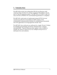
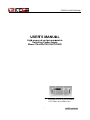
IT6 6533A USE ER MANUA AL U R’S MA USER ANUA AL High h-powerred and program p mmable Switching Pow wer supp ply Mod del IT65 532A/IT6533A/IT6523D Copyright 2014 All Rights Reservved Ver1.1/AP PR, 2014/ IT6500-1001 1 USER MANUAL M IT6 6533A USE ER MANUA AL About yo our safety .................................................................................................................. 3 Gene eral informattion ............................................................................................................................................. 3 Prote ection from electric e shocck........................................................................................................................... 3 Defin nition of userr .................................................................................................................................................. 3 Certificattion and Warranty W .................................................................................................... 4 Certiffication ........................................................................................................................................................... 4 Warra anty................................................................................................................................................................ 4 Limita ation of Warrranty ......................................................................................................................................... 4 Introducttion ........................................................................................................................... 4 Chapter1 1 Inspectio on and Insttallation ..................................................................................... 5 1.1 In nspection ....................................................................................................................................................... 5 1.2 Dimension D ...................................................................................................................................................... 5 Chapter2 2 Quick sta art ............................................................................................................. 7 2.1 description off front panell and rear pa anel .................................................................................................. 7 eyboard intrroduction ................................................................................................................................... 8 2.2 ke 2.3 VFD V indicator lamps desscription ................................................................................................................ 9 Chapter3 3 power-on n inspectio on ............................................................................................ 10 1 3.1 power on pre e-examinatio on ....................................................................................................................... 10 1 1.Initial pow wer source ..................... . ...................................................................................................... 10 2 2.System sselftest.................................................................................................................................... 10 3.2 Output O checkkout ......................................................................................................................................... 11 1 Voltage Ou utput Checkkout .................................................................................................................... 11 2 2.Output current checkkout ................................................................................................................... 11 Chapter4 4 Specifica ation ........................................................................................................ 12 1 4.1 Main M technica al paramete ers ...................................................................................................................... 12 4.2 Supplementa S al characteristics .................................................................................................................. 14 Chapter5 5 Basic Op perations ................................................................................................. 15 1 5.1 Local/Remote e.............................................................................................................................................. 15 S voltag ge ............................................................................................................................................ 15 5.2 Setting 5.3 Setting S current ............................................................................................................................................ 15 5.4 On/off O button ............................................................................................................................................... 16 5.5 Setting S value e/Actual valu ue ....................................................................................................................... 16 5.6 Voltage V and current c adjustment .............................................................................................................. 16 5.7 Save S operatio on ........................................................................................................................................... 16 5.8 Trigger T opera ation ........................................................................................................................................ 17 5.9 Menu M Operattion.......................................................................................................................................... 17 5.10 Protection Function F .................................................................................................................................. 22 K Lock Fu unction ................................................................................................................................... 22 5.11 Key 5.12 Rear termin nal function ............................................................................................................................. 22 Chapter6 6 Remote Control ................................................................................................... 23 2 6.1 Communicati C ion interface es ....................................................................................................................... 23 6.1.1 RS232 inte erface ...................................................................................................................................... 23 ace .......................................................................................................................................... 24 6.1.2 USB interfa 6.1.3 GPIB Interfface ......................................................................................................................................... 24 6.1.4 Ethernet intterface ................................................................................................................................... 25 S soft ftware and SCPI S comma and ................................................................................................ 25 6.2 Standard USER MANUAL M 2 IT6 6533A USE ER MANUA AL Abo out yo our safet s ty Pease revview the follo owing safetyy precaution ns before operating our equipment. e Gene eral in nform mation n The follow wing safety p precautions should be observed o beffore using th his product a and any asssociated instrumen ntations. Alth hough some e instruments s and accesssories would be used w with non-hazzardous voltages, there are sittuations whe ere hazardo ous condition ns may be present. p This produ uct is intend ded for use by b qualified personnel p w recognizze shock hazzards and arre familiar with who w the safetyy precautionss required to o avoid posssible injury. Read and fo ollow all installation, ope eration, and maintenan nce informattion carefullyy before using the product. Refer to o this manua al for comple ete product specificatiions. If the prod duct is used in a manner not specified, the prote ection provid ded by the p product may y be impaired. Before pe erforming any maintenan nce, disconn nect the line cord and alll test cabless. Protection n from m elec ctric s shock k Operatorss of this instrrument must be protecte ed from elecctric shock at a all times. T The responssible body must ensu ure that operators are prevented acccess and/orr insulated frrom every connection point. p In som me cases, connections must m be expo osed to pote ential human n contact. Prroduct opera ators in thes se b trained to o protect the emselves fro om the risk of o electric shock. If the circuit c is circumstances must be o operating at or above 1000 volts, no conductiive part of th he circuit ma ay be exposed. capable of Defin nition n of us ser Responsib ble body is the t individua al or group responsible r for the use and a mainten nance of equ uipment is operated within w its specifications and operating limits, an nd for ensuriing that operators are adequately trained. oduct for its intended function. Theyy must be tra ained in elecctrical safetyy procedures Operatorss use the pro and prope er use of the e instrument.. They must be protecte ed from electtric shock an nd contact with w hazardous live circuitts. Service iss only to be performed p b qualified service by s perssonnel. Safety sym mbols and te erms Connect it to t safety earth ground using u the wirre recomme ended in the user manual. The symb bol on an insstrument indicates that the t user sho ould refer to the operatin ng instructions located in the manua al. ge danger High voltag 3 USER MANUAL M IT6 6533A USE ER MANUA AL Certtifica ation and Warrranty y Certificatiion We certify y that this prroduct meet its published specificatiions at time of shipmentt from the fa actory. Warrranty This instru ument produ uct is warran nted againstt defects in m material and d workmansh hip for a perriod of one year from date of delivery. During g the warran nty period we e will, at its option, o eithe er repair or replace r products which w prove e to be defec ctive. For wa arranty service, with the exception of o warranty options, o this s product must m be returrned to a service facility y designated d by us. Custtomer shall prepay ship pping charge es by (and sh hall pay all d duty and tax xes) for prod ducts returne ed to the sup pplier for wa arranty servic ce. Except for f products returned r to ccustomer fro om another country, c sup pplier shall pay p for return n of products s to custome er. Limitation n of Warran W nty The foregoing warran nty shall not apply to deffects resultin ng from improper or inad dequate ma aintenance by b the Customer, Custom mer-supplied d software or o interfacing g, unauthoriz zed modifica ation or misu use, operation outside off the environ nmental spec cifications fo or the produc ct, or improp per site prep paration and maintenanc ce. Intro oduc ction IT6500A series is a flexiable f ran nge single output o high power supp ply.With wid de power ra anges from 3KW to 6KW,current 6 ts from 120A to 240A.S Standard RS232,USB, GPIB,RS485 and LAN N interfacess included on o the rear panel provide flexibilityy for remote e operation of the power supply.Its compact 4U(6KW)) size form ffactor make es it ideal for use in a standard 19--inch rack. (1)Autto-Range function (2)High Resolutio on Display (3)RS2 232/USBTM MC/GPIB/RS S485/LAN standard s intterfaces (4)Seq quence prog gramming (List mode) (5)OVP and OPP P protection mote sense e function (6)Rem (7)Inte elligent fanss control Model IT6523D IT6532A IT6533A Volltage 160 0V 80V V 160 0V USER MANUAL M ower Po 30 000W 60 000W 60 000W Current 120A 240A 120A 4 IT6 6533A USE ER MANUA AL Ch hapte er1 In nspe ection n and d Installattion Pow wer supply is an equ uipment with w high grrade of se ecurity. It h has a prottective earrth terminal..Please no ote the security label and instruc ctions in th he manual.. 1.1 In nspec ction The following f ste eps help you u verify that the t power supply is read dy for use. 1.check the t appeara ance If you u find any damage d of the t panel orr outline border,please contact with the local franchisers of ITECH or the service departmentt.Before you u get a positiive answer,p please do no ot return the e unit. 2.check the t accesso ories To ve erify that you u have receiived the follo owing items along with your y power supply.If something is missing,please contact with the nearest n franc chisers. □ one USB U cable □ one user’s u manual. □ AC in nput line □ one calibration c re eport 3.AC inpu ut 220VAC ± 10%, 47 to o 63 Hz 1.2 Dimen D nsion The dime ension of IT T6532A/IT65 533A/IT6523 3D 441.1mm mW×180mmH×463.5 55mmD Refer to th he following dimension drawing: 5 USER MANUAL M IT6 6533A USE ER MANUA AL unit:millim meter(mm) ) IT6532A/IT T6533A/IT65 523D dimen nsion drawing USER M MANUAL 6 IT6 6533A USE ER MANUA AL Cha apterr2 Qu uick startt This s chapter will w introduc ce the frontt panel,rea ar panel,ke eyboard fun nction and VFD displa ay function.To ensure e you have a quick un nderstandin ng of this product p be efore you using it. 2.2 Descr D iption n of frront panel and a re ear pa anel 1. 2. 3. 4. powe er supply sw witch VFD display board ating knob to o control volttage,coarse button,fine botton pulsa pulsa ating knob to o control currrent,coarse button,fine botton 5. 6. directtion key and d key functiion keys and d composite e key 7. nume eric key、 key 7 USER MANUAL M IT6 6533A USE ER MANUA AL 1. 2. 3. 4. 5. 6. 7. 8. 9. 10. 11. remo ote sense an nd output terrminals outpu ut terminal RS48 85 communication interfface (for facttory use only) fuse 5 interface DB25 fans B communica ation interface GPIB USB communica ation interfac ce RS23 32 communication interfface AC power input ssocket Etherr communica ation interface 2.2 keybo k oard in ntrodu uction n Keyboard d instructio ons as follow ws: keys s Name an nd function 0-9 Numeric c button Compos site function button OVP settting button,the button u used to set the ovp valu ue/menu fun nction button Menu which us sed to set the related pa arameters off power supp ply Voltage setting butto on,used to sset the outp put voltage value/set th he rising time V-set Slope and fall time t of volta age Current setting button,used to set the output current value/set th he maximum m I-set Pmax alue power va Callback k button,use ed to recall a saved settting parame eter/save bu utton,used to t Reca all Save save a setting s param meter Meter bu utton,used to o switch the display bettween actual value and setting value Mete er Local /switch to o the local mode m Confirm button,to co onfirm the se etting numbe ers or functio on/trigger bu utton,used to t Ente er Trigger provide a trigger single for voltage/current output(for o SC CPI comman nd) Output on/off o button n,used to co ontrol the ou utput status of power su upply/keyloc ck On/O Off Lock function button,used d to lock the front panel buttons Left and right direction button,us sed to adjus st the locatio on of the currsor Up and down dire ection button,used to select the items of th he menu or o e(decrease) the output voltage v and current valu ue increase USER MANUAL M 8 IT6 6533A USE ER MANUA AL Confirm button Quit buttton 2.3 VFD V in ndicattor lam mps d descrription n As follow ws: Chartt Func ction description C Chart Function description n OFF Powe er supply in off mode T Timer none CV Powe er supply in CV mode S Sense none CC Powe er supply in CC mode E Ext none * Open n the keylock function A Adrs Display 3 seconds on nce data reach erface communication inte Meterr “Mete er” button in n on mode R Rmt Remote control mode e Shift using g composite function E Error Error occu ur Rear Open n analogue function f P Prot Protection ns for OVP OTP O SRQ Sourrce inner req quest events s T Trig Trigger mo ode 9 USER MANUAL M IT6 6533A USE ER MANUA AL Cha apterr3 po ower--on in nspection n This chapter will introdu uce the pow wer-on che eck proced dure to ens sure the un nit is ready y for use.Itt includes two t parts:p pre-check and outputt check. 3.1 power p r on pre-ex p xamina ation Powe er on pre-examination in ncludes two parts:initial power supp ply and syste em selftest. 1.Initia al power source Use the t following g steps to he elp solve pro oblems you might encou unter when tturning on th he instrumen nt.If the unit can not be started s norm mally,please check acco ording to the following gu uidance. 1) Verify fy that there e is AC pow wer to the po ower supplly First, verify that tthe power co ord is firmly plugged into o the power receptacle on the rear panel of the e powe er supply. Yo ou should also make sure that the power p sourc ce you plugged the powe er supply intto is ene ergized. The en, verify tha at the powerr supply is tu urned on 2)Verifyy that the co orrect powe er-line fuse e is installed d. If the fuse was da amaged, ple ease see the e table below w to replace e the fuse for your powe er supply Fuse spec cification( (220VAC) model IT6532A 20 0A 250 0V IT6533A 20 0A 250 0V IT6523D 20 0A 250 0V 3) The way w to change the fus se Open n the plastic lid in the be elow of the power p input ssocket,you will w see the ffuse,and the en exchange ea good fuse e according to t the above e specificatio on. 2.Syste em selftes st When n you turn on the powerr supply,it wiill do the sysstem selftest. If the EEPROM was w damage ed, the VFD will display as follows: EE EPROM FAILURE If the latest opera ation data in n EEPROM is i lost, the V VFD will disp play as follow ws: C Config D Data Lo ost If the calibration data in EEP PROM is lostt, the VFD w will display as a follows: C Calibration n Data Los st If the factory calib bration data a in EEPROM M is lost, the e VFD will display as follows: F FactoryCa al.Data Los st If the e system settting data in EEPROM is s lost,the VF FD will display as follow ws: M Mainframe eInitializeL Lost If all is i normal,the e VFD will display d the voltage v and current c as th he following status: OF FF 0.000V 0.0W USER MANUAL M 0.000A 10 IT6 6533A USE ER MANUA AL 3.2 Outpu O ut checkoutt The following procedures check to ensure that the pow wer supply develops its rated outputs and a properrly respond ds to opera ation from the front panel. 1 Voltage e Output Ch heckout The following f ste eps verify ba asic voltage function with hout load. 1) Turn T on the power supp ply 2) Set S the output current( (≥0.1A) 3) Open O the ou utput P Press on/offf button,the CV C indicatorr lamp will be lit. 4) Open O the Me eter button 5) Set S the outpu ut voltage S different voltage and Set d check whether the VFD D display vo oltage is app proximate to the setting v voltage. 6) Ensure E the output o voltag ge can be ad djusted from m 0V to full ra ated value 2.Outpu ut current checkout c The follow wing steps check basic current c func ction with a short s across the power ssupply’s output 1) Turn T on the p power supply. 2) Disable D the output 3) 4) 5) 6) 7) Prress On/Offf key to ens sure that the e output is disabled. C Connect a sh hort across (+) and (-) ou utput terminals with an insulated i tes st lead. Us se a wire sizze sufficient to handle th he maximum m current. En nable the ou utput and op pen the Mete er function button b To o ensure the e CC indicattor lamp is lit Ad djust the currrent Sett different cu urrent values s and check k whether the e voltage dis splay is apprroximate to 0V,the 0 display cu urrent value is approxim mate to the setting value En nsure that th he current can be adjusted from zerro to the full rated value e. Tu urn off the po ower supply y and remov ve the short wire w from the output terminals. 11 USER MANUAL M IT6 6533A USE ER MANUA AL Chapter4 4 Spe ecific cation This s chapter will introduce the rated r volta age,currentt, power a and many other ma ain paramete ers of IT65 500A. 4.1 Main M t techn ical param p meters parameters Rated va alue ( 0 °C - 40 0 °C) (in re emote sens se mode) Load reg gulation ± ±(%of output+offset) Line regula ation IT6532 2A voltage e currentt powerr 0~80V 0~240A 0~6000W W voltage e <0.05%+40m mV currentt ≤0.1%+60m mA voltage e currentt voltage e <0.02%+20m mV <0.02%+30m mA currentt voltage e currentt 6mA 2mV 6mA voltage e ≤0.05%+40m mV currentt ≤0.2%+0.1% %FS Readback accuracy a (25°C±5 5°C) (%of outpu ut+offset) voltage e 0.05%+40m mV currentt ≤0.2%+0.1% %FS Ripp ple voltage e ≤100mVp--p currentt 240mArms Tem co oefficient (0 °C ~ 40 °C) ±((%of output+ +offset) voltage e 0.02%+40m mV currentt ≤0.05%+20m mA Readba ack Tem coeffficient ±(% %of output+o offset) voltage e 0.02%+40m mV ((%of output+ +offset) Setting resolution Readback rresolution Setting ac ccuracy (w within twelve e months) (25°C±5°C C) (%of outpu ut+offset) (20Hz ~20M MHz) 2mV currentt ≤0.05%+20m mA dimension n(mm) weight( (Kg) USER MANUAL M 439mmW W×180mmH×5 534mmD 34Kg 12 IT6 6533A USE ER MANUA AL parameters IT6533 3A voltage e currentt powerr 0~160V 0~120A 0~6000W W voltage e <0.05%+40m mV currentt ≤0.1%+40m mA voltage e currentt voltage e <0.02%+20m mV <0.02%+20m mA currentt voltage e currentt 3mA 4mV 3mA voltage e ≤0.05%+40m mV currentt ≤0.2%+0.1% %FS Readback accuracy a (25°C±5 5°C) (%of outpu ut+offset) voltage e 0.05%+40m mV currentt ≤0.2%+0.1% %FS Ripp ple voltage e ≤150mVp--p currentt 120mArms Tem co oefficient (0 °C ~ 40 °C) ±((%of output+ +offset) voltage e 0.02%+40m mV currentt ≤0.05%+20m mA Readba ack Tem coeffficient ±(% %of output+o offset) voltage e 0.02%+40m mV Rated va alue ( 0 °C - 40 0 °C) (in re emote sens se mode) Load reg gulation ± ±(%of output+offset) Line regula ation ((%of output+ +offset) Setting resolution Readback rresolution Setting ac ccuracy (w within twelve e months) (25°C±5°C C) (%of outpu ut+offset) (20Hz ~20M MHz) 4mV currentt ≤0.05%+20m mA dimension n(mm) weight( (Kg) 439mmW W×180mmH×5 534mmD 34Kg 13 USER MANUAL M IT6 6533A USE ER MANUA AL parameters IT6523 3D voltage e currentt powerr 0~160V 0~120A 0~3000W W voltage e <0.05%+40m mV currentt ≤0.1%+40m mA voltage e currentt voltage e <0.02%+20m mV <0.02%+20m mA currentt voltage e currentt 3mA 4mV 3mA voltage e ≤0.05%+40m mV currentt ≤0.2%+0.1% %FS Readback accuracy a (25°C±5 5°C) (%of outpu ut+offset) voltage e 0.05%+40m mV currentt ≤0.2%+0.1% %FS Ripp ple voltage e ≤150mVp--p currentt 120mArms Tem co oefficient (0 °C ~ 40 °C) ±((%of output+ +offset) voltage e 0.02%+40m mV currentt ≤0.05%+20m mA Readba ack Tem coeffficient ±(% %of output+o offset) voltage e 0.02%+40m mV Rated va alue ( 0 °C - 40 0 °C) (in re emote sens se mode) Load reg gulation ± ±(%of output+offset) Line regula ation ((%of output+ +offset) Setting resolution Readback rresolution Setting ac ccuracy (w within twelve e months) (25°C±5°C C) (%of outpu ut+offset) (20Hz ~20M MHz) 4mV currentt ≤0.05%+20m mA dimension n(mm) weight( (Kg) 439mmW W×180mmH×5 534mmD 34Kg 4.2 Suppl S emen ntal ch haractteristics State storage capac city 100 sets Recommended calib bration freq quency once a ye ear Cooling style s fans Operation n Temperatture 0 to 40 °C C Storage Temperatur T re -20 to 70 °C. Environm mental Cond ditions Designed for indoor use u and operated at max ximum relattive humidity y of 80% USER MANUAL M 14 IT6 6533A USE ER MANUA AL Ch hapte er5 Basic B c Ope eratio ons This s chapter describes d in n detail the e use of the e front-pan nel keys an nd shows how h they are a used to accomplish a h power su upply opera ation. This s chapter iss divided in nto the follo owing secttions: Local mod de/Remotte mode Setting voltage Setting current On/off Actual valu ue display//setting value dislay Adjustmen nt of curren nt/voltage/p power Save operration 5.1 Local/ L /Remo ote You can c switch frrom remote mode to loc cal mode by press + button ns. When n you turn on o the unit,itt will defaultt in local mo ode and all buttons are available.T That’s to say y,in remote mode,the m fron nt panel butttons can’t be b used.The e two operating modes can be switched through will not be e PC.When the operatin ng mode is changed,all the output parameters p effected. 5.2 Settin S g volttage The constant c volltage range is from 0V to t the maxim mum voltage value. It iss very easy for you to set s the consta ant voltage o utions to sett the constan nt voltage value.And wh hen you pre ess output. You have 3 solu V-set ,this , button w will be lit. (1)directly y input thro ough numb ber keys Input the value v you w want to set an nd then plea ase press (2)using knob k to sett value or butto on to confirm m. V Press V-set butto on Press butto on(coarse adjustment,c a change the value in integer bit)) or adjustmen nt,change th he value in decimal d bit),a and then rottate the knob to set the value (3)using left l and righ ht direction n key to sett value button(fine V Press V-set butto on Press button(fine butto on(coarse adjustment,c a change the value in integer bit)) or adjustmen nt,change th he value in decimal bitt),and then through leftt and right kkeys to adju ust the curs sor location,press ▲and d ▼ to set the voltage value S g current 5.3 Settin The consttant current range is fro om 0A to the maximum m voltage value. It is verry easy for you y to set the constant current outp put. You have 3 solutio ons to set the constantt current va alue.And wh hen you pre ess I-set ,this , button w will be lit. 15 USER MANUAL M IT6 6533A USE ER MANUA AL (1)directly y input thro ough numb ber keys Input the value v you w want to set an nd then plea ase press (2)using knob k to sett value or butto on to confirm m. Press I-set butto on butto on(coarse adjustment,c a change the value in integer bit)) or Press nt,change th he value in decimal d bit),a and then rottate the knob to set the value adjustmen (3)using left l and righ ht direction n key to sett value button(fine Press I-set butto on Press button(fine butto on(coarse adjustment,c a change the value in integer bit)) or adjustmen nt,change th he value in decimal bitt),and then through leftt and right kkeys to adju ust the curs sor location,press ▲and d ▼ to set the curren nt value 5.4 On/off O f butto on On/O Off button is used to control the output statte of power supply. If On/Off bu utton is lit,th his represents output is on.And o in on n mode,the indicator lam mp(CC/CV) will w be lit. t the DC source and d product under test ha ave been co onnected we ell before yo ou Note:please ensure that O press On/Off butto on. 5.5 Settin S g valu ue/Ac ctual v value Me eter button is used to o switch the display b between ac ctual value and setting g value.When Meter button Meter button b is lit,tthis represe ents that VFD board dissplay is actu ual value.Reversely,if is dark,VF FD board dissplay is corresponding to t setting value. 5.6 Voltag V ge and d currrent adjustment Powe er supply’s output o volta age and Electronic load d’s resistanc ce determine e the output current.On nly when the actual curre ent value is lower than the setting current valu ue,can the p power supply y works in CV C d the CV ind dicator lamp will be lit. mode.And If the e actual currrent value is s limited by the setting current valu ue or rated current,then n IT6500A will w change to o CC mode.A And the CC indicator lam mp will be litt. 5.7 Save S o opera ation IT6500A can c enable you to save e some often n used para ameters in nonvolatile m memory up to 100 sets.S So that you can c recall th he paramete ers quickly.The following g ways can help you acchieve the sa ave and rec call operations s:by pressiing compos site button + Recall (Save) button n or throug gh command *SAV,*RC CL.Save operation should work in wiith GROUP.E Each GROU UP can save e 10sets,IT65 500A includes 10 GROU UP from 0-9. Save para ameters include setting voltage and d setting currrent Save method: nter button to all +numberr keys 1…9,and then pre Using g composite e button + Reca essing En save the preset p value e into specified memory region. Recall Using g b button +num mber keys 1-9,and 1 then pressing Enter bu utton to rec call the saved parameters from spec cified memo ory region. USER MANUAL M 16 IT6 6533A USE ER MANUA AL 5.8 Trigge T er ope eration n Pleas se select the e trigger mod de in the me enu setup be efore you sta art a trigger operation. Beforre you want to run a list sequence file,please prrovide a trigg ger signal by y press composited butto on Enter E Enter + (trrigger).Durin ng the list file e running,the e button (trig gger) will be alight. 5.9 Menu M Operation 1. Menu description Pres ss + (Me enu) to enter the menu function.Vie f w the meun in VFD,and d use right and Enterr left directtion key or knob to scroll throug gh the complete menu u list as following.If prress button,you u could get the t selected d menu func ction.Press SYSTEM MENU Initialize Power -O On Trigger Memory SYSTEM M Buzzer Communiication back to o the previo ous menu se election page e. System me enu Init Setup Initialize the system No D not initialize the system Do Yes Initialize the system P-OUT S power on Set n parameterrs Rst(Def) R Restore to fa actory defau ults Sav0 TRIGGER SOURCE R Remain last shutdown p parameters Manual(Deff) M Manual trigge er Bus MEMORY Group = 0 BUS trigger B W Work with re ecall button tto recall 100 0sets s saved param meters 0 0:represents s 1-10sets; ; 1 1:represents s:11-20sets, , b parity of reasoning by r BUZZER ST TATE S status of buzzer Set On(Def) e enable the buzzer b function Off d disable the buzzer b function COMMUNIC CATION Select communication intterface S S Select RS232 2 interface RS232(Def)) according to your test deman nds and combine with direction keys k to select RS232 configure 4 4800 , 8, N(None parity), 1 , Addr... S trigger mode Set 9 9600 , O(odd parity), 2 , (0~31) 1 19200 , E(even pa arity) 3 38400 5 57600 1 115200 S Select USB in nterface USB S Select GPIB interface GPIB Addr=0 sett the commu A unication add dress S Select Ethern net interface ETHERNET T 17 USER MANUAL M IT6 6533A USE ER MANUA AL G Gateway= 19 92.168.0.1 IP P= 192.168.0.125 M Mask= 255.255.255.0 S Socket Portt= 30000 RETURN METER R Return to me eter interface Off(Def) D not use automatic retu Do urn Delay R Return after 5 seconds P-On Outpu ut P Power on outtput status se et Off(Def) T status is OFF when p The power on Last The status wiill keep the ssame as the last set T b before powerr off Volt-Max Vmax=161.0 00V S max value of voltage Set Volt-Min Vmin= 0.00V V S min value Set e of voltage ReturnMe eter P-Out CONFIG MENU CONFIG LIST MEN NU Off LIST INFO Exit LIST mode m Recall RECALL LIIST R Recall list filess Recall List File= F 1 S Select recalled list file(0--9) EditList Edit LISTfile es Edit Seq Edit sequen nce Power Inffo… Information of this mach hine Model:IT6 65xxx Ver:0.02-0 0.02 01234567 789AF Model, softw ware version, series num mber No Inform mation Reserved d for calibrattion information Note:p press + (Menu)to view w the menu u items,prress operatio on.Besides s,press state. to o quit men nu button can en nable you u quit the e function n operatio on u functio on 2.Menu Initializze setting g(> Initialize ) This item can enable all setup of the menu to o factory deffault.Press to confirm. Triggerr Mode( (>Trigger) This item m is used to sset the trigge er source,to be Manual tigger mode e or Bus trigg ger mode.It often be used to provide e a trigger signal for a list operation n.In Manual o option,press s + Enter (Trrigger) could d generate a trigger sig gnal.If in BU US option,this indicates in i BUS trigg ger mode. Factory default d is Manual optio on. USER MANUAL M 18 IT6 6533A USE ER MANUA AL Save Group G Op peration( (Memorry) Power source ca an save 100 0sets parameters in nonvolatile mem mory by the save group setting.This s operation n provides th he customerr with a conv venient and quick save/recall using condition. all (Save)+0 + Reca 0-9 numeric GRP0:sav ve(recall) po ower source parameters s in 0-9 sets.Press ecall +0-9 numeric keys( Re n keys s to recall th he paramete ers) GRP1:sav ve(recall) pa arameters in 10th -19th se ets.Press + Recall (save)+numbers1 1-9 to save the paramete ers( Recall +numbers1 1-9 to recall parameters).Under this s condition,number “1” re epresents to o t save or re ecall the 10th parameterrs.Number “2” representts to save or recall the e eleventh paramete er.GRP2-GR RP9 can be understande u ed in the sam me manner. ound Sett(>Buzzer) Key So This item can se et the buzzer state.On option o indica ates that whe en you push h buttons,the e buzzer will sound.OF FF option indicates that the buzzer function is disabled.Fac d ctory defaultt is On optio on. max,Vmiin) Outputt voltage set(>Vm The voltage can n be set bettween 0A and rated vo oltage.Pressing + (M Menu) to enttry into Config item,and then using knob or diirection key ys to select Vmin option under Lim mit item.Pre ess Enter button,then Ente er button,yo set the minimum voltage.After pressing b ou could set the maximu um voltage.Affter the settting operatio on,the volta age can only y be adjusted within th he limitation n of Vmin and Vmax. Default Vmax V valu ue is the rated r volta age,and Vm min is 0V. n Set(>C Communication ) Communication Underr this item,yo ou can set th he concrete communica ation mode.T This unit hass provided multiple m cation interfa aces:RS232 2/USB/GPIB B/ETHERNET.Of which,tthe GPIB arre addressab ble from communic 0-31.The baudrate op ptions of RS232 are 480 00,9600,192 200,38400,57600,115.2K K.Data bit is s 8bits.Parity y bit has thrree options:N NONE,ODD D,EVEN.Plea ase ensure the t configurration consisstency betwe een our instrunme ent and PC,sso that you could c have a successful communica ation. peration((>List ) List Op Please preset p the e trigger mode m beforre you run n a list file e. Press item >Sys stem,press +(Menu)) to enter the e menu setu up.Then press up and down buttons s to select Enter to confirm.Afte er that,press s up and dow wn buttons to t select >Trigger item to set the trig gger mode,a and press en nter to confirm. 19 USER MANUAL M IT6 6533A USE ER MANUA AL Operatio on steps 1. Press s + (Men nu) to enter the menu setup 2. VFD display SYS STEM,press 3. VFD display OFF F,press 4. VFD display File Name xx---,input the sequence s file e name(1---10) to be ed dited 5. VFD display Listt Power =xx xxxxW----,in nput the max ximum powe er value 6. VFD display Listt Repeat =xxxxx----,inp put the repea at running tim mes(1---655 535) of LIST file 7. VFD display Acttive Seq:09 987654321 ----select the e sequence e name to be linked in one LIST to select LIST,presss Enter to t confirm to o select EDIITLIST item,press En nter to conffirm file.Affter you sele ect the sequ uence numbe er,then acco ording numb ber will change to “Y” 8. VFD display Se eq n Repea at:xxxxx----,s set the rep peat runing times of tthe linked sequence s n(1----65535) 9. Save list to File?----,press or to finish the edit ope eration Sequen nce Operration(>S Seq ) Please preset p the e trigger mode m beforre you ediit a sequence file Press + stem,press item >Sys (Menu) to enter th he menu se etup.Then press p up and d down butttons to sele ect Enter to confirm.Afte er that,press s up and down buttons to select >T Trigger item to set the trig gger mode,a and press en nter to confirm. You cou uld edit vario ous kinds of sequence with w variable e ouput by se etting up eve ery step’s pa arameters.The parameters includes step-voltage s e,step-curren nt,step-time and time un nit.Besides tthe fomer pa arameters,yo ou so edit whether continu ue to the ne ext step,repe eat times an nd whether to save the e file.After yo ou should als finish the sequence file edition,if the t instrume ent receives a trigger sig gnal,the sequ uence file will w begin to run hing the sequence, or re eceive anoth her trigger siignal.The following will ttake a three sequence file f until finish to be an example: e Operatio on Steps: : 1. Press s + (Menu u) to enter th he menu setup 2. VFD display SYS STEM,press 3. F,press VFD display OFF 4. q Name: xx,input the se equence nam me to be edited (1-10) VFD display Seq 5. ctive Step::0987654321, activate the seque ence steps,when step is activate ed, VFD display Ac to select LIST,presss Enter to o confirm to o select EDIITSeq,press s Enter to confirm. er will chang ge to “Y”(for example:se elect step 1) accorrding numbe 6. t the voltage of activvated sequence step(ffor VFD display Se eq Step n Voltage =xxxxxV,se = mple:3V) exam 7. VFD display Se eq Seq n Current =xxxxxA,set = t the curre ent of activvated seque ence step(ffor USER MANUAL M 20 IT6 6533A USE ER MANUA AL exam mple:1A) 8. VFD display Seq S Step n Width =xxxxxms,,set the duration of time of the t activated e:3000ms) step(1---65535),((for example 9. S Step n Slope=x xxxxxms.Se et the volttage rising time of the t activate ed VFD display Seq 30ms step(0-65535),for example:3 10. VFD display Actiive Step:0987654321,in nput step nu umber,for ex xample:2 11. VFD display Seq q Step n Volttage=xxxxxV V,set the voltage of activ vated seque ence step(for example:5V) 12. VFD display Se eq Step n Current=xx xxxxA, set the curren nt of activatted sequence step n(ffor exam mple:4A) 13. VFD display Seq q Step n Wid dth=xxxxxm ms.for exam mple 3000ms s q Step n Slo ope=xxxxxm ms,for exam mple 30ms 14. VFD display Seq 987654321,fo for example 3 15. VFD display Actiive Step:09 16. VFD display Seq q Step n Volltage=xxxxx xV,for exam mple 7V 17. VFD display Seq q Step n Current=xxxxx xA,for exam mple 8A 18. VFD display Seq q Step n Wid dth=xxxxxm ms,for exam mple 3000ms s 19. VFD display Seq q Step n Slo ope=xxxxxm ms,for exam mple 30ms 20. VFD display Sav ve Seq To File?----Press s o or button to finish th he edition Trigger the sequence e file: 1. Press s 2. VFD display SYS STEM,press 3. F,press VFD display OFF 4. Press s + + (Menu u) to enter th he menu setup to select LIST,presss Enter to t confirm to o select CAL LLSeq,press Enter t confirm to (Triigger) button n to give a trrigger signal 21 USER MANUAL M IT6 6533A USE ER MANUA AL 5.10 Prote ection n Func ction IT650 00A has provided with OVP,OCP,OP O PP,OTP func ction. You could c set the e over voltag ge protectio on value by press p button.Man ny reasons could cause ea over volta age error.Forr example, caused c by in nternal defecct,misoperattion,or too high external voltage.Once the powerr supply is over voltage protected,w will the output be shut do own at once,,and “OVP” indicator lam mp will be lit. s fun nction of IT6500A is thatt it can enab ble you to se et the protecction delay time(Tovpdl t ly) One superior within the range of 1~ ~600ms. se avoid inputing a exte ernal voltage e higher than n 120% rate ed value of IT6500A,or the t instrume ent Pleas will be dam maged. When n the power source is in n OVP state,,you should check the external e causse first.Whe en the extern nal factors arre excluded,please pres ss ON/OFF button.Then n the unit co ould have a output volta age again.If in remote co ontrol mode e,you should d clear the OVP state,,then could you open tthe output by OUTP ON O command d. Abou ut OPP:IT650 00A will be over power protected iff the actual power is hig gher than Pm max which we w set in the menu.when n OPP is acttivated, the output o will tu urn off and “O OPP” will ap ppear on the e VFD. OTP point: 75℃ Lock Functtion 5.11 Key L + (Lock)) button can n enable you u to lock the e front pane el buttons,then VFD will display “*”.In keylock mode,all m butttons will no ot work exce ept ON/OFF F,Meter and On/Off (Lock) ( button will releas se the keyloc ck function. ess buttons.Re-pre + 5.12 Rear terminal fu unctio on Vo+,Vo o- : Vs+,Vss- : output termina als,the sam me with the e rear pane el output te erminals rem mote sense terminal,when using the remote e sense fun nction,please cut off the conn nection betw ween Vo+ an nd Vs+,so w will the line between b Vo o- and Vs- te erminals.Then exte ending lines from Vs+ to o the positivve terminal of o undertestted product and line fro om Vs- to the negattive terminal of the prod duct under te est. USER MANUAL M 22 IT6 6533A USE ER MANUA AL C Chaptter6 Rem mote Cont C rol 6.1 Comm C munic catio on inte erfac ces IT65 500A has five f standa ard commu unication interfaces:R RS232,US SB,GPIB,Etthernet. Th he custome er can choo ose any on ne accordin ng to his de emands. 6.1.1 1 RS232 intterfac ce Using g a cable wiith two COM M ports to co onnect powe er supply an nd PC.Then please pres ss + (M Menu) button n to enter th he menu to configure th he commun nication para ameters.You u could do the secondary y developme ent with all SCPI S comma ands. Note:Thhe setup aboout RS232 inn the program m should ag gree with the e configuratio on in the sys stem set.If yo ou want to o change the e communic cation param meters,pleasse press the sys stem set. + (Menu) button b to entter RS232 Data sty yle RS23 32 is a 10-bit data with start bit and d stop bit.Th he start bit and stop bit can c not be edit.While e yo ou could sele ect the odd p parity or eve en parity und der the syste em set. Odd or EV VEN options s have been saved in the nonvolatile memory. Baudra ate Edit ba audrate:pres ss + (Menu) to enterr the menu setup,you ccould selectt the baudra ate among the e following o options: 4800 960 00 19200 38 8400 57600 115200 RS232 connecttion Pleas se use a strraight-throug gh RS232 cable with DB-9 interfac ce and connect the RS2 232 serial po ort with the controller’s serial port(forr example.P PC). Form 2--2 give a dettailed descriiption for each pin. RS232 pins de escription n Pin descrip ption 1 connec ctionless 6 c connectionle ss 2 TXD,tra ansmit data 7 c connectionle ss 3 RXD,re eceive data 8 c connectionle ss 4 connec ctionless 9 c connectionle ss 5 GND 23 USER MANUAL M IT6 6533A USE ER MANUA AL RS232 Troubles shooting g: If you mee et some pro oblems when n communicating with P PC by RS232 2 interface,p please check k the following items: se check th he paramete ers setting Pleas PC and power su upply must have h the sam me configura ation in the following f ite ems: baudratte, parity c se note that power supp ply has been n configured with a start bit and stop p bit,data biit and flow control.Pleas bit(the two o values are e fixed). Chec ck the cable e Ensure you have e used the co orrect comm munication cable.Please e put attentio on that some e cable may y e it is witth a approprriate DB9 intterface. not has a correct internal wiring even R comm munication cable c should d has been connected c to o a correct sserial port off the PC. The RS232 Communication n Setup Please en nsure the PC C and powerr supply hav ve the same configuratio on in the following items s. baudrate:9600((4800、9600 0、19200、3 38400、5760 00、115200 0).You could enter the sy ystem menu to audrate. set the ba Data bit: :8 Stop bit: :1 Parity bitt: (none e,even,odd d) EVEN 8 data bits have e even parrity ODD 8 data bits have e odd paritty NONE 8 data bits have e no parity y Native machine m ad ddress: (0 0 ~31,fa actory default is 0) Parityy=None Start Bit 8 Data Bits B S Stop Bit 6.1.2 2 USB B interrface Use a cab ble with two USB ports to o connect po ower supplyy and PC.You can progra am through USB interface to achieve e all function n of power supply. The function f of USB488 U interface are as s follows: In nterface is 488.2 4 USB48 88 interface Receive R the following f req quest: REN_ _CONTROL L, GO_TO_L LOCAL, and LOCAL_LO OCKOUT When W the inte erface receiives MsgID = TRIGGER R USBTMC command,it c will transmit the T TRIGGER co ommand to the t function layer The function f of power p supply y’s USB488 are as follow ws: re eceive all S SCPI comm mands d device is SR R1 enabled d device is RL1 enabled d d device is DT T1 enabled d 6.1.3 3 GPIB B Inte erface e Use a IEEE488 b bus to conne ect GPIB intterfaces of p power supply y and PC.Please ensure e that the screws ha ave been scrrewed down n in order to have a full connection.T c Then press + (Menu) to enter the system men nu to set the e address.Th he address rrange of pow wer supply iss 0-31.After you set the please press s address,p USER MANUAL M bu utton to conffirm.GPIB address is sa aved in nonvvolatile mem mory. 24 IT6 6533A USE ER MANUA AL 6.1.4 4 Ethe ernet interf i face Use e a straight-through cable conne ects Ethern net port an nd PC. Press s + (Men nu) button to o enter the syystem set. Select S Etherrnet under communication and sett Gateway, IP P, Mask and d Socket porrt. 6.2 Stand S ard so oftwa are and SCP PI com mman nd We free provid de IT7000s software an nd SCPI co ommand which w supp port second dary develo opment. Please P dow wnloadthe software s o SCPI from our web or bsite,www.iitechate.co om or contact us dire ectly. 25 USER MANUAL M IT6 6533A USE ER MANUA AL Supportt process If you ha ave a problem , follow w these ste eps: 1 Check the docum mentation that t come with w the prroduct he ITECH online o serv vice Web site is www w.itechate.c com ,ITECH H is avaliab ble to all 2 Visit th ITECH customers. c It is the fa astest source for up-to-date pro oduct inform mation and d expert assistanc ce and inc cludes the following f fe eatures : Fast access to email AE Softw ware and driver updates for the product Call ITEC CH supporrt line 025--52415098 USER MANUAL M 26