1
“EEE Yönetmeliğine Uygundur”
“This EEE is compliant with RoHS”
k}tGokyvGo{ptWZ`]]hTXluUGGGY
YWXZTW_TW]GGG㝘㤸G`a\Xa\X
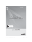
ADN✴✴✴BDE✴✴ Series
AM✴✴✴FNBD✴✴ Series
AM✴✴✴FNBF✴✴ Series
DVM Hydro unit / Hydro unit HT
installation manual
This manual is made with 100% recycled paper.
imagine the possibilities
Thank you for purchasing this Samsung product.
To receive more complete service, please
register your product at
www.samsung.com/register
EN ES FR IT PT DE EL NL PL HU RU ZH DB68-03966A(1)
k}tGokyvGo{ptWZ`]]hTXluUGGGZ
YWXZTW_TW]GGG㝘㤸G`a\Xa\X
Contents
Safety precautions . . . . . . . . . . . . . . . . . . . . . . . . . . . . . . . . . . . . . . . . . . . . . . . . . . . . . . . . . . . . . . . . . . . . . . . . . . . . . . . . . . . . . . . . . . . . . . . . . . . . . . . 2
Preparing the installation . . . . . . . . . . . . . . . . . . . . . . . . . . . . . . . . . . . . . . . . . . . . . . . . . . . . . . . . . . . . . . . . . . . . . . . . . . . . . . . . . . . . . . . . . . . . . . . . 5
Base construction and installation of the DVM Hydro unit / Hydro unit HT . . . . . . . . . . . . . . . . . . . . . . . . . . . . . . . . . . . . . . . . . . . . . . . . 8
Refrigerant pipe installation . . . . . . . . . . . . . . . . . . . . . . . . . . . . . . . . . . . . . . . . . . . . . . . . . . . . . . . . . . . . . . . . . . . . . . . . . . . . . . . . . . . . . . . . . . . . . 12
Performing leak test and insulation . . . . . . . . . . . . . . . . . . . . . . . . . . . . . . . . . . . . . . . . . . . . . . . . . . . . . . . . . . . . . . . . . . . . . . . . . . . . . . . . . . . . . 18
Installing the drain pipe . . . . . . . . . . . . . . . . . . . . . . . . . . . . . . . . . . . . . . . . . . . . . . . . . . . . . . . . . . . . . . . . . . . . . . . . . . . . . . . . . . . . . . . . . . . . . . . . . 19
Water pipe installation . . . . . . . . . . . . . . . . . . . . . . . . . . . . . . . . . . . . . . . . . . . . . . . . . . . . . . . . . . . . . . . . . . . . . . . . . . . . . . . . . . . . . . . . . . . . . . . . . . 20
Connecting power and communication cable . . . . . . . . . . . . . . . . . . . . . . . . . . . . . . . . . . . . . . . . . . . . . . . . . . . . . . . . . . . . . . . . . . . . . . . . . . . 26
Connecting external contact . . . . . . . . . . . . . . . . . . . . . . . . . . . . . . . . . . . . . . . . . . . . . . . . . . . . . . . . . . . . . . . . . . . . . . . . . . . . . . . . . . . . . . . . . . . . 36
Setting an indoor unit address and installation option . . . . . . . . . . . . . . . . . . . . . . . . . . . . . . . . . . . . . . . . . . . . . . . . . . . . . . . . . . . . . . . . . . . 50
Product maintenance . . . . . . . . . . . . . . . . . . . . . . . . . . . . . . . . . . . . . . . . . . . . . . . . . . . . . . . . . . . . . . . . . . . . . . . . . . . . . . . . . . . . . . . . . . . . . . . . . . . 58
Failure diagnosis . . . . . . . . . . . . . . . . . . . . . . . . . . . . . . . . . . . . . . . . . . . . . . . . . . . . . . . . . . . . . . . . . . . . . . . . . . . . . . . . . . . . . . . . . . . . . . . . . . . . . . . . 59
Error code . . . . . . . . . . . . . . . . . . . . . . . . . . . . . . . . . . . . . . . . . . . . . . . . . . . . . . . . . . . . . . . . . . . . . . . . . . . . . . . . . . . . . . . . . . . . . . . . . . . . . . . . . . . . . . 60
Using the PCB Switch . . . . . . . . . . . . . . . . . . . . . . . . . . . . . . . . . . . . . . . . . . . . . . . . . . . . . . . . . . . . . . . . . . . . . . . . . . . . . . . . . . . . . . . . . . . . . . . . . . . 62
Completing the installation . . . . . . . . . . . . . . . . . . . . . . . . . . . . . . . . . . . . . . . . . . . . . . . . . . . . . . . . . . . . . . . . . . . . . . . . . . . . . . . . . . . . . . . . . . . . . 63
Explaining functions to the user . . . . . . . . . . . . . . . . . . . . . . . . . . . . . . . . . . . . . . . . . . . . . . . . . . . . . . . . . . . . . . . . . . . . . . . . . . . . . . . . . . . . . . . . . 63
Appendix . . . . . . . . . . . . . . . . . . . . . . . . . . . . . . . . . . . . . . . . . . . . . . . . . . . . . . . . . . . . . . . . . . . . . . . . . . . . . . . . . . . . . . . . . . . . . . . . . . . . . . . . . . . . . . . 64
Safety precautions
Before installing an DVM Hydro unit / Hydro unit HT please read this manual thoroughly to ensure that you know how to
safely and efficiently install a new appliance.
Store the Operation and Installation in a safe location and remember to hand it over to the new owner if the Product is sold
or transferred.
❋ This product uses R-410A and R-134a(Hydro unit HT) are refrigerant.
- When using R-410A and R-134a(Hydro unit HT), moisture or foreign substances may affect the capacity and reliability
of the product. Safety precautions must be taken when installing the refrigerant pipe.
- The designed maximum pressure of the system is 4.1 MPa. Select appropriate material and thickness according to the
regulations.
- R-410A and R-134a(Hydro unit HT) are a quasi-azeotrope of two refrigerants. Make sure to charge with liquid phase
when filling refrigerant. (If you charge vapor refrigerant, it may affect the capacity and reliability of the product as a
result of a change in the blend of the refrigerant.)
❋ You must connect the outdoor unit for R-410A refrigerant. When outdoor unit for R-22 refrigerant is connected, product
cannot operate normally.)
❋ This product uses plate type heat exchanger, and extra concern must be taken regarding on selecting the installation
location since it requires water pipe installation.
❋ For product protection, closed type water circuit system must be adopted for water pipe system.
Before the installation, read the ‘Severe warning signs’ and the ‘Caution signs’ thoroughly.
Manufacturer is not responsible for accidents due to incorrect installation. (User will be responsible for any service charges
that may occur.)
Manufacturer is not responsible for any product problems that may occur due to incorrect water pipe installation.
Maintain the water temperature and the amount of water flow within operational range. Manufacturer is not responsible if
the heat exchanger freezes and ruptures due to incorrect installation.
This product has been determined to be in compliance with the Low Voltage Directive (2006/95/EC), and the Electromagnetic
Compatibility Directive (2004/108/EC) of the European Union.
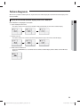
WARNING
Hazards or unsafe practices that may result in severe personal injury or death.
CAUTION
Hazards or unsafe practices that may result in minor personal injury or property damage.
2
k}tGokyvGo{ptXYWZ`]]hTXluUGGGY
YWXZTW_TW]GGG㝘㤸G`a[[aYY
SEVERE WARNING SIGNS
ENGLISH
Installation must be requested to a qualified installer.
fIf the user installs a product improperly on their own, it may cause refrigerant leakage and lead to electric shock or fire in
worst case scenario.
Install the unit in a place where it is strong enough to hold the product weight.
fWhen installed in place where it is not strong enough to withhold the product weight, the unit could fall and cause injury.
Do not put any product or object under the DVM Hydro unit / Hydro unit HT.
fWater from the DVM Hydro unit / Hydro unit HT may fall and cause fire or loss of property.
Electric work must be done by qualified persons, complying the national wiring regulations and installed according to the
instruction stated in the installation manual with leased circuit.
fCapacity shortage on the leased circuit and improper installation may cause electric shock or fire.
Use specified wires to connect the DVM Hydro unit / Hydro unit HT and outdoor unit, and make sure the wire is firmly fixed.
fImproper connection may cause fire.
Neatly arrange the wires in the electrical parts to make sure that electrical cover is closed securely without any gap.
fIf the cover is not properly closed, heat may generate on the electrical terminal and cause electric shock or fire.
Make sure to use the provided or specified parts with the specified tools for installation.
fFailing to do so may cause product failure, refrigerant leakage, fire or electric shock.
In any case of refrigerant leakage, make sure to ventilate.
fIf the refrigerant gas comes in contact with fire, harmful gas will be generated.
fMake sure that the refrigerant gas does not leak after completing the installation. If the refrigerant gas of the indoor unit
leaks and comes into contact with the fan heater, space heater or stove, harmful gas will be generated.
Make sure to perform grounding work.
fDo not connect the ground wire to a gas pipe, water pipe, lightning rod or telephone grounding. Improper grounding
could cause electric shock.
Do not install the product in a place where it is or might be exposed to inflammable gas leakage.
fWhen the gas leaks and gets accumulated around the product, it may cause fire.
Installation work must be done according to the instruction in this installation manual.
fImproper installation may cause water leakage, electric shock or fire.
When inserting the power plug, make sure to insert it fully and check that power plug and a consent does not have any dusts,
blockage or loosened part.
fIf there are dusts, blockage or loosened part on a power plug or consent, it can cause electric shock or fire. Also, replace
the consent if it is loosened.
When installation is in progress, check the following before operating the product.
fMake sure pipes are properly connected without any leakage.
fWhen there is leakage on the connected part, air may get in and cause abnormally high pressure state which may lead to
pipe explosion and personal injury.
Do not assemble the power cord on your own, use two cables together to extend the cable length or connect the power to a
multi consent connected with other products.
fBad connection, isolation and over voltage may cause fire or electric shock.
Cut-off the main power supply before electrical installation of DVM Hydro unit / Hydro unit HT.
fPotential risk or electric shock.
You may need to install an ELB (earth leakage breaker) depending on the installation location.
fNot installing an ELB (earth leakage breaker) may cause electric shock.
Supply power to the product during winter time since the product will operate in protection mode itself when the
temperature decrease below 0 °C.
fIf you cut-off the power, protection mode cannot be operated and may cause damage to the product.
fDVM Hydro unit / Hydro unit HT is designed to be installed indoor. Make sure to install it in a place where there is no risk
of surrounding temperature from dropping below zero.
3
k}tGokyvGo{ptXYWZ`]]hTXluUGGGZ
YWXZTW_TW]GGG㝘㤸G`a[[aYZ
Safety precautions
CAUTION SIGNS
Read the installation manual thoroughly before installing the product.
Make sure to transport the product with its packages on. In case if you must remove the packaging, use soft materials to carry
the product to prevent any damages on the product.
Perform the drainage/piping work securely according to the installation manual.
fIf not, water could drop from the unit and household goods could get wet and damaged.
Wear thick gloves during the installation process.
fIf not, personal injury may occur due to the air conditioner parts.
If the DVM Hydro unit / Hydro unit HT is installed in a small area, beware of oxygen deficiency in the area that may caused by
refrigerant leakage.
Do not install or operate DVM Hydro unit / Hydro unit HT in following places:
fPlace where surrounding air contains mineral oil or where oil vapor occurs; or cooking area where vapor or water
particles occur by spraying. (When particles of oil sticks to the heat exchanger following incidents may occur; it may
cause performance decrease or cause condensation water to scatter. Also, if oil particles sticks to the plastic parts, it may
cause damage or deformation of those part which may lead to product malfunction or refrigerant leakage.)
fPlace where corrosive gas, such as sulphurous gas, exists. (When installing the product in these places, contact an
installation specialty store since the copper pipe and brazing part will need additional corrosion proof or anti-rust
additive to prevent corrosion.
fPlace where product is exposed to flammable gases, carbon fiber, flammable powder/dust or place where volatile
flammable gases such as thinner or gasoline is frequently used. (Gases near DVM Hydro unit / Hydro unit HT may ignite.)
fPlace where electromagnetic waves are emitted (Control devices may not work.)
fPlace with high level of basicity within the air such as near ocean; place with high voltage fluctuation such as factory; and
within the car or ship.
fPlace where special spray is frequently used.
fPlace where fine powder is used (such as bakery)
fDo not use the product to store precision instrument, food, plants or animals, cosmetic goods, art works or any other
special purpose. (There is risk of property loss.)
fPlace where noise or vibration may occur.
After completing the installation, run the trial operation. If no error occurs, explain to the customer how to use and clean the
air conditioner according to the user’s manual. In addition give the installation manual and the user’s manual to the customer.
Before the installation, check if the product is in good shape.
fDo not install the product with the damage which occurred during shipment.
All of the materials used to manufacture product and packages are eco-friendly and they are recyclable.
Refrigerant used in this product must be added or disposed in an appropriate way by qualified personnel.
fAt the end of the life cycle, take it to a proper recycling or disposal center or return it to the dealer so that it can be
disposed correctly.
Combination rate
fThis product should be connected with indoor unit and outdoor unit of the DVM S
fThe combinations of the installation.
- This product should be combined among 50~130% of outdoor unit's capacity.
- When this product would be combined with heat pump outdoor units for 180% combination rate, it need to meet the
conditions below.
1) The combination rate for indoor units : Under the 100% of the A2A indoor units + Under the 80% of the DVM Hydro
unit/ Hydro unit HT.
2) A2A indoor units should be operated for cooling mode only, and DVM Hydro unit/ Hydro unit HT should be operated
for heating mode(including floor heating) only.
3) It is not possible to operate A2A indoor units and DVM Hydro unit/ Hydro unit HT at the same time.
4
k}tGokyvGo{ptXYWZ`]]hTXluUGGG[
YWXZTW_TW]GGG㝘㤸G`a[[aYZ
Preparing the installation
Tools required for installation
General tools
② Torque wrench
③ Pipe cutter
④ Reamer
⑤ Pipe bender
⑥ Spirit level
⑦ Screw driver
⑧ Spanner
⑨ Drill
⑩ L wrench
ENGLISH
① Vacuum pump
⑪ Measuring tape
Tools for operation
① Thermometer
② Resistance meter
③ Electroscope
Accessories (supplied)
Before the installation, make sure to check if following accessories are included inside the DVM Hydro unit / Hydro unit HT.
Installation manual
Drain plug
Drain cap
Additional accessory (not included)
Additional accessory needs to be purchased separately and installed to operate DVM Hydro unit / Hydro unit HT.
(Model name of the wire remote controller : MWR-WW00N)
Wired remote controller
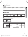
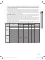
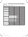
fRecommended specification of the strainer
Model type
Model name
Work pressure
Work
temperature
Water pipe
connection part
Mesh size
Material
(Strainer/Mesh)
50 Mesh
AISI316/SUS304
ADN160BDE✴✴
ADN320BDE✴✴
HE
PT 1(25A)
AM160FNBD✴✴
AM320FNBD✴✴
1.0 MPa
-5~48 °C
ADN500BDE✴✴
PT 1-1/4(32A)
AM500FNBD✴✴
HT
AM✴✴✴FNBF✴✴
-20 ~ 35 °C
PT 1(25A)
5
k}tGokyvGo{ptXYWZ`]]hTXluUGGG\
YWXZTW_TW]GGG㝘㤸G`a[[aYZ
Preparing the installation
Selecting installation location
fChoose a place with ventilation duct or opening to cool down the heat generated from the product and maintain the
surrounding temperature within Hydro unit : 5 ~ 40 °C, humidity 80 % Hydro unit HT : 5 ~ 35 °C humidity 80 %.
fChoose a place where structure can bear the weight and vibration of the DVM Hydro unit / Hydro unit HT.
fChoose a flat place that rainwater does not settle or leak.
fChoose a well ventilated place with sufficient space for repair and other services.
fChoose a place where you can easily connect the refrigerant pipes between the DVM Hydro unit / Hydro unit HT and
outdoor unit within allowable distance.
fDo not install this product in a place where it may corrode.
fInstall the power cable and communication cable of the DVM Hydro unit / Hydro unit HT and outdoor unit at least 1 m
away from the electric appliance such as TV. (In some cases, there may be problem even if there's more than 1m gap from
the electric appliances.)
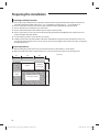
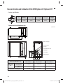
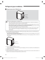
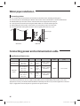
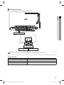
Space requirement
fWhen installing the product, make sure to secure minimum distance with obstacles as shown below.
fWhen you install one product on top of the other one, secure at least 600 mm of space on the water pipe side.
518
400
Product
Installation
space for pipe
(Unit: mm)
330
100
300
Service space (Front)
600
Service space
(Side)
6
k}tGokyvGo{ptXYWZ`]]hTXluUGGG]
YWXZTW_TW]GGG㝘㤸G`a[[aY[
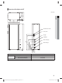
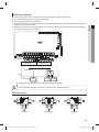
Hydro unit
(Unit: mm)
600
Service space
100
200
626
100 100
626
ENGLISH
100
400
H beam
<When installing one product on top of the other one>
600 mm
Hydro unit HT
m
0m
10
300 mm
mm
600
CAUTION
400 m
m
t If the Hydro unit / Hydro unit HT is needed to installed closed to the walls unavoidably, prevent the vibration
generated from the product to the walls with cushioning materials etc.
7
k}tGokyvGo{ptXYWZ`]]hTXluUGGG^
YWXZTW_TW]GGG㝘㤸G`a[[aY[
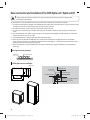
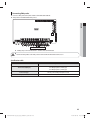
Base construction and installation of the DVM Hydro unit / Hydro unit HT
WARNING
t If this product is installed in residential area, apply anti-vibration product to prevent the vibration from
transferring to the building.
fManufacturer is not responsible for the damage occurred by not following the installation standards.
1. Considering the vibration and weight of the DVM Hydro unit / Hydro unit HT, strength of the base ground must be strong
enough to prevent noise and the top part of the base ground has to be flat.
2. Base ground should be 1.5 times larger than the bottom of the Hydro unit.
3. It is necessary to add wire mesh or steel bar during concrete construction for the base ground to prevent damages or
cracks.
4. Place the DVM Hydro unit / Hydro unit HT on the base construction and completely fix it with the bolt, nut and washer.
(The bearing force has to be over 3.5 kN)
5. Fix the DVM Hydro unit / Hydro unit HT firmly with 4 foundation bolts.
6. When concrete construction for DVM Hydro unit / Hydro unit HT installation is completed, install an anti-vibration
pad(t=20 mm or more) or an anti-vibration frame(vibration transmissibility=5 % and below) to prevent vibration of the
outdoor unit from transferring to the base ground.
7. When constructing base ground, DVM Hydro unit / Hydro unit HT must be supported within the range of following
dimensions.
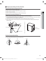
Base ground construction
Drain hole
200 mm or more
DVM Hydro unit installation
(Unit: mm)
DVM Hydro unit
365
330
333
Anchor bolt
20 mm Anti-vibration pad
Over 50 mm
340
518
16
Nut, Spring washer
A
H beam or anti-vibration frame
A+10~20 mm or more
8
k}tGokyvGo{ptXYWZ`]]hTXluUGGG_
YWXZTW_TW]GGG㝘㤸G`a[[aY\
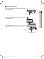
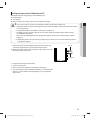
DVM Hydro unit HT installation
Considering the vibration and weight of the DVM Hydro unit HT, strength of
the base ground must be strong enough to prevent noise and the top part of
the base ground has to be flat.
ENGLISH
Level Controller
Fixed Bracket
Adjust the level controller to make fixed controller has to be min. 100 mm
higher than level controller.
100 mm
Place the DVM Hydro unit HT on the base construction and completely fix it
with the foundation bolt(M10), nut and washer.
The recommended length of foundation bolts are over 20 mm from the base
ground.
< A method of fixing the bracket >
9
k}tGokyvGo{ptXYWZ`]]hTXluUGGG`
YWXZTW_TW]GGG㝘㤸G`a[[aY\
Base construction and installation of the DVM Hydro unit / Hydro unit HT
Anchor specification
m
Diameter of
drill bit (a)
Anchor length (b)
Sleeve length (c)
Insert depth
Fastening
torque
M10
14 mm
75 mm
40 mm
50 mm
30 N·m
c
b
Size
a
Dimension of the DVM Hydro unit
365
16
340
333
330
(Unit: mm)
518
Water outlet pipe
External contact
626
Communication cable
Liquid pipe
45
45
599
Gas pipe
60
73.5 65
90
ADN160BDE✴✴
AM160FNBD✴✴
ADN320BDE✴✴
AM320FNBD✴✴
ADN500BDE✴✴
AM500FNBD✴✴
Liquid side
connection part
3/8” (ø9.52)
3/8” (ø9.52)
1/2” (ø12.7)
Gas side connection
part
5/8” (ø15.88)
7/8” (ø22.23)
1-1/8” (ø28.58)
PT 1 (25A)
PT 1 (25A)
PT 1-1/4 (32A)
Model of the DVM Hydro unit
Refrigerant
side
Water inlet pipe
100
27
205
Power cable
Water side connection part
10
k}tGokyvGo{ptXYWZ`]]hTXluUGGGXW
YWXZTW_TW]GGG㝘㤸G`a[[aY\
Dimension of the Hydro unit HT
16
340
518
ENGLISH
330
333
365
(Unit: mm)
Communication cable
Power cable
Gas pipe
Liquid pipe
772
660
Water outlet pipe
27
106
366
246
466
Water inlet pipe
73
115
Model of the Hydro unit
AM✴✴✴FNBF*B
Liquid side connection part
3/8” (ø9.52)
Gas side connection part
5/8” (ø15.88)
Refregerant side
Water side connection part
PT 1(25A)
11
k}tGokyvGo{ptXYWZ`]]hTXluUGGGXX
YWXZTW_TW]GGG㝘㤸G`a[[aY]
Refrigerant pipe installation
Refrigerant pipe work
fUse exclusive tools and accessories for R-410A to respond to pressure of the R-410A and prevent foreign substances from
entering into the pipes.
fThe length of refrigerant pipe should be as short as possible and the height difference between the DVM Hydro unit /
Hydro unit HT and outdoor unit should be minimized.
fPiping work must be done within allowable piping length, height difference, and the allowable length after branching.
fThe pressure of the R-410A is high. Use only certified refrigerant pipe and follow the installation method.
fUse clean refrigerant pipe and there shouldn’t be any harmful ion, oxide, dust, iron content or moisture inside pipe.
fPipe work must be done aside from the product.
fAfter completing the pipe installation, calculate the additional amount of refrigerant according to method of each indoor
units and make sure to use R-410A refrigerant when charging. (Color of the R-410A refrigerant container is painted in
pink.)
Model name of DVM Hydro unit
ADN160BDE✴✴
AM160FNBD✴✴
AM✴✴✴FNBF✴✴
ADN320BDE✴✴
AM320FNBD✴✴
ADN500BDE✴✴
AM500FNBD✴✴
Amount of additional refrigerant
0.6 kg
0.7 kg
1.2 kg
fDo not use Flux when welding the refrigerant pipes.
CAUTION
t In case the capacity conjunction of the Hydro Unit HT exceeds 50 % among the total indoor unit, please don’t
put the additional refrigerant.
t When operate Hydro unit HT to add R-410A refrigerant at the outdoor unit side, Hydro unit HT will not work for
cooling refrigerant charging operation if water temperature is under 33°C. Peform heating refrigerant charging
operation or perform cooling refrigerant charging operation after warming water up over 33°C.
t When operate Hydro unit HT to collect R-410A refrigerant at the outdoor unit side, Hydro unit Ht will not work if
water temperature is under 33°C. Perform refrigerant collecting operation after warming water up over 33°C.
t All other indoor units should perform the heating or stop, when R-134a refrigerant collecting operation.
Important information regulation regarding the refrigerant used
fDVM Hydro unit HT contains fluorinated greenhouse gases covered by the Kyoto Protocol.
fHermetically sealed system.
fDo not vent gases into the atmosphere.
fRefrigerant type : R-134a
fQuantity: 2.15 kg
fGlobal Warming Potential(GWP) = 1300
12
k}tGokyvGo{ptXYWZ`]]hTXluUGGGXY
YWXZTW_TW]GGG㝘㤸G`a[[aY]
Tools used for refrigerant pipe installation
Product using R-410A/R-134a refrigerant requires exclusive tools. Check the conventional tools for compatibility before
installation.
Tool
Work
Compatibility with conventional tool
Pipe cutting
Flaring tool
Pipe flaring
Compatible
Refrigerating machine
oil
Refrigerant pipe work
Apply refrigerant oil on
flared part
Use exclusive ether oil, ester oil, alkali benzene
oil or mixture of these oils
ENGLISH
Pipe cutter
Connect flare nut with
pipe
Torque wrench
Pipe bender
Pipe bending
Nitrogen gas
Compatible
Inhibition of oxidation
Air tightness test
Welder
Manifold gauge
Refrigerant charging
hose
Vacuum pump
Pipe welding
Air tightness test ~
additional refrigerant
charging
Vacuuming, charging and
checking operation
Vacuum drying
Compatible (Use products which contains the check valve to prevent the oil
from flowing backward into the outdoor unit.)
Use the one that can be vacuumed up to 100.7 kPa (5 Torr).
Need exclusive one due to the refrigerant
leakage or inflow of impurities.
Scale for refrigerant
charging
Compatible
Gas leak detector
Gas leak test
Flare nut
Need exclusive one to prevent mixture of R-22
refrigerant oil use and also the measurement is
not available due to the high pressure.
Need exclusive one
(Ones used for R-134a is compatible)
Must use the flare nut equipped with the product.
Refrigerant leakage may occur when the conventional flare nut for R-22 is used.
13
k}tGokyvGo{ptXYWZ`]]hTXluUGGGXZ
YWXZTW_TW]GGG㝘㤸G`a[[aY]
Refrigerant pipe installation
Selecting refrigerant pipe
fInstall the refrigerant pipe according to main pipe size for each capacities of DVM Hydro unit / Hydro unit HT.
ADN160BDE✴✴
AM160FNBD✴✴
AM✴✴✴FNBF✴✴
ADN320BDE✴✴
AM320FNBD✴✴
ADN500BDE✴✴
AM500FNBD✴✴
Liquid side
3/8” (ø9.52)
3/8” (ø9.52)
1/2” (ø12.7)
Gas side
5/8” (ø15.88)
7/8” (ø22.23)
1-1/8” (ø28.58)
Model name of DVM Hydro unit
Refrigerant
side
Keeping refrigerant pipe
fTo prevent foreign materials or water from entering the pipe, storing method and sealing method (especially during
installation) is very important. Apply correct sealing method depending on the environment.
fBe especially careful when you penetrate the pipe through the hole in a wall or when the end of the pipe is exposed to
outdoor during installation.
fUse the flare nut supplied with the product. If other flare nuts are used, it can cause refrigerant leakage.
Exposure place
Exposure time
Sealing type
Longer than one month
Pipe pinch
Shorter than one month
Taping
-
Taping
Outdoor
Indoor
Pinching the refrigerant pipe
fCompress the end of the refrigerant pipe and weld the compressed part.
Refrigerant pipe
Welding part
Taping the refrigerant pipe
fSeal the end of the refrigerant pipe with a PVC vinyl tape.
PVC tape
End of the pipe
Squeeze flat Stick the squeezed part to the pipe
Finish up by wrapping around the
pipe again
Refrigerant pipe
14
k}tGokyvGo{ptXYWZ`]]hTXluUGGGX[
YWXZTW_TW]GGG㝘㤸G`a[[aY]
Refrigerant pipe welding and safety information
Important information for refrigerant pipe work
ENGLISH
fMake sure there is no moisture inside the pipe.
fMake sure there are no foreign substances and impurities in the pipe.
fMake sure there is no leakage.
fMake sure to follow the instruction when welding or storing the pipe.
Nitrogen flushing welding (DVM Hydro unit)
fWhen welding the refrigerant pipes, flush them with nitrogen gas as shown in the picture.
fIf you do not perform nitrogen flushing when welding the pipes, oxide may form inside the pipe and can cause damage
to the important parts such as compressor and valves etc.
fAdjust the flow rate of the nitrogen flushing with a pressure regulator to maintain 0.05 m3/h or less.
fWhen welding the pipes on the connection port, cover the valve with wet cloth before welding (to protect the parts
within the valve)
ø6.35
Welding part
Taping
Stop valve
Nitrogen
Copper pipe (ø6.25 mm)
Pressure regulator
Wet cloth
Flowmeter
Gas side (Welded)
High pressure hose
Nitrogen
Direction of the pipe when welding
fDirection of the pipe should be headed downward or in a sideways when welding.
fAvoid welding the pipe with pipe direction heading upward.
Downward
Side
Upward
15
k}tGokyvGo{ptXYWZ`]]hTXluUGGGX\
YWXZTW_TW]GGG㝘㤸G`a[[aY]
Refrigerant pipe installation
Refrigerant pipe work on DVM Hydro unit
Wet cloth
Gas pipe
Liquid pipe
CAUTION
t Caution for welding the pipe to a DVM Hydro unit
- When welding the pipe to the product, the unit may get damaged by the heat and flame from welding. Use a
flame proofing cloth to protect the unit from a brazing fire or flame.
- Wrap the pipe with a wet cloth and weld it as shown in the illustration. Also, water dripping from the wet cloth
may interrupt the welding so make sure the water does not drip from the wet cloth.
- Make sure that connected pipes of DVM Hydro unit and the outdoor unit does not interrupt each other or make
contact with the product. (Vibration may cause damage to the pipes.)
- When removing the sealed pipe on the bottom side of the service valve, cut it with a pipe cutter first and then
start the welding. When the sealed pipe is welded without cutting, you may get injured by the refrigerant
within the pipe.
1. Remove the copper cap of the refrigerant pipe and eliminate the sludge or foreign substances on the welded part and
then weld the connecting pipe on each port.
- Since nitrogen gas is sealed within the pipe, you must discharge the nitrogen gas from the liquid pipe. Then remove the
copper cap and check for existence of the nitrogen gas.
- Check the pressure of the nitrogen gas before welding. If the nitrogen gas is not being purged, product is not normal so
do not install it.
Gas side
Copper cap
Liquid side
2. Cover the refrigerant pipe well with an insulator.
- It prevents the water, on the outer surface of the pipe, from dripping and increase the efficiency of the DVM Hydro unit.
3. Cut off the leftover insulator.
4. Check for cracks on the bent part of the pipes.
5. When the DVM Hydro unit is installed in a hot and humid place, water may form on the outer surface of the insulator so it
would be necessary to double the insulation thickness (10mm or more).
16
k}tGokyvGo{ptXYWZ`]]hTXluUGGGX]
YWXZTW_TW]GGG㝘㤸G`a[[aY]
Refrigerant pipe work on DVM Hydro unit HT
DVM Hydro unit HT has refrigerant pipes of two different types.
fLiquid side pipe
fGas side pipe
fMake sure there are no foreign substances and impurities in the pipe.
1. Remove the safety cap of the refrigerant pipe and fasten the nuts after
connecting refrigerant pipes to each port of the Hydro unit HT.
fMake sure to fasten the nut using hand of person first, after that use tools
like torque wrench and spanner.
ENGLISH
CAUTION
t There is no nitrogen gas inside of connected pipes of Hydro unit HT and the outdoor unit.
t DVM Hydro unit HT is using the new refrigerant, R-134a. The connected pipes of Hydro unit HT and the outdoor
unit are using R-410A
t The product performance or reliability can have grave consequences.
t The design pressure is 4.1 MPa, and make sure to consider selecting the refrigerant pipes which meet the
standard(material, thickness)
t Make sure to use liquid refrigerant when charging the refrigerant, because the using refrigerant is mixture
refrigerant.
❋ DVM Hydro unit HT is using heat exchanger of plate type, and make sure to consider installation location to
connecting water pipes.
Gas side
Liquid side
2.
3.
4.
5.
Wrap the refrigerant pipes with insulator.
Cut the rest of insulator.
Make sure to check any defects on the bent parts of the pipes.
The standard temperature and humidity condition is 30 °C with humidity
below 85 %. If the condition is in high humidity, use one grade thicker.
(Over 10 mm)
17
k}tGokyvGo{ptXYWZ`]]hTXluUGGGX^
YWXZTW_TW]GGG㝘㤸G`a[[aY]
Performing leak test and insulation
Before completing the installation (insulating hose and pipes), you must check for gas leakage and when there is no leakage,
you may insulate the pipes and hoses.
Leak test
Use a gas detector to check the connection part of the pipes for gas leakage.
Gas side
Gas side
Liquid side
Liquid side
Insulation
Selecting the insulator of refrigerant pipe
fInsulate the gas pipe and liquid pipe by referring to the thickness of insulator for each pipe size.
fThe standard temperature and humidity condition is 30 °C with humidity below 85 %. If the condition is in high humidity,
use one grade thicker.
Thickness of the insulator [Cooling, Heating (mm)]
Pipe
Pipe size (mm)
Standard [30 °C, 85 %]
High humidity
[30 °C, 85 % or more]
Remarks
EPDM, NBR
Liquid pipe
Gas pipe
Ø6.35~Ø9.52
9
9
Ø12.70~Ø19.05
13
13
Ø6.35
13
19
Ø9.52 ~ Ø28.58
19
25
Heat resisting
temperature should be
over 120 °C
1. To avoid condensation problems, wrap each pipes with heat-resisting
polyethylene foam.
- Make sure that the opening part of the insulation to face up.
No gap
Insulator
Heat-resisting polyethylene
foam
2. Wrap the refrigerant pipes and drain pipes with insulator.
Insulator
DVM Hydro
unit / Hydro
unit HT
Install the insulation to be
overlapped
Fix securely without any gap.
18
k}tGokyvGo{ptXYWZ`]]hTXluUGGGX_
YWXZTW_TW]GGG㝘㤸G`a[[aY^
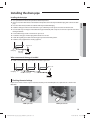
Installing the drain pipe
Installing the drain pipe
ENGLISH
fUse a spirit level to make sure that product is horizontally leveled.
fChoose one of the 2 drain holes on the bottom of the product and insert the provided drain plug, then connect the drain
pipe.
fFrom the 2 drain holes, block the unused hole with the provided rubber plug.
fInstall the drain pipe at the rear side of the unit to get a sufficient space for repairs and service on the front side.
fDo not install a trap on the pipe and install the drain pipe horizontally with a slope of 1/50 or more to prevent water from
flowing backwards.
fFor smooth drainage, install an air vent that is open to air.
fInsulate the drain pipe and drain plug with insulation over 10 mm.
fInstall self-regulating heat cable on the drain pipe to prevent it from being frozen.
fInstall the safety equipment for a heating appliance.
Open to air
Drain plug
More than
1/50 slope
When concentrated drainage is installed
fInstall a concentrated drain pipes with an air vent that is open to air.
Open to air
Drain plug
More than 1/50 slope
Checking the water leakage
Prepare about 2 liters of water and pour water into the drain pan of the DVM Hydro unit / Hydro unit HT as shown in the
illustration.
<DVM hydro unit>
<DVM hydro unit HT>
19
k}tGokyvGo{ptXYWZ`]]hTXluUGGGX`
YWXZTW_TW]GGG㝘㤸G`a[[aY^
Water pipe installation
1. You do not need to equip extra expansion tank when there's open type expansion tank on top part of the existing
thermal storage tank. However, if you do not have expansion tank, you will need to construct closed type pipe system
and equip expansion tank.
2. Water pipe installation system
1) Install the water pipe as shown in the below illustration. All the parts, other than DVM Hydro unit / Hydro unit HT,
must follow on site installation specification.
<Water pipe connection part>
Over 80 mm
Finishing tape
Water
pipe
DVM Hydro unit / Hydro unit HT
Insulator
fInstalling hot water supply
Hydro unit
On site
installation
Heat
exchanger
on water
side
①
⑭
Ball valve (Used as
cleaning hole)
Cleaning device
②③
④
⑤
⑧ Hot water tank
Water out
⑩
⑥
⑫⑪
⑦
⑨
⑬
Water in
①
Water pipe joint (union, flange)
⑤
Flexible joint
⑨
Expansion tank
②
Thermometer
⑥
Drain (within the product)
⑩
Temperature sensor for hot water tank
③
Manometer
⑦
Pump
⑪
Drain valve
④
Ball valve
⑧
Air vent
⑫
Strainer
⑬
Water Valve
⑭
Pressure relief valve (Pressure safety valve)
20
k}tGokyvGo{ptXYWZ`]]hTXluUGGGYW
YWXZTW_TW]GGG㝘㤸G`a[[aY^
fInstalling under floor heating
Hydro unit
①
⑭
Ball valve (Used as
cleaning hole)
②③
Cleaning device
④
⑤
ENGLISH
On site
installation
Heat
exchanger
on water
side
Hot water tank
⑧
Under floor
Water out heating coil
⑩
⑥
⑫⑪
⑨
⑦
⑬
Water in
①
Water pipe joint (union, flange)
⑤
Flexible joint
⑨
Expansion tank
②
Thermometer
⑥
Drain (within the product)
⑩
Temperature sensor for thermal storage tank
③
Manometer
⑦
Pump
⑪
Drain valve
④
Ball valve
⑧
Air vent
⑫
Strainer
⑬
Water Valve
⑭
Pressure relief valve (Pressure safety valve)
fOn site installation specification
Strainer
Flow meter
Thermometer
Manometer
Air vent
Pump
Ball valve Drain valve
Model name
AM160FNBF✴✴
0~50 ℓ/min
23 ℓ/min
AM250FNBF✴✴
0~100 ℓ/min
36 ℓ/min
ADN160BDE✴✴
AM160FNBD✴✴
0~50 ℓ/min
#50 PT 1
0~100 °C
ADN320BDE✴✴
AM320FNBD✴✴
0~100 ℓ/min
ADN500BDE✴✴
AM500FNBD✴✴
#50
0~150 ℓ/min
PT 1-1/4
0~100 °C
0~1 MPa
0~1 MPa
0.6 m3/h
(Condition:
0.15 MPa)
0.6 m3/h
(Condition:
0.15 MPa)
48 ℓ/min
PT 1
15 A
PT 1-1/4
15 A
92 ℓ/min
(Refer to
pressure
drop graph)
150 ℓ/min
(Refer to
pressure
drop graph)
21
k}tGokyvGo{ptXYWZ`]]hTXluUGGGYX
YWXZTW_TW]GGG㝘㤸G`a[[aY_
Water pipe installation
2) Water pipe socket must be connected with a less tightening torque value stated in the below table. If you apply more
torque, it may cause damage to the product.
Diameter of water pipe (Outer diameter, mm)
5JHIUFOJOHUPSRVF/tN
ø10~20
25
ø21~30
50
ø31~50
100
ø51~80
220
ø81~115
600
❋ /tNLHGtDN
3) Use certified parts for water pipe system and the water pressure of the water pipe system connected to outdoor unit
must remain under 1.0 MPa. Use copper or stainless pipe water pipe.
4) Water pipes must be equipped with valves and other instrumentations as shown in the diagram. Strainer and flow
switch must be installed within 1~2 m from the entrance pipe of the DVM Hydro unit / Hydro unit HT.
- When strainer is not installed, sand, dust or rust debris may cause product breakage.
5) Water inlet pipe is located at the bottom part of the heat exchanger and the water outlet pipe is at the top part of the
heat exchanger.
6) DVM Hydro unit / Hydro unit HT must be installed indoor at room temperature and the water inlet and outlet must
be insulated with the heat exchanger as shown in the diagram.
7) Damp-proof, cold reserving and insulation work must be done thoroughly to prevent condensation from forming on
the surface of the product and drain pipes of indoor/outdoor units. When the necessary work is not done thoroughly,
you will waste energy caused by thermal loss and may get property damage during cold seasons when water pipe
freezes and bursts. This product will keep the circulation pump to operation in certain interval, even when the power
is off, in order to prevent pipe rupture. Therefore, you must check if the power (220~240 V) is being supplied.
8) If you stop the product for long time or in night time, water pipe circuit may freeze naturally when the temperature
around the DVM Hydro unit / Hydro unit HT is under 0 °C. When water pipe circuit freezes, it will cause damage to the
plate type heat exchanger and therefore preventive measure must be taken according to the situation.
- Drain remaining water in the water pipe
- Install self-regulating heat cable on the water pipes
- If the product is installed in a place where surround temperature drops below 0 °C, use anti-freeze accordingly for
freezing point depression.
9) Install number of auto air discharge valve at a point where air may remain within the pipe (such as vertical water
pipe). If the air within the pipe is not discharged, it may cause performance decrease or corrosion on the product or
pipes.
10) Following is the operation range of water.
Section
Standard
condition
Cooling
Heating
Cooling
Operation range
Heating
Outlet water temperature (°C)
Amount of water (ℓ/min)
ADN✴✴✴BDE✴✴
ADN160BDE✴✴ ADN320BDE✴✴ ADN500BDE✴✴
AM✴✴✴FNBF✴✴
AM160FNBF✴✴ AM250NBF✴✴
AM✴✴✴FNBD✴✴
AM160FNBD✴✴ AM320FNBD✴✴ AM500FNBD✴✴
18
48
92
150
35
65
23
36
5~30
24~48
46~92
75~150
20~50
25~80
14~46
14~72
fWhen the amount of cooling water is out of the operation range, stop the DVM Hydro unit / Hydro unit HT and take care
of the cause before re-start the operation.
fTemperature of discharged water is very high so be careful not to come in contact with the body. Also, cover the external
water pipe with appropriate insulator for insulation and preventing burns.
22
k}tGokyvGo{ptXYWZ`]]hTXluUGGGYY
YWXZTW_TW]GGG㝘㤸G`a[[aY_
Closed circuit system
Heat source
water
Make-up water
Corrosion
Scale
Recommended
number for water
quality inspection
7.0 ~ 8.0
7.0 ~ 8.0
O
O
Twice a month
Electric conductivity [25 ˚C]
(mS/m)
30 and below
30 and below
O
O
Chloride ion (mg Cl-/L)
50 and below
50 and below
O
O
Section
Item
pH[25 ˚C]
Standard
value
24
Once a month
Sulfate ion (mg S0 /L)
50 and below
50 and below
M alkali level [pH 4.8](mg CaCo3/L)
50 and below
50 and below
O
Total hardness (mg CaCo3/L)
70 and below
70 and below
O
Calcium hardness (mg CaCo3/L)
50 and below
50 and below
O
Ionized silica (mg SiO2/L)
30 and below
30 and below
Iron (mg Fe/L)
1.0 and below
0.3 and below
O
Copper (mg Cu/L)
1.0 and below
1.0 and below
O
Not to be
detected
Not to be
detected
O
Ammonium ion (mg NH4+/L)
0.3 and below
0.1 and below
O
Residual chlorine (mg Cl/L)
0.25 and below
0.3 and below
O
Free carbon dioxide (mg CO2/L)
0.4 and below
0.4 and below
O
-
-
O
Sulfate ion(mg S2/L)
Reference
Effects
Stability index
ENGLISH
11) Water scale may occur on the plate type heat exchanger depending on the water quality and the type of plate heat
exchanger so regular chemical cleaning is necessary. When installing water pipes, install a heat source water shut-off
valve and also install the flushing pipe with a ball valves (for chemical cleaning) on the pipe installed between the
shut-off valve and the outdoor unit.
12) Before trial operation, connect the cleaning pipes installed on inlet and outlet as shown in above illustration. Then,
take appropriate measures (such as blind flange etc) to stop the circulation water from entering the outdoor unit
plate type heat exchanger, and use circulating pump to remove foreign substance within the water pipes and clean
the strainer. If you do not clean the strainer, foreign substances may accumulates on plate type heat exchanger and
may break the heat exchanger or cause problem to it.
13) Make sure that water quality within the water pipe meets the standard of cooling water quality for refrigerating and
air conditioning equipment.
- Heat source water containing high level of foreign substances can cause water heat exchanger and pipe corrosion or
creation of water scale. (Use the appropriate heat source water according to the below table)
- If the make-up water is provide from any other source than local water supply, make sure to check the quality of water.
- Strainer (which needs to be purchased separately) must be installed to the ‘Water IN’ pipes of the water pipe. If sand,
dust or rust debris enters to water system, it may cause corrosion on metallic materials or blockage of the water heat
exchanger and damage the heat exchanger.
- If the existing thermal storage tank or pipes are used, foreign substances may block the plate type heat exchanger of
the DVM Hydro unit / Hydro unit HT so, water quality and foreign substances must be managed.
O
O
Once a month
O
23
k}tGokyvGo{ptXYWZ`]]hTXluUGGGYZ
YWXZTW_TW]GGG㝘㤸G`a[[aY_
Water pipe installation
NOTE
t Circle (O) marks in the chart show the factor relevant to corrosion or water scale.
t When the water temperature is over 40˚C, steels without protective coating may corrode when expose to water.
Applying corrosion prevention material or degassing can be effective measure to prevent corrosion.
t For the cooling water and the make-up water, used under closed circuit water system with closed circuit cooling
tower, should satisfy the standard shown in above table.
t Supplied water or make-up water should be tap water, industrial water or groundwater. Purified water,
neutralized water and softened water should not be supplied.
t 15 items in the above table is a typical factor for corrosion and/or water scale.
t When water pipe circuit freezes, it will cause breakage on the plate type heat exchanger. Therefore appropriate
preventive measure must be taken according to the situation.
- Drain remaining water in the water pipe
- Constantly operate the water pump to circulate the water within the water pipe
- Install a self-regulating heat cable on the water pipe
t Open the valve of the water pipe connected to the outdoor unit after flushing (cleaning foreign substances in
water pipe) is completed.
t Check that air is vented from the water pipe and circulation amount is secured before opening the service valve
on the refrigerant side of the outdoor unit.
t When circulating water stops during outdoor nit operation, it may cause breakage on plate type heat exchanger.
24
k}tGokyvGo{ptXYWZ`]]hTXluUGGGY[
YWXZTW_TW]GGG㝘㤸G`a[[aY_
Pressure drop graphs
fADN160BDE✴✴ / AM160FNBD✴✴
fADN320BDE✴✴ / AM320FNBD✴✴
Pressure drop from heat
exchanger (kPa)
ENGLISH
Pressure drop from heat
exchanger (kPa)
Water flow rate (ℓ/min)
fADN500BDE✴✴ / AM500FNBD✴✴
fAM✴✴✴FNBF✴✴
Pressure drop from heat
exchanger (kPa)
Pressure drop from heat
exchanger (kPa)
Water flow rate (ℓ/min)
Water flow rate (ℓ/min)
Water flow rate (ℓ/min)
25
k}tGokyvGo{ptXYWZ`]]hTXluUGGGY\
YWXZTW_TW]GGG㝘㤸G`a[[aY_
Water pipe installation
Connecting strainer
fUse a strainer with 50 mesh (Diameter of each hole must be under 0.4 mm, excluding punching plate)
fConnect the strainer after checking the direction of the strainer on the water inlet hole as shown in the illustration.
fWind the Teflon tape more than 15 times on the thread of the water pipe before connecting it.
fService port must face downward and angle should be within 45° on the left and the right side.
fAfter installing the strainer, makes sure that there is no water leakage on the connection part.
fFor normal operation of the product, clean the strainer regularly (more than once a year).
Water inlet pipe
Strainer
45°
<Front view>
<Side view>
Connecting power and communication cable
Specification of electric wires
Indoor unit
DVM Hydro unit
DVM Hydro
unit HT
Power supply
MCCB [A]
ELB [A]
Power cable (mm2)
X [A]
X [A],
30 mA,
0.1 sec 2.5 mm2 (Single
Installation)
X [A]
X [A],
30 mA,
0.1 sec 4.0 mm2 (Single
Installation)
X [A]
X [A],
30 mA,
0.1 sec 2.5 mm2 (Single
Installation)
1Ø, 220 V/50 Hz
Max : 242 V
Min : 198 V
1Ø,
220~240 V/50 Hz
Max : 264 V
Min : 198V
3Ø,
380~415 V/50 Hz
Max : 456.5 V
Min : 342 V
Earth cable
(mm2)
Communication cable
(mm2)
2.5 mm2
0.75~1.5 mm2
This Equipment complies with IEC 61000-3-12, provided that the short-circuit power Ssc is greater than or equal to 3.881 M
at the interface point between the user's supply and the public system. It is responsibility of the installer or user of the
equipment to ensure, by consultation with the distribution network operator if necessary that the equipment is connected
only to a supply with a short-circuit power Ssc greater than or equal to 3.881 M
26
k}tGokyvGo{ptXYWZ`]]hTXluUGGGY]
YWXZTW_TW]GGG㝘㤸G`a[[aY_
❋ Table for current (Single installation)
Indoor unit
DVM Hydro unit
DVM Hydro unit HT
Rated current (A)
MCA ( A)
MFA( A)
0.05
2.2
2.75
14.3
23.1
4.85
7.85
24.15
32.15
12.88
12.88
30.19
40.19
16.1
16.1
ENGLISH
Model
ADN✴✴✴BDE✴✴
AM✴✴✴FNBD✴✴
AM160FNBFE✴
AM250FNBFE✴
AM160FNBFG✴
AM250FNBFG✴
fELB, MCCB capacity expression
X [A] = 1.25 X ∑Ai
❋ X [A] : ELB, MCCB capacity
❋ ∑Ai : Sum of each indoor unit's rated current
❋ Refer to each installation manual about the rating current of indoor unit.
fDecide the power cable specification and maximum length within 10 % power drop among indoor units.
Coef×35.6×Lk×ik
n
∑(
k=1
) < 10 % of input voltage[V]
1000×Ak
t coef : 1.55
t Lk : Distance among each indoor unit [m], Ak : Power cable specification [mm2]
ik : Running current of each unit [A]
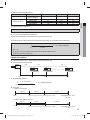
Example of Installation
fTotal power cable length L = 100(m), Running current of each units 1[A]
fTotal 10 indoor units were installed
10[A]
MCCB+
ELCB ELB
9[A]
1[A]
Or
Indoor unit 1
0[m]
10[m]
Indoor unit 10
Indoor unit 2
20[m]
100[m]
fApply following equation
n
∑(
k=1
Coef×35.6×Lk×ik
) < 10 % of input voltage[V]
1000×Ak
❋ Calculation
t Installing 1 type of wire.
2.5[mm2]
2.5[mm2]
-2.2[V]
-2.0[V]
220[V]
············ 2.5[mm2] ············
-(2.2+2.0+1.8+1.5+1.3+1.1+0.9+0.7+0.4+0.2)=-11.2[V]
208.8[V](Within 198 V~242 V)
it's okay
t Installing with 2 different sort wire.
4.0[mm2]
-1.4[V]
220[V]
4.0[mm2]
············ 2.5[mm2] ············
-1.2[V]
-(1.4+1.2+1.8+1.5+1.3+1.1+0.9+0.7+0.4+0.2)=-10.5[V]
209.5[V](Within 198 V~242 V)
it's okay
27
k}tGokyvGo{ptXYWZ`]]hTXluUGGGY^
YWXZTW_TW]GGG㝘㤸G`a[[aY`
Connecting power and communication cable
Overall system configuration
DVM Hydro unit / Hydro unit HT use 220~240 V or three phase, 380~415 V(DVM Hydro unit HT)
Distribution board
Outdoor unit
Indoor unit
ELCB
or
ELCB +
ELB
3 Phase
1 Phase
ELCB
or
ELCB +
ELB
Earth
ELCB
or
ELCB +
ELB
Communication cable
DVM Hydro
unit / Hydro
unit HT
Exclusive
wired remote
controller
CAUTION
Earth
Wired remote
controller
Wired remote
controller
Wired remote
controller
t Do not divide communication cable multiple times from one indoor/DVM Hydro unit / Hydro unit HT to another.
It may cause communication error.
t Do not divide power cable multiple times from one Hydro unit HT to another. DVM Hydro unit HT can get a
damage.
28
k}tGokyvGo{ptXYWZ`]]hTXluUGGGY_
YWXZTW_TW]GGG㝘㤸G`a[[aY`
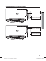
Power supply and communication cable configuration
Main PCB
ENGLISH
fWithdraw a main power cable and a grounding cable through the cable outlet on the right side of the DVM Hydro unit /
Hydro unit HT.
fWhen connecting external contact signal wire, connect them to the PCB terminal board through the cable outlets in the
right side of the outdoor unit.
fWires must be installed after putting them in separate cable protection tubes.
fFix a cable tube at the cable outlet using a CD connector.
Power cable terminal board
Wired remote controller wiring
Power cable (Fix it to the clamp on
the bottom of the terminal board)
%7.)ZESPVOJUt0VUEPPSVOJU
communication cable
Conduit
Cable protection tube
Main PCB
Control kit
Power cable Terminal board
Wired remote controller wiring
DVM Hydro unit HT+Outdoor unit
Communication cable
Conduit
Cable protection tube
29
k}tGokyvGo{ptXYWZ`]]hTXluUGGGY`
YWXZTW_TW]GGG㝘㤸G`a[[aZW
Connecting power and communication cable
Specifications of the cable protection tube
Name
Material
Applicable conditions
Flexible PVC
conduit
PVC
When the cable tube is installed indoor and not exposed to outside, because it is
embedded in concrete structure
Class 1 flexible
conduit
Galvanized steel sheet
When the cable tube is installed indoor but exposed to outside so there are risk
of damage to the cable tube
Class 1 PVC coated
flexible conduit
Galvanized steel sheet
and Soft PVC compound
When the cable tube is installed outdoor and exposed to outside so there are risk
of damage to the cable tube and extra waterproof is needed
Power and communication wiring diagram
ELCB
or
ELCB +
ELB
Indoor and outdoor unit
communication
R
S
T
N
Earth
Earth
Communication cable
between indoor and
outdoor units
PBA
DVM Hydro unit / Hydro unit HT
fThe communication cable between indoor and outdoor units has no polarity.
fArrange the cables using a clamp attached on the left side of the terminal board.
fWhen you connect the power cable, you must apply rated tightening torque to connect the screws for the terminal board
(L-N).
30
k}tGokyvGo{ptXYWZ`]]hTXluUGGGZW
YWXZTW_TW]GGG㝘㤸G`a[[aZW
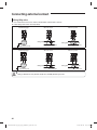
PBA connection diagram
fADN160BDE✴✴
Wired remote
controller
ENGLISH
V2
V1
Outdoor unit
(Communication cable)
L
N
Power cable (1 Phase AC
220~240 V)
fAM✴✴✴FNBD✴✴
V2
Wired remote
controller
V1
Outdoor unit
(Communication cable)
L
N
Power cable (1 Phase AC
220~240 V)
31
k}tGokyvGo{ptXYWZ`]]hTXluUGGGZX
YWXZTW_TW]GGG㝘㤸G`a[[aZX
Connecting power and communication cable
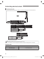
fAM✴✴✴FNBF✴✴
DVM Hydro unit /
Hydro unit HT
L
N
1(L) 2(N)
L
DVM Hydro unit /
Hydro unit HT
R
1(L)
N
cable tie
Power cable 1 phase AC Communication cable
220~240V
N
2(N) L1(R) L2(S) L3(T)
F1 F2 V1 V2 F3 F4
- Three phase
F1 F2 V1 V2 F3 F4
- Single phase
N
cable tie
Power cable 1 phase AC Communication cable
220~240V
32
k}tGokyvGo{ptXYWZ`]]hTXluUGGGZY
YWXZTW_TW]GGG㝘㤸G`a[[aZY
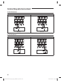
Wiring diagram for connecting 2 wired remote controllers
fADN✴✴✴BDE✴✴
Wired remote controller (slave)
V1
ENGLISH
V2
Wired remote controller (master)
L
N
fAM✴✴✴FNBD✴✴ / AM✴✴✴FNBD✴✴
V2
Wired remote controller (slave)
V1
Wired remote controller (master)
L
N
33
k}tGokyvGo{ptXYWZ`]]hTXluUGGGZZ
YWXZTW_TW]GGG㝘㤸G`a[[aZZ
Connecting power and communication cable
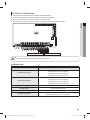
Connecting the power terminal
F1 F2
fConnect the cables to the terminal board using a solderless ring terminal.
fProperly connect the cables by using certified and rated cables and make sure to fix them properly so that external force
is not applied to the terminal.
fUse a driver and wrench that can apply the rated torque when tightening the screws on the terminal board.
fTighten the terminal screws by complying rated torque value. If the terminal is loose, arc heat may occur and cause fire
and if the terminal is connected too firmly, terminal may get damaged.
L N
Solderless terminal
Power cable
Connect one cable per terminal
and fix it with a solderless terminal.
Terminal name
Tightening Torque (N·m)
External contact
M3
0.5~0.6
Communication
M3.5
0.8~1.0
Power
M4
1.2~1.5
<DVM Hydro unit >
L
N
1(L) 2(N)
L
N
<DVM Hydro unit HT>
34
k}tGokyvGo{ptXYWZ`]]hTXluUGGGZ[
YWXZTW_TW]GGG㝘㤸G`a[[aZZ
Selecting solderless ring terminal
fSelect a solderless ring terminal for a power cable according to the
nominal dimensions for cable.
fApply insulation coating to the connection part of the solderless ring
terminal and the power cable.
Silver solder
ENGLISH
Nominal dimensions for cable (mm2)
Nominal dimensions for screw (mm)
Standard dimension (mm)
1.5
2.5
4
5
6.6
8
4
6.6
8.5
10
16
5
5
5
9.5
12
12
B
Allowance (mm)
±0.2
±0.2
±0.2
±0.2
Standard dimension (mm)
3.4
4.2
7.1
9
Allowance (mm)
+0.3
-0.2
+0.3
-0.2
+0.3
-0.2
+0.3
-0.2
Standard dimension (mm)
1.7
2.3
4.5
5.8
Allowance (mm)
±0.2
±0.2
±0.2
±0.2
E
Min.
4.1
6
7.9
9.5
F
Min.
6
9.5
L
Max.
24
30
5.3
5.3
+ 0.2
0
+ 0.2
0
+ 0.2
0
0.8
1.15
1.45
D
d1
7
5.3
Allowance (mm)
+ 0.2
0
+ 0.2
0
0.7
7
17.5
4.3
Min.
6
16
Standard dimension (mm)
d2
t
6
4.3
5.3
35
k}tGokyvGo{ptXYWZ`]]hTXluUGGGZ\
YWXZTW_TW]GGG㝘㤸G`a[[aZZ
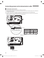
Connecting external contact
External contact connection diagram
Wired remote controller
V2
V1
Outdoor unit (communication
cable)
Ⓠ
Water IN/OUT (Hydro unit HT)
L
N
Water IN/OUT (Hydro unit)
L
N
EVA IN/OUT (Hydro unit / Hydro
unit HT)
Flow switch
Defrost
Ⓐ
Main power
Ⓑ
Operation check
Ⓒ
Alarm
AC 24 V Thermostat
Ⓓ
Water pump
AC 230 V Thermostat
Ⓔ
Booster heater
2Way valve
Ⓗ
Ⓕ
3Way valve 1
3Way valve 2
Ⓖ
1
Connected as factory default
Ⓘ
2
3
Ⓙ Indoor temperature
4
5
6
7
8
9 10 11 12 13 14 15 16 17 18 19 20
Ⓚ Temperature sensor
sensor
Ⓛ
Ⓝ
Solar pump
Smart grid
for water tank
Ⓜ
External control
<DVM Hydro unit>
1
2
Ⓙ Indoor temperature
3
4
5
Ⓛ
6
7
8
Solar pump
9 10
Ⓜ
External control
Ⓝ
Smart grid
sensor
Ⓚ Temperature sensor
for water tank
<DVM Hydro unit HT>
36
k}tGokyvGo{ptXYWZ`]]hTXluUGGGZ]
YWXZTW_TW]GGG㝘㤸G`a[[aZ[
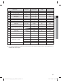
Explanation
Terminal No.
Input / Output
AC/DC
Maximum
allowable current
Power
L, N
Input
AC
2.5 A
B
Operation check
B1, B2
Contact output
-
0.5 A
C
Alarm
B3, B4
Contact output
-
0.5 A
D
Water pump
B5, B6
Contact output
-
0.5 A
E
Booster heater
B7, B8
Contact output
-
0.5 A
F
3Way valve 1
B9 ~ B11
Output
AC
0.5 A
G
3Way valve 2
B12 ~ B14
Output
AC
0.5 A
H
2Way valve
B15 ~ B17
Output
AC
0.5 A
I
AC 230, AC 24 V Thermostat
B19 ~ B26
Input
AC
0.5 A
J
Indoor temperature sensor
1,2(1,2)
Input
DC
1 mA
K
Temperature sensor for water tank
7,8(3,4)
Input
DC
20 mA
L
Solar pump
13,14(5,6)
Input
AC
10 mA
M
External control
16,17(7,8)
Input
DC
1 mA
N
Smart grid
19,20(9,10)
Input
DC
1 mA
O
Communication cable (RS485)
F1, F2
Input , Output
DC
10 mA
V1
Output
DC
210 mA (per each
controller)
V2
Grounding
-
-
F3, F4
Input, Output
DC
10 mA
F/S
Input
DC
1 mA
P
Q
Wired remote controller
Flow switch
ENGLISH
A
❋ ( ) : Hydro unit HT
❋ For instruction regarding on wiring power, communication and wired remote controller, refer to "Connecting power and
communication cable" chapter.
37
k}tGokyvGo{ptXYWZ`]]hTXluUGGGZ^
YWXZTW_TW]GGG㝘㤸G`a[[aZ[
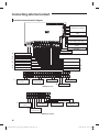
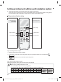
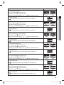
Connecting external contact
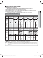
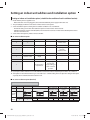
fRefer to the below table for the terminal numbers that needs on the site for connecting external contact.
Terminal No.
External contact
Operation status / inspection checklist
Remarks
B1, B2
Operation check
B3, B4
Alarm
B5, B6
Water pump
B7, B8
Booster heater
Check the status of the heater operation signal output at the
control panel on the site
Optional
B9~B11
3Way valve 1
Check the status of signal output and on/off status of valve
operation (Direction switch of the indoor hot water tank)
Optional
B12~B14
3Way valve 2
Check the status of signal output and on/off status of valve
operation (interlocked with solar pump signal)
Optional
B15~B17
2Way valve
Check the status of signal output or operation status of the valve
Optional
B19, B20
AC230, Thermostat 1
Check the connection status of the thermostat and operation
status of the product (cooling)
Optional
B21, B22
AC230, Thermostat 2
Check the connection status of the thermostat and operation
status of the product (heating)
Optional
B23, B24
AC24, Thermostat 1
Check the connection status of the thermostat and operation
status of the product (cooling)
Optional
B25, B26
AC24, Thermostat 2
Check the connection status of the thermostat and operation
status of the product (heating)
Optional
1, 2 (1, 2)
Indoor temperature
sensor
Check the temperature display on the wired remote controller
after separately installing the indoor temperature sensor (Refer to
option setting of the wired remote controller)
Optional
7, 8 (3, 4)
Temperature sensor for
water tank
13, 14 (5, 6)
Solar pump
Check the solar pump contact signal input and status of the
operation
Optional
16, 17 (7, 8)
External control
Check the contact signal input and status of the operation
Optional
19, 20 (9, 10)
Smart grid
Check the Smart Grid contact input and the signal
Optional
Check on/off status for operation lamp of the control panel on
the site
Optional
Check on/off status for alert lamp of the panel on the site
Optional
Check the status of the pump operation signal and on/off status
of operation at the control panel on the site
Check the temperature display on the wired remote controller
after installing the 4~20mA temperature sensor
Mandatory
Mandatory
(hot water supply
operation)
❋ ( ) : Hydro unit HT
38
k}tGokyvGo{ptXYWZ`]]hTXluUGGGZ_
YWXZTW_TW]GGG㝘㤸G`a[[aZ[
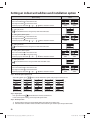
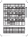
Water pump connection
fConnect a water pump to B5, B6 of the PBA terminal block.
ENGLISH
V2
V1
L
N
Water pump
Relay
PCB
Terminal board
B5
B6
Controller
Pump
Power
t Terminal of this product is for water pump and the maximum allowable current is 0.5 A
CAUTION
Specification table
Part
Specification
Terminal block (Output)
B5, B6
Connection type
Water pump (No-voltage contact)
39
k}tGokyvGo{ptXYWZ`]]hTXluUGGGZ`
YWXZTW_TW]GGG㝘㤸G`a[[aZ\
Connecting external contact
Booster heater connection
fConnect a booster heater to B7, B8 of the PBA terminal block.
V2
V1
L
N
Booster heater
Relay
PCB
Terminal board
B7
B8
Controller
Booster heater
Power
Specification table
Part
Specification
Terminal block (Output)
B7, B8
Connection type
Booster heater (No-voltage contact)
40
k}tGokyvGo{ptXYWZ`]]hTXluUGGG[W
YWXZTW_TW]GGG㝘㤸G`a[[aZ\
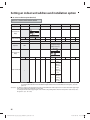
3Way valve connection
ENGLISH
fCheck the type of 3Way valve and connect it to the terminal board as shown in the illustration.
fUse a rated wire and connect it as shown in the illustration.
fInitial setting of the valve is 'closed (no flow)'.
f3Way valve 1: Change the water flow direction to the indoor and hot water tank. (Direction will be towards indoor when
Normal open type valve is installed)
f3Way valve 2: Change the water flow direction to the solar energy and hot water tank. (Direction will be towards indoor
when Normal open type valve is installed)
V2
V1
L
N
3Way valve 1
3Way valve 2
L
N
Relay
PCB
Terminal block
B9/B12
B10/B13
B11/B14
❋ Initially, relay is connected between L and B11/B14 of the terminal block.
t Before completing installation of 3Way valve, check the opening direction of the port.
CAUTION
Allowed connection
A
B
A
B
A
B
AB
AB
AB
Allowed (O)
Not allowed (X)
Allowed (O)
41
k}tGokyvGo{ptXYWZ`]]hTXluUGGG[X
YWXZTW_TW]GGG㝘㤸G`a[[aZ]
Connecting external contact
Example of installation (Danfoss H-series valve)
fConnecting the valve
Brown
Blue
Brown
Blue
L
N
L
N
3-port diverter valves
A
B
A
B
AB
AB
Brown
Blue
Grey
3-port mid-position valves
A
Brown
Blue
L
N
L
Grey
B
A
L
N
L
B
AB
AB
fExample of wiring
Brown
Blue
Brown
B10
Blue
B9
B11
B9
3-port diverter valves
DHW
A
B
A
AB
B
DHW
AB
Brown
Blue
Brown
B10
Blue
B9
Grey
B11
B9
Grey
3-port mid-position valves
DHW
A
B
AB
A
B
DHW
AB
42
k}tGokyvGo{ptXYWZ`]]hTXluUGGG[Y
YWXZTW_TW]GGG㝘㤸G`a[[aZ^
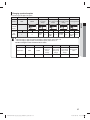
Connecting 2Way valve
fConnect a 2Way valve to B15, B16 and B17 of the PBA terminal block.
f2Way valve is interlocked with 3Way valve 1.
ENGLISH
V2
V1
L
N
2Way valve
❋ Initially, relay is connected between L and B17 of the terminal block.
t Terminal of this product is for 2Way valve and the maximum allowable current is 0.5 A
CAUTION
Specification table
Part
Specification
Terminal block (Output)
B15: Output power N
B16: Output power L (switch type)
B17: Output power L (switch type)
Connection type
Directly connect 2Way valve (below 0.5 A)
Output (B15~B17)
AC 230 V (Max 0.5 A / 120 W)
43
k}tGokyvGo{ptXYWZ`]]hTXluUGGG[Z
YWXZTW_TW]GGG㝘㤸G`a[[aZ^
Connecting external contact
Wiring 2Way valve
fUse a rated wire to connect it as shown in the illustration and fix it with a cable tie.
fInitial setting of the valve is 'closed (no flow)'.
Normal close type
2Way
valve (N/C
type)
When it is closed
Mixing tank
2Way valve
Normal open type
*N/O (Normal open)
DHW
Mixing tank
*N/C (Normal closed)
2Way
valve (N/O
type)
When it is opened
2Way valve
When it is closed
Mixing tank
DHW
DHW
When it is opened
Mixing tank
2Way valve
DHW
2Way valve
t Wiring is different for a N/C (Normal closed) valve and N/O (Normal open) valve.
CAUTION
44
k}tGokyvGo{ptXYWZ`]]hTXluUGGG[[
YWXZTW_TW]GGG㝘㤸G`a[[aZ_
AC 230V or AC 24V thermostat
fConnect the indoor thermostat to B19~B26 of the PBA terminal block.
fConnect a thermostat to the designated terminal as stated in the rated table.
fOnly 1 type of thermostat can be connected. (B19~B22 or B23~B26)
fProduct will not operate when signal for cooling and heating mode is inputted at the same time.
ENGLISH
V2
V1
L
N
AC 230 V Thermostat
AC 24 V Thermostat
t Maximum allowable current of each terminal is below 10mA
CAUTION
Specification table
Part
Specification
Terminal block (AC 230V)
B19: Output power L (for cooling mode)
B20: Input power N (for cooling mode)
B21: Output power L (for heating mode)
B22: Input power N (for heating mode)
Terminal block (AC 24V)
B23: Output power L (for cooling mode)
B24: Input power N (for cooling mode)
B25: Output power L (for heating mode)
B26: Input power N (for heating mode)
Connection type
Connect to indoor power controller
Input (B19~B22)
AC 230 V (Maximum 10 mA)
Input (B23~B26)
AC 24 V (Maximum 10 mA)
Condition for operation
When B20 or B24 is detected -> cooing mode
When B22 or B26 is detected -> heating mode
45
k}tGokyvGo{ptXYWZ`]]hTXluUGGG[\
YWXZTW_TW]GGG㝘㤸G`a[[aZ_
Connecting external contact
AC 230 V thermostat
Cooling mode
Heating mode
N
N
L
L
Thermostat
Thermostat
Cooling mode
Heating mode
AC 24 V thermostat
N
L
Thermostat
N
L
Thermostat
46
k}tGokyvGo{ptXYWZ`]]hTXluUGGG[]
YWXZTW_TW]GGG㝘㤸G`a[[aZ`
Connecting temperature sensor of water tank and flow switch
fConnect the temperature sensor of water tank to number 7 and 8 of the terminal block located on the bottom side.
fConnect 4~20mA temperature sensor for water tank. Temperature sensor must be connected to water tank for hot water
operation.
ENGLISH
V2
V1
Flow switch
L
N
1
2
3
4
5
6
7
8
9 10 11 12 13 14 15 16 17 18 19 20
Temperature sensor of water tank (4~20 mA
sensor: Temperature range - 0~100 ˚C)
<DVM Hydro unit>
1
2
3
4
5
6
7
8
9 10
Temperature sensor of water tank (4~20 mA
sensor: Temperature range - 0~100 ˚C)
<DVM Hydro unit HT>
47
k}tGokyvGo{ptXYWZ`]]hTXluUGGG[^
YWXZTW_TW]GGG㝘㤸G`a[[a[W
Connecting external contact
Connecting solar pump
fConnect the signal wire for solar pump to number 13 and 14 of the terminal block located on the bottom side.
V2
V1
L
N
1
2
3
4
5
6
7
8
9 10 11 12 13 14 15 16 17 18 19 20
Solar pump
Controller
Power
<DVM Hydro unit>
1
2
3
4
5
6
7
8
9 10
Solar pump
Controller
Power
<DVM Hydro unit HT>
CAUTION
t Maximum allowable current of each terminal is below 10 mA.
t Ports number 13 and 14 is for input port for detection and they do not supply power to a solar pump.
Specification table
Part
Specification
Terminal block (Input)
13, 14: No-voltage contact
Connection type
Connect to solar pump controller (contact signal)
48
k}tGokyvGo{ptXYWZ`]]hTXluUGGG[_
YWXZTW_TW]GGG㝘㤸G`a[[a[W
Grounding work
A ground rod must be installed if the grounding terminal on the power circuit does not exist or meet the standard. Additional
accessories required for installation must be purchased separately since they are not supplied with DVM Hydro unit / Hydro
unit HT.
1. Prepare a ground rod that matches the one shown in the illustration.
Copper wire
ENGLISH
Carbon rod or Copper rod
Solderless terminal (for M4 screw)
Green or yellow wire insulated with PVC, 2 mm2 x 3.5 m
2. Select a appropriate place to install a ground rod.
- It is better to select a damp and firm ground than sandy ground or ground with gravels which is high-resisting.
- Avoid place with underground structure or facilities. (Gas pipe, water pipe, phone lines, or underground cable)
- Place has to be at least 2 m away from the lightening rod.
❋ Ground wire for phone lines cannot be used for grounding DVM Hydro unit / Hydro unit HT.
3. Install a green or yellow ground wire.
- Refer to the illustration on step 1 for the specification of a ground rod.
- If the ground wire is too short, it can be extended but connected part (where extended wire is connected) must be
wrapped with insulation tape. (Do not bury the connected part underground.)
- Fix the ground wire.
❋ Ground wire must be fixed firmly when it is installed at a place with lots of passerby.
30 cm
50 cm
4. Check the ground resistance with a earth resistance tester to see if installation is done properly.
- If the resistance value exceeds requirement, place the ground rod deeper or add more ground rods.
5. Connect the ground wire to the terminal block of DVM Hydro unit / Hydro unit HT.
49
k}tGokyvGo{ptXYWZ`]]hTXluUGGG[`
YWXZTW_TW]GGG㝘㤸G`a[[a[W
Setting an indoor unit address and installation option
fSet the indoor unit address and installation option with remote controller option.
Set the each option separately since you cannot set the ADDRESS setting and indoor unit installation setting option at
the same time.You need to set twice when setting indoor unit address and installation option.
The procedure of option setting
Entering mode for
option setting
Option setting mode
Mode change
High Temp Button
High Fan Button
Low Temp Button
Low Fan Button
Step 1. Entering mode to set option
1. Remove batteries from the remote controller.
2. Insert batteries and enter the option setting mode while pressing High Temp button and Low Temp button.
3.
Check if you have entered the option setting status.
Step 2. The procedure of option setting
After entering the option setting status, select the option as listed below.
CAUTION
Option setting is available from SEG1 to SEG 24
t SEG1, SEG7, SEG13, SEG19 are not set as page option.
t Set the SEG2~SEG6, SEG8~SEG12 as ON status and SEG14~18, SEG20~24 as OFF status.
SEG1 SEG2 SEG3 SEG4 SEG5 SEG6 SEG7 SEG8 SEG9 SEG10 SEG11 SEG12
0
X
X
X
X
X
1
X
X
X
X
X
SEG13 SEG14 SEG15 SEG16 SEG17 SEG18 SEG19 SEG20 SEG21 SEG22 SEG23 SEG24
2
X
X
X
X
X
3
X
X
X
X
X
On(SEG1~12) Off(SEG13~24)
50
k}tGokyvGo{ptXYWZ`]]hTXluUGGG\W
YWXZTW_TW]GGG㝘㤸G`a[[a[X
Option setting
1. Setting SEG2, SEG3 option
Press Low Fan button( ) to enter SEG2 value.
Press High Fan button( ) to enter SEG3 value.
Each time you press the button, p p … p will be selected in rotation.
Status
SEG3
SEG4
SEG5
SEG6
SEG8
SEG9
SEG10
SEG11
SEG12
SEG14
SEG15
ENGLISH
SEG2
2. Setting Cool mode
Press Mode button to be changed to Cool mode in the ON status.
3. Setting SEG4, SEG5 option
Press Low Fan button( ) to enter SEG4 value.
Press High Fan button( ) to enter SEG5 value.
Each time you press the button, p p … p will be selected in rotation.
4. Setting Dry mode
Press Mode button to be changed to DRY mode in the ON status.
5. Setting SEG6, SEG8 option
Press Low Fan button( ) to enter SEG6 value.
Press High Fan button( ) to enter SEG8 value.
Each time you press the button, p p … p will be selected in rotation.
6. Setting Fan mode
Press Mode button to be changed to FAN mode in the ON status.
7. Setting SEG9, SEG10 option
Press Low Fan button( ) to enter SEG9 value.
Press High Fan button( ) to enter SEG10 value.
Each time you press the button, p p … p will be selected in rotation.
8. Setting Heat mode
Press Mode button to be changed to HEAT mode in the ON status.
9. Setting SEG11, SEG12 option
Press Low Fan button( ) to enter SEG11 value.
Press High Fan button( ) to enter SEG12 value.
Each time you press the button, p p … p will be selected in rotation.
10. Setting Auto mode
Press Mode button to be changed to AUTO mode in the OFF status.
11. Setting SEG14, SEG15 option
Press Low Fan button( ) to enter SEG14 value.
Press High Fan button( ) to enter SEG15 value.
Each time you press the button, p p … p will be selected in rotation.
12. Setting Cool mode
Press Mode button to be change to Cool mode in the OFF status.
51
k}tGokyvGo{ptXYWZ`]]hTXluUGGG\X
YWXZTW_TW]GGG㝘㤸G`a[[a[[
Setting an indoor unit address and installation option
Option setting
Status
13. Setting SEG16, SEG17 option
Press Low Fan button( ) to enter SEG16 value.
Press High Fan button( ) to enter SEG17 value.
Each time you press the button, p p … p will be selected in rotation.
SEG16
SEG17
SEG18
SEG19
SEG21
SEG22
SEG23
SEG24
14. Setting Dry mode
Press Mode button to be change to Dry mode in the OFF status.
15. Setting SEG18, SEG20 option
Press Low Fan button( ) to enter SEG18 value.
Press High Fan button( ) to enter SEG20 value.
Each time you press the button, p p … p will be selected in rotation.
16. Setting Fan mode
Press Mode button to be change to Fan mode in the OFF status.
17. Setting SEG21, SEG22 option
Press Low Fan button( ) to enter SEG21 value.
Press High Fan button( ) to enter SEG22 value.
Each time you press the button, p p … p will be selected in rotation.
18. Setting Heat mode
Press Mode button to be change to HEAT mode in the OFF status.
19. Setting SEG23, SEG24 mode
Press Low Fan button( ) to enter SEG23 value.
Press High Fan button( ) to enter SEG24 value.
Each time you press the button, p p … p will be selected in rotation.
Step 3. Check the option you have set
After setting option, press
button to check whether the option code you input is correct or not.
p
p
p
p
p
p
p
p
p
Step 4. Input option
Press operation button
with the direction of remote control for set.
For the correct option setting, you must input the option twice.
Step 5. Check operation
1) Reset the indoor unit by pressing the RESET button of indoor unit or outdoor unit.
2) Take the batteries out of the remote controller and insert them again and then press the operation button.
52
k}tGokyvGo{ptXYWZ`]]hTXluUGGG\Y
YWXZTW_TW]GGG㝘㤸G`a[[a[^
Setting an indoor unit address (MAIN/RMC)
ENGLISH
1. Check whether power is supplied or not.
- When the indoor unit is not plugged in, there should be additional power supply in the indoor unit.
2. The panel(display) should be connected to an indoor unit to receive option.
3. Before installing the indoor unit, assign an address to the indoor unit according to the air conditioning system plan.
4. Assign an indoor unit address by wireless remote controller.
- The initial setting status of indoor unit ADDRESS(MAIN/RMC) is “0A0000-100000-200000-300000”.
Option No. : 0AXXXX-1XXXXX-2XXXXX-3XXXXX
Option
Explanation
SEG1
PAGE
SEG2
SEG3
MODE
Setting Main
address
SEG4
SEG5
SEG6
100-digit of indoor 10-digit of indoor The unit digit of an
unit address
unit
indoor unit
Remote
Controller
Display
Indication Details Indication Details Indication Details Indication Details Indication Details Indication Details
0
A
Option
SEG7
SEG8
Explanation
No Main
address
Main
address
1
setting
mode
SEG9
0
Indication
and
Details
PAGE
Setting RMC
address
0~9
100-digit
SEG10
0~9
10-digit
0~9
A unit
digit
SEG11
SEG12
Group
channel(*16)
Group address
Remote
Controller
Display
Indication Details Indication Details Indication Details Indication Details Indication Details Indication Details
Indication
and
Details
0
1
1
CAUTION
No RMC
address
RMC
address
setting
mode
RMC1
0~2
RMC2
0~F
t When “A”~”F” is entered to SEG5~6, the indoor unit MAIN ADDRESS is not changed.
t If you set the SEG 3 as 0, the indoor unit will maintain the previous MAIN ADDRESS even if you input the option
value of SEG5~6.
t If you set the SEG 9 as 0, the indoor unit will maintain previous RMC ADDRESS even if you input the option value
of SEG11~12.
53
k}tGokyvGo{ptXYWZ`]]hTXluUGGG\Z
YWXZTW_TW]GGG㝘㤸G`a[[a[_
Setting an indoor unit address and installation option
Setting an indoor unit installation option (suitable for the condition of each installation location)
1. Check whether power is supplied or not.
- When the indoor unit is not plugged in, there should be additional power supply in the indoor unit.
2. The panel(display) should be connected to an indoor unit to receive option.
3. Set the installation option according to the installation condition of an air conditioner.
- The default setting of an indoor unit installation option is “020000-100000-200010-300000
- Individual control of a remote controller(SEG20) is the function that controls an indoor unit individually when there is
more than one indoor unit.
4. Set the indoor unit option by wireless remote controller.
■ 02 series installation option
SEG1
SEG2
SEG3
SEG4
SEG5
SEG6
0
2
-
-
Central control
-
SEG7
SEG8
SEG9
SEG10
SEG11
SEG12
1
-
-
-
Opening the
electronic
expansion valve
-
SEG13
SEG14
SEG15
SEG16
SEG17
SEG18
2
External control
External control
output
-
-
-
SEG19
SEG20
SEG21
SEG22
SEG23
SEG24
Heating setting
compensation
EEV opening of
an indoor unit
stopped during oil
return or Defrost
operation.
-
-
3
-
fIf you input a number other than 0~4 of the individual control of the indoor unit(SEG20), the indoor is set as “indoor 1”.
fSEG5 option for centralized control usage is set to 0(disuse) as a default setting. You must adjust the setting for this option
separately when centralized control needs to be used.
■ 02 series installation option(Detailed)
Option No. : 0AXXXX-1XXXXX-2XXXXX-3XXXXX
Option
SEG1
SEG2
SEG3
Explanation
PAGE
MODE
Use of robot cleaning
SEG4
Use of external
temperature sensor
SEG5
Use of central
control
SEG6
FAN RPM
compensation
Remote
Controller
Display
Indication
and Details
Indication Details Indication Details Indication
0
0
2
Details
Disuse
Indication Details Indication
0
Disuse
0
1
Details
Disuse
Use
Indication Details
0
Disuse
54
k}tGokyvGo{ptXYWZ`]]hTXluUGGG\[
YWXZTW_TW]GGG㝘㤸G`a[[a[_
Option
SEG7
SEG8
SEG9
SEG10
Explanation
PAGE
Use of drain
pump
Use of hot water heater
Use of electronic
heater
SEG11
Opening the electronic
expansion valve of an
indoor unit when heating
operation stops.
SEG12
Master / Slave
Indication Details Indication Details Indication
0
Disuse
0
Indication
and
Details
Details
Disuse
Indication Details Indication
0
Disuse
0
1
Option
SEG13
Explanation
PAGE
SEG14
SEG15
Use of external Setting the output of external
control
control
SEG16
S-Plasma ion
Details Indication Details
Default
0
slave
Noise
1
reduction
setting
SEG17
SEG18
Number of hours
Buzzer control
using filter
ENGLISH
Remote
Controller
Display
Remote
Controller
Display
Indication Details Indication Details Indication
Details
0
Disuse
0
Thermo on
Indication
ON/OFF
1
and
2
Control
1
Operation on
Details
OFF
2
Control
Option
SEG19
SEG20
SEG21
Explanation
PAGE
Individual control of a
remote controller
Heating setting
compensation
Indication Details Indication
0
Disuse
0
SEG22
EEV opening of an indoor
unit stopped during oil
return or defrost operation.
Details
Disuse
-
Indication Details
0
500 Hour
-
-
-
SEG23
SEG24
-
Human sensor
Remote
Controller
Display
Indication
and
Details
Indication Details Indication Details Indication
0
0
1
2
3
-
-
-
-
3
4
5
Details
Indication
Default
0
2 °C
5 °C
Default + Heating
condensation control
1
2 °C + Heating condensation
discharge control
5 °C + Heating condensation
discharge control
Details Indication
Default
0
Details
-
Indication Details
0
-
Noise
reduction
setting
■ 05 series installation option
SEG1
SEG2
SEG3
SEG4
SEG5
SEG6
0
5
-
-
-
-
SEG7
SEG8
SEG9
SEG10
SEG11
SEG12
1
-
-
Compensation option for Long
pipe or height difference between
indoor units
-
-
SEG13
SEG14
SEG15
SEG16
SEG17
SEG18
2
-
-
-
-
-
SEG19
SEG20
SEG21
SEG22
SEG23
SEG24
3
-
-
-
-
-
55
k}tGokyvGo{ptXYWZ`]]hTXluUGGG\\
YWXZTW_TW]GGG㝘㤸G`a[[a\W
Setting an indoor unit address and installation option
■ 05 series installation option(Detailed)
Option No. : 05XXXX-1XXXXX-2XXXXX-3XXXXX
Option
SEG1
SEG2
Explanation
PAGE
MODE
SEG3
SEG4
SEG5
SEG6
SEG10
SEG11
SEG12
Remote Controller
Display
Indication and Details
Option
Explanation
Indication Details
Indication
Details
0
5
SEG7
SEG8
PAGE
SEG9
Compensation option
for Long pipe or height
diffference between
indoor units
Remote Controller
Display
Indication Details
Indication
0
1
Indication and Details
1
2
Details
Use default
value
1) Height
difference1)
is more than
30m or
2) Distance2)
is longer than
110m
1) Height
difference is1)
15~30m or
2) Distance2) is
50~110m
1) Height difference : The difference of the height between the corresponding indoor uint and the indoor unit installed at the lowest place.
For example, When the indoor unit is installed 40m higher than the indoor unit installed at the lowest place, select the
option "1".
2) Distance : The difference between the pipe length of the indoor unit installed at the farthest place from an outdoor unit and the pipe length
of the corresponding indoor unit from an outdoor unit.
For example, when the farthest pipe length is 100m and the corresponding indoor unit is 40m away from an outdoor unit, select
the option "2". (100 - 40 = 60m)
56
k}tGokyvGo{ptXYWZ`]]hTXluUGGG\]
YWXZTW_TW]GGG㝘㤸G`a[[a\Y
Changing a particular option
You can change each digit of set option.
Option
SEG1
SEG2
Explanation
PAGE
MODE
Remote
Controller
Display
Indication
and
Details
NOTE
ENGLISH
SEG3
SEG4
SEG5
SEG6
The option mode The tens’ digit of an The unit digit of an
you want to
option SEG you will option SEG you will The changed value
change
change
change
Indication Details Indication Details Indication Details Indication Details Indication Details Indication Details
Tens’
The
Option
Unit digit
0
D
0~F
digit of
0~9
0~9 changed 0~9
mode
of SEG
SEG
value
t When changing a digit of an indoor unit address setting option, set the SEG3 as ‘A’.
t When changing a digit of indoor unit installation option, set the SEG3 as ‘2’.
Ex) When setting the ‘buzzer control’ into disuse status.
Option
SEG1
SEG2
SEG3
SEG4
SEG5
SEG6
The tens’ digit
of an option
SEG you will
change
The unit digit
of an option
SEG you will
change
The changed
value
1
7
1
Explanation
PAGE
MODE
The option
mode you
want to
change
Indication
0
D
2
57
k}tGokyvGo{ptXYWZ`]]hTXluUGGG\^
YWXZTW_TW]GGG㝘㤸G`a[[a\Y
Product maintenance
1. Water quality management
- Plate type heat exchanger is designed in a impossible way to disassemble part for cleaning or replace the parts. To
prevent corrosion or water scale on the plate type heat exchanger, you must manage the cooling water quality in
compliance with national standards.
- If the temperature of water is higher than room temperature, make sure to keep the concentration of chloride ion
below 100 ppm to prevent corrosion and the water hardness should be below 150 mCaCO3/L to prevent water scale.
When scale inhibitor is used, make sure to use the ones that does not cause corrosion to stainless steel and copper.
2. Amount of water flow management
- Insufficient amount of water flow will lead to accidents related to frozen plate type heat exchanger. Check to make sure
if there is any decrease in amount of water flow due to blocked strainer, problem on air ventilation or circulation pump
after checking the temperature/pressure difference between the inlet and outlet of the plate type heat exchanger. If
the temperature/pressure difference exceeds optimal range, stop the operation until cause is taken care before re-start
the operation.
3. Precautions on plate type heat exchanger maintenance
fMake sure to tell the user to keep this installation manual.
1) When the product was not operated for long period of time, check the followings.
- Check the water to see if the water quality meets the standard.
- Clean the strainer.
- Check to see if there is enough amount of water flow. (Flow switch must work at minimum amount of water flow.)
- Check to see if there is any problems on the water pressure, amount of water and the water temperature at inlet/outlet.
2) Plate type heat exchanger is designed in a impossible way to disassemble part for cleaning. Therefore it has to be
cleaned by following methods.
- Check if there is any cleaning hole for chemical cleaning at the inlet water pipe. For water scale cleaning use diluted
(down to 5 %) citric acid, oxalic acid, acetic acid, phosphoric acid. However, do not use a cleaning solution containing
hydrochloric acid, sulfuric acid or nitric acid since they are highly corrosive.
- Check if there is valve on the inlet/outlet of the plate type heat exchanger.
- Connect a exclusive pipe for cleaning to the inlet/outlet pipe of the plate type heat exchanger and fill the detergent
at the temperature of 50~60˚C and circulate the detergent for about 2~5 hours. Cleaning time can be different
depending on the temperature of detergent or degree of water scale. Judge the degree of water scale removal by the
color of water detergent.
- After cleaning, discharge the detergent within the plate type heat exchanger and fill the plate type heat exchanger
with a water mixed with 1~2 % of sodium hydroxide (NaOH) or sodium bicarbonate (NAHCO3). Circulate the water
mixture for 15~20 minutes to neutralize.
- After neutralizing the pipes, rinse the plate type heat exchanger with distilled water.
- If you are using the detergent sold at local retail stores, make sure that it doesn't cause any corrosion to the stainless
steel.
- For detail information on cleaning method (and proper use of detergent), contact the detergent manufacturer.
3) After cleaning, check to see if it is possible to operate normally.
58
k}tGokyvGo{ptXYWZ`]]hTXluUGGG\_
YWXZTW_TW]GGG㝘㤸G`a[[a\Y
Failure diagnosis
When there is problem on DVM Hydro unit / Hydro unit HT, error will be displayed on the Main PCB and the display of the
remote controller.
ENGLISH
Display on the remote controller display when error is detected
Error indications are displayed as seen below.
1. Hydro unit/Hydro unit HT error
- The address of Error, “Ai” and the error code will be displayed alternately on the remote controller display.
2. Outdoor unit error
- The address of Error, “Ao” and error code will be displayed alternately on the remote controller display.
3. Wired remote controller error
- The error code will blink at 0.5 second interval on the remote controller display and the address of error will not be
displayed.
59
k}tGokyvGo{ptXYWZ`]]hTXluUGGG\`
YWXZTW_TW]GGG㝘㤸G`a[[a\Y
Error code
Please follow below instruction when there is error on sensor.
fCheck the resistance of the sensor
- Hydro unit : Water pipe inlet/outlet, R-410A EVA IN/OUT 10 kΩ @ 25 °C
- Hydro unit HT : Water pipe inlet/outlet 200 kΩ @25 °C, R-410A EVA IN/OUT 10 kΩ @25 °C
fCheck the DVM Hydro unit / Hydro unit HT's system diagram for the location of each sensor.
fCheck if the sensor is attached properly to the copper pipe.
fIf the problem persist after checking following above instruction, replace the PBA.
CAUTION
t When error is occurred due to 'Freeze prevention', 'Pipe rupture protection' (E907, E908/E909), make sure to solve
the cause before re-start the operation.
Display
Explanation
Communication error between DVM Hydro unit / Hydro unit HT and outdoor unit
(When DVM Hydro unit / Hydro unit HT is having trouble with receiving data from outdoor unit)
Communication error on outdoor unit
(When outdoor unit is having trouble sending data to DVM Hydro unit / Hydro unit HT)
Communication error between DVM Hydro unit / Hydro unit HT and Control Kit (Detection from the Control Kit)
Error on room temperature sensor of DVM Hydro unit / Hydro unit HT (Short or Open)
Error on EVA IN sensor of DVM Hydro unit / Hydro unit HT (Short or Open)
Error on EVA OUT sensor of DVM Hydro unit / Hydro unit HT (Short or Open)
EVA IN sensor of DVM Hydro unit / Hydro unit HT is detached
EVA OUT sensor of DVM Hydro unit / Hydro unit HT is detached
EVA IN and EVA OUT sensor of DVM Hydro unit / Hydro unit HT is detached
Error due to opened EEV of DVM Hydro unit / Hydro unit HT (2nd detection)
Error due to closed EEV of DVM Hydro unit / Hydro unit HT (2nd detection)
Mixed operation mode error
EEPROM error
EEPROM option setting error
Check the water circulating
Cross wiring error (When power line is connected to communication line of DVM Hydro unit / Hydro unit HT)
Error due to disconnected Thermal Fuse (When the temperature of terminal block is increases)
Communication error between remote controller and the DVM Hydro unit / Hydro unit HT
Communication error between master and slave remote controller
Tracking error between remote controller and the DVM Hydro unit / Hydro unit HT
Error due to exceeding maximum numbers of Hydro unit installation (16 units)
Error due to exceeding maximum numbers of wired remote controller installation (2 units)
Error caused by installing mixed models
Remote controller's temperature sensor is disconnected or has problem
Data error on remote controller (Memory read/write error)
60
k}tGokyvGo{ptXYWZ`]]hTXluUGGG]W
YWXZTW_TW]GGG㝘㤸G`a[[a\Z
Display
Explanation
Error on the sensor of water inlet pipe (Short or Open)
Error on the sensor of water outlet pipe (Short or Open)
Error on water tank (Short or open)
Error due to pipe rupture protection
ENGLISH
Error due to freeze prevention(Re-operation is possible)
Error due to freeze prevention(Re-operation is impossible)
Water temperature sensor on water outlet pipe is detached
Flow switch off error, When the switch is turned off within 10 seconds after a pump starts its operation(Reoperation is possible)
Six times detection for Flow Switch Error(Re-operation is not possible)
Error due to incorrect thermostat connection
Error on DC fan(Non-operating)
System diagram for DVM Hydro unit / Hydro unit HT
Temperature sensor for
Water outlet pipe
Temperature sensor for
refrigerant gas pipe
Refrigerant gas pipe
Water out
Strainer
S
Check valve
Refrigerant liquid pipe
Strainer
Flow switch
Solenoid valve
Temperature sensor for
Water inlet pipe
Temperature sensor
for refrigerant
liquid pipe
Water in
<DVM Hydro unit>
location of the sensor
Connector 25.4 mm
Pinch pipe
Charging port
Pinch pipe
LOW Press.
Sensor
Charging port
4-Way V/V
High Press. Sensor
Compressor
Connector 25.4 mm
Filter
R-410A Cycle
Filter
R-134a Cycle
Water Cycle
<DVM Hydro unit HT>
61
k}tGokyvGo{ptXYWZ`]]hTXluUGGG]X
YWXZTW_TW]GGG㝘㤸G`a[[a\[
Using the PCB Switch
Switch is located on the main PCB.
1. Check the power between DVM Hydro unit / Hydro unit HT and the distribution board.
- Single phase: L, N
- Three phase: R, S, T, N
2. Check the outdoor unit.
1) Check if power and communication cable of the outdoor unit is connected properly. (Communication cable between
the DVM Hydro unit / Hydro unit HT and the outdoor unit should be connected to F1, F2)
2) Check the connection of the temperature sensor, drain pump and display etc.
3. Press the [K1] button to check the information on status of DVM Hydro unit / Hydro unit HT as shown in the below table.
[K1] Number of press
Display
Displayed contents
SEG1
SEG2
SEG3
SEG4
1
Capacity of DVM Hydro unit / Hydro unit HT
1
25000W 250
2
Set temperature
2
27 °C 027
3
Current temperature
3
27 °C 027
4
Room temperature
4
27 °C 027
5
EVA IN temperature
5
-17 °C -17
6
EVA OUT temperature
6
-17 °C -17
7
WATER IN temperature
7
-17 °C -17
8
WATER OUT temperature
8
-17 °C -17
9
Hot water tank temperature
9
27 °C 027
10
Defrost bypass valve
A
ON 000 / OFF 001
11
Pump output
B
ON 000 / OFF 001
12
Flow switch input
C
ON 001 / OFF 000
13
EEV Step
D
1400 140
14
Current targeted degree of super heat
E
3 °C 003
15
DVM Hydro unit / Hydro unit HT address
F
01 001
16
Version
2012/10/29 CA29
4. When there are more than one error, press the [K2] button to check the errors.
[K2] Number of press
Displayed contents
1
Currently displayed error
2
Most recently occurred error 1
3
Most recently occurred error 2
62
k}tGokyvGo{ptXYWZ`]]hTXluUGGG]Y
YWXZTW_TW]GGG㝘㤸G`a[[a\\
Completing the installation
fMeasure the power terminal (1 phase : L, N) and the grounding of the outdoor unit using a DC 500 V insulation resistance
meter before connecting the power.
The measured value should be over 30 MΩ
ENGLISH
CAUTION
t Never measure the communication terminal to prevent the communication circuit from being damaged.
t Check the short-circuit of the communication terminal using a general circuit tester.
t When you execute Key operation (trial operation, pump down etc.) from the outdoor unit, select 'Water
temperature' as a control type for DVM Hydro unit / Hydro unit HT. (This can be set from the service mode for
wired remote controller)
Explaining functions to the user
When the DVM Hydro unit / Hydro unit HT is completed explain the following functions to the user by referring to the user
manual.
1.
2.
3.
4.
Starting/Stopping the operation of DVM Hydro unit / Hydro unit HT.
Adjusting the temperature when selecting the operation mode.
Setting the 'On/Off timer'
Cleaning the DVM Hydro unit / Hydro unit HT.
- To prevent performance decrease or product failure, strainer on the DVM Hydro unit / Hydro unit HT must be cleaned
regularly (at least once a year). Explain these matters to the user and how to clean the strainer.
5. When user moves out for long time, user should drain water circuit of the product, or do not cut off the power supply if
the outside temperature is under the 0 °C
CAUTION
t Hand over the user manual to the user after explaining the functions of the DVM Hydro unit / Hydro unit HT and
make sure to tell them to keep the manual.
63
k}tGokyvGo{ptXYWZ`]]hTXluUGGG]Z
YWXZTW_TW]GGG㝘㤸G`a[[a\\
Appendix
Model specification (weight and dimension)
Type
DVM Hydro unit
Hydro unit HT
Outdoor unit (DVM S HP)
Outdoor unit (DVM S HR)
Outdoor unit (DVM ECO)
Model
Net weight
Net dimension (W x D x H)
AM160FNBDEH/EU
29.0 kg
518 x 330 x 627 mm
AM320FNBDEH/EU
33.0 kg
518 x 330 x 627 mm
AM500FNBDEH/EU
40.0 kg
518 x 330 x 627 mm
AM160FNBFEB/EU
104 kg
518 x 330 x 1,210 mm
AM160FNBFGB/EU
105 kg
518 x 330 x 1,210 mm
AM250FNBFEB/EU
104 kg
518 x 330 x 1,210 mm
AM250FNBFGB/EU
105 kg
518 x 330 x 1,210 mm
AM080FXVAGH
190 kg
880 x 765 x 1,695
AM100FXVAGH
190 kg
880 x 765 x 1,695
AM120FXVAGH
190 kg
880 x 765 x 1,695
AM140FXVAGH
235 kg
1,295 x 765 x 1,695
AM160FXVAGH
278 kg
1,295 x 765 x 1,695
AM180FXVAGH
300 kg
1,295 x 765 x 1,695
AM200FXVAGH
300 kg
1,295 x 765 x 1,695
AM220FXVAGH
300 kg
1,295 x 765 x 1,695
AM080FXVAGR
195 kg
880 x 765 x 1,695
AM100FXVAGR
195 kg
880 x 765 x 1,695
AM120FXVAGR
195 kg
880 x 765 x 1,695
AM140FXVAGR
241 kg
1,295 x 765 x 1,695
AM160FXVAGR
284 kg
1,295 x 765 x 1,695
AM180FXVAGR
306 kg
1,295 x 765 x 1,695
AM200FXVAGR
306 kg
1,295 x 765 x 1,695
AM220FXVAGR
306 kg
1,295 x 765 x 1,695
AM040FXMDEH
100 kg
940 x 330 x 1,210
AM050FXMDEH
100 kg
940 x 330 x 1,210
AM060FXMDEH
103 kg
940 x 330 x 1,210
AM040FXMDGH
100 kg
940 x 330 x 1,210
AM050FXMDGH
100 kg
940 x 330 x 1,210
AM060FXMDGH
103 kg
940 x 330 x 1,210
64
k}tGokyvGo{ptXYWZ`]]hTXluUGGG][
YWXZTW_TW]GGG㝘㤸G`a[[a\\
Memo
ENGLISH
65
k}tGokyvGo{ptXYWZ`]]hTXluUGGG]\
YWXZTW_TW]GGG㝘㤸G`a[[a\\