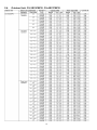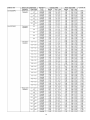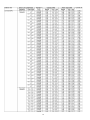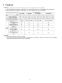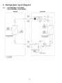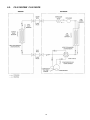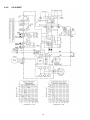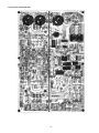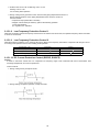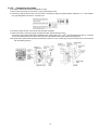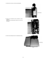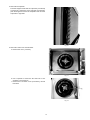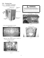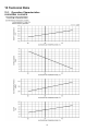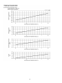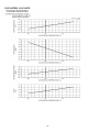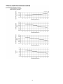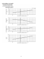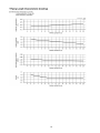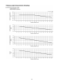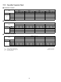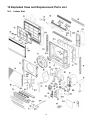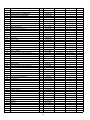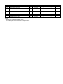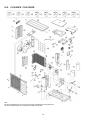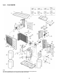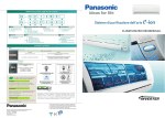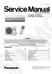
1
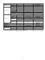
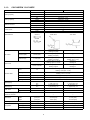
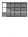
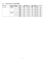
Order No. RAC0704001C2
Air Conditioner
CS-E9GFEW CU-E9GFE
CS-E12GFEW CU-E12GFE
CS-E18GFEW CU-E18GFE
Please file and use this manual together with the Service Manual for Model No. CU-2E15GBE, Order No. MAC0704001A2, Model
No. CU-3E18EBE, Order No. RAC0602011C2, Model No. CU-3E23CBPG, CU-4E27CBPG, Order No.RAC0209005C2.
TABLE OF CONTENTS
PAGE
1 Safety Precautions----------------------------------------------- 2
2 Specifications ----------------------------------------------------- 4
2.1. Floor Type --------------------------------------------------- 4
2.2. Outdoor Unit: CU-2E15GBE ---------------------------10
2.3. Outdoor Unit: 3E18EBE--------------------------------- 11
2.4. Outdoor Unit: CU-3E23CBPG
CU4E27CBPG-------------------------------------------------12
3 Features ------------------------------------------------------------16
3.1. Remote Control -------------------------------------------17
3.2. Indoor Unit--------------------------------------------------18
PAGE
3.3. Outdoor Unit----------------------------------------------- 19
4 Location of Controls and Components------------------ 20
4.1. Indoor Unit ------------------------------------------------- 20
4.2. Outdoor Unit----------------------------------------------- 20
4.3. Remote Control------------------------------------------- 20
5 Dimensions ------------------------------------------------------- 21
5.1. Indoor Unit ------------------------------------------------- 21
5.2. Outdoor Unit----------------------------------------------- 22
6 Refrigeration Cycle Diagram -------------------------------- 24
© 2007 Panasonic HA Air-Conditioning (M) Sdn. Bhd.
(11969-T). All rights reserved. Unauthorized copying
and distribution is a violation of law.
6.1. CS-E9GFEW CU-E9GFECS-E12GFEW CUE12GFE ---------------------------------------------------- 24
6.2. CS-E18GFEW CU-E18GFE -------------------------- 25
7 Wiring Connection Diagram --------------------------------- 26
7.1. Indoor Unit ------------------------------------------------- 26
7.2. Outdoor Unit ----------------------------------------------- 27
8 Electronic Circuit Diagram----------------------------------- 29
8.1. Indoor Unit / Remote Controller ---------------------- 29
8.2. Outdoor Unit ----------------------------------------------- 31
9 Operation and Control----------------------------------------- 34
9.1. Simultaneous Operation Control (Multi Type
Only)--------------------------------------------------------- 34
9.2. Basic Function -------------------------------------------- 35
9.3. Room Temperature Control (Compressor
Control) ----------------------------------------------------- 36
9.4. Automatic Operation------------------------------------- 37
9.5. Indoor Fan Motor Operation --------------------------- 39
9.6. Airflow Direction Control-------------------------------- 41
9.7. Powerful Mode Operation ------------------------------ 44
9.8. ON Timer Control ---------------------------------------- 44
9.9. OFF Timer Control --------------------------------------- 44
9.10. Auto Restart Control------------------------------------- 45
9.11. Indication Panel------------------------------------------- 45
10
11
12
13
14
9.12. Auto Operation Switch --------------------------------9.13. Freeze Prevention Control ---------------------------9.14. Dew Prevention Control-------------------------------9.15. Protection Control Features--------------------------Self Diagnosis Display---------------------------------------10.1. Self Diagnosis Function -------------------------------10.2. Error Codes Table --------------------------------------Installation Instruction---------------------------------------11.1. Auto switch operation----------------------------------11.2. Changing the remote control transmission
code --------------------------------------------------------11.3. Indoor Unit------------------------------------------------11.4. Outdoor Unit ---------------------------------------------Disassembly and Assembly Instructions -------------12.1. Indoor Unit------------------------------------------------12.2. Outdoor Unit ---------------------------------------------Technical Data --------------------------------------------------13.1. Operation Characteristics ----------------------------13.2. Sensible Capacity Chart ------------------------------Exploded View and Replacement Parts List----------14.1. Indoor Unit------------------------------------------------14.2. CU-E9GFE CU-E12GFE-----------------------------14.3. CU-E18GFE-----------------------------------------------
45
45
46
46
53
53
54
56
56
56
57
65
68
68
72
74
74
86
87
87
90
92
1 Safety Precautions
• Read the following “SAFETY PRECAUTIONS” carefully before perform any servicing.
• Electrical work must be installed or serviced by a licensed electrician. Be sure to use the correct rating of the power plug and
main circuit for the model installed.
• The caution items stated here must be followed because these important contents are related to safety. The meaning of each
indication used is as below.
Incorrect installation or servicing due to ignoring of the instruction will cause harm or damage, and the seriousness is classified
by the following indications.
This indication shows the possibility of causing death or serious injury.
This indication shows the possibility of causing injury or damage to properties.
The items to be followed are classified by the symbols:
This symbol denotes item that is PROHIBITED from doing.
• Carry out test running to confirm that no abnormality occurs after the servicing. Then, explain to user the operation, care and
maintenance as stated in instructions. Please remind the customer to keep the operating instructions for future reference.
1.
Engage dealer or specialist for installation and servicing. If installation or servicing done by the user is defective, it will cause water leakage,
electrical shock or fire.
2.
Install according to this installation instructions strictly. If installation is defective, it will cause water leakage, electrical shock or fire.
3.
Use the attached accessories parts and specified parts for installation and servicing. Otherwise, it will cause the set to fall, water leakage,
fire or electrical shock.
4.
Install at a strong and firm location which is able to withstand the set's weight. If the strength is not enough or installation is not properly
done, the set will drop and cause injury.
2
5.
For electrical work, follow the local national wiring standard, regulation and the installation instruction. An independent circuit and single
outlet must be used. If electrical circuit capacity is not enough or defect found in electrical work, it will cause electrical shock or fire.
6.
Use the specified cable and connect tightly for indoor/outdoor connection. Connect tightly and clamp the cable so that no external force will
be acted on the terminal. If connection or fixing is not perfect, it will cause heat-up or fire at the connection.
7.
Wire routing must be properly arranged so that control board cover is fixed properly. If control board cover is not fixed perfectly, it will cause
heat-up at connection point of terminal, fire or electrical shock.
8.
When connecting the piping, do not allow air or any substances other than the specified refrigerant to enter the refrigeration
cycle. Otherwise, this may lower the capacity, cause abnormally high pressure in the refrigeration cycle, and possibly result in
explosion and injury.
9.
Thickness of copper pipes used must be more than 0.8 mm. Never use copper pipes thinner than 0.8 mm.
10. It is desirable that the amount of residual oil is less than 40 mg/10 m.
11. Do not modify the length of the power supply cord or use of the extension cord, and do not share the single outlet with other
electrical appliances. Otherwise, it will cause fire or electrical shock.
1.
The equipment must be earthed. It may cause electrical shock if grounding is not perfect.
2.
Do not install the unit at place where leakage of flammable gas may occur. In case gas leaks and accumulates at surrounding
of the unit, it may cause fire.
3.
Carry out drainage piping as mentioned in installation instructions. If drainage is not perfect, water may enter the room and damage the
furniture.
4.
Pb free solder has a higher melting point than standard solder; typically the melting point is 50 - 70°F (30 - 40°C) higher. Please use a high
temperature soldering iron. In case of the soldering iron with temperature control, please set it to 700 ± 20°F (370 ± 10°C).
Pb free solder will tend to splash when heated too high (about 1100°F/600°C).
1.
Selection of the installation location. Select an installation location which is rigid and strong enough to support or hold the unit, and select a
location for easy maintenance.
2.
Power supply connection to the conditioner. Connect the power supply cord of the air conditioner to the mains using one of the following
methods. Power supply point shall be the place where there is ease for access for the power disconnection in case of emergency.
In some countries, permanent connection of this room air conditioner to the power supply is prohibited.
1. Power supply connection to the receptacle using a power plug. Use an approved power plug with earth pin for the connection to the
socket.
2. Power supply connection to a circuit breaker for the permanent connection. Use an approved circuit breaker for the permanent
connection. It must be a double pole switch with a minimum 3.5 mm contact gap.
3.
Do not release refrigerant during piping work for installation, servicing reinstallation and during repairing a refrigeration parts. Take care of
the liquid refrigerant, it may cause frostbite.
4.
Installation work. It may need two people to carry out the installation work.
5.
Do not install this appliance in a laundry room or other location where water may drip from the ceiling, etc.
3
2 Specifications
2.1.
Floor Type
2.1.1.
CS-E9GFEW CU-E9GFE
ITEM
UNIT
CS-E9GFEW
CU-E9GFE
kW
Cooling Capacity
Heating Capacity
Moisture Removal
Power Source
Airflow Method
2.50 (0.80 ~ 3.00)
kCal/h
2,150 (690 ~ 2,580)
BTU/h
8,500 (2,700 ~ 10,200)
kW
3.60 (0.80 ~ 5.00)
kCal/h
3,100 (690 ~ 4,300)
BTU/h
12,300 (2,700 ~ 17,100)
l/h
1.4
pt/h
(2.9)
Phase
Single
V
220 / 230 / 240
Cycle
50
OUTLET
SIDE VIEW
TOP VIEW
INTAKE
Air Volume
Indoor Air (Lo)
m3/min (cfm)
Indoor Air (Me)
m3/min (cfm)
Indoor Air (Hi)
m3/min (cfm)
Cooling; 5.6 (198)
Cooling; 7.4 (261)
Noise Level
Power Level dB
Electrical Data
W
Running Current
A
—
Heating; 7.6 (268)
dB (A)
Input
—
Heating; 5.6 (198)
Cooling; 9.3 (328)
Cooling; 29.8 (1,050)
Heating; 9.6 (339)
Heating; 29.8 (1,050)
Cooling; High 38, Low 27
Cooling; 46
Heating; High 38, Low 28
Heating; 47
Cooling; High 54
Cooling; 59
Heating; High 54
Heating; 60
Cooling; 570 (175 - 780)
Heating; 865 (165 - 1,360)
Cooling; 2.75 / 2.70 / 2.65
Heating; 4.20 / 4.05 / 3.90
EER
W/W(kcal/hw), BTU/hw
Cooling; 4.39 (3.78), 15.0
COP
W/W(kcal/hw), BTU/hw
Heating; 4.16 (3.58), 14.2
Starting Current
A
4.20
Piping Connection Port
(Flare piping)
inch
G; Half Union 3/8"
G; 3-way valve 3/8"
inch
L; Half Union 1/4"
L; 2-way valve 1/4"
Piping Size
(Flare piping)
inch
G; (gas side); 3/8"
G; (gas side); 3/8"
Drain Hose
inch
L; (liquid side); 1/4"
L; (liquid side); 1/4"
Inner diameter
mm
15
—
Length
mm
220
—
—
—
Power Cord Length
Number of core-wire
Dimensions
Net Weight
—
—
Height
(inch) mm
23-5/8 (600)
21-1/4 (540)
Width
(inch) mm
27-9/16 (700)
30-23/32 (780)
Depth
(inch) mm
8-9/32 (210)
11-3/8 (289)
Ib (kg)
31 (14)
82 (37)
4
ITEM
UNIT
CS-E9GFEW
CU-E9GFE
—
Hermetic motor (rotary)
—
Brushless (6-poles)
—
700
Turbo Fan
Propeller Fan
Type
Compressor
Motor Type
Rated Output
W
Type
Material
Motor Type
Air Circulation
Input
W
Rated Output
W
ASG
PP
Transistor (8-poles)
Induction (6-poles)
—
66.0 / 69.1 / 74.1
48
28
Fan Speed Lo (Cool / Heat)
620 / 630
—
Me (Cool / Heat)
510 / 520
—
Hi (Cool / Heat)
410 / 410
770
Evaporator
Condenser
Description
Tube Material
Fin Material
Copper
Copper
Aluminium (Pre coat)
Aluminium (Pre coat)
Slit Fin
Corrugated Fin
Fin Type
Heat Exchanger
(Plate fin configuration, forced draft)
Row / Stage
2 / 22
FPI
Size (W x H x L)
19
mm
510 x 396 x 24
2 / 24
17
689.8 x 504 x 36.4
718.4 x 504 x 36.4
Refrigeration Control Device
—
Capillary Tube
Refrigeration Oil
—
RB68A (320)
(c.c)
Refrigerant (R410A)
—
965 (34.0)
Thermostat
Electronic Control
Electronic Control
Protection Device
Electronic Control
Electronic Control
PET
—
Air Filter
g (oz)
Material
Style
Honeycomb
• Specifications are subject to change without notice for further improvement.
5
2.1.2.
CS-E12GFEW CU-E12GFE
ITEM
UNIT
CS-E12GFEW
CU-E12GFE
kW
Cooling Capacity
Heating Capacity
Moisture Removal
Power Source
Airflow Method
3.50 (0.80 ~ 3.80)
kCal/h
3,010 (690 ~ 3,270)
BTU/h
11,900 (2,700 ~ 13,000)
kW
4.80 (0.80 ~ 6.10)
kCal/h
4,130 (690 ~ 5,240)
BTU/h
16,400 (2,700 ~ 20,800)
l/h
2.0
pt/h
(4.2)
Phase
Single
V
220 / 230 / 240
Cycle
50
OUTLET
SIDE VIEW
TOP VIEW
INTAKE
Air Volume
Indoor Air (Lo)
m3/min (cfm)
Indoor Air (Me)
m3/min (cfm)
Indoor Air (Hi)
m3/min (cfm)
Cooling; 5.9 (208)
Cooling; 7.6 (268)
Noise Level
Power Level dB
Electrical Data
W
Running Current
A
—
Heating; 7.6 (268)
dB (A)
Input
—
Heating; 5.6 (198)
Cooling; 9.5 (335)
Cooling; 31.0 (1,095)
Heating; 10.0 (353)
Heating; 31.0 (1,095)
Cooling; High 39, Low 28
Cooling; 48
Heating; High 39, Low 27
Heating; 50
Cooling; High 55
Cooling; 61
Heating; High 55
Heating; 63
Cooling; 965 (185 - 1,140)
Heating; 1,320 (175 - 1,770)
Cooling; 4.60 / 4.40 / 4.25
Heating; 6.25 / 6.00 / 5.80
EER
W/W(kcal/hw), BTU/hw
Cooling; 3.63 (3.12), 12.3
COP
W/W(kcal/hw), BTU/hw
Heating; 3.64 (3.13), 12.4
Starting Current
A
6.25
Piping Connection Port
(Flare piping)
inch
G; Half Union 3/8"
G; 3-way valve 3/8"
inch
L; Half Union 1/4"
L; 2-way valve 1/4"
Piping Size
(Flare piping)
inch
G; (gas side); 3/8"
G; (gas side); 3/8"
Drain Hose
inch
L; (liquid side); 1/4"
L; (liquid side); 1/4"
Inner diameter
mm
15
—
Length
mm
220
—
—
—
Power Cord Length
Number of core-wire
Dimensions
—
—
Height
(inch) mm
23-5/8 (600)
21-1/4 (540)
Width
(inch) mm
27-9/16 (700)
30-23/32 (780)
Depth
(inch) mm
8-9/32 (210)
11-3/8 (289)
Ib (kg)
31 (14)
82 (37)
—
Hermetic motor (rotary)
—
Brushless (6-poles)
—
700
Net Weight
Type
Compressor
Motor Type
Rated Output
W
6
ITEM
UNIT
Type
CS-E12GFEW
CU-E12GFE
Turbo Fan
Propeller Fan
Material
Motor Type
ASG
PP
Transistor (8-poles)
Induction (6-poles)
Input
W
—
71.3 / 75.1 / 80.7
Rated Output
W
48
29
Fan Speed Lo (Cool / Heat)
640 / 650
—
Me (Cool / Heat)
530 / 530
—
Air Circulation
Hi (Cool / Heat)
Description
430 / 410
830
Evaporator
Condenser
Tube Material
Fin Material
Copper
Copper
Aluminium (Pre coat)
Aluminium (Pre coat)
Slit Fin
Corrugated Fin
Fin Type
Heat Exchanger
(Plate fin configuration, forced draft)
Row / Stage
FPI
Size (W x H x L)
mm
Refrigerant (R410A)
17
689.8 x 504 x 36.4
718.4 x 504 x 36.4
—
Capillary Tube
(c.c)
—
RB68A (320)
g (oz)
—
980 (34.6)
Electronic Control
Electronic Control
Electronic Control
Electronic Control
PET
—
Thermostat
Protection Device
Air Filter
2 / 24
19
510 x 396 x 24
Refrigeration Control Device
Refrigeration Oil
2 / 22
Material
Style
Honeycomb
• Specifications are subject to change without notice for further improvement.
7
2.1.3.
CS-E18GFEW CU-E18GFE
ITEM
UNIT
CS-E18GFEW
CU-E18GFE
kW
Cooling Capacity
Heating Capacity
Moisture Removal
Power Source
Airflow Method
5.00 (0.90 ~ 5.60)
kCal/h
4,300 (780 ~ 4,820)
BTU/h
17,100 (3,100 ~ 19,100)
kW
5.80 (0.90 ~ 7.10)
kCal/h
4,990 (780 ~ 6,100)
BTU/h
19,800 (3,100 ~ 24,200)
l/h
2.8
pt/h
(5.9)
Phase
Single
V
220 / 230 / 240
Cycle
50
OUTLET
SIDE VIEW
TOP VIEW
INTAKE
Air Volume
Indoor Air (Lo)
m3/min (cfm)
Indoor Air (Me)
m3/min (cfm)
Indoor Air (Hi)
m3/min (cfm)
Cooling; 8.3 (293)
Cooling; 9.9 (350)
Noise Level
Power Level dB
Electrical Data
W
Running Current
A
—
Heating; 10.8 (381)
dB (A)
Input
—
Heating; 8.5 (300)
Cooling; 11.0 (388)
Cooling; 40.0 (1,410)
Heating; 13.0 (459)
Heating; 40.0 (1,410)
Cooling; High 44, Low 36
Cooling; 47
Heating; High 44, Low 36
Heating; 48
Cooling; High 60
Cooling; 60
Heating; High 62
Heating; 61
Cooling; 1,550 (255 - 1,910)
Heating; 1,600 (260 - 2,350)
Cooling; 7.20 / 7.00 / 6.90
Heating; 7.35 / 7.10 / 6.95
EER
W/W(kcal/hw), BTU/hw
Cooling; 3.23 (2.78), 11.0
COP
W/W(kcal/hw), BTU/hw
Heating; 3.63 (3.12), 12.4
Starting Current
A
7.35
Piping Connection Port
(Flare piping)
inch
G; Half Union 1/2"
G; 3-way valve 1/2"
inch
L; Half Union 1/4"
L; 2-way valve 1/4"
Piping Size
(Flare piping)
inch
G; (gas side); 1/2"
G; (gas side); 1/2"
Drain Hose
inch
L; (liquid side); 1/4"
L; (liquid side); 1/4"
Inner diameter
mm
15
—
Length
mm
220
—
—
—
Power Cord Length
Number of core-wire
Dimensions
—
—
Height
(inch) mm
23-5/8 (600)
29-17/32 (750)
Width
(inch) mm
27-9/16 (700)
34-7/16 (875)
Depth
(inch) mm
8-9/32 (210)
13-19/32 (345)
Ib (kg)
31 (14)
82 (37)
—
Hermetic motor (scroll)
—
Brushless (4-poles)
—
900
Net Weight
Type
Compressor
Motor Type
Rated Output
W
8
ITEM
Air Circulation
UNIT
Type
CS-E18GFEW
CU-E18GFE
Turbo Fan
Propeller Fan
Material
Motor Type
ASG
PP
Transistor (8-poles)
Transistor (8-poles)
Input
W
—
62.1
Rated Output
W
48
29
Fan Speed Lo (Cool / Heat)
760 / 860
—
Me (Cool / Heat)
660 / 720
—
Hi (Cool / Heat)
Description
570 / 580
660 / 640
Evaporator
Condenser
Tube Material
Fin Material
Copper
Copper
Aluminium (Pre coat)
Aluminium (Pre coat)
Slit Fin
Corrugated Fin
Fin Type
Heat Exchanger
(Plate fin configuration, forced draft)
Row / Stage
FPI
Size (W x H x L)
mm
Refrigerant (R410A)
16
36.4 x 714 x 839.5
36.4 x 714 x 868.0
—
Capillary Tube
(c.c)
—
RB68A (400)
g (oz)
—
980 (34.6)
Electronic Control
Electronic Control
Electronic Control
Electronic Control
PET
—
Thermostat
Protection Device
Air Filter
2 / 34
19
4.80 (0.80 - 6.10)
Refrigeration Control Device
Refrigeration Oil
2 / 22
Material
Style
Honeycomb
• Specifications are subject to change without notice for further improvement.
9
2.2.
Outdoor Unit: CU-2E15GBE
10
2.3.
Outdoor Unit: 3E18EBE
11
2.4.
Outdoor Unit: CU-3E23CBPG CU-4E27CBPG
12
13
14
15
3 Features
• Product
- A single OUTDOOR unit enable air conditioning of up to two separate rooms for CU-2E15GBE.
- A single OUTDOOR unit enable air conditioning of up to three separate rooms for CU-3E18EBE and CU-3E23CBPG.
- A single OUTDOOR unit enable air conditioning of up to four separate rooms for CU-4E27CBPG.
Remarks;
1. At least two indoor units must be connected.
2. The total nominal cooling capacity of indoor units that will be connected to outdoor unit must be within connectable
capacity range of indoor unit. (shown in the above table.)
16
3.1.
Remote Control
17
3.2.
Indoor Unit
18
3.3.
Outdoor Unit
19
4 Location of Controls and Components
4.1.
Indoor Unit
4.2.
Outdoor Unit
4.3.
Remote Control
20
5 Dimensions
5.1.
Indoor Unit
21
5.2.
5.2.1.
Outdoor Unit
CU-E9GFE CU-E12GFE
22
5.2.2.
CU-E18GFE
23
6 Refrigeration Cycle Diagram
6.1.
CS-E9GFEW CU-E9GFE
CS-E12GFEW CU-E12GFE
24
6.2.
CS-E18GFEW CU-E18GFE
25
7 Wiring Connection Diagram
7.1.
Indoor Unit
26
7.2.
7.2.1.
Outdoor Unit
CU-E9GFE CU-E12GFE
27
7.2.2.
CU-E18GFE
28
8 Electronic Circuit Diagram
8.1.
Indoor Unit / Remote Controller
29
Control board (MAIN)
Control board (DISPLAY & RECEIVE)
Control board (DISPLAY)
30
8.2.
8.2.1.
Outdoor Unit
CU-E9GFE CU-E12GFE
31
8.2.2.
CU-E18GFE
32
Control board (OUTDOOR UNIT)
33
9 Operation and Control
9.1.
Simultaneous Operation Control (Multi Type Only)
1. Operation modes which can be selected using the
remote control unit: Automatic, Cooling, Dry, Heating,
Fan operation mode.
2. Types of operations modes which can be performed
simultaneously
• Cooling operation and cooling, dehumidifying or fan
operation
• Heating operation and heating operation
3. Types of operation modes which cannot be
performed simultaneously
• While a cooling operation is in progress, a heating
operation cannot be performed by an indoor unit in
another room.
In the room where the operation button for cooling was
pressed first, the operation is continued. In the room
where the operation button for heating was pressed
afterward, the operation lamp of the indoor unit blinks,
where the attempt is made to establish the heating
operation. Its fan is stopped, and the air does not
discharged.
• While a heating operation is in progress, a cooling
operation cannot be performed by an indoor unit in
another room.
In the room where the operation button for heating was
pressed first, the operation is continued. In the room
where the operation button for cooling was pressed
afterward, the operation lamp of the indoor unit blinks,
where the attempt is made to establish the cooling
operation. Its fan is stopped, and the air does not
discharged.
4. Operation mode priority control
• The operation mode designated first by the indoor unit
has priority.
• If the priority indoor unit stops operation or initiates the
fan operation, the priority is transferred to other indoor
units.
34
9.2.
Basic Function
Inverter control, which equipped with a microcomputer in determining the most suitable operating mode as time passes,
automatically adjusts output power for maximum comfort always. In order to achieve the suitable operating mode, the
microcomputer maintains the set temperature by measuring the temperature of the environment and performing temperature
shifting. The compressor at outdoor unit is operating following the frequency instructed by the microcomputer at indoor unit that
judging the condition according to internal setting temperature and intake air temperature.
9.2.1.
Internal Setting Temperature
Once the operation starts, remote control setting temperature will be taken as base value for temperature shifting processes.
These shifting processes are depending on the air conditioner settings and the operation environment. The final shifted value
will be used as internal setting temperature and it is updated continuously whenever the electrical power is supplied to the unit.
Table (a): Auto Operation Mode Setting
Mode Shift:
Temperature Shift (°C)
Cooling/Dry → Heating
-2.0
Heating → Cooling/Dry
+2.0
Table (b): Outdoor Air Temperature Shifting
Mode:
Outdoor Temperature, X (°C):
Cooling/Dry
X
+0.5
X < 30
+1.0
9
X
-1.0
X<9
-0.5
30
Heating
Temperature Shift (°C)
5
1
X
X<5
0.0
1
+1.0
Table (c): Power Mode Shifting
Mode:
Temperature Shift (°C)
Cooling
-4.0
Dry
-2.0
Heating
+6.0
35
Table (d): Indoor Air Temperature Shifting
1. Target room temperature shift value (dGetaDst)
• To offset the absolute gap between detection temperature with actual room temperature.
• The heat exchanger unit’s temperature is different based on operation mode, it becomes the action operation mode value.
Actual operation mode
Target room temperature offset value (dGetaDst)
Cooling
(1)
Heating
(2)
Dry
(3)
2. Room temperature shift value (dGeta)
• When compressor ON/OFF, correction of detected room temperature by shift value during defrost etc.
i) Initial value when operation starts, or changing the actual operation mode.
Set the offset value at each operation mode. However, in order to improve the heating startup efficiency, the offset value
will be changed based on the gap between setting temperature and room temperature.
Actual operation mode
Gap between setting temperature and room temperature
Room temperature offset value (dGeta)
Cool
—
(0)
Heat
(Operation start set temp. - room temp.) < 4°C
(Operation start set temp.)
Dry
(4)
(4)
4°C
—
(0)
ii) Updating during operation
During operation, it will compare with the target room temperature offset value at specific period, then the room temperature
will be updated.
Actual operation mode
Room temperature zone
Updating period (sec.)
Cool
—
(180)
Heat
A, B, C, D zone
(15)
Dry
—
(180)
Update the room temperature offset value (dGeta)
•
•
•
•
Temperature condition
Room temp. offset value after modified (dGeta)
Target room temp. offset value > Room temp. offset
value (dGetaDst > dGeta)
dGeta + (0.5)
Target room temp. offset value < Room temp. offset
value (dGetaDst < dGeta)
dGeta - (0.5)
Target room temp. offset value = Room temp. offset
value (dGetaDst = dGeta)
Do not change.
However, if the following condition is occurred, temperature cannot detect correctly and therefore no updating will be done.
Heating zone E and above (Temperature gap is big and great capacity increased.)
During deice
After deice complete *within 600 sec.
Comp. stop
Comp. starting *within 600 sec.
Table (e)
Installation position change heating shift
9.3.
-4°C
Room Temperature Control (Compressor Control)
Operating frequency of a compressor is decided according to temperature differences between remote controller setting and room
temperatures. By adding a relative method, based on current frequency, which gives frequency changes, a room temperature is
adjusted.
36
9.3.1.
Cooling Operation
• Compressor is OFF when Intake Air Temperature - Internal Setting Temperature < -1.5°C.
• Compressor is ON after waiting for 3 minutes, if the Intake Air Temperature - Internal Setting Temperature > Compressor OFF
point.
9.3.2.
Dry Operation
• Compressor is OFF when Intake Air Temperature - Internal Setting Temperature < -2.0°C.
• Compressor is ON after waiting for 3 minutes, if the Intake Air Temperature - Internal Setting Temperature > Compressor OFF
point.
9.3.3.
Heating Operation
• Compressor is OFF when Intake Air Temperature - Internal Setting Temperature < +2.0°C.
• Compressor is ON after waiting for 3 minutes, if the Intake Air Temperature - Internal Setting Temperature > Compressor OFF
point.
9.4.
Automatic Operation
This mode can be set using remote control and the operation is decided by remote control setting temperature, indoor intake air
temperature and outdoor air temperature.
During operation mode judgment, indoor fan motor (with speed of Lo-) and outdoor fan motor are running for 30 seconds to detect
the indoor intake and outdoor air temperature. The operation mode is decided based on below chart.
37
Values of T1, T2, and T3 depend on remote control setting temperature, as shown in below table. After the adjustment of T1, T2
and T3 values, the operation mode for that particular environment and remote control setting is judged and performed, based on the
above operation mode chart, every *(A) minutes.
*(A); Single Type = 30, Multi Type = 180
Remote Control Setting Temperature (°C)
T1
T2
16 ~ 18
+10
-3
T3
-5
19 ~ 22
+8
-3
-7
23 ~ 26
+7
-3
-7
27 ~ 30
+6
-3
-8
There is a temperature shifting on T1, T2 and T3 if the operation mode judged is changed from Cooling/Dry to Heating or vice
versa.
Operation Mode change from
Temperature shifts (°C)
Cooling/Dry → Heating
-2
Heating → Cooling/Dry
+2
Example of operation mode chart adjustment:
From the above table, if remote control setting temperature = 25,
T1 = 25 + 7 = 32; T2 = 25 - 3 = 22; T3 = 25 - 7 = 18
The operation mode chart for this example is as shown in below figure and the operation mode to be performed will depend on
indoor intake air temperature and outdoor air temperature at the time when the judgment is made.
38
9.5.
Indoor Fan Motor Operation
A. Basic Rotation Speed (rpm)
• Required rotation speed for fan is set to respond to the remote control setting (10 rpm unit).
[Cooling, Dry, Fan] During upper air outlet discharge
Remote Control
Tab (rpm)
O
O
O
O
O
QUIET
SHi
Hi
Me+
Me
Me-
Lo
Lo+
SLo
CS-E9GFEW
660
620
560
510
460
410
360
250
CS-E12GFEW
680
640
580
530
480
430
370
250
CS-E18GFEW
800
760
710
660
610
570
490
250
[Cooling, Dry, Fan] During upper and lower air outlets discharge
Remote Control
O
O
O
O
O
QUIET
SHi
Hi
Me+
Me
Me-
Lo
Lo+
SLo
CS-E9GFEW
660
620
560
510
460
410
360
250
CS-E12GFEW
680
640
580
530
480
430
370
250
CS-E18GFEW
800
760
710
660
610
570
490
250
Tab (rpm)
[Heating] During upper air outlet discharge
Remote Control
O
O
O
O
O
QUIET
SHi
Hi
Me+
Me
Me-
Lo
Lo+
SLo
CS-E9GFEW
670
630
570
520
460
410
360
250
CS-E12GFEW
690
650
590
530
470
410
360
250
CS-E18GFEW
910
870
800
740
670
610
490
250
Tab (rpm)
[Heating] During upper and lower air outlets discharge
Remote Control
O
O
O
O
O
QUIET
SHi
Hi
Me+
Me
Me-
Lo
Lo+
SLo
CS-E9GFEW
670
630
570
520
460
410
360
250
CS-E12GFEW
690
650
590
530
470
410
360
250
CS-E18GFEW
900
870
800
740
670
610
490
250
Tab (rpm)
39
B. Indoor Fan Control
i. Indoor fan control operation outline
1. Cooling / Dry
Cooling
Dry
Under different mode standby [Multi type]
Stop
Forced Operation
Hi
Automatic operation mode
judgement
Min. control
Lo-
Timer OFF shifting operation
Lo
Other than above
Other than above
Other than above
Operation
Automatic operation
Other than above
—
Manual
operation
Lo
Powerful
Setting +40rpm
SLo
Quiet
Setting +60rpm
Other than the
above
Remote control
setup
Powerful
Powerful
automatic
Quiet
Quiet automatic
Other than the
above
Usually,
automatic
SLo
Powerful
Setting +40rpm
SLo
Quiet
Setting +60rpm
SLo
Other than the
above
Remote control
setup
SLo
SHi
—
Automatic
operation
Manual
operation
SLo
MAX capability
SLo
2. Heating
Heating
Under differrent mode standby (Multi type)
Stop
Forced Operation
SHi
Min. control
Automatic operation mode judging
Stop
Under defrosting operation
Stop
Ability supply stop (Multi type, only under compressor
operation)
Stop
Manual
operation
Fan speed
automatic
Fan speed
automatic
Lo
Powerful
Setting +40rpm
Quiet
Setting +60rpm
Other than the
above
Remote control setup
Fan speed shift control
Other than above
Other than above
Prepartion
operation
start timer.
Fan speed automatic
Other than above
Lo-
During hot start
Heating Fan Speed Control
Powerful
Pipe temperature control +40rpm
Quiet
Pipe temperature control +60rpm
Other than the
above
Pipe temperature control
Powerful
Setting +40rpm
Quiet
Setting +60rpm
Other than the
above
Remote control setup
ii. Auto Fan Speed
1. Cooling
40
Powerful Program
Normal Program
Quiet Program
Model
No. A
No. B
No. C
CS-E9GFEW
1090
1110
1130
CS-E12GFEW
1090
1110
1130
CS-E18GFEW
1210
1230
1250
CS-E9GFEW
1050
1070
1090
CS-E12GFEW
1050
1070
1090
CS-E18GFEW
1170
1190
1210
CS-E9GFEW
1030
1050
1070
CS-E12GFEW
1030
1050
1070
CS-E18GFEW
1150
1170
1190
(rpm)
2. Heating
Note:
a. UP:
• If move from Lo, the fan speed will be shifted to Maximum 1,520 rpm.
• If move from Maximum, the fan speed no change.
• In up zone, 10 rpm is added for every 10s until Maximum 1,520 rpm.
b. DOWN:
• The fan speed will be decreased one step every 10 sec. until Minimum 1,270 rpm.
c. Current Output Fixed:
• Maintain at present fan speed.
d. Instantaneous Maximum:
• Fan speed will be increased to maximum auto fan speed.
e. Temperature in ( ) is for Powerful Mode operation.
9.6.
9.6.1.
Airflow Direction Control
Air Outlet Selection
• When the Air Outlet Selection Switch is turned to ON, air is blown out from both upper and lower air outlet.
• When the Air Outlet Selection Switch is turned to OFF, air is blown out from upper air outlet only.
(Fig. a)
41
9.6.2.
Cooling/Dry Operation
AIR SWING; AUTO
• When AIR SWING-AUTO of remote control button is pressed, the upper air outlet swings in the range of the upper limit and
the lower limit.
• When fan motor stop, vertical airflow direction louver does not swing.
• When OFF/ON button is pressed again, the vertical airflow direction louver closes.
(Fig. b)
AIR SWING; MANUAL
• When AIR SWING-MANUAL of remote control button is pressed, upper air outlet's vertical airflow direction louver position
changes, when button is released, the vertical airflow direction louver position remain at the position.
• When OFF/ON button is pressed again, the vertical airflow direction louver closes.
9.6.3.
Heating Operation
AIR SWING; AUTO
• According to indoor unit heat exchanger temperature, the vertical airflow direction louver position is set.
• When OFF/ON button is pressed again, the vertical airflow direction louver closes.
Single Type
Multi Type
Heat Exchanger Temperature Vertical airflow direction louver position
Heat Exchanger Temperature Vertical airflow direction louver position
A zone
Position A
A zone
Position B
B zone
Position B
B zone
Position B
C zone
Position A
C zone
Position A
During defrost operation, as cold draft prevention, the vertical airflow direction louver is set to position C.
(Fig. c)
9.6.4.
(Fig. d)
Lower air outlet Operation
• Air blown out is controlled with open and close of lower air outlet shutter.
9.6.5.
Left and right wind direction louver Operation
• Manual operation. Position is adjusted with the knob of the left and right louver.
42
9.6.6.
Quiet operation (Cooling Mode/Cooling area of Dry Mode)
A. Purpose
To provide quiet cooling operation compare to normal operation.
B. Control condition
a. Quiet operation start condition
• When “quiet” button at remote control is pressed.
Quiet LED illuminates.
b. Quiet operation stop condition
1. When one of the following conditions is satisfied, quiet operation stops:
a. Powerful button is pressed.
b. Stop by OFF/ON switch.
c. Timer “off” activates.
d. Quiet button pressed again.
2. When quiet operation is stopped, operation is shifted to normal operation with previous setting.
3. When fan speed is changed, quiet operation is shifted to quiet operation of the new fan speed.
4. When operation mode is changed, quiet operation is shifted to quiet operation of the new mode.
5. During quiet operation, if timer “on” activates, quiet operation maintains.
6. After off, when on back, quiet operation is not memorised.
C. Control contents
1. Fan speed is changed from normal setting to quiet setting of respective fan speed.
This is to reduce sound of Hi, Me, Lo for 3dB.
2. Fan speed for quiet operation is -1 step from setting fan speed.
9.6.7.
Quiet operation (Heating)
A. Purpose
To provide quiet heating operation compare to normal operation.
B. Control condition
a. Quiet operation start condition
• When “quiet” button at remote control is pressed.
Quiet LED illuminates.
b. Quiet operation stop condition
1. When one of the following conditions is satisfied, quiet operation stops:
a. Powerful button is pressed.
b. Stop by OFF/ON switch.
c. Timer “off” activates.
d. Quiet button pressed again.
2. When quiet operation is stopped, operation is shifted to normal operation with previous setting.
3. When fan speed is changed, quiet operation is shifted to quiet operation of the new fan speed.
4. When operation mode is changed, quiet operation is shifted to quiet operation of the new mode, except fan only mode.
5. During quiet operation, if timer “on” activates, quiet operation maintains.
6. After off, when on back, quiet operation is not memorised.
C. Control contents
a. Fan Speed manual
1. Fan speed is changed from normal setting to quiet setting of respective fan speed.
This is to reduce sound of Hi, Me, Lo for 3dB.
2. Fan speed for quiet operation is -1 step from setting fan speed.
3. Fan Speed Auto
Indoor FM RPM depends on pipe temp sensor of indoor heat exchanger.
43
9.7.
Powerful Mode Operation
When the powerful mode is selected, the internal setting temperature will shift to achieve the setting temperature quickly.
Single Type: After the startup Powerful, Powerful lamp 20 minutes illumination.
Multi Type: At the time of Powerful driving, Powerful lamp illumination.
(a) Cooling Operation
(b) Dry Operation
(c) Heating Operation
9.8.
ON Timer Control
ON timer can be set using remote control, the unit with timer set will start operate earlier than the setting time. This is to provide a
comfortable environment when reaching the set ON time.
60 minutes before the set time, indoor (at fan speed of Lo-) and outdoor fan motor start operate for 30 seconds to determine the
indoor intake air temperature and outdoor air temperature in order to judge the operation starting time.
From the above judgement, the decided operation will start operate earlier than the set time as shown below.
9.9.
OFF Timer Control
OFF timer can be set using remote control, the unit with timer set will stop operate at set time.
44
9.10. Auto Restart Control
1. When the power supply is cut off during the operation of air conditioner, the compressor will re-operate within three to four
minutes (there are 10 patterns between 2 minutes 58 seconds and 3 minutes 52 seconds to be selected randomly) after
power supply resumes.
2. This type of control is not applicable during ON/OFF Timer setting.
9.11. Indication Panel
LED
POWER
TIMER
QUIET
POWERFUL
Color
Green
Orange
Orange
Orange
AIR SWING
Orange
Light ON
Operation ON
Timer Setting ON
Quiet Mode ON
Powerful Mode ON
Auto Air Swing ON
Light OFF
Operation OFF
Timer Setting OFF
Quiet Mode OFF
Powerful Mode OFF Auto Air Swing OFF
Note:
• If POWER LED is blinking, the possible operation of the unit are Hot Start, during Deice operation, operation mode judgment, or
ON timer sampling.
• If Timer LED is blinking, there is an abnormality operation occurs.
9.12. Auto Operation Switch
1. When the switch is pressed between 0 to 5 seconds, Auto Mode operation starts to function.
2. When the switch is pressed between 5 to 8 seconds, the unit is forced to operate in Cooling Mode.
3. When the switch is pressed between 8 to 11 seconds, the unit will enter forced Heating Mode standby. Press timer decrement
button for 5s for the unit to operate in Heating Mode.
4. When the switch is pressed between 11 to 16 seconds and together with the signal from remote control (timer decrement
button for 5s), the unit can be changed to different controlling setting (4 type of transmission codes).
5. When the switch is pressed between 16 to 21 seconds, either “H14” error detection selection mode or the remote control
signal receiving sound can be cancelled or turned on.
9.13. Freeze Prevention Control
1.
2.
3.
4.
When indoor heat exchanger temperature is lower than 2°C continuously for six minutes, compressor will stop operating.
Compressor will resume its operation three minutes after the indoor heat exchanger is higher than 10°C.
At the same time, indoor fan speed increase +20 rpm compared to its normal operation.
If indoor heat exchanger temperature is higher than 10°C for five minutes, the fan speed will return to its normal operation.
45
9.14. Dew Prevention Control
a. Purpose
To prevent dew.
b. Control start conditions
When indoor units are ceiling floor, duct and mini-cassette.
c. Control contents
Hz control is carried out according to the dew prevention status transmitted from indoor.
Control contents
Dew prevention
status (transmitted indoor)
Relative control domain
MAX domain
0 (it usually controls)
Usually, control
Usually, control
1 (rise)
Relative change control priority
On tap up/10 seconds
2 (changeless)
Changeless
Changeless
3 (down)
-2 Hz/10 seconds
-2 Hz/10 seconds
Change is once to 10 seconds.
* Once the stand-up went into the down domain by Fcmax as for the Fcmax domain, it shifts to relative changes control domain.
When the higher rank of relative control has this control and the status signal od 2-3 has come out.
Relative change control is stopped and follows directions of spray control.
Priority is given to the which is larger when freeze prevention down status and dew prevention down status are transmitted
simultaneously.
In the case of dew prevention status 0, it is referred to as maxFc.
9.15. Protection Control Features
9.15.1. Protection Control For All Operations
9.15.1.1. Time Delay Safety Control
1. The compressor will not start for three minutes after stop of operation.
2. This control is not applicable if the power supply is cut off for 20 seconds and on again or after 4-way valve deices condition.
9.15.1.2. 30 Seconds Forced Operation
1. Once compressor starts operation, it will not stop its operation for 30 seconds.
2. However, it can be stopped using remote control or Auto Switch at indoor unit.
9.15.1.3. Total Running Current Control
1. When the outdoor unit total running current (AC) exceeds X value, the frequency instructed for compressor operation will be
decreased.
2. If the running current does not exceed X value for five seconds, the frequency instructed will be increased.
3. However, if total outdoor unit running current exceeds Y value, compressor will be stopped immediately for 3 minutes.
Model
Operation Mode
CU-E9GFE
CU-E12GFE
CU-E18GFE
X (A)
Y (A)
X (A)
Y (A)
X (A)
Y (A)
Cooling/Dry (A)
4.0
16.8
5.4
16.8
8.74
17
Cooling/Dry (B)
3.6
16.8
5.0
16.8
7.70
17
Heating
5.5
16.8
8.4
16.8
10.71
17
4. The first 30 minutes of cooling operation, (A) will be applied.
46
9.15.1.4. IPM (Power transistor) Prevention Control
A. Overheating Prevention Control
1. When the IPM temperature rises to 100°C, compressor operation will stop immediately.
2. Compressor operation restarts after three minutes the temperature decreases to 95°C.
B. DC Peak Current Control
1. When electric current to IPM exceeds set value of 22.33 A, the compressor will stop operate. Then, operation will restart
after three minutes.
2. If the set value is exceeded again more than 30 seconds after the compressor starts, the operation will restart after two
minutes.
3. If the set value exceeded again within 30 seconds after the compressor starts, the operation will restart after one minute. If
this condition repeats continuously for seven times, all indoor and outdoor relays will be cut off.
9.15.1.5. Compressor Overheating Prevention Control
Instructed frequency for compressor operation will be regulated by compressor discharge temperature. The changes of frequency
are as below figure.
9.15.1.6. Low Pressure Prevention Control (Gas Leakage Detection)
a. Control start conditions
Control will perform when (1) - (3) condition continues operation for 5 minute and (4) is fulfill.
1. During cooling and dry operation: Frequency more than normal Fcmax.
During heating operation: Frequency more than normal Fh
2. Outdoor total current I cooling: Ib I<Ia
Heating: Ib I<Ic
Ic = Ia = 1.65 A
Ib = 0.65 A
3. It is not during deice operation.
During heating operation: Frequency more than normal Fh
4. During cooling and dry operation: indoor suction-indoor piping temperature is below 4°C.
During of heating operation: Indoor piping temperature-indoor suction is under 5°C.
Control contents:
• compressor stops (restart after 3 minutes)
• if happen 2 times within (20 minutes), perform the following operation
1) Unit stop operation
2) 7 segment “F91” indicated
9.15.1.7. Compressor Tank Temperature Rise Protection Control
a. Control start conditions
Control will perform when (1) - (3) condition continues operation for 5 minute and (4) is fulfill.
1. During cooling and dry operation: Frequency more than normal Fc.
Air-temperature: Indoor and outdoor 30±5 degrees C
Remote control Hi; 16 degrees C
During Heating operation: Frequency more than Fh
Air temperature: Indoor and outdoor 20±2 degrees C
Remote control Hi; 30 degrees C
47
2. Outdoor total current I Air conditioning: 0.65<=I<1.65.
Heating: 0.65<=I<1.65
It is not during deice operation
3. During cooling and dry operation: indoor suction-indoor piping temperature is below 4°C.
During heating operation: Indoor piping temperature-indoor suction is under 5°C.
Control contents:
• compressor stops (restart after 3 minutes)
• if happen 2 times within (20 minutes), perform the following operation
1) Unit stop operation
2) 7 segment “F91” indicated
9.15.1.8. Low Frequency Protection Control 1
When the compressor operate at frequency lower than 25 Hz continued for 20 minutes, the operation frequency will be increased
to 20 Hz for two minutes.
9.15.1.9. Low Frequency Protection Control 2
When all the below conditions occur, minimum value (Freq. MIN) for the frequency instructed to compressor will change to 30 Hz
for cooling mode operation and 20 Hz for heating mode operation.
Temperature, T, for:
Cooling/Dry
Indoor intake air (°C)
T < 15 or T
30
Outdoor air (°C)
T < 16 or T
38
Indoor heat exchanger (°C)
T < 30
Heating
—
T < 4 or T
T
24
0
9.15.1.10. DC Current Protection Control (E9FGE, E12GFE)
Purpose
In order to control DC current rise in a compressor low frequency region, load is detected with from indoor/outdoor heat
exchanger temperature, Hz control is performed.
Control contents
1. During cooling and dry except test mode
2. During heating compressor operation, except test mode.
48
9.15.2. Protection Control For Cooling & Dry Operation
9.15.2.1. Outdoor Air Temperature Control
The compressor operating frequency is regulated in accordance to the outdoor air temperature as shown in the diagram below.
This control will begin 1 minute after the compressor starts.
9.15.2.2. Cooling Overload Control
i. Pipe temperature limitation/restriction
• Detects the Outdoor pipe temperature and carry out below restriction/limitation (Limit the compressor Operation frequency)
• The compressor stop if outdoor pipe temperature exceeds 61°C
• If the compressor stops 4 times in 20 minutes, Timer LED blinking (F95: outdoor high pressure rise protection)
ii. Electrical part temperature rise protection control
1. Purpose
To prevent electronic components temperature rise during cooling overload.
2. Judgement Conditions
Outdoor temperature
49
3. Control contents
- Change a current limit value in a protection location A. (Refer to the clause of total running current control value)
4. Condition resolutive
It is canceled when it stops satisfying all of the above-mentioned.
9.15.2.3. Anti-Freezing Control
1.
2.
3.
4.
When indoor heat exchanger temperature is lower than 2°C continuously for six minutes, compressor will stop operating
Compressor will resume its operation three minutes after the indoor heat exchanger is higher than 10°C.
At the same time, indoor fan speed increase +20 rpm compared to its normal operation.
If indoor heat exchanger temperature is higher than 10°C for five minutes, the fan speed will return to its normal operation.
9.15.2.4. Anti-Dew Formation Control
1. When indoor fan speed is set at Me- or slower, the compressor operating frequency is regulated by operation time to prevent
fog discharged from indoor as shown in below table.
rpm
Below 710
710 ~ 790
791 ~ 970
970 above
Operation time, T (min)
CU-E9GFE
CU-E12GFE
0<T
30
26Hz
39Hz
30 < T
90
26Hz
37Hz
90 < T
420
26Hz
0<T
30
rpm
Operation time, T (min)
CU-E18GFE
0<T
30
61Hz
30 < T
90
45Hz
37Hz
90 < T
420
43Hz
40Hz
59Hz
0<T
30
68Hz
1170 ~ 1450
30 < T
90
33Hz
48Hz
30 < T
90
68Hz
90 < T
420
32Hz
47Hz
90 < T
420
47Hz
0<T
30
50Hz
70Hz
0<T
30
86Hz
30 < T
90
72Hz
90 < T
420
72Hz
30 < T
90
40Hz
59Hz
90 < T
420
40Hz
59Hz
0<T
30
52Hz
72Hz
30 < T
90
40Hz
59Hz
90 < T
420
40Hz
59Hz
1310 ~ 1450
1310 above
2. After 420 minutes, the operation restarts again from the beginning.
3. The operation will restart the above control whenever remote controller setting temperature or fan speed setting is changed.
9.15.3. Protection Control For Heating Operation
9.15.3.1. Intake Air Temperature Control
Compressor will operate at Max freq 67 if either one of the below conditions occur:
1. When the indoor intake air temperature is less than 20°C and remote control setting fan speed is lower Me-.
2. When the indoor intake air temperature is 30°C or above.
50
9.15.3.2. Outdoor Air Temperature Control
The Max current value is regulated in accordance to the outdoor air temperature as shown in the below figures.
9.15.3.3. Overload Protection Control
The compressor operating frequency is regulated in accordance to indoor heat exchanger temperature as shown in below figures.
51
9.15.3.4. Deice Control
A. Deice operation (Normal Deice Operation)
1. Detection methods
Outdoor heat exchanger temperature sensor, timer.
2. Deice operation time chart
Notes
• During deice operation, as relationship for outdoor piping temperature and time T5, the priority given to the condition which
is first fulfilled and shift to the next mode.
• First deice after operation restricted to 60 min. & above.
• No restart operation if compressor OFF for sequence No. 8, 9.
(Instantaneous, restart)
3. Deice operation judgement condition
When any of below a, b, c, d condition is satisfied, deice signal is produced.
a. Continuously, outdoor heat exchanger temperature < 3°C for 120 minutes and outdoor heat exchanger temperature
< -6°C for 3 minutes and outdoor air temperature > -1°C and Comp. is ON.
b. Continuously, outdoor heat exchanger temperature < 3°C for 80 minutes and outdoor heat exchanger temperature < -7°C
for 3 minutes and outdoor air temperature > -1°C and Comp. is ON.
c. Continuously, outdoor heat exchanger temperature < 3°C for 40 minutes and outdoor heat exchanger temperature < -9°C
for 3 minutes and outdoor air temperature -3°C and Comp. is ON.
d. Continuously, outdoor heat exchanger temperature < 3°C for 40 minutes and outdoor heat exchanger temperature
< -11°C for 3 minutes and outdoor air temperature < -3°C and Comp. is ON.
However, the first deice will start only after minimum of 60 minutes in operation.
(2nd deice and onward shall follow above conditions)
52
10 Self Diagnosis Display
10.1. Self Diagnosis Function
• Breakdown contents can be verified by Error Code indicated at indoor unit.
The Error Code indicator is located inside suction grille. Could be see when suction grille is opened.
• The Error Code could be recalled by pressing the 'CHECK' button at remote control with thin stick.
53
10.2. Error Codes Table
Diagnosis
display
Abnormality / Protection control
H11
Indoor / outdoor abnormal
communication
H12
Abnormality
Judgement
Emergency
operation
Primary location to verify
Note
• Internal / external cable
connections
• Indoor / Outdoor PCB
> 1 min after starting
operation
Indoor fan
operation only
(single type only)
Indoor unit capacity unmatched
—
—
• Indoor units total capacity
H14
Indoor intake air temperature sensor
abnormality
—
—
• Intake air temperature
sensor (defective or
disconnected)
H15
Outdoor compressor temperature sensor
abnormality
—
• Compressor temperature
sensor (defective or
disconnected)
H16
Outdoor Current Transformer open
circuit
—
—
H19
Indoor fan motor merchanism lock
—
—
• Decreased amount of
refrigerant
• Outdoor PCB
• Fan motor
• Indoor PCB
H23
Indoor heat exchanger temperature
sensor abnormality
Continue for 5 sec.
—
• Heat exchanger temperature
sensor (defective or
disconnected)
H27
Outdoor air temperature sensor
abnormality
Continue for 5 sec.
O
(Single type only)
• Outdoor temperature sensor
(defective or disconnected)
H28
Outdoor heat exchanger temperature
sensor abnormality
Continue for 5 sec.
O
(Single type only)
• Outdoor heat exchanger
temperature sensor
(defective or disconnected)
H30
Outdoor discharge temperature sensor
abnormality
Continue for 5 sec.
—
• Outdoor discharge
temperature sensor
(defective or disconnected)
H32
Outdoor discharge temperature sensor 2
abnormality
Continue for 5 sec.
—
• Outdoor discharge
temperature sensor 2
(defective or disconnected)
H33
Indoor/Outdoor wrong connection
—
• Indoor/Outdoor supply
voltage
H34
Outdoor heatsink temperature sensor at
Control Board
Continue for 2 sec.
—
• Outdoor heatsink
temperature sensor at
Control Board (defective or
disconnected)
Multi type
only
H36
Outdoor gas pipe temperature sensor
abnormality
Continue for 2 sec.
—
• Outdoor gas pipe
temperature sensor
(defective or disconnected)
Multi type
only
H37
Outdoor liquid temperature sensor
abnormality
Continue for 2 sec.
—
• Outdoor liquid temperature
sensor (defective or
disconnected)
Multi type
only
H38
Indoor/Outdoor mismatch (brand code)
—
—
H39
Abnormal indoor operating unit or
standby units
—
—
• Piping connection error
• Indoor/Outdoor cable
connection error
Multi type
only
H41
Abnormal wiring or piping connection
—
—
• Wiring or piping connection
H97
Outdoor Fan Motor lock abnormality
—
—
• Outdoor Fan Motor
H98
Indoor high pressure protection
—
—
• Air filter dirty
• Air circulation short circuit
H99
Indoor heat exchanger anti-freezing
protection
—
—
• Insufficient refrigerant
• Air filter dirty
F11
Cooling / Heating cycle changeover
abnormality
—
• 4-way valve
• V-coil
F17
Indoor standby units freezing
—
• Outdoor expansion valve
leakage
• Indoor unit pipe temperature
sensor
F90
PFC control
Continue for 5 sec.
—
4 times occurance
within 30 minutes
—
—
—
54
• Outdoor PCB
• Outdoor Fan Motor
Multi type
only
Single
type only
Multi type
only
CU2E15GBE
Multi type
only
Diagnosis
display
Abnormality / Protection control
Abnormality
Judgement
Emergency
operation
Primary location to verify
F91
Refrigeration cycle abnormality
2 times occurrence
within 20 minutes
—
• No refrigerant
(3-way valve is closed)
F93
Outdoor compressor abnormal revolution
4 times occurance
within 20 minutes
—
• Compressor
F95
Cool high pressure protection
4 times occurance
within 20 minutes
—
• Outdoor refrigerant circuit
F96
IPM (power transistor) overheating
protection
—
• Excess refrigerant
• Improper heat radiation
• Outdoor PCB
F97
Outdoor compressor overheating
protection
4 times occurance
within 10 minutes
—
• Insufficient refrigerant
• Compressor
F98
Total running current protection
3 times occurance
within 20 minutes
—
• Excess refrigerant
• Improper heat radiation
F99
Outdoor Direct Current (DC) peak
detection
7 times occurance
continuously
—
• Outdoor PCB
• Compressor
—
Note:
“O” - Frequency measured and fan speed fixed.
55
Note
11 Installation Instruction
11.1. Auto switch operation
The following operations can be performed by pressing the
“AUTO” switch.
1. AUTO OPERATION MODE
The Auto operation will be activated immediately once the
Auto Switch is pressed.
2. TEST RUN OPERATION (FOR PUMP DOWN/
SERVICING PURPOSE)
The Test Run operation will be activated if the Auto
Switch is pressed continuously for more than 5 sec. to
below 8 sec. A “pep” sound will occur at the fifth sec., in
order to identify the starting of Test Run operation.
11.2. Changing the remote control transmission code
1. Press AUTO SW continously for 11 seconds (Buzzer
sound = pep pep pep).
2. After 11 seconds release AUTO SW, then press RemoCon TIMER “ ” SW continuously for 5 seconds. Reset
code will be transmitted. After transmitted reset code,
release TIMER “ ” SW.
3. Press Remo-Con “OFF/ON” switch. The new Remo-Con
No. will be accepted and memorized, after which the new
Remo-Con No. can be used.
Remo-Con No. change in Remote Controller
1. Remove battery from the battery compartment in the
Remote controller.
2. At left side of battery compartment, ther is a small
opening at the centre in which a jumper (J_A) can be
seen. Also in Remo-Con PCB shown below Jumper (J_B)
can be seen.
56
11.3. Indoor Unit
11.3.1.
Selecting the Installation Location
• Indoor unit
Before choosing the installation site, obtain user approval.
- There should not be any heat source or steam near the unit.
- There should not be any obstacles blocking the air circulation.
- A place where air circulation in the room is good.
- A place where drainage can be easily done.
- A place where noise prevention is taken into consideration.
- Do not install the unit near the door way.
- Locate the indoor unit at least 1m or more from TV, radio, wireless equipment, antenna cables and fluorenscent light, and 2m
or more away from a telephone.
- Ensure the spaces indicated by arrows from the wall, ceiling, fence or other obstacles.
57
• Remote controller
- Signals may not be transmitted and received correctly when the remote controller is operated while in the holder. Take the
remote controller in your hand to operate the unit.
- Mount the holder in a location that is not subject to the effects of heat (direct sunlight and stoves, etc.).
11.3.2.
Selection of Pipe and Heat Insulation Materials
• When using commercial copper pipes and fittings, observe the following:
1. Insulation material:Polyethylene form
Heat transfer rate: 0.041 to 0.052 W/mk (0.035 to 0.045kal/mh°C)
Refrigerant gas pipe's surface temperature reaches 110°C max.
Choose heat insulation materials that will withstand this temperature.
2. Be sure to insulate both the gas and liquid piping and to provide insulation dimension as below.
Model
Pipe Dimension
Thermal Insulation Dimension
E9GF
Gas side
3/8” (O. D. 9.5mm 10.8mm)
I. D. 12.15mm t10mm Min
E12GF
Liquid side
1/4” (O. D. 6.4mm 10.8mm)
I. D. 8.10mm t10mm Min
Gas side
1/2” (O. D. 12.7mm 10.8mm)
I. D. 14.16mm t10mm Min
Liquid side
1/4” (O. D. 6.4mm 10.8mm)
I. D. 8-10mm t10mm Min
E18GF
3. Use separate heat insulation pipes for gas and liquid refrigerant pipes.
11.3.3.
Installing the Indoor Unit
11.3.3.1. Exposed installation
Refrigerant piping
1.
2.
3.
4.
Drill a hole (70mm in diameter) in the spot indicated by the
symbol in the illustration as below.
The location of the hole is different depending on which side of the pipe is taken out.
For piping, see 5. Connecting the refrigerant piping.
Allow space around the pipe for a easier indoor unit pipe connection.
Caution
Min. allowable length
• The suggested shortest pipe length is 2.5m, in order to avoid noise from the outdoor unit and vibration.
(Mechanical noise and vibration may occur depending on how the unit is installed and the environment in which
it is used.)
• See the installation manual for the outdoor unit for the maximum pipe length.
• For multi-connections, see the installation manual for the multi-outdoor unit.
58
To drill a hole in the wall and install a sleeve of piping
1. Insert the piping sleeve to the hole.
2. Fix the bushing to the sleeve.
3. Cut the sleeve until it extrudes about 15 mm from the
wall.
Caution
When the wall is hollow, please be sure to use the
sleeve for tube ass’y to prevent dangers caused by
mice biting the connecting cable.
4. Finish by sealing the sleeve with putty or caulking
compound at the final stage.
Drain piping
1. Use commercial rigid polyvinyl chloride pipe (general VP 20 pipe, outer diameter 26mm, inner diameter 20mm) for the drain
pipe.
2. The drain hose (outer diameter 18mm at connecting end, 220mm long) is supplied with the indoor unit. Prepare the drain pipe
picture below position.
3. The drain pipe should be inclined downward so that water will flow smoothly without any accumulation. (Should not be trap.)
4. Insert the drain hose to this depth so it won’t be pulled out of the drain pipe.
5. Insulate the indoor drain pipe with 10mm or more of insulation material to prevent condensation.
6. Remove the air filters and pour some water into the drain pan to check the water flows smoothly.
Caution
Use polyvinyl chloride adhesive agent for gluing. Failure to do so may cause water leakage.
Indoor unit preparation
• Open the front panel, remove the 4 screws and dismount the
front grille.
• Follow the procedure below when removing the slit portions.
• For Moldings
- Remove the pillars. (Remove the slit portions on the bottom frame using nippers.)
• For Side Piping
- Remove the pillars.
1. Remove the 7 screws.
2. Remove the upper casing (2 tabs).
3. Remove the left and right casings (2 tabs on each
side).
4. Remove the slit portions on the bottom frame and
casings using nippers.
5. Return by following the steps in reverse order
(3 > 2 > 1).
59
• Connecting the Drain Hose
See 4. Connecting the Drain Hose
Indoor unit installation
• Secure using 6 screws for floor installations. (Do not forget to secure to the rear wall.)
• For wall installations, secure the mounting plate
using 5 screws and the indoor unit using 4 screws.
• The mounting plate should be installed on a wall which can support the weight of the indoor unit.
1. Temporarily secure the mounting plate to the wall, make sure that the panel is completely level, and mark the boring points
on the wall.
2. Secure the mounting plate to the wall with screws.
3. Once refrigerant piping and drain piping connections are complete, fill in the gap of the through hole with putty.
A gap can lead to condensation on the refrigerant pipe, and drain pipe, and the entry of insects into the pipes
4. Attach the front panel and front grille in their original positions once all connections are complete.
11.3.3.2. Half concealed installation
• Only item peculiar to this installation method are given here. See Exposed installation for additional instructions.
Wall hole
• Drill a wall hole of the size shown in the illustration on the
right.
60
Installation of supplemental plate for attaching indoor unit
• The rear of the unit can be fixed with screws at the points shown in the illustration as below. Be sure to install the supplemental
plate in accordance with the depth of the inner wall.
Caution
• Use polyvinyl chloride adhesive agent for gluing. Failure to do so may cause water leakage.
Refrigerant piping
See Refrigerant piping under Exposed Installation.
Indoor unit installation
1.
2.
3.
4.
5.
Remove the front grille.
Remove 7 screws.
Remove the upper casing (2 tabs).
Remove the side casings (2 tabs on each side).
Attach the indoor unit to the wall and secure using screws in 6 locations (M4 x 25L).
Caution
1. Use drain pan edge for horizontal projection of the indoor unit.
2. Install the indoor unit flush against wall.
61
11.3.3.3. Concealed installation
• Only item peculiar to this installation method are given here. See Exposed installation for additional instructions.
Preparation
• Install the unit according to the instructions below. Failure to do so may cause lead to both cooling and heating failure
and the condensation inside the house.
1. Allow enough space between the main unit and ceiling not to obstruct the flow of cool/warm air.
2. Place a partition plate between outlet and inlet sections.
3. Place a partition plate on the right side.
4. Change the upward air flow limit dipswich.
5. Use a movable lattice at the air outlet to allow the adjustment of cool/warm air flow direction.
6. Lattice size should be 70% or more of open rate.
Refrigerant piping
Changing upward air flow limit dipswitch
Change the upward air flow limit dipswitch (SW2-4) to ON to limit the upward air flow.
1. Remove the front grille.
2. Switch the dipswitch (SW2-4) on the PCB in the electrical equipment box to ON.
62
Caution
Be sure to turn on the upward air flow limit dipswitch. Failure to do so may cause incomplete cooling/
heating and formation of condensation inside the house.
11.3.4.
Connecting the Drain Hose
• Insert the supplied drain hose
into the socket of the drain pan.
Fully insert the drain hose until it adheres to a seal of the socket.
Check the drainage
• Pour a glass of water into the drain pan.
• Ensure that water flows out from drain pipe.
11.3.5.
Connecting the Refrigerant Piping
1. Please make flare after inserting flare nut (locate at joint
point of tube assembly) onto the copper pipe.
2. Align the center of pipe and sufficiently tighten the flare
nut with fingers.
3. Further tighten the flare nut with torque wrench in
specified torque as stated in the table under
3. Connecting the Refigerant Piping in OUTDOOR UNIT.
Checking for gas leakage
• Check for leakage of gas after air purging.
63
Insulating the refrigerant piping
• Attach the pipe after checking for gas leakage, described
above.
1. Cut the insulated portion of the on-site piping,
matching it up with the connecting portion.
2. Secure the slit on the auxiliary pipe side with the butt
joint on the connection pipe using the tape, making
sure there are no gaps.
3. Wrap the slit and the butt joint with the included
insulation sheet , making sure there are no gaps.
Caution
1. Insulate the joint of the pipes securely.
Incomplete insulation may lead to water leakage.
2. Push the pipe inside so it does not place undue force on the front grille .
11.3.6.
Connecting the Indoor/Outdoor Connecting Cable
1. Leave the sensor securing plate, remove the front metal
plate cover.
2. Connecting the cable between indoor unit and outdoor
unit shall be approved polychloroprene sheathed
4 x 1.5 mm2 flexible cord. Type designation 245 IEC57 or
heavier cord.
• Ensure the colour of wires of indoor unit and the terminal
Nos. are the same to the outdoor's respectively.
• Earth lead wire shall be longer than the other lead wires as
shown in the figure for the electrical safety in case of the
slipping out of the cord from the anchorage.
• Secure the cable onto the control board with the holder
(clamper).
64
11.4. Outdoor Unit
11.4.1.
Selecting the Installation Location
Before choosing the installation site, obtain user approval.
• If an awning is built over the unit to prevent direct sunlight or rain, be careful that heat radiation from the condenser is not
obstructed.
• There should not be any animal or plant which could be affected by hot air discharged.
• Keep the spaces indicated by arrows from the wall, ceiling, fence or other obstacles.
• Do not place any obstacles which may cause a short circuit of the discharged air.
• If piping length is over the rated length, additional refrigerant should be added as shown in the table.
Model
Piping size
Gas
Liquid
Rated Length
(m)
Max. Elevation (m)
Min. Piping
Length (m)
Max. Piping
Length (m)
Additional Refrigerant
(g/m)
E9GF / E12GF
3/8”
1/4”
7.5
5
3
15
20
E18GF
1/2”
1/4”
10
15
3
20
30
11.4.2.
Installating the Outdoor Unit
• Fix the unit on concrete or rigid frame firmly and horizontally by bolt nut (ø10 mm).
• When installing at roof, please consider strong wind and earthquake. Please fasten the installation stand firmly with bolt or nails.
11.4.3.
Connecting the Refrigerant Piping
1. Decide piping length and then cut by using pipe cutter. Remove burrs from cut edge.
2. Make flare after inserting the flare nut (locate at valve) onto the copper pipe.
3. Align center of pipe to valve and then tighten with torque wrench to the specified torque as stated in the table.
Model
Piping size (Torque)
Gas
65
Liquid
E9GF / E12GF
3/8” [42 N m]
1/4” [18 N m)
E18GF
1/2” [55 N m]
1/4” [18 N m)
O
O
O
O
Flaring the pipe end
1. Please cut using pipe cutter and then remove the burrs.
2. Remove the burrs by using reamer. If burrs is not
removed, gas leakage may be caused. Turn the piping
end down to avoid the metal powder entering the pipe.
3. Please make flare after inserting the flare nut onto the
copper pipes.
11.4.4.
Evacuation of the Equipment
WHEN INSTALLING AN AIR CONDITIONER, BE SURE TO EVACUATE THE AIR INSIDE THE INDOOR UNIT AND PIPES in the
following procedure.
1. Connect a charging hose with a push pin to the Low side of a charging set and the service port of the 3-way valve.
• Be sure to connect the end of the charging hose with the push pin to the service port.
2. Connect the center hose of the charging set to a vacuum pump with check valve, or vacuum pump and vacuum pump
adaptor.
3. Turn on the power switch of the vacuum pump and make sure that the needle in the gauge moves from 0 cmHg (0 MPa) to
-76 cmHg (-0.1 MPa). Then evacuate the air approximately ten minutes.
4. Close the Low side valve of the charging set and turn off the vacuum pump. Make sure that the needle in the gauge does not
move after approximately five minutes.
Note: BE SURE TO FOLLOW THIS PROCEDURE IN ORDER TO AVOID REFRIGERANT GAS LEAKAGE.
5. Disconnect the charging hose from the vacuum pump and from the service port of the 3-way valve.
6. Tighten the service port caps of the 3-way valve at a torque of 18 N m with a torque wrench.
7. Remove the valve caps of both of the 2-way valve and 3-way valve. Position both of the valves to “OPEN” using a hexagonal
wrench (4 mm).
8. Mount valve caps onto the 2-way valve and the 3-way valve.
• Be sure to check for gas leakage.
O
CAUTION
• If gauge needle does not move from 0 cmHg (0 MPa) to -76 cmHg (-0.1 MPa), in step
above take the following measure:
• If the leak stops when the piping connections are tightened further, continue working from step
.
• If the leak does not stop when the connections are retightened, repair the location of leak.
• Do not release refrigerant during piping work for installation and reinstallation. Take care of the liquid refrigerant, it may cause frostbite.
66
11.4.5.
Connecting the Cable
(FOR DETAIL REFER TO WIRING DIAGRAM AT UNIT)
1. Remove the control board cover from the unit by loosening the screw.
2. Connecting cable between indoor unit and outdoor unit shall be approved polychloroprene sheathed 4 x 1.5 mm2 flexible
cord, type designation 245 IEC 57 or heavier cord.
3. Secure the cable onto the control board with the holder (clamper).
4. Cable connection to the power supply through knife switch (Disconnecting means).
• Connect the approved polychloroprene sheathed power supply cable (3 x 1.5 mm2), type designation 245 IEC 57 or heavier
cord to the terminal board, and connect the other end of the cable to knife switch (Disconnecting means).
Note: Knife switch (Disconnecting means) should have minimum 3.5 mm contact gap. Secure the cable onto the control board
with the holder (clamper).
67
12 Disassembly and Assembly Instructions
High voltages are generated in the electrical parts area by the capacitor. Ensure that the capacitor has discharged sufficiently before proceeding
with repair work. Failure to heed this caution may result in electric shocks.
12.1. Indoor Unit
1. Removal of Suction Grille
Push the knob of Suction Grille (2 places) to the “Open”
position to remove Grille.
Fig. 1
2. Removal of Front Grille
Remove screws, 2 at top and 2 at bottom to remove the
Front Grille.
Fig. 2
3. Removal of Control Board Casing
a. Remove the ground line of the heat exchanger at right
side (1 screw).
b. Remove the screw of the Control board casing at right
side.
Fig. 3
68
c. Raise up the resin case, remove the shield plate.
Fig. 4
d. Remove the connectors which connected to PCB.
(6 places)
Remove the Pipe Temperature Sensor from the heat
exchanger.
Fig. 5
e. Remove the Shield plate in the Control Board Casing.
Fig. 6
69
f. Remove the terminal cables from the PCB from the
Terminal Block (black, white, red)
Remove the green cable terminal that connected to
the ground terminal.
Fig. 7
g. Remove the screws (2 locations) at PCB and take out
the PCB.
Fig. 8
4. Removal of Drain Pan Ass'y
Remove the screws in front of Drain Pan (2 locations) and
take out the Drain Pan.
Fig. 9
70
5. Removal of Evaporator
Push the stoppers at left side of evaporator (2 locations)
to loosen the evaporator. At the right side of evaporator,
push the stoppers to loosen the evaporator and move the
evaporator to right side.
Fig. 10
6. Removal of Turbo Fan and Fan Motor
a. Remove the cover. (4 screws)
Fig. 11
b. Use a spanner to loosen the fan fixed nut in anticlockwise, remove the fan.
c. Remove the Fan Motor screw (3 locations), remove
Fan Motor.
Fig. 12
71
12.2. Outdoor Unit
12.2.1. CU-E9GFE CU-E12GFE
1. Remove the top panel and front panel
• Be save to return the wiring to its original position
• There are many high voltage components within the heat
sink cover so never touch the interior during operation.
Wait at least two minutes after power has been turned
off.
Fig. 13
Fig. 14
2. Remove the Outdoor Electronic Controller
Fig. 15
Fig. 17
Caution! When handling electronic controller, be
careful of electrostatic discharge.
Fig. 16
72
12.2.2. CU-E18GFE
73
13 Technical Data
13.1. Operation Characteristics
CS-E9GFEW CU-E9GFE
74
75
76
77
CS-E12GFEW CU-E12GFE
78
79
80
81
CS-E18GFEW CU-E18GFE
82
83
84
85
13.2. Sensible Capacity Chart
O CS-E9GFEW CU-E9GFE
Outdoor Temp. (°C)
230V
30°C
TC
D.B.
SHC
35°C
IP
SHC
40°C
IP
TC
SHC
46°C
IP
TC
SHC
IP
W.B.
kW
kW
kW
kW
kW
kW
kW
kW
kW
kW
kW
kW
17.0
2.48
2.13
0.52
2.32
2.05
0.56
2.16
1.97
0.60
1.96
1.88
0.65
19.5
2.72
2.23
0.53
2.55
2.15
0.57
2.37
2.06
0.61
2.15
1.97
0.66
22.0
2.96
2.31
0.54
2.77
2.22
0.58
2.58
2.13
0.62
2.34
2.03
0.67
IP
TC
19.0
27
TC
2.50
0.57
O CS-E12GFEW CU-E12GFE
Outdoor Temp. (°C)
230V
30°C
TC
D.B.
SHC
35°C
IP
SHC
40°C
IP
TC
SHC
46°C
SHC
IP
W.B.
kW
kW
kW
kW
kW
kW
kW
kW
kW
kW
kW
kW
17.0
3.47
2.49
0.89
3.25
2.40
0.96
3.02
2.30
1.03
2.74
2.20
1.11
19.5
3.81
2.61
0.90
3.57
2.51
0.97
3.32
2.41
1.04
3.02
2.30
1.12
22.0
4.15
2.70
0.92
3.88
2.60
0.98
3.61
2.49
1.06
3.28
2.38
1.14
IP
TC
19.0
27
TC
3.50
0.97
O CS-E18GFEW CU-E18GFE
Outdoor Temp. (°C)
230V
30°C
TC
D.B.
27
SHC
35°C
IP
TC
SHC
40°C
IP
TC
SHC
46°C
SHC
IP
W.B.
kW
kW
kW
kW
kW
kW
kW
kW
kW
kW
kW
kW
17.0
4.96
3.26
1.44
4.64
3.14
1.54
4.32
3.01
1.65
3.92
2.87
1.78
19.5
5.45
3.41
1.45
5.10
3.28
1.56
4.74
3.15
1.67
4.31
3.01
1.80
22.0
5.92
3.53
1.47
5.55
3.40
1.58
5.16
3.26
1.70
4.69
3.11
1.83
19.0
5.00
1.56
Indoor 27°C/19°C
Outdoor 35°C/24°C
TC - Total Cooling Capacity (kW)
SHC - Sensible Heat Capacity (kW)
- Input Power (kW)
IP
86
14 Exploded View and Replacement Parts List
14.1. Indoor Unit
87
REF. NO.
QTY.
CS-E9GFEW
CS-E12GFEW
CS-E18GFEW
EVAPORATOR ASS'Y
1
CW1786554
←
CW1800652
FLARE NUT
1
CW1723546
←
←
B2
FITTING SPRING / THERMISTOR
1
CW380120
←
←
B3
GROUNDING TIP (W/WASHER)
1
CW113783J
←
←
B5
FLARE NUT
1
CW119848J
←
CW119849J
C1
TURBO FAN ASS'Y
1
CW1767414
←
←
B1
B1-7
PART NAME AND DESCRIPTION
AIR GUIDE PLATE ASS'Y
1
CW1767421
←
←
C2-6
STEPPING MOTOR
1
CW151065J
←
←
C2-9
WIRE HARNESS ASS'Y (UPPER)
1
CW1767546
←
←
DRAIN PAN ASS'Y
1
CW1767553
←
←
C2
C3
C3-4
STEPPING MOTOR ASS'Y
1
CW1767591
←
←
C3-5
SLEEVE BEARING
1
CW1767609
←
←
C3-6
SHAFT (DAMPER)
1
CW1767616
←
←
C3-7
WIRE HARNESS ASS'Y (LOWER)
1
CW1767623
←
←
C4
LOCK NUT/ FAN BLADE
1
CW847002J
←
←
C5
AIR FILTER
1
CW1767647
←
←
E1
SWITCH BOX
1
CW1767654
←
←
E2
INDICATION LAMP COVER
1
CW1786561
←
←
E3
MOUNTING PLATE, PRINTED CIRCUIT
1
CW1767678
←
←
E4
SHIELD PLATE
1
CW1767685
←
←
E5
SHIELD PLATE
1
CW1767692
←
←
E6
SHIELD PLATE
1
CW1767700
←
←
E7
SWITCH KNOB
1
CW0728803
←
←
E8
PRINTED CIRCUIT ASS'Y (CONTROL)
1
CW1786617
CW1786624
CW1786631
E8-1
FUSE
1
CW153875J
←
←
E8-3
THERMISTOR (FOR COIL)
1
CW129970J
←
←
E9
WIRE HARNESS ASS'Y
1
CW1786648
←
←
E10
PRINTED CIRCUIT ASS'Y (SERVICE)
1
CW1786794
←
←
E11
TERMINAL BLOCK
1
CW1786662
←
←
E12
WIRE CLAMP
1
CW0812847
←
←
E13
PRINTED CIRCUIT ASS'Y (DISPLAY)
1
CW1786655
←
←
E14
PRINTED CIRCUIT ASS'Y (SENSOR)
1
CW1767755
←
←
E15
EARTH WIRE
1
CW1786679
←
←
E17
SHIELD PLATE ASS'Y
1
CW1767786
←
←
INSULATION SHEET
1
CW1767793
←
←
E18
DC FAN MOTOR
1
CW1767801
←
←
E19
PAN HEAD TAPPING SCREW
2
CW111403J
←
←
E20
EARTH PLATE
1
CW1786686
←
←
E21
WASHER (FOR EARTH)
2
CW1786749
←
←
F1
BOTTOM FRAME ASS'Y
1
CW1767818
←
←
F1-3
THERMAL INSULATION ASS'Y
1
CW1786756
←
←
F1-4
THERMAL INSULATION ASS'Y
1
CW1786763
←
←
F2
BELL MOUTH ASS'Y
1
CW1767849
←
←
F3
COVER, MOTOR
1
CW1767856
←
←
F4
FRONT GRILLE ASS'Y
1
CW1767863
←
←
F5
CONTROL PANEL ASS'Y
1
CW1786693
←
←
F6
←
E17-1
SUCTION GRILLE ASS'Y
1
CW1786718
←
F6-1
KNOB (1)
2
CW1767933
←
←
F6-2
KNOB (2)
1
CW1768013
←
←
F6-3
KNOB (2)
1
CW1768020
←
←
STRING
1
CW1768037
←
←
F7
WIRE CLAMP
1
CW1768044
←
←
F8
CASING (UPPER)
1
CW1768051
←
←
F9
CASING (RIGHT)
1
CW1768068
←
←
F10
CASING (LEFT)
1
CW1768075
←
←
F6-4
88
REMARKS
O
O
O
REF. NO.
QTY.
CS-E9GFEW
CS-E12GFEW
CS-E18GFEW
FIXTURE, REF. PIPING
1
CW1768082
←
←
F12
REINFORCE PLATE ASS'Y
1
CW1768099
←
←
F13
THERMAL INSULATION ASS'Y
1
CW1768107
←
←
K1
REMOTE CONTROL
1
CWA75C3096
←
←
K3
INSTALLATION PLATE
1
CW1768121
←
←
K4
SCREW KIT
1
CW1786965
←
←
K6
DRAIN HOSE ASS'Y
1
CW1768138
←
←
K13
TAPE
1
CW1786871
←
←
THERMISTOR (FOR AIR)
2
CW110579J
←
←
F11
PART NAME AND DESCRIPTION
(Note)
• All parts are supplied from ACBU, Japan.
• "O" marked parts are recommended to be kept in stock.
89
REMARKS
O
14.2. CU-E9GFE CU-E12GFE
Note:
The above exploded view is for the purpose of parts disassembly and replacement.
The non-numbered parts are not kept as standard service parts.
90
REF. NO.
QTY.
CU-E9GFE
CU-E12GFE
1
CHASSY ASSY
PART NAME AND DESCRIPTION
1
CWD50K2073
←
2
ANTI-VIBRATION BUSHING
3
CWH50077
←
3
COMPRESSOR
1
5RS102XBC01
←
4
NUT-COMPRESSOR MOUNT
3
CWH56000J
←
5
SOUND PROOF MATERIAL
1
CWG302293
←
6
SOUND PROOF MATERIAL
1
CWG302292
←
7
FAN MOTOR BRACKET
1
CWD541030
←
8
FAN MOTOR (AC 25W SINGLE) (AC 30W SINGLE)
1
CWA951405J
CWA951407J
9
SCREW - FAN MOTOR BRACKET
2
CWH551198
CWH551174J
10
SCREW - FAN MOTOR MOUNT
3
CWH55252J
←
11
PROPELLER FAN ASSY
1
CWH03K1006
←
12
NUT - PROPELLER FAN
1
CWH56053J
←
13
CONDENSER
1
CWB32C1599
←
14
TUBE ASSY CO (CAP./CHK VALVE)
1
CWT01C3257
CWT01C3258
15
HOLDER-COUPLING
1
CWH351023
←
16
3 WAYS VALVE (GAS)
1
CWB011374
←
17
4 WAYS VALVE
1
CWB001037J
←
18
2-WAYS VALVE (LIQUID)
1
CWB021301
←
19
V-COIL COMPLETE
1
CWA43C2143J
←
20
SOUND PROOF BOARD
1
CWH151025
←
21
REACTOR
1
CWA421084
G0A193M00001
22
SENSOR COMPLETE
1
CWA50C2205
←
23
CONTROL BOARD CASING
1
CWH102273
←
24
TERMINAL BOARD ASSY
1
CWA28K1110J
←
25
ELECTRONIC CONTROLLER-MAIN
1
CWA73C2628R
CWA73C2629R
26
FUSE CAP TERMINAL
1
K5D203BBA002
←
27
FUSE HOLDER
1
K3GB1PH00016
←
28
CONTROL BOARD
1
CWH102114
←
29
SENSOR COMPLETE
1
CWA50C2391
←
30
HOLDER SENSOR
1
CWH321023
←
31
TERMINAL COVER
1
CWH171039A
←
32
NUT-TERMINAL COVER
1
CWH7080300J
←
33
CABINET SIDE PLATE CO.
1
CWE04C1011
←
34
CABINET SIDE PLATE (L)
1
CWE041031A
←
35
HANDLE
1
CWE161010
←
36
WIRE NET
1
CWD041054A
←
37
CABINET FRONT PLATE CO.
1
CWE06C1039
←
38
CABINET TOP PLATE
1
CWE031014A
←
39
CONTROL BOARD COVER
1
CWH131104
←
40
CONTROL BOARD COVER
1
CWH131110
←
41
CONTROL BOARD COVER CO.
1
CWH13C1064
←
42
L-TUBE
1
CWH5850080
←
43
PACKING-L.TUBE
1
CWB81012
←
44
OPERATING INSTRUCTION
1
CWF565588
←
45
OPERATING INSTRUCTION
1
CWF565589
←
46
OPERATING INSTRUCTION
1
CWF565628
←
47
INSTALLATION INSTRUCTION
1
CWF613182
←
48
INSTALLATION INSTRUCTION
1
CWF613183
←
49
INSTALLATION INSTRUCTION
1
CWF613184
←
50
INSTALLATION INSTRUCTION
1
CWF613185
←
51
INSTALLATION INSTRUCTION
1
CWF613188
←
52
DRYER
1
CWB101017J
←
(Note)
• All parts are supplied from PHAAM, Malaysia (Vendor Code: 061).
• "O" maked parts are recommended to be kept in stock.
91
14.3. CU-E18GFE
Note:
The above exploded view is for the purpose of parts disassembly and replacement.
The non-numbered parts are not kept as standard service parts.
92
REF. NO.
QTY.
CU-E18GFE
1
CHASSY ASSY
PART NAME AND DESCRIPTION
1
CWD50K2085
2
ANTI-VIBRATION BUSHING
3
CWH50077
3
COMPRESSOR
1
5CS130XAD04
4
NUT-COMPRESSOR MOUNT
3
CWH56000J
5
SOUND PROOF MATERIAL
1
CWG302302
6
FAN MOTOR BRACKET
1
CWD541054
7
FAN MOTOR
1
CWA981166J
8
SCREW - FAN MOTOR BRACKET
2
CWH551198
9
SCREW - FAN MOTOR MOUNT
3
CWH551106J
10
PROPELLER FAN ASSY
1
CWH03K1016
11
NUT - PROPELLER FAN
1
CWH56053J
12
CONDENSER
1
CWB32C1527
14
TUBE ASSY COMPLETE (CAP TUBE/EXP. VALVE)
1
CWT023679
15
4 WAYS VALVE
1
CWB001026J
16
STRAINER
1
CWB11094
18
HOLDER-COUPLING
1
CWH351035
19
3 WAYS VALVE (GAS)
1
CWB011361
20
2-WAYS VALVE (LIQUID)
1
CWB021292
22
SOUND PROOF BOARD
1
CWH151050
23
TERMINAL COVER
1
CWH171039A
24
NUT-TERMINAL COVER
1
CWH7080300J
25
SENSOR COMPLETE (COMP. TOP)
1
CWA50C2185
26
HOLDER SENSOR
1
CWH321074
27
V-COIL COMPLETE (4-WAYS VALVE)
1
CWA43C2168J
28
V-COIL COMPLETE (EXPAND VALVE)
1
CWA43C2058J
29
SENSOR COMPLETE (COMP. DISC.)
1
CWA50C2180
30
SENSOR COMPLETE
1
CWA50C2181
31
REACTOR
1
CWA421069
32
CONTROL BOARD CASING (SIDE)
1
CWH102273
33
TERMINAL BOARD ASSY
1
CWA28K1110J
34
FUSE HOLDERS
1
K3GB1PH00016
35
FUSE
1
K5D303BBA002
37
CONTROL BOARD CASING (BOTTOM)
1
CWH102282
38
ELECTRONIC CONTROLLER - MAIN
1
CWA73C2630R
40
CONTROL BOARD CASING (TOP)
1
CWH131167
41
CABINET SIDE PLATE (LEFT)
1
CWE041082A
42
HANDLE
1
CWE161010
43
CABINET SIDE PLATE (RIGHT)
1
CWE041083A
44
HANDLE
2
CWE16000E
45
CABINET SIDE PLATE CO.
1
CWE06K1043
46
WIRE NET
1
CWD041041A
47
CABINET TOP PLATE
1
CWE031031A
48
CONTROL BOARD COVER (BOTTOM)
1
CWH131168
49
CONTROL BOARD COVER (TOP)
1
CWH131169A
50
OPERATING INSTRUCTION
1
CWF565588
51
OPERATING INSTRUCTION
1
CWF565589
52
OPERATING INSTRUCTION
1
CWF565628
53
INSTALLATION INSTRUCTION
1
CWF613182
54
INSTALLATION INSTRUCTION
1
CWF613183
55
INSTALLATION INSTRUCTION
1
CWF613184
56
INSTALLATION INSTRUCTION
1
CWF613185
57
INSTALLATION INSTRUCTION
1
CWF613188
58
DRAIN HOSE
1
CWH5850080
59
PACKING
1
CWB81012
60
SOUND PROOF MATERIAL
1
CWG302270
93
REF. NO.
61
PART NAME AND DESCRIPTION
SOUND PROOF MATERIAL
QTY.
CU-E18GFE
1
CWG302300
(Note)
• All parts are supplied from PHAAM, Malaysia (Vendor Code: 061).
• "O" maked parts are recommended to be kept in stock.
94
[PHAAM] Printed in Malaysia
FY0213 - 1