1
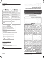
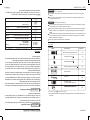
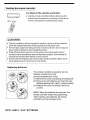
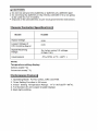
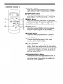
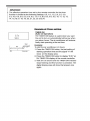
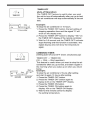
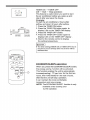
MODEL:
KU32085
AIR CONDITIONER
INSTRUCTION MANUAL
MANUAL DEL USUARIO
AIRE ACONDICIONADO
MODELO:
KU32085
CONTENTS
1 ESPAÑOL
DISPOSAL REQUIREMENTS
Proper disposal..................................................................................................................................2
SAFETY PRECAUTIONS
Safety rules .................................................................................................................... ...................3
Operating condition ............................................................................................................. ..............3
Electrical information .......................................................................................................... ...............4
AIR CONDITIONER FEATURES
Electronic control operating instructions ......................................................................................... ..6
NOTA
La información de voltaje que viene indicada en la etiqueta de electricidad se encuentra en base a las condiciones de prueba de instalación del
conducto de salida de aire sin extenderlo y sin los adaptadores A y B (el
conducto y los adaptadores A y B se encuentran listados en el cuadro de
accesorios de este Manual de Instrucciones).
IDENTIFICATION OF PARTS
Accessories .................................................................................................................... ...................4
Names of parts................................................................................................................... ................5
OPERATING INSTRUCTIONS
Operating instructions .......................................................................................................... .............7
14
CUIDADO Y MANTENIMIENTO
Cuidado y mantenimiento
9
9
12
13
INSTRUCCIONES DE INSTALACIÓN
Ubicación
Instalación del sistema para ventana
Instalación de la manguera de escape
Drenaje del agua
7
INSTRUCCIONES DE FUNCIONAMIENTO
Instrucciones de funcionamiento
6
CARACTERÍSTICAS DEL EQUIPO DE AIRE ACONDICIONADO
Instrucciones de funcionamiento del control electrónico
4
5
IDENTIFICACIÓN DE LAS PARTES
Accesorios
Nombres de las partes
3
3
4
PRECAUCIONES DE SEGURIDAD
Normas de seguridad
Condiciones de funcionamiento
Información eléctrica
2
REQUISITOS DE DESHECHO
Deshecho adecuado
NOTE
The rating data indicated on the energy label is based
on the testing condition of installing the un-extended
air exhaust duct without adaptor A & B (The duct and
the adaptor A & B are listed in the accessories chart
of the Instruction Manual).
1
1 ENGLISH
CONTENIDOS
TROUBLESHOOTING TIPS
Trouble shooting ................................................................................................................ ..............15
15
CARE AND MAINTENANCE
Care and maintenance ............................................................................................................. .......14
SOLUCIÓN DE PROBLEMAS
Solución de problemas
INSTALLATION INSTRUCTIONS
Location ....................................................................................................................... .....................9
Window kit installation .......................................................................................................... ............9
Exhaust hose installation ........................................................................................................ ........12
Water drainage .................................................................................................................. ..............13
ENGLISH 2
REQUISITOS DE DESHECHO
DESECHO: No deseche este producto como basura no clasificada. Póngase
en contacto con su municipalidad para obtener instrucciones sobre su
deshecho.
2
1.866.915.1212
PLEASE CALL:
FOR CUSTOMER SERVICE
PARA SERVICIO AL
CLIENTE POR
FAVOR LLAMAR:
1.866.915.1212
DISPOSAL: Do not dispose this product as unsorted municipal waste.
Please contact your local municipality for disposal instructions.
ESPAÑOL 2
DISPOSAL REQUIREMENTS
PRECAUCIONES DE SEGURIDAD
Normas de seguridad
Con el fin de prevenir lesiones y daños, debe seguirse las siguientes instrucciones. La utilización incorrecta del equipo podría causar lesiones o daños.
Siempre haga esto
• El equipo de aire acondicionado debe
utilizarse siempre de una manera en que
esté protegido de la humedad, por ejemplo de la condensación, salpicaduras de
agua, etc. No coloque el equipo de aire
acondicionado en donde pueda caerse al
agua o en cualquier otro líquido. Si esto
sucediera, desenchufe inmediatamente.
• Siempre traslade el equipo de aire
acondicionado de manera vertical y
colóquelo sobre una superficie estable
y nivelada durante su funcionamiento.
• Apague el equipo si no lo va a utilizar.
• Póngase en contacto con una persona calificada para llevar a cabo cualquier reparación. Si el cordón se
encontrara dañado, éste debe ser reparado por parte de un técnico calificado.
• Mantenga un espacio libre de
por lo menos 12” (30 cm.) alrededor del equipo con respecto a
las paredes, muebles y cortinas.
• Si el equipo se cayera o se volteara
durante su funcionamiento, apáguelo y desenchúfelo inmediatamente.
• Utilice siempre el botón de encendido en el panel de control.
Nunca haga esto
• No utilice el equipo de aire acondicionado en un ambiente húmedo
tal como un baño una lavandería.
• No toque el aparato con las manos húmedas o mojadas o si se
encuentra con los pies descalzos.
• No presione los botones en
el panel de control con otra
cosa que no sean sus dedos.
• No retire ninguna de las cubiertas
fijas. No utilice este electrodoméstico
si no está funcionando correctamente
o si ha sufrido una caída o daño.
• Nunca utilice el enchufe para encender o apagar el equipo directamente.
• No cubra ni obstruya las rejillas de ingreso y salida de aire.
• No utilice químicos peligrosos para
limpiar ni permita que entren en contacto con el aparato. No utilice el
equipo en la presencia de sustancias
o vapores inflamables tales como
alcohol, insecticidas, gasolina, etc.
• No permita que los niños utilicen
el equipo sin la debida supervisión.
• No utilice este equipo para otros
fines que no sean aquellos que vienen
descritos en el manual de instrucciones.
O
Ahorre Energía
O
• Utilice este equipo en un ambiente del tamaño recomendado.
• Coloque el equipo en un lugar donde los muebles no obstruyan el flujo de aire.
• Mantenga las persianas o cortinas cerradas durante la parte más soleada o
calurosa del día.
• Mantenga el filtro limpio.
• Mantenga las puertas y ventanas cerradas para mantener el aire frío dentro
del ambiente y mantener el aire caliente afuera.
>13 C/54 F
O
Condiciones de funcionamiento
• Este equipo de aire acondicionado debe utilizarse dentro de los rangos de
temperatura indicados más abajo.
DRY
O
TEMPERATURA DE AMBIENTE
> 17ºC / 62°F
> 13°C / 54°F
>17 C /62 F
FUNCIÓN ENFRIAMIENTO DESHUMEDECEDOR COOL
Your air conditioner should be used in such a way
that it is protected from moisture. e.g. condensation,
splashed water, etc. Do not place or store your air
conditioner where it can fall or be pulled into water
or any other liquid. Unplug immediately.
Always transport your air conditioner in a vertical
position and place on a stable, level surface during
use.
Turn off the product when not in use.
Always contact a qualified person to carry out
repairs. If the supply cord is damaged it must be
repaired by a qualified repair man.
Keep an air path of at least 12”(30cm) all around the
unit from walls, furniture and curtains.
If the air conditioner is knocked over during use,
turn off the unit and unplug from the main supply
immediately.
Always use the switch on the control panel.
Herramientas recomendadas para la instalación del sistema para ventana
1. Destornillador (tamaño mediano Phillips)
2. Cinta métrica o regla
3. Cuchillo o tijeras
4. Serrucho (En el caso de que se necesite cortar y reducir el tamaño del sistema para ventana si la ventana fuera demasiado angosta como para instalar el
sistema directamente).
ROOM TEMPERATURE
Energy Save
Never do this
Do not operate your air conditioner in a wet room
such as a bathroom or laundry room.
Do not touch the unit with wet or damp hands or
when barefoot.
Do not press the buttons on the control panel with
anything other than your fingers.
Do not remove any fixed covers. Never use this
appliance if it is not working properly, or if it has
been dropped or damaged.
Never use the plug to start and stop the unit.
Do not cover or obsturct the inlet or outlet grilles.
Do not use hazardous chemicals to clean or come
into contact with the unit. Do not use the unit in the
presence of flamable substances or vapor such
as alcohol, insecticides, petrol,etc.
Do not allow children to operate the unit
unsupervised.
Do not use this product for functions other than
those described in this instruction manual.
3
3 ENGLISH
3
1. Screwdriver(medium size Phillips)
2. Tape measurer or ruler
3. Knife or scissors
4. Saw(In the event that the window kit needs to be cut down in size because
the window is too narrow for direct installation)
Suggested tools for window kit installation
MODE
The air conditioner must be operated within the temperature range indicated below:
Operating condition
Use the unit in the recommended room size.
Place the unit where furniture cannot obstruct the air flow.
Keep blinds/curtains closed during the sunniest parts of the day.
Keep the filter clean.
Keep doors and windows closed to keep cool air in and warm air out.
Always do this
!
To prevent injury and property damage, the following instructions must be
followed. Incorrect operation may cause harm or damage.
Safety rules
SAFETY PRECAUTIONS
ENGLISH 4
4
Check all the accessories are included in the package and please refer to the installation instructions for
their usage.
NOTE: Optional parts(
), some models without.
FAN
HIGH
MED
LOW
TIMER ON
SET TEMPERATURE( C)
TEMP
AUTO
COOL
DRY
HEAT
ECONOMY
TIMER OFF
RESET LOCK
ON/OFF FAN SPEED
ION
SWING
MODE
FOLLOW
LED
ME
DISPLAY TURBO
“AAA”
Bateries
(for remote
controller)
Battery(for
remote
controller)
2/pc
Expansion Plug and Wooden Screw( )
4/ pc
Window Slider Kit
1 set
Foam Seal
3/pc
Remote Controller
(for remote control models only)
1pc
Wall Exhaust Adaptor A(
)
Adaptor B(round mouth) ( )
1 pc
1 set
IDENTIFICACIÓN DE LAS PARTES
ADVERTENCIA Para su seguridad
• No almacene ni utilice gasolina u otros vapores o líquidos inflamables cerca
de éste o de cualquier otro electrodoméstico.
• Evite el riesgo de que se produzca un incendio o una descarga eléctrica.
No utilice un cable de extensión ni un adaptador. No elimine ninguna de las
extremidades del enchufe.
ADVERTENCIA Información eléctrica
• Asegúrese de que su conexión eléctrica sea la adecuada para el modelo que
se ha adquirido. Esta información se puede encontrar en la placa informativa
que está ubicada en la parte lateral del equipo.
• Asegúrese de que el equipo de aire acondicionado cuente con la adecuada
conexión a tierra. Con el fin de minimizar el riesgo de una descarga eléctrica o
de que se produzca un incendio, la conexión a tierra resulta muy importante.
El cable cuenta con un enchufe de tres extremidades con salida a tierra para
evitar descargas eléctricas.
• El equipo de aire acondicionado debe conectarse a un tomacorriente con
la adecuada conexión a tierra. Si el tomacorriente que se desea utilizar no
cuenta con la debida conexión a tierra o no se encuentra protegido por un fusible de demora de tiempo o circuito interruptor, póngase en contacto con un
electricista calificado para instalar el tomacorriente adecuado.
• Asegúrese de que el tomacorriente quede en un lugar accesible después de
instalar el equipo.
Accesorios
Exhaust Hose and Adaptor B(flat mouth)
PARTS :
PARTS NAME :
1 set
QUANTITY :
Baterías “AAA” (para control remoto)
Do not store or use gasoline or other flammable vapors and liquids in the vicinity of this or any other
appliance.
Avoid fire hazard or electric shock. Do not use an extension cord or an adaptor plug. Do not remove
any prong from the power cord.
(sólo para modelos con control remoto)
WARNING
Control remoto
Empaquetadura de espuma
Sistema deslizador para ventana
Tarugo de expansión y tornillo de madera * 4 unidades
Adaptador de escape para pared A *
Adaptador B (boquilla redonda) *
Manguera de escape y
1 juego
Adaptador B
(boquilla plana)
Be sure the electrical service is adequate for the model you have chosen. This information can be found
on the rating label, which is located on the side of the cabinet.
Be sure the air conditioner is properly grounded. To minimize shock and fire hazards, proper grounding is
important. The power cord is equipped with a three-prong grounding plug for protection against shock
hazards.
Your air conditioner must be used in a properly grounded wall receptacle. If the wall receptacle you intend
to use is not adequately grounded or protected by a time delay fuse or circuit breaker, have a qualified
electrician install the proper receptacle.
Ensure the receptacle is accessible after the unit installation.
NOMBRE DE LAS PIEZAS:
PIEZAS:
Accessories
Electrical Infor mation
For your safety
WARNING
CANTIDAD
1 juego
1 unidad
1 juego
3 unidades
1 unidad
2 unidades
NOTA: Piezas opcionales (*). Algunos modelos no las incluyen.
• Verifique que todos los accesorios estén incluidos dentro del empaque y
véase las instrucciones instalación para su uso.
ESPAÑOL 4
IDENTIFICATION OF PARTS
IDENTIFICACIÓN DE LAS PARTES
5 ENGLISH
NOMBRES DE LAS PARTES
Vista Anterior
1. Panel de funciones
2. Rejilla con aspas horizontales
(manual)
3. Receptor de señal remota
4. Ruedas
5. Mango para cargar
(en ambos lados)
5
Fig.3
11
Air Intake
12
Lower Air Filter
(Behind the grill)
13
Bottom Tray Drain Outlet
Figura 2
10
10 Drain Outlet
8
Power Cord Outlet
9
Air Intake
Upper Air Filter
(Behind the grill)
7
Air Outlet
Vista Posterior
13
12
8
11
7
6
9
6
Rear
Fig.2
1
Operation Panel
2
Horizontal Louver Blade
(manual)
3
Remote Signal Receptor
4
Caster
5
Carrying Handle
(both sides)
1
6. Filtro de aire superior
(detrás de la rejilla)
7. Salida de aire
8. Salida para el cordón
9. Ingreso de aire
10. Salida de drenaje
11. Ingreso de aire
12. Filtro de aire inferior
(detrás de la rejilla)
13. Bandeja inferior para la
salida de drenaje.
4
5
3
2
Figura 3
Front
NAMES OF PARTS
5 ESPAÑOL
IDENTIFICATION OF PARTS
ENGLISH 6
CARACTERÍSTICAS DEL EQUIPO DE AIRE ACONDICIONADO
Instrucciones de funcionamiento del control eléctrico
5 FAN button
Control the fan speed. Press to select the fan
speed in four steps-LOW, MED, HI and AUTO.
The fan speed indicator light illuminates under
different fan settings except AUTO speed. When
select AUTO fan speed, all the fan indicator lights
turn dark.
4 SLEEP button
Used to initiate the SLEEP operation.
Antes de comenzar, familiarícese completamente con el panel de control y el
control remoto y todas sus funciones y luego siga los símbolos según las funciones necesarias.
Este equipo puede controlarse a través del panel de control solamente o a
través del control remoto.
NOTA: Este manual no incluye las instrucciones para el control remoto. Véase
el Manual de Instrucciones del Control Remoto dentro del empaque del equipo
para más detalles.
FUNCIONAMIENTO DEL PANEL DEL EQUIPO DE AIRE ACONDICIONADO
3 POWER button
Power switch on/off.
2 TIMER button
Used to initiate the AUTO ON start time and
AUTO OFF stop time program, in conjuction
with the
&
buttons.
1 MODE select button
Selects the appropriate operating mode.
Each time you press the button, a mode
is selected in a sequence that goes from
AUTO, COOL, DRY and, FAN .
The mode indicator light
illuminates under the different mode settings
Fig.4.
Fig.4
1
7
6
LED Display
O
Shows the set temperature in C or
O
F and the Auto-timer settings.
While on DRY and FAN modes, it shows
the room temperature.
Error codes:
E1- Room temperature sensor errorUnplug the unit and plug it back in.
If error repeats, call for service.
E2- Evaporator temperature sensor errorUnplug the unit and plug it back in.
If error repeats, call for service.
E4- Display panel communication errorUnplug the unit and plug it back in.
If error repeats, call for service.
P1- Bottom tray is full - Connect the
drain hose and drain the collected
water away. If error repeats, call
for service.
NOTE: The control is capable of displaying
temperature in degrees Fahrenheit or degrees
Celsius. To convert from one to the other, press
and hold the Up and Down buttons at the same
time, for 3 seconds.
UP ( ) and DOWN( ) button
Used to adjust (increase/decrease)
temperature settings(1 C/2 F increments)
in a range of 17 C(62 F) to 30 C(88 F) or
the TIMER setting in a range of 0~24hrs..
6
2
FA N
3
4
5
TIMER OFF
MO D E
SLEEP
DR Y
FA N
L OW
TIMER ON
F
AUTO
ME D
C
C OOL
HI
6
7
6
OPERATION PANEL OF THE AIR CONDITIONER
Before you begin, familiarize yourself with the control panel and remote controller
and all its functions, then follow the symbol for the functions you desire.
The unit can be controlled by the unit control panel alone or with the remote controller .
NOTE: This manual does not include Remote Controller Operations, see the <<Remote
Controller Instruction>> packed with the unit for details.
ELECTRONIC CONTROL OPERATING INSTRUCTIONS
AIR CONDITIONER FEATURES
1. Botón de selección de funciones MODE
Sirve para seleccionar la opción de funcionamiento adecuada. Cada vez que se presione este botón, se seleccionará una función
de manera secuencial que pasa por AUTO,
COOL (enfriamiento), DRY (deshumedecedor) y FAN (ventilador). La luz indicadora de
función se iluminará debajo de la opción seleccionada. Figura 4.
2. Botón del temporizador TIMER
Utilice este botón para iniciar el programa de
hora de encendido automático “AUTO ON” y
de hora de apagado automático “AUTO OFF”
en combinación con los botones
y
.
3. Botón de encendido POWER
Botón para encender y apagar.
4. Botón SLEEP
Utilizado para activar la función SLEEP
(apagado automático después de cierto periodo de tiempo).
5. Botón del ventilador FAN
Sirve para controlar la velocidad del ventilador. Presione para seleccionar la velocidad del ventilador en cuatro opciones: LOW
(baja), MED (media), HI (alta) y AUTO (automática). Las luces indicadoras de velocidad
de ventilador se iluminarán debajo de la opción seleccionada excepto bajo la velocidad
AUTO. Si se selecciona la velocidad de ventilador AUTO, todas las luces indicadoras del
ventilador quedarán desactivadas.
6. Botón Arriba
/ Abajo
Utilice este botón para regular (aumentar /
disminuir) los niveles de temperatura (en in-
crementos de 1°C / 2°F) dentro de un rango de
17°C (62°F) hasta 30°C (88°F) o en el caso de
usarse con el temporizador (TIMER), el rango
es de 0 a 24 horas.
NOTA: El panel de control puede mostrar la
temperatura en grados Fahrenheit o en grados Celsius. Para pasar de un sistema a otro,
presione y mantenga presionado los botones
Arriba (figura) / Abajo (figura) al mismo tiempo
durante 3 segundos
7. Pantalla LED
Muestra la temperatura seleccionada en grados “°C” o “°F” y las opciones del temporizador.
Bajo las opciones de DRY (deshumedecedor)
y FAN (ventilador), muestra la temperatura de
ambiente.
Códigos de error:
E1 – Error de sensor de temperatura de ambiente.
Desenchufe el equipo y vuélvalo a enchufar. Si
el error persiste, póngase en contacto con el
servicio técnico.
E2 – Error de sensor de temperatura del evaporador. Desenchufe el equipo y
vuélvalo a enchufar. Si el error persiste, póngase en contacto con el servicio técnico.
E4 – Error de comunicación del panel. Desenchufe el equipo y
vuélvalo a enchufar. Si el error persiste, póngase en contacto con el servicio técnico.
P1 – La bandeja inferior se encuentra llena. Conecte la manguera de drenaje y desagüe toda
el agua acumulada. Si el error persiste, póngase en contacto con el servicio técnico.
ESPAÑOL 6
Funcionamiento de enfriamiento – COOL
-Presione el botón “MODE” hasta que la luz
indicadora de “COOL” se ilumine.
- Presione y utilice los botones de AJUSTE y
para seleccionar la
temperatura de ambiente deseada. Se puede programar la temperatura dentro de un
rango de 17°C a 30°C / 62°F a 88°F.
- Presione el botón “FAN SPEED” para seleccionar la velocidad del ventilador.
Funcionamiento del deshumedecedor DRY
- Presione el botón “MODE” hasta que la luz
indicadora de “DRY” se ilumine.
- Bajo esta función, no se puede seleccionar la velocidad del ventilador ni regular la
temperatura. El motor del ventilador funcionará a velocidad baja (LOW).
- Mantenga las ventanas en las puertas cerradas para obtener un mejor resultado en el
retiro de humedad.
- No coloque el conducto en la ventana.
Funcionamiento automático – AUTO
- Si se coloca el equipo de aire acondicionado en la función AUTO, el equipo automáticamente seleccionará la opción de enfriamiento o solo de ventilador dependiendo de
la temperatura que se ha seleccionado y de
la temperatura de ambiente.
- El equipo de aire acondicionado controlará la temperatura de ambiente automáticamente según la temperatura predeterminada por el usuario.
- Bajo la función AUTO, no se puede seleccionar la velocidad del ventilador.
Funcionamiento del ventilador – FAN
- Presione el botón “MODE” hasta que la luz
indicadora de “FAN” se ilumine.
- Presione el botón “FAN SPEED” para seleccionar la velocidad del ventilador. El nivel
de temperatura no podrá regularse.
- No coloque el conducto en la ventana.
INSTRUCCIONES DEL FUNCIONAMIENTO
porizador) se iluminará. Esto indicará que
el programa de apagado automático se ha
iniciado.
- Con el aparato apagado, primero presione el botón TIMER. La luz indicadora de
TIMER ON (hora de encendido del temporizador) se iluminará. Esto indicará que el
programa de encendido automático se ha
iniciado.
- Presione o mantenga presionados los botones Arriba / Abajo para cambiar la hora de
encendido o apagado automático en incrementos de 0.5 horas hasta un máximo de
10 horas, y luego en incrementos de 1 hora
hasta un máximo de 24 horas. El control
efectuará un conteo regresivo del tiempo
restante hasta el inicio.
- El tiempo seleccionado quedará registrado en 5 segundos y el sistema automáticamente se revertirá as la pantalla anterior
para mostrar la opción de temperatura anterior.
- Si se enciende o se apaga el equipo en
cualquier momento o si se coloca el temporizador en 0.0, se cancelará la función de
encendido y apagado automático.
- Si se presentan los errores de desperfectos (E1 ó E2), el programa de encendido y
apagado automático también quedará cancelado.
Función de ahorro – SLEEP
Presione este botón y la temperatura seleccionada aumentará (enfriamiento) en 1°C
/ 2ºF durante 30 minutos. La temperatura
después aumentará (enfriamiento) en 1°C
/ 2ºF adicionales después de 30 minutos
adicionales. La nueva temperatura se mantendrá durante 7 horas antes de retornar a
la temperatura seleccionada originalmente.
Esto finalizará la función SLEEP y el equipo
continuará funcionando según su programación original.
SLEEP operation
Press this button, the selected temperature
will increase(cooling) by 1OC/2OF 30 minutes.
The temperature will then increase
(cooling) by another 1OC/2OF after an
additional 30 minutes. This new temperature will be maintained for 7 hours
before it returns to the originally selected
temperature. This ends the Sleep mode
and the unit will continue to operate as
originally programmed.
NOTE: This feature is unavailabe under
FAN or DRY mode.
-
When the unit is on, first press the
Timer button, the TIMER OFF
indicator light illuminates. It indicates the Auto Stop program is
initiated.
When the unit is off, first press the
Timer button, the TIMER ON indicator light illuminates. It indicates
the Auto Start program is initiated.
Press or hold the UP or DOWN
button to change the Auto time by
0.5 hour increments, up to 10 hours,
then at 1 hour increments up to 24
hours. The control will count down
the time remaining until start.
The selected time will register in 5
second and the system will automatically revert back to display the
previous temperature setting.
Turning the unit ON or OFF at any
time or adjusting the timer setting
to 0.0 will cancel the Auto Start/
Stop timed program.
When the malfunction (E1 or E2)
occurs, the Auto Start/Stop timed
program will also be cancelled.
NOTA: Esta función no se encuentra disponible bajo las opciones FAN y DRY.
The air conditioner will control room
temperature automatically around the
temperature point set by you.
Under AUTO mode, you can not
select the fan speed.
When you set the air conditioner in AUTO
mode, it will automatically select cooling or fan
only operation depending on what temperature
you have selected and the room temperature.
-
Funcionamiento del temporizador – TIMER
- Con el aparato encendido, primero presione el botón TIMER. La luz indicadora
de TIMER OFF (hora de apagado del tem-
7 ENGLISH
7
FAN operation
- Press the "MODE" button until the
"FAN " indicator light comes on.
- Press the "FAN SPEED" button to
choose the fan speed. The temperature
cannot be adjusted.
- Do not put the duct to window.
-
AUTO operation
TIMER operation
7 ESPAÑOL
DRY operation
- Press the "MODE" button until the "DRY" indicator
light comes on.
- Under this mode, you cannot select a fan speed or
adjust the temperature. The fan motor operates at
LOW speed.
- Keep windows and doors closed for the best
dehumidifying effect.
- Do not put the duct to window.
COOL operation
- Press the "MODE" button until the "COOL"
indicator light comes on.
- Press the ADJUST buttons " " or " " to
select your desired room temperature. The
temperature can be set within a range of
O
O
O
O
17 C-30 C/62 F-88 F.
- Press the "FAN SPEED" button to choose the
fan speed.
Operating Instructions
OPERATING INSTRUCTIONS
ENGLISH 8
INSTRUCCIONES DEL FUNCIONAMIENTO
Ajuste o regule manualmente
Funciones Adicionales
8
Falta de energía
En el caso de falta o interrupción de energía, el
equipo se reiniciará automáticamente bajo las opciones predeterminadas que se usaron por última
vez al momento que la energía retorne.
Espere 3 minutos antes de reanudar el funcionamiento
Después de que el equipo se haya apagado, no
puede reiniciarse el funcionamiento durante los
primeros 3 minutos. Esto es con el fin de proteger
el equipo. El funcionamiento se reiniciará automáticamente después de 3 minutos.
Regulación de la dirección del flujo de aire
Las rejillas se pueden regular manualmente. .
• Regulación de la dirección del flujo de aire de
manera manual
(Figura 5)
- La rejilla se puede colocar en la posición deseada de manera manual. El ángulo máximo es
de 60 grados. No fuerce la rejilla hacia un ángulo
mayor.
- No coloque objetos pesados ni otros artículos sobre la rejilla ya que esto podría dañar el equipo.
- Mantenga la rejilla totalmente abierta durante el
funcionamiento.
Fig.5
Adjust the air w direction manually
(Fig.5):
The louver can be set to the desired position
manually. The max setting angle is about
O
60 , please do not force to set any larger.
Do not place any heavy objects or other loads
on the louver, doing so will cause damage to
the unit.
Keep the louver fully opened during
operation.
Air ow direction adjustment
The louver can be adjusted manually
Wait 3 minutes before resuming operation
After the unit has stopped, it can not be restarted
operation in the first 3 minutes. This is to protect
the unit. Operation will automatically start after
3 minutes.
Power Outage
In the case of a power outage or interruption,
the unit will auto matically restart, in the
settings last used, after the power is restored.
Adjust manually
Other features
ESPAÑOL 8
OPERATING INSTRUCTIONS
Ventana horizontal
Sistema
deslizador
para
ventana
Mínimo: 67. 5 cm. (2.22 pies)
Máximo: 123 cm. (4.04 pies)
Ventana
horizontal
INSTRUCCIONES DE INSTALACIÓN
Ubicación
• El equipo de aire acondicionado debe colocarse sobre una superficie firme para reducir
el ruido y la vibración. Para una ubicación segura, coloque el equipo sobre un piso llano y
nivelado, lo suficientemente fuerte como para
soportar el peso del equipo.
• El equipo cuenta con ruedas para facilitar su
ubicación, pero sólo se deberá hacerse rodar
sobre superficies planas y llanas. Tenga cuidado a la hora de hacer rodar el equipo sobre alfombras. No intente hacerlo rodar por encima
de otros objetos.
• Coloque el equipo en un lugar en donde un
tomacorriente con la debida conexión a tierra
quede accesible.
• Nunca coloque obstáculos cerca del ingreso
o salida de aire del equipo.
• Deje por lo menos 12” (30 cm.) de espacio de
la pared para permitir el funcionamiento eficiente del sistema de aire acondicionado
Instalación del sistema para ventana
El sistema para ventana ha sido diseñado para
encajar en la mayoría de ventanas verticales y
horizontales. Sin embargo, puede ser necesario improvisar o modificar algunos aspectos
del procedimiento de instalación para el caso
de ciertos tipos de ventana. Véase las figuras
8 y 9 con respecto a las aperturas mínimas y
máximas de la ventana.
cm
Nota: Si la apertura de la ventana fuera menor
a la longitud mínima del sistema para ventana,
corte la pieza que tiene agujeros para que
pueda encajar en la ventana. No corte el agujero que se encuentra en el sistema deslizador
para ventana.
Horizontal
window
Your window kit has been designed to fit most
standard vertical and horizontal window
applications. However, it may be necessary for you to
improvise/modify some aspects of the installation
procedures for certain types of window. Please refer
to Fig. 8 & Fig.9 for minimum and maximum window
openings.
Window kit Installation
m
Sistema deslizador
para ventana
Mínimo: 67.5 cm. (2.22 pies)
Máximo: 123 cm. (4.04 pies)
9 ENGLISH
9
Fig.9
Window Slider Kit
Minimum:67.5cm(2.22ft).
Maxmum:123cm(4.04ft).
Note: If the window opening is less than the mentioned
minimum length of the window slider kit, cut that one
with holes in it short to fit for the window opening.
Never cut out the hole in window slider kit.
Fig.8
Window Slider Kit
Minimum:67.5cm(2.22ft).
Maxmum:123cm(4.04ft).
Horizontal
window
Fig.7
30
30c
The air conditioner should be placed on a firm
foundation to minimize noise and virbration. For
safe and secure positioning, place the unit on a
smooth, level floor strong enough to support the unit.
The unit has casters to aid placement, but it should
only be rolled on smooth, flat surfaces. Use caution
when rolling on carpet surfaces. Do not attempt to
roll the unit over objects.
The unit must be placed within reach of a properly
rated grounded socket.
Never place any obstacles around the air inlet or
outlet of the unit.
Allow at least 12”(30cm) of space from the wall for
efficient air-conditioning.
Location
INSTALLATION INSTRUCTIONS
9 ESPAÑOL
INSTALLATION INSTRUCTIONS
ENGLISH 10
INSTRUCCIONES DE INSTALACIÓN
Instalación en ventanas con bastidores
de doble hoja
10
Fig.13
Foam seal
Fig.12
1. Corte la empaquetadura de espuma (tipo
adhesivo) según la longitud necesaria y adhiérala al marco de la ventana. Figura 10.
2. Acople el sistema deslizador para ventana al marco de la ventana. Regule la longitud del deslizador de acuerdo al ancho de
la ventana. Acorte el deslizador si el ancho
de la ventana es menor a 27 pulgadas.
Abra el bastidor de la ventana y coloque
el deslizador para ventana en el marco.
Figura 11.
3. Corte la empaquetadura de espuma (tipo
adhesivo) según la longitud necesaria para
colocarla en la parte superior de la ventana.
Véase la figura 12.
4. Cierre el bastidor de la ventana y verifique que quede asegurado.
5. Corte la empaquetadura de espuma
según la longitud necesaria y selle el espacio entre la parte superior del bastidor de la
ventana y el bastidor externo de la ventana.
Véase la figura 13.
Empaquetadura de
espuma A
(tipo adhesivo)
Sistema para
ventana
Soporte de la
ventana
Window stile
Sistema para
ventana
Window kit
Soporte de la
ventana
Fig.11
Window stile
5. Cut the foam seal to an appropriate length and sealing the
open gap between the top window sash and outer window
sash. Show as in Fig.13.
4. Close the window sash securely against the window.
3. Cut the foam seal(adhesive type) to the proper length
and attach it on the top of the window. Show as in Fig.12
26.5 ~ 48
Empaquetadura de
espuma
Window kit
Fig.10
2. Attach the window slider kit to the window stool. Adjust the
length of the window slider kit according to the width of
window, short the adjustable window kit if the width of
window is less than 27 inches.
Open the window sash and place the window slider kit on
the window stile. Fig.11
1. Cut the foam seal(adhesive type) to the proper length and
attach it to the window stool. Fig.10
Foam seal A
(adhesive type)
Installation in a double-hung sash
windows
ESPAÑOL 10
INSTALLATION INSTRUCTIONS
INSTRUCCIONES DE INSTALACIÓN
11 ENGLISH
Instalación en ventanas con bastidores deslizables
1. Corte la empaquetadura de espuma
(tipo adhesivo) según la longitud necesaria y adhiérala al marco de la ventana.
Véase la figura 14.
2. Coloque el deslizador para ventana en
el marco de la ventana. Regule la longitud
del deslizador de acuerdo al ancho de la
ventana. Acorte el deslizador si el ancho
de la ventana es menor a 27 pulgadas.
Abra el bastidor de la ventana y coloque
el deslizador sobre el marco. Véase la
figura 15.
3. Corte la empaquetadura de espuma
(tipo adhesivo) según la longitud necesaria y adhiérala a la parte superior de la
ventana. Véase la figura 16.
4. Cierre el bastidor deslizable de manera
que quede asegurado.
5. Corte la empaquetadura de espuma
según la longitud necesaria y selle el espacio entre la parte superior del bastidor
de la ventana y el bastidor externo de la
ventana. Véase la figura 17.
Empaquetadura de
espuma A
(tipo adhesivo)
11
Fig.17
Panel de la
ventana
Foam seal
Fig.16
5. Cut the foam seal to an appropriate length and sealing the
open gap between the top window sash and outer window
sash. Show as in Fig.17.
4. Close the sliding sash securely against the window.
3. Cut the foam seal(adhesive type) to the proper length
and attach it on the top of the window. Show as in Fig.16.
2. Attach the window slider kit to the window stool. Adjust the
length of the window slider kit according to the width of
window, short the adjustable window kit if the width of
window is less than 27 inches.
Open the window sash and place the window slider kit on
the window stile. See Fig.15.
Empaquetadura
de espuma
Fig.15
26.5 ~ 48
Window
panel
Fig.14
Foam seal A
(adhesive type)
1. Cut the foam seal(adhesive type) to the proper length and
attach it to the window frame. See Fig.14.
Installation in a sliding sash windows
11 ESPAÑOL
INSTALLATION INSTRUCTIONS
ENGLISH 12
INSTRUCCIONES DE INSTALACIÓN
Instalación de la manguera de escape
La manguera de escape y el adaptador deben
instalarse o retirarse de acuerdo a la función de
uso.
12
Función (enfriamiento)
Fig.22
Empuje hacia adentro
Gancho
Figura 19
Fig.21
min 30CM
max 120CM
DO NOT OVER BEND THE DUCT (See Fig.22)
IMPORTANT:
Figura 20
Adaptor A
Adaptor
cap
The duct can be compressed or extended moderately
according to the installation requirement, but it is
desirable to keep the duct length to a minimum.
Expansion plug
position
Fig.20
Posición del tarugo
de expansión
Adaptador A
Tapón del adaptador
Función (ventilador) o
DRY (deshumedecedor)
Debe instalarse
Debe retirarse
1. Instale el adaptador de salida de ventana B
(boquilla plana) a la manguera de escape como
se muestra la figura 18a ó 18b. Véase las páginas anteriores sobre la instalación del sistema
para ventana.
2. Para una instalación rápida, coloque la
manguera de escape en la abertura de salida de
aire utilizando el gancho (Véase la Fig. 19) y estire el otro extremo (Fig. 20) como se muestra en
la figura 20.
La manguera de escape se puede instalar en la
pared (No disponible para equipos sin el adaptador A, los tarugos de expansión y los tornillos
de madera)
1. Prepare un agujero en la pared. Instale el
adaptador A en la pared (afuera) utilizando los
cuatro tarugos de expansión y los tornillos de
madera. Asegúrese de fijarlos completamente
(Véase la figura 21)
2. Acople la manguera de escape al adaptador
de pared A.
Nota:
Cubra el agujero utilizando el tapón del adaptador si no se encuentra en uso.
Figura 21
Hook
Fig.19
• La manguera de escape se puede comprimir o
estirar moderadamente de acuerdo a los requisitos de instalación, pero es recomendable mantener la longitud de la manguera al mínimo.
IMPORTANTE:
Pu
s
h in
NO DOBLE DEMASIADO LA MANGUERA DE
ESCAPE (Véase la figura 22)
Fig.18a
Fig.18b
Note:
Cover the hole using the adaptor cap when not in use.
1. Install the window Exhaust adaptor B onto the exhaust
hose as shown in Fig.18a. or Fig.18b. Refer to the previous
pages for window kit installation.
2. Place the Exhaust hose over against the air outlet opening
hook(See Fig.19) and flat the other end(See Fig.20) for
quick installation.
The exhaust hose can be installed into the wall
(Not applicable to the units without adaptor A, expansion
plugs and wooden screws of Accessories ).
1. Prepare a hole in the wall. Install the wall Exhaust adaptor A
onto the wall(outside) by using 4 expansion plugs and
wooden screws, be sure to fix thoroughly. (See Fig.21)
2. Attach the Exhaust hose to wall Exhaust adaptor A.
COOL mode
Install
FAN or DEHUMIDIIFY mode
Remove
The exhaust hose and adaptor must be installed or removed
in accordance with the usage mode.
Exhaust hose installation:
ESPAÑOL 12
INSTALLATION INSTRUCTIONS
Retire el tapón de drenaje
Figura 23
Manguera de
drenaje continuo
INSTRUCCIONES DE INSTALACIÓN
13 ENGLISH
Drenaje del agua:
- Durante la opción de deshumedecedor, retire el
tapón de drenaje en la parte posterior del equipo.
Conecte el conector de drenaje (unión hembra
universal de 5/8”) con una manguera de 3/4”
(que se puede adquirir en cualquier tienda). Para
aquellos modelos sin conector de drenaje, simplemente acople la manguera de drenaje al agujero. Coloque el extremo abierto de la manguera
directamente sobre la zona de drenaje o un sumidero en el piso. Véase las figuras 23 y 24.
- Cuando el nivel de agua de la bandeja inferior alcance un nivel predeterminado, el equipo
emitirá unos sonidos “beep” 8 veces. La pantalla
mostrará “P1” y el proceso de enfriamiento o del
deshumedecedor se detendrá. Sin embargo, el
motor del ventilador continuará funcionando.
(Esto es normal).
Con cuidado traslade el equipo a la zona donde
se vaya a drenar el agua. Retire el tapón de
drenaje inferior y desagüe del agua (figura 25).
Reinicie el funcionamiento del aparato hasta que
el símbolo “P1” desaparezca. Si el error se repitiera, póngase en contacto con el servicio técnico.
13
Fig.25
Fig.24
repeats, call for service.
until the P1 symbol disappears. If the error
water drain away(Fig.25). Restart the machine
remove the bottom drain plug and let the
Figura 24
Carefully move the unit to a drain location,
continue to operate(this is normal).
immediately stop. However, the fan motor will
the air conditioning/dehumidification process will
Continuous
drain hose
-
the digital display area shows P1 . At this time
a predetermined level, the unit beeps 8 times,
When the water level of the bottom tray reaches
Fig.23
basement floor. Please refer to Fig.23 & 24.
hose directly over the drain area in your
Figura 25
hose to the hole. Place the open end of the
without drain connector, just attach the drain
3 4 hose(locally purchased). For the models
connector(5/8 universal female mender) with
Remove the
drain plug
plug from the back of the unit, install the drain
-
During dehumidifying mode, remove the drain
Water drainage:
13 ESPAÑOL
INSTALLATION INSTRUCTIONS
ENGLISH 14
CUIDADO Y MANTENIMIENTO
Filtro de aire
(Deslice hacia afuera)
Figura 26
14
Fig.30
Fig.29
-
Band
Power cord
Fig.28
Remove the air filter
out from the grille
Remove the rubber plug at the back of the unit and attach
a hose to drain outlet. Place the open end of the hose
directly over the drain area in your basement floor
(See Fig.23 & 24).
Remove the plug from the bottom drain outlet, all the water
in the bottom tray would drain out (See Fig.25).
Keep the appliance running on FAN mode for half a day in
a warm room to dry the appliance inside and prevent mold
forming.
Stop the appliance and unplug it, wrap the cord and
bundle it with the tape(Fig.29). Remove the batteries from
the remote controller.
Clean the air filter and reinstall it.
Unscrew the exhaust hose to the right or left and pull out
for uninstallation(Fig.30), keep it safely, and cover the
window(wall) hole with the adaptor cap.
3. Unit idle for a long time
2. Unit enclosure
- Use a lint-free cloth soaked with neutral detergent to clean
the unit enclosure. Finished by a dry clean cloth.
-
Fig.27
-
Remove the
screw and
take the air
inlet grille
down
-
Clean the air filter at least once every two weeks to prevent
inferior fan operation because of dust.
Removal
This unit has two filters. Grasp the upper filter tab(Fig.26),
,,
,,
,,
,,
pull the filter out then up . Remove the lower filter by
loosening the screw, taking down the air inlet grille, then
removing the air filter as shown in Fig.27 & 28.
Cleaning
Wash the air filter by immersing it gently in warm water
O
O
(about 40 C/104 F) with a neutral detergent. Rinse the filter
and dry it.
Mounting
Insert the upper air filter from top after cleaning, attach
the lower air filter on the air inlet grille, then install the grille
by using the screw.
1. Air
Fig.26
Air filter
(slide out)
IMPORTANT:
1) Be sure to unplug the unit before cleaning or servicing.
2) Do not use gasoline, thinner or other chemicals to clean
the unit.
3) Do not wash the unit directly under a tap or using a hose.
It may cause electrical danger.
4) If the power cord is damaged, it should be repaired by
a qualified repair man.
CARE AND MAINTENANCE
CARE AND MAINTENANCE
IMPORTANTE:
1)Asegúrese de desenchufar el aparato antes
de proceder con la limpieza o efectuar cualquier tipo de mantenimiento.
2) No utilice gasolina, diluyente u otros químicos para limpiar el equipo.
3) No lave el equipo directamente bajo el agua
o utilizando una manguera. Esto puede causar eventualidades eléctricas.
4) Si el cordón se dañara, éste debe ser reparado por parte de un técnico calificado.
1. Filtro de aire
- Limpie el filtro de aire por lo menos una
vez cada dos semanas para evitar el funcionamiento indeficiente del ventilador debido al
polvo.
- Cómo retirar el filtro
Este equipo cuenta con dos filtros. Sujete la
lengüeta del filtro superior (figura 26) y tire del
Retire los tres tornillos
filtro hacia afuera y hacia arriba para sacarlo.
y saque y retire la reRetire el filtro inferior soltando los tornillos,
jilla de ingreso de aire
retirando la rejilla de ingreso de aire y luego
sacando el filtro de aire como se muestra en
Figura 27
las figuras 27 y 28.
- Limpieza
Lave el filtro sumergiéndolo con cuidado en
agua tibia (aproximadamente 40°C / 104ºF) utilizando
detergente neutral. Enjuague el filtro y déjelo
Retire el filtro de
secar.
aire de la rejilla
- Cómo volver a colocar los filtros
Inserte el filtro superior desde arriba después
Figura 28
de limpiarlo. Acople el filtro inferior de aire a
la rejilla de ingreso de aire y luego instale la
Cordón de
rejilla utilizando los tornillos.
alimentación
2. Cómo limpiar el exterior del equipo
- Utilice un paño libre de pelusas humedecido
con detergente neutral para limpiar el exterior
del equipo. Termine utilizando un paño limpio
y seco.
3. Equipo sin uso durante un periodo prolongado
Figura 29
- Retire el tapón de jebe en la parte posterior
del equipo y coloque la manguera a la salida
de drenaje. Coloque la parte abierta de la
manguera directamente sobre la zona de drenaje o un sumidero en el piso (véase las figuras 23 y 24).
- Retire el tapón de la salida de drenaje inferior
para permitir el desagüe de toda el agua acumulada en la bandeja inferior (véase la figura
25).
- Mantenga el equipo funcionando bajo la función FAN durante mediodía en un ambiente
tibio para permitir que el electrodoméstico
Figura 30
se seque por dentro y evitar la formación de
moho.
ESPAÑOL 14
- Apague el equipo y desenchúfelo. Enrolle el cordón y enróllelo juntándolo con cinta (véase
la figura 29). Retire las baterías del control remoto.
- Limpie el filtro de aire y vuelva a colocarlo.
- Desconecte la manguera de escape girándola y tirando hacia fuera (Fig. 30). Guárdela en
un lugar seguro y proceda cubrir el agujero de la ventana (pared) con el tapón del adaptador.
15 ENGLISH
15
SOLUCIÓN DE PROBLEMAS
Drene el agua de la de la bandeja inferior
1. El equipo no funciona - P1 aparece en la al presionar el botón de pantalla encendido - La temperatura de la
habitación es menor que la temperatura
programada
Solución recomendada
Problema
Causa posible
- El piso no está nivelado o no es lo suficientemente plano - Las ventanas o puertas de la habitación no están
cerradas - Hay fuentes de calor dentro de la habitación
- La manguera de escape de aire no está conectada
o se encuentra obstruida
- La temperatura programada es demasiado alta
- El filtro de aire se encuentra obstruido
con polvo
2. No enfría lo suficiente
Reprograme la
temperatura
(función de enfriamiento)
Asegúrese de que todas las ventanas y
puertas estén cerradas
Retire las fuentes de
calor si fuera posible
Conecte la manguera
y asegúrese de que funcione adecuadamente
Disminuya la temperatura
programada
Limpie el filtro de aire
Place the unit on a flat, level
Coloque el equipo sobre
una superficie plana y
nivelada si es posible
Esto es normal.
Clean the air filter.
4. Se produce ruido o vibraciones It is normal.
ground if possible.
- Air filter is blocked by dust.
- Este sonido se produce - The sound comes from the flowing
- The ground is not level or not flat
Decrease the set temperature.
sure it can function properly.
5. Sonido gluglú debido al fluido del
refrigerante dentro del
equipo de aire
acondicionado
air-conditioner.
of the refrigerant inside the
5. Gurgling sound
enough.
4. Noisy or vibration
- Temperature setting is too high.
blocked.
- Exhaust air duct is not connected or
2. Not cool enough
Connect the duct and make
room.
- There are heat sources inside the
are not closed.
- The windows or doors in the room
Button
Pressing
the set temperature.(Cooling mode)
- Room temperature is lower than
Remove the heat sources if possible.
doors are closed.
Make sure all the windows and
Reset the temperature.
Start when
TROUBLES
POSSIBLE CAUSES
SUGGEST REMEDIES
1. Unit does not
- P1 appears in the display window
Drain the water in the bottom tray.
TROUBLE SHOOTING
15 ESPAÑOL
TROUBLESHOOTING TIPS