1
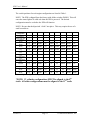
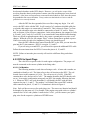
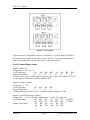
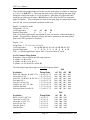
User’s Manual Electromotive, Inc. 9131 Centreville Rd. Manassas, VA 20110 (703) 331-0100 Fax: (703) 331-0161 XDI User’s Manual Table of Contents List of Figures ..................................................................................................................... 2 Terms and Conditions ......................................................................................................... 3 Value Added Dealers ...................................................................................................... 3 Electromotive Product Warranty .................................................................................... 3 Warranty Replacement................................................................................................ 3 Warranty Coverage ..................................................................................................... 3 Length of Warranty..................................................................................................... 3 Who the Warranty Protects......................................................................................... 4 Warranty Exclusions................................................................................................... 4 How to Obtain Warranty Service................................................................................ 4 LIMITATION OF IMPLIED WARRANTIES .......................................................... 5 EXCLUSION OF DAMAGES ................................................................................... 5 1.0 XDI Overview............................................................................................................... 6 1.1 How Direct Fire Ignition Works ............................................................................... 6 1.2 High Resolution Single-Crankshaft-Sensor Decoding ............................................. 6 1.3 Choosing Spark Plugs and Wires.............................................................................. 7 1.3.1 Spark Plug Wire Selection ................................................................................. 7 1.3.2 Spark Plug Selection .......................................................................................... 8 2.0 Engine Configuration Guide ....................................................................................... 10 2.1 Engine Configuration Settings................................................................................ 10 3.0 Hardware Installation.................................................................................................. 12 3.1 Pre-Installation Checklist........................................................................................ 12 3.2 Cautions and Warnings ........................................................................................... 12 3.3 Installing the Direct Fire Unit (DFU) ..................................................................... 13 3.4 Installing the XDI ................................................................................................... 13 3.5 Trigger Wheel and Sensor Installation .................................................................. 14 3.5.1 Crankshaft Trigger Installation for 60(-2) Tooth Wheel ................................ 14 3.5.2 Magnetic Crank Sensor Installation................................................................ 15 4.0 Wiring ......................................................................................................................... 18 4.1 Introduction............................................................................................................. 18 4.2 Wiring the DFU’s ................................................................................................... 20 4.2.1 DFU to XDI ..................................................................................................... 20 4.2.2 DFU to Spark Plugs ......................................................................................... 21 4.3 Crank Sensor........................................................................................................... 26 4.4 Power and Ground .................................................................................................. 26 5.0 Functional Description................................................................................................ 28 5.1 Overview of Ignition Timing .................................................................................. 28 5.2 Adjusting the Timing .............................................................................................. 29 5.2.1 Initial Knob ...................................................................................................... 29 5.2.2 “3000” Knob .................................................................................................... 29 5.2.3 “8000” Knob .................................................................................................... 30 5.3 Measuring Timing................................................................................................... 31 5.4 External Advance Control....................................................................................... 31 5.4.1 Vacuum Advance (a.k.a. Boost Retard)........................................................... 32 Version 1.1 Page 1 2004 Electromotive, Inc. XDI User’s Manual 5.5 External Retard Control .......................................................................................... 33 5.5.1 Backup Sensor ................................................................................................. 33 5.6 Tachometer Output ................................................................................................. 34 5.6 Primary and Auxiliary Rev Limiter ........................................................................ 35 6.0 Diagnostics.................................................................................................................. 36 Appendix A....................................................................................................................... 37 Appendix B ....................................................................................................................... 38 List of Figures Figure 1 - Picture of XDI with Cover Plate Removed...................................................... 10 Figure 2 - 2-Coil DFU Dimensions .................................................................................. 13 Figure 3 – 3-Coil DFU Dimensions.................................................................................. 13 Figure 4 - XDI Dimensions............................................................................................... 14 Figure 5 - TDC tooth for the four possible scenarios. ...................................................... 16 Figure 6 - Correct sensor alignment.................................................................................. 17 Figure 7 - Included components for wiring harness ......................................................... 19 Figure 8 - Coil notation..................................................................................................... 22 Figure 9 - Crank trigger connections ................................................................................ 26 Figure 10 - Recommended power connections for a two DFU configuration.................. 27 Figure 11 - Recommended power connections for a one DFU configuration.................. 27 Figure 12 - Knobs used for setting timing and RPM limit ............................................... 29 Figure 13 - Timing curve for the example discussed and shown in Figure 12................. 30 Figure 14 - Measuring timing with a digital voltmeter..................................................... 31 Figure 15 - Graph of input voltage vs. additional advance............................................... 32 Figure 16 - MAP sensor connection ................................................................................. 32 Figure 17 - Graph of input voltage vs. addional retard..................................................... 33 Figure 18 - Backup sensor location .................................................................................. 34 Figure 19 - Typical tachometer connections..................................................................... 35 Version 1.1 Page 2 2004 Electromotive, Inc. XDI User’s Manual Terms and Conditions Value Added Dealers Electromotive products are sold exclusively through our worldwide network of Value Added Dealers (VAD’s). These dealers supplement our products with their experience and installation skills for many specific applications. Electromotive Product Warranty Only products Manufactured by Electromotive are covered by Electromotive’s limited warranty for a period of one-year from date of shipment by Electromotive. Products not manufactured by Electromotive are expressly excluded from any consideration under these terms – for information regarding products not manufactured by Electromotive you must contact the specific product’s manufacturer. Whenever possible, Electromotive attempts to replace defective products rather than repair them. Replacement puts the "Customer First" and offers many benefits over repair; the greatest benefit being the timeliness of the replacement process. However, in some cases, replacement with a ‘like new’ refurbished product is not possible, and a warranty repair situation occurs. In these situations, Electromotive strives to keep our repair times to a minimum (on average 2 to 3 business days upon receipt - excluding the necessary shipping time). Customers should follow the appropriate steps outlined below to initiate a warranty replacement or repair. Warranty Replacement Contact Electromotive Technical Support at 1-703-331-0100 9am to 5pm Eastern Time. The customer must have the serial number and original proof-of-purchase available. Electromotive’s Technical Support staff will attempt to help you correct any minor issues that might be causing the problem. If we are unable to fix the issue to your satisfaction, a return merchandise authorization (RMA) number will be issued. Under our Warranty program, Electromotive will typically ship the customer a replacement unit on the same day the defective product arrives. The replacement product will assume the remainder of your original product's warranty or 90 days, whichever is greater. Warranty Coverage Electromotive warrants its products to be free from defects in material and workmanship during the warranty period. If a product proves to be defective in material or workmanship during the warranty period, Electromotive will, at its sole option, repair or replace the product with a similar product. Replacement product or parts may include remanufactured or refurbished parts or components. Length of Warranty Electromotive products are warranted for one (1) year parts and one (1) year labor. Warranty begins upon date of shipment from Electromotive. Version 1.1 Page 3 2004 Electromotive, Inc. XDI User’s Manual Who the Warranty Protects This warranty is valid only for the purchaser from Electromotive. Warranty Exclusions 1. 2. 3. 4. 5. 6. 7. 8. 9. Any product, on which the serial number has been defaced, modified or removed. Damage, deterioration or malfunction resulting from: A. Accident, misuse, neglect, fire, water, lightning, or other acts of nature, unauthorized product modification, or failure to follow instructions supplied with the product. B. Repair or attempted repair by anyone not authorized by Electromotive. C. Any damage of the product due to shipment. D. Removal or installation of the product. E. Causes external to the product, such as electric power fluctuations or failure. F. Use of supplies or parts not meeting Electromotive’s specifications. G. Any other cause, which does not relate to a product defect. Removal, installation, and set-up service charges. Shipping Charges. Any warranty of merchantability, express or implied, is excluded except as otherwise set forth herein. There are no warranties that extend beyond the description on the face of this document. There are no warranties of fitness for a particular purpose except as stated on the face of this “Electromotive Product Warranty”. Any and all oral warranties are excluded and will not be honored. Consequential damages will not be covered by this warranty. How to Obtain Warranty Service 1. 2. For information on warranty service, contact your Electromotive Value Added Dealer or call Electromotive Technical Support at 1-703-331-0100 from 9am to 5pm Eastern Time Monday through Friday - e-mail [[email protected]]. To obtain warranty service, you will be required to provide: a. Original dated sales receipt b. Your name c. Your address d. The serial number of the product e. A description of the problem f. Contact information (daytime phone number or email address) Take or ship the product in the original or a suitable replacement container to: Electromotive, Inc. 9131 Centreville Road Manassas VA 20110 Version 1.1 Page 4 2004 Electromotive, Inc. XDI User’s Manual LIMITATION OF IMPLIED WARRANTIES THERE ARE NO WARRANTIES, EXPRESS OR IMPLIED, WHICH EXTEND BEYOND THE DESCRIPTION CONTAINED HEREIN INCLUDING THE IMPLIED WARRANTY OF MERCHANTABILITY AND FITNESS FOR A PARTICULAR PURPOSE. EXCLUSION OF DAMAGES ELECTROMOTIVE’S LIABILITY IS LIMITED TO THE COST OF REPAIR OR REPLACEMENT OF THE PRODUCT. ELECTROMOTIVE SHALL NOT BE LIABLE FOR: 1. DAMAGE TO OTHER PROPERTY CAUSED BY ANY DEFECTS IN THE PRODUCT, DAMAGES BASED UPON INCONVENIENCE, LOSS OF USE OF THE PRODUCT, LOSS OF TIME, LOSS OF PROFITS, LOSS OF BUSINESS OPPURTUNITY, LOSS OF GOODWILL, INTERFERENCE WITH BUSINESS RELATIONSHIPS, OR OTHER COMMERCIAL LOSS, EVEN IF ADVISED OF THEIR POSSIBILITY OF SUCH DAMAGES. 2. ANY OTHER DAMAGES, WHETHER INCIDENTAL, CONSEQUENTIAL OR OTHERWISE. 3. ANY CLAIM AGAINST THE CUSTOMER BY ANY OTHER PARTY. 4. SHIPPING CHARGES. Version 1.1 Page 5 2004 Electromotive, Inc. XDI User’s Manual 1.0 XDI Overview The XDI is the latest ignition system from Electromotive. This new, configurable ignition system uses a controller with one or two Direct Fire Units (DFU) to power up to 14 different engine configurations. The XDI uses Electromotive’s patented direct fire ignition and it’s high-resolution crank position sensing to produce the most accurate and most powerful ignition available in the aftermarket. 1.1 How Direct Fire Ignition Works A "Direct Fire" ignition fires the spark plugs directly from the coils and not through a distributor cap and rotor. This is accomplished by using multiple coils, each with two spark terminals. The coil terminals are connected to the spark plugs, allowing one cylinder to fire on compression while its companion cylinder fires simultaneously on exhaust. Open spark gaps in the rotor and cap are eliminated, making wear and moisture problems a thing of the past. What sets XDI apart is the ability to charge multiple ignition coils at the same time. This increased dwell time means that full spark energy is available over the entire RPM range (up to 9600 at 12 volts). Unlike Capacitive Discharge systems that only put out one very short spark, the XDI puts out a full energy, long burning spark at your highest and most critical engine speeds. Long burn times assure effective burning of even lean fuel mixtures. The brain of the XDI includes dual digital microprocessors using patented spark algorithms (patent number RE 34,183), which takes the electrical signal from the crankshaft sensor, identifies the two missing teeth and then keeps track of the remaining 58 teeth. The XDI determines engine speed and computes the spark advance from your knob settings. Setting the timing advance curve is a simple task that anyone can understand. In addition to synchronizing and firing the plugs at the correct advance angle, the XDI also computes the exact dwell to produce 9 amps of coil current. Coil charging is measured dynamically, so changes in RPM, battery voltage, or temperature are all accounted for on every spark. This corrects any errors that are caused by battery voltage or coil temperature changes and insures maximum spark energy. 1.2 High Resolution Single-Crankshaft-Sensor Decoding Some OEM direct ignition systems use both a crankshaft and a camshaft sensor assembly, making the system more complicated and more expensive than it needs to be. Other systems use low resolution, four to ten tooth trigger wheels on either the crankshaft or camshaft; these are not enough teeth to assure that the coils are firing without timing errors. The XDI solves these problems with a single, high resolution, 60-minus-2 tooth crank trigger wheel. This affords resolution unheard of in any other electronic ignition available today, offering spark accuracy of ¼ degree of crankshaft rotation. This accuracy makes the system ideal for the most demanding engines. Version 1.1 Page 6 2004 Electromotive, Inc. XDI User’s Manual In summary, your Electromotive XDI delivers more power because: • • • • • • • • • • • Spark timing is precisely controlled under all conditions, including rapid engine acceleration Crank trigger eliminates spark scatter due to gear lash and timing chain stretch Accurate spark timing allows sustained engine operation closer to peak power timing 100% spark energy to 9600 RPM on 6 cylinder and 12,000 RPM on 4 & 8 cylinder applications (at 12 volts) Operation up to 20,000 RPM (at higher battery voltage) Long, 2000 microsecond (typical) spark duration - 60° duration at 10,000 RPM! Built-in timing computer and rev limiter No power draining magnetos or distributors to drive No moving parts to wear out or replace Built-in timing monitor lets you measure the advance with a voltmeter Options include: backup sensor, dual rev limiter, and remote timing control 1.3 Choosing Spark Plugs and Wires 1.3.1 Spark Plug Wire Selection The XDI outputs an extremely high-energy charge for the ignition coils. Resistor (carbon) core wires work best with this charging method, since they absorb electrical noise generated by the coil firing events. Use 8mm or larger RFI and EMI suppression wire with GM boots. We recommend using a carbon core-style suppression wire with a resistance of 3,000 to 5,000 ohms per foot. SOLID CORE WIRES SHOULD NEVER BE USED. Do not be misled by spark plug wire manufacturers claiming to give you a “power increase” from their wire. The bottom line is that with our charging method, different spark plug wires simply do not make a difference in terms of spark energy. However, there is a huge difference in noise generated by different spark plug wire types (solid core wires generate a very high amount of noise with our system). Paraphrased from Magnecor’s Website: “What is not generally understood (or is ignored) is that the potential 45,000 plus volts (with alternating current characteristics) from the ignition coil does not flow through the entire length of fine wire used for a spiral conductor like the 1 volt DC voltage from a test ohmmeter, but flows in a magnetic field surrounding the outermost surface of the spiral windings (skin effect). The same skin effect applies equally to the same pulsating flow of current passing through carbon and solid metal conductors. A spiral conductor with a low electrical resistance measured by a 1 volt DC ohmmeter indicates, in reality, nothing other than less of the expensive fine wire is used for the conductor windings! Electrical devices, including spark plugs, use only the electrical energy necessary to perform the function for which such devices are designed. Spark plug wires are nothing more than conductors, and whereas a bad ignition wire's inefficient conductor can reduce the flow of electricity to the spark plug, an ignition wire that reportedly generates an "increase" in spark energy will have no effect on the spark jumping across the spark plug gap, since the energy consumed at the spark plug gap won't be any more than what is needed to jump the gap. For a more obvious example of Version 1.1 Page 7 2004 Electromotive, Inc. XDI User’s Manual this, a 25watt light bulb won't use any more energy or produce any more light if it's screwed into a socket wired for a 1000 watt bulb.” Due to the extremely high energy in the XDI coil charging circuit, spark plug wires may wear out faster than with a standard ignition. As such, it is recommended that the wires be checked periodically for carbon tracking caused by a breakdown of the internal conductor element. Looking at the plug wires in a dark area and wetting them with a spray bottle of water will reveal carbon tracking. Pay close attention to the exposed section of the spark plug (where the rubber boot ends) during the test. To maximize spark plug wire life, keep the lengths as short as possible (i.e. mount the DFU as close to the engine as possible). Replacement of the wires on an annual basis is recommended for high-rpm/high-horsepower applications. For an extremely high-quality wire with excellent noise suppression, we recommend the Magnecor brand. Specifically, their “Electrosports 80” 8mm wire is very good with our system. Custom wire lengths and ends are available from them so you will not need to crimp the wires yourself. They can be reached on the web at: www.magnecor.com. Taylor Pro-Wire Silicon Resistor wires also work well. 1.3.2 Spark Plug Selection As was previously stated, spark plugs are generally more important to spark quality than spark plug wires. Most spark plugs exhibit failure when exposed to a large load. Failure usually consists of either intermittent sparking or arc-over. Arc-over is when the spark occurs between the spark plug wire and the engine block, instead of at the plug tip. Arc-over is exacerbated by the use of low-quality wires, or wires that have cuts in the insulation. The load at which a spark plug fails is different for all spark plugs. With the XDI’s charging circuit, the more load you put on an engine, the more voltage will be applied to the plug. This is a beneficial situation: for a high compression engine, the voltage at the plug will be inherently higher (since there is more load). The detriment is that spark plugs and wires are only rated to a certain voltage (30-40,000 volts is typical), and can begin to “blow out” at around 40,000 volts. If that voltage is exceeded by a large amount for a long enough length of time, the spark plugs will either blow out, break down or arc to somewhere other than the electrode (often through the insulator directly to the engine block). The solution is to run smaller plug gaps on high-compression engines. This is perfectly acceptable with our ignition charging method, since the high load of the cylinder pressure will allow the voltage to be quite high at the electrode, but the small gap will keep the plug from seeing an over-voltage situation. Use the recommendations below as a guideline for spark plug gaps: • • • • • • Stock Street Engine High Performance Street Alcohol High Compression High Power 75 -115 HP per Cylinder Over 115 HP per Cylinder Over 12:1 CR or Over 14psi Boost Version 1.1 Page 8 0.045”-0.060” (1.1mm-1.5mm) 0.030”-0.035” (.75mm-.9mm) 0.025” (0.65mm) 0.025” (0.65mm) 0.022” (0.55mm) 0.022” (0.55mm) 2004 Electromotive, Inc. XDI User’s Manual Use of resistor plugs is highly recommended for optimum noise suppression. If using anything other than a resistor spark plug wire, a resistor plug MUST be used. The bottom line is this: the XDI system uses an inductive (long duration charge at battery voltage) charging method for the coils, which is completely different than the capacitive (short duration charge at higher-than-battery voltage) charging method used by several other aftermarket manufacturers. What may work well for these systems may not work well for ours. Following our recommendations about spark plug and wire selections will yield excellent results. Version 1.1 Page 9 2004 Electromotive, Inc. XDI User’s Manual 2.0 Engine Configuration Guide The XDI is a completely configurable ignition system. The same XDI can be used for all the engine configurations listed below. • • • • • • • • • • • • • • 1 Cylinder 2 Cylinder 2 Stroke Twin-Fire 3 Cylinder 2 Stroke 4 Cylinder 2 Stroke 4 Cylinder 4 Stroke 4 Cylinder Dual Plug 4 Cylinder Odd-Fire 6 Cylinder Even-Fire 6 Cylinder Odd-Fire 6 Cylinder Dual Plug 8 Cylinder 8 Cylinder with a 4 Cylinder Tachometer Output 12 Cylinder 12 Cylinder with a 6 Cylinder Tachometer Output To select between various engine configurations, 8-dip switches must be adjusted. An Electromotive Value Added Dealer typically performs the configuration procedure. This manual provides an overview of the configuration settings, if the switches need to be checked or the configuration changes. 2.1 Engine Configuration Settings To select between various engine configurations, 8-dip switches must be adjusted. To access the dipswitches, remove the four screws on the cover plate on the end of the XDI with the knobs. This is shown in Figure 1. The UP position SW1 SW2 The DOWN position SW6 SW3 SW4 SW5 SW8 SW7 Figure 1 - Picture of XDI with Cover Plate Removed Version 1.1 Page 10 2004 Electromotive, Inc. XDI User’s Manual The switch positions for each engine configuration are listed in Table 1. NOTE: The XDI is shipped from the factory with all the switches DOWN. This will cause the status light to be solid red when the XDI is powered. The desired configuration must be set before the XDI will function. NOTE: Be sure that the dipswitch “clicks” into place. This may require the use of a small screwdriver. Engine Configuration 1 Cylinder 2 Cylinder 2 Stroke Twin-Fire 3 Cylinder 2 Stroke 4 Cylinder 2 Stroke 4 Cylinder 4 Stroke 4 Cylinder Dual Plug 4 Cylinder OddFire 6 Cylinder EvenFire 6 Cylinder OddFire 6 Cylinder Dual Plug Tach SW1 SW2 SW3 SW4 SW5 SW6 SW7 SW8 1 Cyl UP UP UP DOWN DOWN DOWN DOWN DOWN 1 Cyl. UP UP UP DOWN DOWN DOWN DOWN DOWN 6 Cyl. UP DOWN DOWN DOWN DOWN DOWN DOWN DOWN 4 Cyl. DOWN DOWN UP DOWN UP DOWN DOWN UP 4 Cyl. DOWN DOWN UP DOWN DOWN DOWN DOWN DOWN 4 Cyl. DOWN DOWN UP DOWN DOWN DOWN DOWN UP 4 Cyl. DOWN DOWN UP DOWN UP DOWN DOWN UP 6 Cyl. UP DOWN DOWN DOWN DOWN DOWN DOWN DOWN 6 Cyl. UP DOWN DOWN DOWN DOWN UP UP DOWN 6 Cyl. UP DOWN DOWN DOWN DOWN UP DOWN DOWN 8 Cylinder 8 Cyl. DOWN DOWN UP UP UP DOWN DOWN UP 8 Cylinder 4 Cyl. DOWN DOWN UP DOWN UP DOWN DOWN UP 12 Cyl. UP DOWN UP DOWN UP UP DOWN DOWN 6 Cyl. UP DOWN UP UP UP UP DOWN DOWN 12 Cylinder *SEE NOTE 12 Cylinder *SEE NOTE Table 1 - Engine Configuration Settings *NOTE: 12 cylinder configurations MUST be aligned to the 8th tooth. All other configurations must be aligned to the 11th tooth. Version 1.1 Page 11 2004 Electromotive, Inc. XDI User’s Manual 3.0 Hardware Installation The minimum installation of an XDI requires three main components. These include an XDI, a Direct Fire Unit (DFU), and crank trigger wheel with a sensor. 3.1 Pre-Installation Checklist To perform a complete XDI installation, the following items are required: 1. XDI Controller 2. DFU(s) 3. Wire Harness (additional harness required for configurations requiring 2 DFU’s) 4. Resistor Core Spark Plug Wires (see notes on Spark Plug Wires) 5. XDI Wiring Harness 6. Crank Position Sensor (Magnetic Sensor) 7. 60 (-2) Tooth Crank Trigger Wheel 8. Drill 9. ¼” Bolts for DFU(s) & XDI Controller 10. Wire Stripper 11. Wire Crimper 3.2 Cautions and Warnings 1. DANGER! The XDI generates high voltages that can be lethal. Do not ever touch a coil tower or spark plug wire when there is a chance of a spark. Without the spark plug wires on the coils and spark plugs, the system will generate dangerous levels of voltage that can damage the XDI. This can also lead to fatal electrocution. 2. Do not let the spark plug wires touch the block, head, frame or body. The power of this ignition can burn through most spark plug wire insulation. Use a quality 8mm (or larger) wire with two-piece spring-loaded contacts and wire separators. 3. Replace spark plugs wires every year (recommended). 4. Remove any series (ballast) resistance in both the +12 volt power (red) and the ground (black) wires. All connections must be clean and tight. 5. A fully charged battery is necessary for optimum performance of the system. During cranking, the battery voltage should not fall below 6 volts. If the battery is old, replace it. 6. Do not operate the standard XDI continuously at more than 18 volts. 24V units are available for special applications. 7. Double battery jump-starts can damage the XDI. Never disconnect the alternator while the engine is running. This may cause destructive high voltage spikes. Version 1.1 Page 12 2004 Electromotive, Inc. XDI User’s Manual 3.3 Installing the Direct Fire Unit (DFU) The DFU(s) can be placed nearly anywhere under the hood of the vehicle where the temperatures are below 250oF (120oC). Since they are entirely sealed, exposure to the elements is not an issue. The DFU Ground Wire MUST be installed to vehicle ground. Figure 2 - 2-Coil DFU Dimensions Figure 3 – 3-Coil DFU Dimensions 3.4 Installing the XDI For utmost reliability, install the XDI computer where temperatures will not exceed 150oF (65oC). It is recommended that the XDI computer be installed in the passenger compartment of the vehicle where it will not be exposed to the elements. A good location is in the kick panel of a vehicle originally equipped with a factory ECU. If the XDI must be mounted in an area that is partially exposed to the elements, there should not be a problem; the circuit board is completely sealed for harsh environment installations. Version 1.1 Page 13 2004 Electromotive, Inc. XDI User’s Manual Figure 4 - XDI Dimensions Secure the controller with four ¼” socket head cap screws. The wiring harness should be passed through the firewall using a suitable grommet to avoid chafing. It is recommended that the XDI and DFU be separated by at least six inches for the purpose of reducing electrical noise in the XDI. 3.5 Trigger Wheel and Sensor Installation The foundation of the XDI ultra-high resolution ignition is the 60(-2) tooth trigger wheel. The trigger wheel is designed to give uncompromising timing accuracy at the highest engine acceleration rates. As such, Electromotive does not support other triggering systems, particularly those of the “flying magnet” variety. These systems can lead to vastly inaccurate spark timing, and can contribute to engine damage. For most applications, the 60(-2) tooth trigger wheel is mounted on the crankshaft damper or pulley. Some applications may warrant the use of a camshaft- or distributor-mounted trigger wheel. With this setup, a 120(-4) tooth trigger wheel is necessary, since the camshaft turns at half the speed of the crank. 3.5.1 Crankshaft Trigger Installation for 60(-2) Tooth Wheel For a crankshaft-mounted trigger wheel setup, an appropriate place must be found to mount the wheel and trigger. Typically, the easiest place to mount a trigger wheel is on the harmonic damper or pulley. If it is mounted on a damper, it should be mounted on the inner hub rather than the outer dampening ring. The damper/pulley should be keyed to the crankshaft so that it cannot spin on the crankshaft, as this would cause an ignition timing error. When using a damper that has bolt-on pulleys, the trigger wheel can usually be mounted between the pulleys and the damper. However, the accessory pulleys will need to be shimmed out by 1/8” (the thickness of the trigger wheel). A variety of Version 1.1 Page 14 2004 Electromotive, Inc. XDI User’s Manual application-specific trigger wheels are available. Universal trigger wheels are also available in a variety of sizes. To choose the proper size trigger wheel, find the diameter of the pulley or damper on which the wheel is to be mounted. The trigger wheel diameter should be about ½” larger than this diameter. It should also be noted that the trigger wheel should be at least ¼” from any moving magnetic pieces, such as bolts or other fasteners, to avoid interference and false triggering. It is important that the trigger wheel be perfectly concentric with the crankshaft centerline. To achieve concentricity, a shallow cut can be machined in the front or rear face of the damper to create a centering ledge, and a hole can be created in the trigger wheel to match the ledge diameter. The trigger wheel can then be drilled to bolt it to the damper. See Table 2 below to determine the tolerances that must be maintained when mounting the trigger wheel. These tolerances may require the use of a lathe to true the trigger wheel with the crankshaft centerline, which can be accomplished by putting the entire damper/trigger wheel assembly on the lathe. Note that the maximum out-of-round is the distance between the lowest and highest teeth and the crank sensor. That is, if a feeler gauge is used between the sensor and the wheel to measure the out-of-round, the reading between the lowest and highest teeth should not exceed the guidelines in the table. Trigger Maximum Wheel Out-ofSize Air Gap Round 2.5" 0.025" max 0.002" 3.5" 0.035" max 0.003" 5" 0.050" max 0.005" 6" 0.060" max 0.006" 7.25" 0.070” max 0.007" 8.25" 0.080” max 0.008" Table 2 - Crank Trigger Specifications 3/8” Diameter Chisel Point Sensor PN: 250-72219 X X 1/2” Diameter Flat Tip Sensor PN: 255-72250 All 120 (-4) Tooth 2-3/8” & 2-1/2” 60 (-2) Tooth 3-1/2” 60 (-2) Tooth (below 6000rpm) X 3-1/2” 60 (-2) Tooth (Above 6000rpm) X Greater than 3-1/2” 60 (-2) Tooth wheels X Table 3 - Magnetic crank sensor selection. Note: use a clamping arrangement for securing 3/8” sensors, rather than a setscrew. The ½” sensors can be secured with any clamping method. 3.5.2 Magnetic Crank Sensor Installation When installing the magnetic sensor, an appropriate bracket must be made to aim the sensor at the trigger wheel. A good starting point for a magnetic sensor bracket is Electromotive part number 210-72003, which is our universal sensor bracket. If this part Version 1.1 Page 15 2004 Electromotive, Inc. XDI User’s Manual is not used as a starting point, a custom bracket can easily be made. The most important things to remember when fabricating a bracket are that it should be bolted directly to the engine block, away from rotating steel or magnetic pieces, and should be nonferrous (not attracted to magnets). This will keep the sensor and trigger wheel vibrating together so the gap between the two always stays the same. Variations in sensor gap may cause erratic timing or false triggering of the ignition. (This is the reason for not mounting the trigger wheel to the outer ring of a harmonic damper.) As such, any custom magnetic sensor bracket should be very rigid. The sensor can be secured with either a setscrew or a clamping arrangement, as long as the 1/2” sensor is utilized (part number 250-72250). If the smaller 3/8” sensor is utilized, a clamping arrangement should be employed rather than a setscrew, as the setscrews may crush the sensor. See Table 3 for the appropriate magnetic sensor/trigger wheel combinations. Once a magnetic sensor and trigger wheel are installed, they must be aligned such that the XDI knows where to locate Top Dead Center of the #1 cylinder (referred to as TDC #1). Correct alignment necessitates that the center of the sensor must be aligned with the trailing edge of the 11th tooth after the two missing teeth when the engine is at TDC #1 (see Figure 5). Figure 5 - TDC tooth for the four possible scenarios. NOTE: 12 Cylinder applications require that the center of the sensor be aligned with the trailing edge of the 8th tooth. Version 1.1 Page 16 2004 Electromotive, Inc. XDI User’s Manual Aligning the magnetic sensor with anything other than the 11th tooth (8th tooth in 12 cylinder applications) will cause an ignition timing retard or advance, depending on the direction of the misalignment. Each tooth represents six degrees, so if the sensor is aligned with the trailing edge of the 12th tooth, the timing will be advanced by six degrees. Conversely, if the sensor is aligned with the trailing edge of the 10th tooth, the timing will be retarded by six degrees. If some ignition advance is required for easier starting (high compression/radical cam timing engines, for example), aligning the sensor with the 12th or 13th tooth will yield 6° or 12° (respectively) of advance during cranking. Also check that the sensor is centered over the edge of the wheel. NOTE: Your electronic advance must reflect appropriately less timing to compensate for mechanical advance. Figure 6 - Correct sensor alignment Version 1.1 Page 17 2004 Electromotive, Inc. XDI User’s Manual 4.0 Wiring 4.1 Introduction The task of installing an XDI wiring harness may seem a bit intimidating at first. However, most installers can accomplish it in a reasonable amount of time. If this is your first experience with the XDI it is strongly recommended that you read this entire manual. Once you are familiar with the details contained in this manual, simply use the Quick Reference Sheets provided in Appendix B. NOTE: Always disconnect the battery when doing ANY electrical work on a vehicle. Use common sense when around electrical systems, particularly the DFU coils. The voltage output of the coils can be well over 40,000 Volts at a given instant. NOTE: Remove any series (ballast) resistors from the circuit. They are not needed and will cause the system to malfunction. Do not attach anything else to the XDI power supply circuit. The required electrical connections are: • • • • Switched (Keyed) Power Ground Crank Sensor Signal DFU Signal (may require 2 DFU’s depending on the engine) With these four connections, the XDI will turn on and create spark. The power and ground connections are discussed in Section 4.4. The wiring harness included with the XDI will contain everything needed for engine configurations using one DFU. For engine configurations requiring a second DFU, the additional harness must be requested. Table 4 lists the engine configurations with the required number of DFU’s. 2-Coil DFU #070-33400 3-Coil DFU #070-33400 1 Cylinder 1 0 2 Cylinder 2 Stroke Twin-Fire 1 0 3 Cylinder 2 Stroke 0 1 4 Cylinder 2 Stroke 2 0 4 Cylinder 4 Stroke 1 0 4 Cylinder Dual Plug 2 0 4 Cylinder Odd-Fire 2 0 6 Cylinder Even-Fire 0 1 6 Cylinder Odd-Fire 0 2 Engine Configuration Version 1.1 Page 18 2004 Electromotive, Inc. XDI User’s Manual 6 Cylinder Dual Plug 0 2 8 Cylinder 2 0 12 Cylinder 0 2 Table 4 - DFU requirements for each configuration The harness is not fully assembled so it can be installed through tight clearances such as a hole in the firewall. The harness assembly included with the XDI contains 3 separate pieces. These are shown in Figure 7. Figure 7 - Included components for wiring harness A: Main harness with 23-pin connector. See Table 5 for pin definitions. Note the 2 conductor with shield cable is for the magnetic crank trigger sensor. After you wire the vehicle, the three wires already pinned should be inserted into connector C as described in Section 4.3. B: DFU cable. This cable connects the XDI to the DFU. If you are using 2 DFU’s, you will need to request a second cable with the purchase of the XDI. The pinned end of this cable is inserted into the 23-pin Amp connector as described in Appendix A. Version 1.1 Page 19 2004 Electromotive, Inc. XDI User’s Manual C: Trigger wheel sensor connector. This connects the XDI main harness to the magnetic sensor on the crank trigger wheel. This is described in Section 4.3. D: Additional DFU Cable. This cable is only used for configurations that use a second DFU. This cable is not included with the XDI. This cable is provided at no additional cost, but it must be requested with the purchase of the XDI. The pin-out for the 23-pin AMP connector is shown in Table 5. Pin Description 1 Coil A1 2 Reserved 3 Magnetic Sensor Shield 4 Reserved 5 Reserved 6 +12V Switched Ignition 7 Ground 8 Coil A2 9 Coil B1 10 Magnetic Sensor Ground 11 Magnetic Sensor Signal 12 Reserved 13 External Retard Control 14 Ground 15 Coil B2 16 Shield for DFU #1 17 Coil C1 18 Tachometer 19 +5V Output 20 External Advance Control 21 Advance Output 22 Coil C2 23 DFU #2 Shield Table 5 – 23-pin AMP connector pinout Wire Color White NA Bare NA NA Yellow Black w/ white stripe White Red Black Red NA Orange Black w/ white stripe Red Bare Black Brown Gray w/ red stripe Green Pink Black Bare 4.2 Wiring the DFU’s 4.2.1 DFU to XDI DFU’s are made by Electromotive in two variants: 2-coil and 3-coil. Each coil drives two spark plugs in waste-spark ignition setups. Two cycle applications will not use waste-spark. The first step in wiring the DFU’s is to install the ground wire. The DFU’s come from our factory with a ground wire pre-installed on a tapped, un-anodized hole. This wire MUST be connected to chassis/battery ground. NOTE: Failure to ground the DFU chassis may result in severe electrical shock to the user! Electrical shock will occur if the DFU is not grounded, and someone touches it while touching chassis ground (with the engine running). If desired, the ground wire may Version 1.1 Page 20 2004 Electromotive, Inc. XDI User’s Manual be relocated elsewhere on the DFU chassis. However, you will need to scrape off the anodizing from the chassis at the point of contact, since the anodizing acts as an electrical insulator. Also, loose coil screws may cause an electrical shock as well, since they must be grounded to the case at all times. Always make sure that both the coil screws and the ground wire are securely fastened. After the DFU has been grounded, the rest of the wiring may begin. You will receive the DFU cable with the XDI. It will consist of a 3 conductor shielded cable plus a red with white stripe wire connected to Terminal D. This is shown in Figure 7 as item B. The red with white stripe wire should be connected to a fused 12V source. Please refer to Section 4.4 for all power connections. In the wiring harness, the outputs for Coils A, B, and C (coil C only on 3-coil DFU’s) are routed in the same shielded-cable housing. These are all pull-to-ground outputs; that is, they create a ground path every time a coil charges. When the coils fire, the outputs “float,” with no connection to ground or power. If the wires need to be spliced or lengthened, 16awg wire should be used. Once the DFU cable has been routed from the DFU to the XDI, you can insert the pins into the 23-pin connector. DFU #1 uses pins 1, 9, and 17. If you are using a second DFU, you will need to request the additional DFU cable. Follow the same instructions for DFU #1 but run the pins to 8, 15, and 22. NOTE: Failure to insert the pins correctly will result in a different firing order than expected. 4.2.2 DFU to Spark Plugs The coils fire in a specific order for each engine configuration. The proper coil must be connected to the correct cylinder in the firing order. 4.2.2.1 Coil Notation The following notation is used when referring to coils. A letter and a number are combined to identify a coil. The letter refers to the coil location on the DFU. The coil located closest to the connector is Coil A. The coil next to it is Coil B. If the DFU contains three coils, the last coil is Coil C. The number identifies the DFU that the coils are on. In an engine configuration using only one DFU, the number following the letter is 1. When two DFU’s are used, the number 1 will identify the DFU with the cable connected to pins 1, 9, and 17. The number 2 will identify the second DFU with the cable connected to pins 8, 15, and 22. Coil notation is shown in Figure 8. Note: Each coil has two towers for spark plug wires. The towers are identical and should be thought of as the same coil. For example, if the engine setup guide refers to cylinder 1 connected to Coil A1 and cylinder 6 connected to Coil A1, you can connect your spark plug wires for the respective cylinders to EITHER tower. Version 1.1 Page 21 2004 Electromotive, Inc. XDI User’s Manual Figure 8 - Coil notation Figure 8 shows a configuration using two 3-coil DFU’s. If you are using 2-coil DFU’s the numbering is the same except there is not C1 and C2. If your application requires only the use of one DFU, then A2, B2, and C2 will not be present. 4.2.2.2 Common Engine Setups Engine: Chevy V8 Firing Order: 1-8-4-3-6-5-7-2 Coil Firing Order: A1 A2 B1 B2 A1 A2 B1 B2 Engine Firing Order: 1 8 4 3 6 5 7 2 As can be seen, Coil A1 will be used for cylinders 1&6, Coil B1 for cylinders 4&7, Coil A2 for cylinders 5&8, and Coil B2 for cylinders 2&3. Engine: Honda 4-cylinder Firing Order: 1-3-4-2 Coil Firing Order: A1 B1 A1 B1 Engine Firing Order: 1 3 4 2 Cylinders 1&4 are paired to Coil A1. Cylinders 2&3 are paired to Coil B1. Engine: Porsche Dual-Plug 6-cylinder Firing Order: 1-6-2-4-3-5 (each cylinder has an “a” and a “b” spark plug) Coil Firing Order: A1 B1 C1 A1 B1 C1 (1st DFU) A2 B2 C2 A2 B2 C2 (2nd DFU) Engine Firing Order: 1a 6a 2a 4a 3a 5a 1b 6b 2b 4b 3b 5b Version 1.1 Page 22 2004 Electromotive, Inc. XDI User’s Manual Note: On dual-plug applications such as this one, the spark plugs in cylinder #1 should go to “Coil A” on both DFU’s. This keeps the spark energy on the appropriate spark plugs during the compression stroke (1 coil is devoted to 1 spark plug on compression and 1 spark plug on exhaust at all times). DO NOT run Coil A from one DFU to both spark plugs of cylinder 1. This would place the load of two spark plugs on compression to only one coil, and a severe performance problem would result. Engine: 4-cylinder 2-stroke Firing Order 1-2-3-4 Coil Firing Order: A1 A2 B1 B2 Engine Firing Order: 1 2 3 4 Note: On 2-stroke applications, one terminal of each coil must be connected straight to ground. The ground wire should be 16awg, and can be connected to the same ground point as the DFU ground wire if desired. Engine: V12 Firing Order: 1-7-5-11-3-9-6-12-2-8-4-10 Coil Firing Order: A1 A2 B1 B2 C1 C2 A1 A2 B1 B2 C1 C2 Engine Firing Order: 1 7 5 11 3 9 6 12 2 8 4 10 Note: 12 cylinder applications require TDC #1 to occur on the 8th tooth. 4.2.2.3 Common Firing Orders Remember, coils are fired in the following sequence: 4 cylinder: A1-B1-A1-B1 6 cylinder: A1-B1-C1-A1-B1-C1 8 cylinder: A1-A2-B1-B2-A1-A2-B1-B2 The following Firing Orders apply to Even-Fire Engines ONLY! 8 cylinder Most GM, Chrysler, & AMC V8’s: Chevrolet LS1 V8: Ford 5.0L, 351W/M/C, & 400 V8’s: Ford other V8’s: Ford 4.6/5.4 Liter V8: Cadillac 368, 425, 472, 500: Cadillac Northstar: Mercedes Benz & Audi 4.2L: Firing Order 1-8-4-3-6-5-7-2 1-8-7-2-6-5-4-3 1-3-7-2-6-5-4-8 1-5-4-2-6-3-7-8 1-3-7-2-6-5-4-8 1-5-6-3-4-2-7-8 1-2-7-3-4-5-6-8 1-5-4-8-6-3-7-2 A1 1&6 1&6 1&6 1&6 1&6 1&4 1&4 1&6 Coil B1 A2 4&7 8&5 4&7 8&5 4&7 3&5 4&7 3&5 4&7 3&5 6&7 2&5 6&7 2&5 4&7 3&5 6 cylinder Buick 3.0 & 3.8 (60o V6): Chevrolet 2.8 (60o V6): Chevrolet 4.3 (90o V6): Ford 2.8 (60o V6): Chrysler Slant 6: Porsche Flat 6: Firing Order 1-6-5-4-3-2 1-2-3-4-5-6 1-6-5-4-3-2 1-4-2-5-3-6 1-5-3-6-2-4 1-6-2-4-3-5 A1 1&4 1&4 1&4 1&5 1&6 1&4 Coil B1 3&6 2&5 3&6 4&3 2&5 6&3 Version 1.1 Page 23 B2 2&3 2&3 2&8 2&8 2&8 3&8 3&8 2&8 C1 2&5 3&6 2&5 2&6 3&4 2&5 2004 Electromotive, Inc. XDI User’s Manual Datsun Inline 6 (L6): Nissan 3.0 V6 (60o V6): VW VR6 (15o V6): 4 cylinder Most Inline 4-cyl Engines: VW Flat 4 (air-cooled): Dual Plug 4-cyl: Version 1.1 1-5-3-6-2-4 1-2-3-4-5-6 1-5-3-6-2-4 1&6 5&2 3&4 1&4 2&5 3&6 1&6 5&2 3&4 Firing Order 1-3-4-2 1-4-3-2 1-3-4-2 Coil A1 B1 1&4 2&3 1&3 2&4 1&4 2&3 Page 24 2004 Electromotive, Inc. XDI User’s Manual WARNING: The DFU chassis MUST be grounded. A ground wire must be connected to battery negative, or to a good chassis ground. FAILURE TO GROUND THE DFU’S MAY RESULT IN SEVERE ELECTRICAL SHOCK! Also, poorly grounded DFU’s may result in poor engine performance, and can cause engine damage!! Use the drilled and tapped hole next to the yellow connector for the ground wire. If desired, the unit may instead be grounded at one of the four bolt holes. However, you will need to scrape off the anodizing under the bolt head. The anodizing is an electrical insulator, so unless it is scraped down to bare aluminum, it will not provide a good connection to ground. If more than one DFU is used on a vehicle, each one will require its own ground wire. Additionally, make sure that the coil screws are fully tightened at all times!! Version 1.1 Page 25 2004 Electromotive, Inc. XDI User’s Manual 4.3 Crank Sensor The crank sensor uses the two-conductor with shield cable that is inserted into pins 3, 10, and 11 of the 23-pin connector on the XDI. The pins for the sensor side of the harness are crimped to the wire, but the pins must be inserted into the 3-pin connector (item C of Figure 7). This is shown in Figure 9. Figure 9 - Crank trigger connections 4.4 Power and Ground The requirements for power are shown in Table 6. The black with white stripe wire, Pin 7 on the 23-pin XDI connector, must be grounded. The DFU chassis must also be grounded. Description “Key On”, switched battery DFU Power Wire Color Peak Current (Amps) Voltage Yellow 10-18 Red w/ white stripe 10-18 Table 6 - Power requirements 2 10 NOTE: DFU Power shown is for one DFU. If you are using two DFU’s, you must have two circuits capable of 10 amps. NOTE: 24-volt units are available upon special request. The installation regarding power distribution depends on the user’s preference and needs. Figures 10 and 11 show the recommended installation. Version 1.1 Page 26 2004 Electromotive, Inc. XDI User’s Manual Figure 10 - Recommended power connections for a two DFU configuration Figure 11 - Recommended power connections for a one DFU configuration Version 1.1 Page 27 2004 Electromotive, Inc. XDI User’s Manual 5.0 Functional Description 5.1 Overview of Ignition Timing Perhaps the most important step in tuning an engine is establishing the required ignition advance. An engine with too much timing will detonate, regardless of how much fuel is thrown at it. An engine with too little timing will perform poorly, and overheat the exhaust in short order. We are looking for the happy medium here. Keep in mind that the timing settings are solely dependent on the crank trigger installation angle. If the crank sensor is aligned with the 13th tooth of the trigger wheel when the engine is at TDC #1, the engine timing will be mechanically advanced by two teeth (12 degrees). When this occurs, the timing values on the knobs will be 12 degrees LESS THAN the actual engine timing. If the crank sensor is aligned with the 10th tooth at TDC#1, the timing will be mechanically retarded by one tooth (6 degrees). When this happens, the timing values on the knobs will be 6 degrees MORE than the actual engine timing. Always confirm your knob timing values with a timing light! Remember that dial-type timing lights will not read correctly with the XDI due to the waste-spark. To avoid potential engine damage, it is best to check engine timing with a timing light when first starting the tuning process. NOTE: 12 cylinder applications must use the 8th tooth as TDC #1 NOT the 11 tooth. th As a guideline, most piston engines, regardless of compression ratio, will require anywhere from 8-20 degrees of advance when the engine is idling. Less timing makes the combustion process occur later, and thus makes the exhaust temperatures higher. It also usually makes an engine idle somewhat rough. If your exhaust manifold is glowing red at idle, you know one thing: there is not enough timing. NOx emissions will typically be low with too little timing. More timing makes the combustion process occur sooner, and will decrease exhaust temperature. It also makes an engine idle smoother. NOx emissions will rise with too much timing. With increasing RPM, the timing needs to be advanced for optimum power. This is a result of the available time for combustion decreasing with increasing RPM. The peak cylinder pressure needs to occur between 10 and 15 degrees after TDC compression for optimum power production, so the timing must be tuned to allow this to happen. As a rule of thumb, engines with slow-burning (large) combustion chambers, and/or low dynamic compression (low volumetric efficiency) typically need more timing advance, since the flame front moves slowly. Engines with fast-burning (usually small) combustion chambers and/or high dynamic compression ratios need less timing for optimum power, since the flame front moves faster. Peak timing usually should occur by 3000 rpm on most engines. Load-dependent timing should always be used, especially on turbo/supercharged engines. With increasing load (i.e. full-throttle or full-boost), less timing is needed. With decreasing load (i.e. cruising), increased timing is needed. Load dependent timing is achieved with the use of a Manifold Absolute Pressure (MAP) sensor. This is explained in Section 5.4.1. Version 1.1 Page 28 2004 Electromotive, Inc. XDI User’s Manual 5.2 Adjusting the Timing Crank trigger wheel alignment (if the sensor is aligned with the 11th tooth – or 8th tooth if 12-cylinder - then there is no “mechanical advance”) and the three knobs on the end of the XDI determine the timing. Table 7 details how the timing is determined for the entire RPM range. Engine Speed Timing Determined By Cranking to 400 RPM 7 degrees advanced 400 RPM to 1000 RPM Initial knob 1000 RPM to 3000 RPM Rises linearly from Initial knob to Initial knob plus 3000 knob 3000 RPM Initial knob plus 3000 knob 3000 RPM to 8000 RPM Rises or falls linearly by the 8000 RPM knob value 8000 RPM and above Initial knob plus 3000 knob plus 8000 knob Table 7 - Timing advance adjustment Figure 12 - Knobs used for setting timing and RPM limit 5.2.1 Initial Knob The Initial knob sets the timing between 400 and 1000 RPM with a range of 0 to 30 degrees. If you are setting with a stock specification, make sure you have the actual advance the engine idles at. Don't confuse this with the service manual specification which requires a disconnected vacuum line or an electrical connector to put the timing into some default mode. If possible, check a stock motor with a timing light when everything is hooked up. If no spec is known, try 10°-12° as a first test. 5.2.2 “3000” Knob This represents the additional spark advance added to the INITIAL when the engine reaches 3000 RPM. This value is added linearly from 1000 RPM to 3000 RPM. The adjustment range is 0 to 30 degrees. If no spec is known, try 21° for a full race Version 1.1 Page 29 2004 Electromotive, Inc. XDI User’s Manual engine or 24° for street stock engine. 5.2.3 “8000” Knob At 8000 RPM you can add or subtract up to 12 degrees of timing from the advance you selected at 3000 RPM. This value is added or subtracted proportionately from 3000 RPM to its full amount at 8000 RPM. (Try -2°). NOTE: Due to variations in printing and assembly, the knob dials may not exactly indicate the actual values. Always use a timing light to verify your settings. NOTE: All advance recommendations are suggestions only! Your engine may require more or less timing. If you are running a high compression or a boosted engine, start with less timing. Always start with less timing than you need and increase slowly. If you hear detonation, back off immediately! Detonation (caused by too much timing advance) will damage your engine. The advance knobs set in Figure 12 are: Initial knob = 12 degrees 3000 knob = 21 degrees (added to initial knob) 8000 knob = -2 degrees (subtracted from 3000 knob and initial knob) The timing curve for this example is shown in Figure 13. Advance Curve 35 Advance (Degrees) 30 25 20 15 10 5 14 12 10 8 7 6 5 4 3 2 1 0 0 RPM (x1000) Figure 13 - Timing curve for the example discussed and shown in Figure 12 Version 1.1 Page 30 2004 Electromotive, Inc. XDI User’s Manual 5.3 Measuring Timing The XDI allows the user to measure the timing using a digital voltmeter. To convert the measured voltage to the advance angle, simply multiply by 100, or move the decimal two digits to the right. There are two places to measure this voltage. The first is on the unit itself as shown in Figure 14. Figure 14 - Measuring timing with a digital voltmeter To measure the voltage from the unit, place your voltmeter’s positive probe in the ADV+ hole and place the negative probe in the GND- hole on the XDI’s cover plate. Set your voltmeter to its lowest voltage setting. The scenario shown in Figure 14 has the XDI advancing the timing 24 degrees BTDC. The second place to measure the timing voltage is between the Advance Output wire (pink, pin 21 on the XDI) and ground. This allows the timing to be measured in the event that the XDI is inaccessible during driving conditions. The Advance Output wire serves a dual purpose and also controls the auxiliary rev limiter. This is described in Section 5.6. 5.4 External Advance Control Up to 15 degrees of advance can be externally added to the timing curve. Typically this is used for vacuum advance (Section 5.4.1) but the user has the flexibility to use this in combination with switches, knobs, etc. to achieve custom functionality of the system. The added advance is inversely proportional to the input voltage applied at pin 20 (green wire). This is shown in Figure 15. Version 1.1 Page 31 2004 Electromotive, Inc. XDI User’s Manual Input Voltage vs. Additional Advance 16 Additional Advance 14 12 10 8 6 4 2 4. 8 4. 5 4. 2 3. 9 3. 6 3. 3 3 2. 7 2. 4 2. 1 1. 8 1. 5 1. 2 0. 9 0. 6 0. 3 0 0 External Voltage Applied at Pin 20 (Green) Figure 15 - Graph of input voltage vs. additional advance When this wire is left disconnected, the controller defaults to 5V, resulting in 0 degrees of advance. 5.4.1 Vacuum Advance (a.k.a. Boost Retard) Vacuum advance adjusts the timing based on the load on the engine. It improves engine response over the entire operating range and brings timing closer to optimum. The Manifold Absolute Pressure (MAP) Sensor hooks up directly to the XDI's +5V, GND and External Advance Control wire, giving 15° of advance when the engine makes 30" of vacuum. This advance is in addition to the knob selected timing. Figure 16 - MAP sensor connection At idle, vacuum is high (manifold pressure is low), and the engine wants more advance since cylinder pressures are low. At wide-open throttle, vacuum is low Version 1.1 Page 32 2004 Electromotive, Inc. XDI User’s Manual (manifold pressure is high) and no additional timing is added. You should retune your timing curve after adding a MAP sensor. 5.5 External Retard Control Up to 30 degrees of timing can be subtracted from the timing curve. This can be used for nitrous retard or for any other situation where variable amount of timing must be removed. The amount of timing removed from the timing curve is proportional to the input voltage at pin 13 (orange wire). If this wire is left disconnected, it will default to 0 volts and no timing will be removed. This is shown in Figure 17. Input Voltage vs. Additional Retard 35 Additional Retard (Degrees) 30 25 20 15 10 5 2 5 8 4. 4. 7 2. 4. 4 2. 9 1 2. 3. 8 1. 6 5 1. 3. 2 1. 3 9 0. 3. 6 0. 3 3 0. 0 0 External Voltage Applied at Pin 13 (Orange) Figure 17 - Graph of input voltage vs. addional retard 5.5.1 Backup Sensor In the situation where a backup crank trigger sensor is required, the external retard control line can be used. When 5V is applied to this input, the system retards the whole advance curve by 30 degrees (5 teeth on the trigger wheel). By locating a backup sensor 5 teeth ahead (advanced) of the normal sensor, a switch can be used to change crank trigger sensors and signal the Retard input to adjust the timing. Figure 18 shows the location of the backup sensor. The example shown is for clockwise configurations except 12 cylinder. Version 1.1 Page 33 2004 Electromotive, Inc. XDI User’s Manual Figure 18 - Backup sensor location 5.6 Tachometer Output The tachometer output on pin 18 (brown wire) of the XDI is a +12 Volt square wave. The tachometer output signal will rise from ground to +12V at each cylinder’s TDC event. The pulse will remain at 12V for 30° of crankshaft rotation. There are two situations where the number of tach pulses does not match the number of TDC events. This is commonly used for engines that used two distributors from the manufacturer. The number of tach pulses per configuration is listed in Table 8. Engine Configuration Tach Pulses per Crank Revolution 1 Cylinder 1 2 Cylinder 2 Stroke Twin-Fire 1 3 Cylinder 2 Stroke 3 4 Cylinder 2 Stroke 2 4 Cylinder 4 Stroke 2 4 Cylinder Dual Plug 2 4 Cylinder Odd-Fire 2 6 Cylinder Even-Fire 3 6 Cylinder Odd-Fire 3 6 Cylinder Dual Plug 3 8 Cylinder 4 8 Cylinder with 4 Cylinder Tach 2 12 Cylinder 6 12 Cylinder with 6 Cylinder Tach 6 Table 8 - Tach pulses for each configuration This 12V type of signal is compatible with most new-style tachometers. However, some older tachometers trigger off the high-voltage signal from the ignition Version 1.1 Page 34 2004 Electromotive, Inc. XDI User’s Manual coil (C-). These types of tachometers require the use of a tachometer amplifier, since they are designed to trigger off of a 120 Volt signal. Figure 19 - Typical tachometer connections 5.6 Primary and Auxiliary Rev Limiter Most RPM limiters feel like hitting a brick wall. The engine cuts off violently and recovers slowly. The XDI's RPM limiter feels gentler and generates less sudden power changes in the engine, reducing stress. You may even hit the first or second stage without realizing it, only noticing that the car stops accelerating and the engine feels "soft". If this RPM is in your normal operating range, you probably want to raise the RPM limit. The 3-Stage Soft Rev Limiter is a progressive rev limiter. When the specified RPM limit is reached, the 1st Stage is activated, and the XDI retards the timing to negative 12o. If the engine accelerates more than 50 RPM past the limit setting, the 2nd Stage is activated, and the coil current is cut in half (normally 9amps, it is cut to 4.5amps). If the engine accelerates 50 RPM past the 2nd Stage, the 3rd Stage is activated, and the coils are turned off completely. Once the RPM falls below the Rev Limit setting, the engine will function normally. To activate the auxiliary rev limiter, connect +5V to the Advance Output wire, the current RPM becomes the RPM limit until the +5V is removed. This can be used as a quickie limiter for staging or burnouts. If the connection is made when the RPM is less than 4000, the RPM limit will be 4000. NOTE: The RPM limiter range is 4000 to 15,500 RPM. Settings above 15,500 turn the limiter OFF. Version 1.1 Page 35 2004 Electromotive, Inc. XDI User’s Manual 6.0 Diagnostics Wiring mistakes cause a very high percentage of problems. The first step to diagnosing a problem is to check all the wiring. Also, remove the connector from the XDI and make sure the pins are fully inserted. You may see a pin that is not inserted all the way to the edge of the connector. Keep in mind that the engine will need the appropriate air/fuel mixture to operate correctly. Read your spark plugs to determine if the problem may be related to your fuel system instead of the ignition system. A simple timing light will let you verify if the XDI is generating spark. The XDI has a status light located next to the knobs. This light must be visible while trying to diagnose a problem. Problem: When I turn on the XDI the status light is red and the car won’t start. Possible Cause: This will occur when the configuration (i.e. 4-cylinder) is not set using the dipswitches. Refer to Section 2.1 for setting the configuration. Problem: When I crank the engine the status light stays solid green and the car will not start. Possible Cause: This problem is crank sensor related. The XDI will flash red and green while the engine is starting. If the status light does not flash, the XDI does not “see” the trigger wheel. The sensor could be bad. Measure the resistance between the signal wire and the ground wire of the sensor. The resistance should be approximately 620 ohms. The XDI may intermittently see the sensor if the sensor wires are backwards. Refer to Section 4.3 for crank sensor wiring. A weak or non-existent crank signal will occur if you are using a 3/8” chisel point sensor with the incorrect sensor alignment. Refer to Section 5.3.2 for the appropriate alignment. Problem: The status light blinks during cranking but there is no spark. Possible Cause: In this situation, the coils are not getting power. Verify that the red with white stripe wire connected to pin D of the DFU connector is connected to +12V. Refer to Section 4.4 for power and ground connections. Problem: The status light does not turn on with the key. Possible Cause: The XDI is not getting +12V and ground. Remove the connector on the XDI and measure the voltage at pin 6 (+12V) relative to pin 7 (ground). If there is 12V at pin 6 and the unit does not turn on, there may be a problem with the unit. Contact your dealer. If there is not 12V on pin 6, refer to Section 4.4 for proper power wiring. Version 1.1 Page 36 2004 Electromotive, Inc. XDI User’s Manual Appendix A Amp Connector Pin Removal and Insertion Final assembly of the XDI wire harness requires the customer or the dealer to insert the DFU cable into the AMP connector. Insertion: To insert the pins into the AMP 23-pin connector, lift the two side tabs on the red part of the connector. Gently pull the red section out until it raises approximately ¼ inch and is loose. It is recommended that you do not remove the red insert section completely. Look at the wire side of the connector and locate the four pin locations for the DFU harness wires to be inserted. Push the pins into the connector. This may require the use of needle-nose pliers to insert the pin(s) fully. If you make a mistake, you can extract the pin from the connector by pulling the wire. You must make sure the red part of the connector is in the “up” or “loose” position. Push the red part of the connector back into the connector when you are done. Make sure the pins you inserted are all the way to the top of the connector. If you need to push the pin further, repeat the insertion steps. Removal: Begin by lifting the two side tabs on the red part of the connector. Gently pull the red section out until it raises ¼ inch and is loose. Once the red section of the connector is loose, simply pull the wire you wish to remove. Once the wire is removed, push the red section back into the connector. Version 1.1 Page 37 2004 Electromotive, Inc. XDI User’s Manual Appendix B Quick Reference Sheets Version 1.1 Page 38 2004 Electromotive, Inc. XDI User’s Manual Version 1.1 Page 39 2004 Electromotive, Inc. XDI User’s Manual Version 1.1 Page 40 2004 Electromotive, Inc. XDI User’s Manual Version 1.1 Page 41 2004 Electromotive, Inc. XDI User’s Manual Version 1.1 Page 42 2004 Electromotive, Inc. XDI User’s Manual Version 1.1 Page 43 2004 Electromotive, Inc.