1
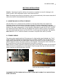
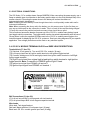
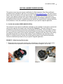
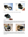
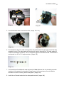
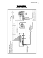
G3i INSTALLATION
TABLE OF CONTENTS
Section 1 INTRODUCTION
• 1.1 OVERVIEW
• 1.2 BENEFITS OF THE G3I SERIES – SC-E SYSTEM
• 1.3 SPECIFICATIONS
Section 2 INSTALLATIONS
• 2.1 MOUNTING AND LOCATION OF MODULE
• 2.2 PRIMARY WIRING
• 2.3 ELECTRICAL CONNECTIONS
• 2.4 G3i SC4 MODULE TERMINAL BLOCK and WIRE LEAD DESCRIPTION
• 2.5 CONNECTING SC4 MODULE TO E/PMAG IGNITION
• 2.6 MAGNETO MODIFICATIONS
• 2.7 CONNECTING TO MAGNETO
• 2.8 MAGNETO TIMING
• 2.9 SPARK PLUGS and WIRES
Section 3 MAGNETO MODIFICATIONS
•
•
3.1 SLICK 4000 & 6000 SERIES MODIFICATIONS
BENDIX 2-10, S-200, 1200 SERIES (see website for pdf download)
Section 4 OPERATIONAL TESTING
•
•
•
•
4.1 START UP
4.2 IGNITION SWITCH POSITION and MODE OPERATION
4.3 RUN-UP TESTING
4.4 IN-FLIGHT TESTING
Section 5 HAND STARTING
•
5.1 NON-STARTER EQUIPPED AIRCRAFT APPLICATION
Section 6 TACHOMETERS
•
6.1 TACHOMETER SIGNAL
Section 7 TROUBLESHOOTING
•
•
•
7.1 P-LEADS TO MAGNETO
7.2 IGNITION COIL LEADS TO MAGNETO
7.3 RADIO NOISE
Section 8 DRAWINGS
•
TERMINAL CONNECTIONS
1
G3i INSTALLATION
2
PARTS LIST
Generation 3 Ignition, G3i Series- SC-E module kit contains the following items to convert and
connect the left magneto and right E/PMag electronic ignition to the Series- SC-E module.
(1) G3i Series- SC-E installation Manual
(1) G3i Module Series- SC-E
(1) RG400 coax cables 6ft length, BNC terminated (Coil Lead, Left) (C1)
(1) 18-awg shielded P-Lead 6ft length, BNC terminated (P-Lead input/output, Left) (C2)
(1) Terminal Strip Hardware
(1) Magneto Modification Coil Terminal Stud Hardware kit
(1) Toggle Switch SPST On/Off & LED
(1) Complete packing list of itemized terminal hardware
Additional components and services available
________________________________________________________________________
G3i INSTALLATION
3
SECTION 1 INTRODUCTION
This manual covers the installation of the Generation 3 Ignition ( Series- SC-E) system. It also
covers the interface modifications of the Slick magneto. Bendix magneto modification instructions
available to view and print @ www.g3ignition.com . Included is an overview of the concept and
design philosophy, installation instructions, testing procedures, troubleshooting guidelines, and the
repair and warranty instructions for these systems. Generation 3 Ignition system Series- SC-E are
designed to interface with one magneto with an E/PMAG ignition on home built experimental
aircraft.
1.1 OVERVIEW:
Generation 3 Ignition is the first add-on, interfaced-based electronic ignition control system. The G3i
system interfaces with most Slick & Bendix aircraft magnetos. The G3i system provides redundant
magneto based ignition as a backup in case of electrical power outages or electronic ignition failure.
The G3i Series- SC-E system interfaces aircraft magnetos with electronic multiple sparking
technology ignition system. When active, the G3i module controls the magneto to produce a series
of sparks during each firing event, which lasts for 20° of crankshaft rotation to insure complete
combustion. The result is reduced variations in burn times and therefore more engine power, better
throttle response, easier starting and better fuel economy.
The G3i Series- SC-E module combines the 1 magneto, and 1 E/PMAG ignition system with all the
benefits of a dual synchronized, variable timing electronic controlled ignition system with still
retaining 1 magneto for back up. When the G3i SC-E module is activated, it receives the signals
from the existing E/PMAG primary side of the ignition. The E/PMAG timing signal is picked up by
the G3i SC-E module and tracks this information, processes it and sends primary spark energy to
excite the left magneto coil to fire in perfect synchronization with the E/PMAG’s variable timing
advance curve.
When the G3i SC-E system is turned off or looses its 12-volt power, the G3i SC-E module switches
to default (no required power) and disconnects internally from the E/PMAG’s primary signals and
reverts the magneto back to its normal, original configuration. In case of G3i SC-E EI failure, the
G3i SC-E system is turned off to revert back to magneto mode. In case of an electronic failure and
no output from the E/PMAG, the G3i SC-E will run the left magneto in electronic mode or normal
magneto mode from the contact points in the magneto at the fixed timing event
There are various starting modes, The G3i SC-E can serve as the primary ignition or the slave
ignition during start up, by using the lag timing signal from the magneto points or the retarded start
signal from the E/PMAG, thus taking advantage of a dual sync. firing with the G3i SC-E Amplified
Multiple Spark during cranking.
1.2 BENEFITS OF THE G3I SERIES – SC-E SYSTEM:
On start up, the G3i SC-E module will receive the signal from the magneto contact points or
E/PMAG starting retard program. The G3i SC-E module will automatically excite the ignition to
serve as a hot multiple spark discharge to the Left magneto at 20° of crankshaft rotation while
cranking. There are different start up and retard signal configurations to choose from. After the start
up, there will instantly be a much smoother idle with the systems on. Both EI ignition systems will
fire together in perfect sync. E/PMAG is now the primary ignition signal. Accessory case gear lash
between ignitions, or slightly miss-timed ignitions do not effect the synchronization. Fuel
G3i INSTALLATION
4
consumption will be reduced; starting will be much easier, whether hot or cold, or with fuel-fowled
plugs. You’ll see overall smoother engine operation, faster climb rates, less carbon build up in the
cylinders and on the valves, plus better compression percentages. Spark plugs will burn much
cleaner and be less susceptible to fouling. Additionally, there will be almost no magneto contact set
(points) wear.
The G3i SC-E module can be activated by toggle switch. When powered up, the original functions
of the aircraft ignition switching, key style or toggles, there functions are not affected. The original
switching will still control the left and right ignition operation. The G3i SC-E module power toggle
can be turned on and off in flight. With the engine loaded and speeds above 1500 rpm’s, switching
the G3i SC-E system on and off line, it is normal to have a very slight interruption as the system
switching occurs.
1.3 SPECIFICATIONS:
G3i SERIES – SC-E:
Number of cylinders (4)
Drives 1 magneto in synchronization
Aircraft ignition switching, LEFT, RIGHT, BOTH, START
Signal: E/PMAG ignition, Magneto contact set (points)
Optional starting inputs
Operating voltage: 9 –18 VDC, Negative ground
Current requirements: .9 AMPS/1000RPM
Recommended operating temperature: -40°f - +185°f.
Weight and size 3.1 LBS. Foot Print 8.625”L x 5.0”W x 2.25”H
G3i INSTALLATION
5
SECTION 2 INSTALLATIONS
Caution: Operating the ignition without all connections completed can result in damage to the
ignition system, other components and/or cause electrical shock.
Note: Connecting power directly to the battery or the cold (switched side) of the master solenoid will
reduce the chance of instrumentation/radio interference.
2.1 MOUNTING AND LOCATION OF MODULE:
The G3i Series- SC-E module can be mounted in a clean dry place away from engine heat.
Preferably located on the backside of the engine firewall. For engine compartment mounting,
connections of the G3i SC-E module should be orientated to the side or facing down. Depending on
location in the engine compartment, a cover should be fabricated to protect the G3i SC-E module
from water and solvents. Blast tubes can be added and routed for cooling concerns if necessary.
The color-coded leads that come out of the G3i SC-E module connect as depicted in the drawing.
Note: Maintain a 6” to 8” minimum distance of modules or amplifier from radios if possible.
2.2 PRIMARY WIRING:
The primary wires supplied with the G3i system are of a high quality aircraft shielded wire. The PLead is a shielded 18-gage and the primary ignition coil lead is a RG400 coax. All leads are 6ft in
length and are supplied with an installed BNC connection at one end. You will cut these to your
specific lengths to route to the proper location on the magneto. Then strip the center conductor for
the ring terminal and fold back the braided shield to provide as a ground.
Note: If there is a need to extend the shield ground, slide on the solder heat shrink over the braided
shield and install an extended ground wire pigtail. Crimp the proper size ring end terminals to the
center conductor and shield ground on the lead.
Leads connected to SC-E module.
Magneto ring terminal connections soldered-heatshrink with the shielded ground pigtail.
WARNING
DISCONNECT BATTERY DURING INSTALLATION TO AVOID ANY POSSIBILITY OF AN ELECTRICAL
SHORT OR SHOCK.
G3i INSTALLATION
6
2.3 ELECTRICAL CONNECTIONS:
The G3i Series– SC-E module draws .9amps/1000RPM. When connecting the power supply, use a
5amp re-settable type circuit breaker to the battery positive side or to the cold (switched side) of the
master solenoid. Connecting the power close to the battery will reduce the chance of
instrumentation/radio interference.
Note: Powering the main Battery Power through the avionics could possibly create radio and/or
instrument interference.
Note: When connecting the heavy red to the battery or a hot power source for the first time you
may see an initial spark as the connection is made. This is a result of the cap filter being charged.
To verify this remove the positive lead and reconnect, there should be no spark.
This is continued across the breaker for power up of the G3i SC-E module heavy battery inputs
(and toggle switch) connections. The toggle switch can be also wired independently with the use of
18-awg wires. Locate the supplied LED/lamp next to the G3i SC-E module power toggle or the
instrument panel for displaying the G3i SC-E system on. See input wiring diagrams for your specific
application. Over voltage protection must be used on any electrical system.
2.4 G3i SC-E MODULE TERMINAL BLOCK and WIRE LEAD DESCRIPTIONS:
Terminal block (T1 thru T6):
(T1) Switched 12-volt power in. Turn on/off G3i SC-E module (18-awg)
(T2) Left input p-lead from left ignition switch terminal or left ignition toggle terminal.
(T3) Common shield ground for left and right p-leads from ignition switch terminal or Left/Right
ignition toggle terminals.
(T4) Right in-put p-lead from original right p-lead ignition switch terminal or right ignition
toggle terminal. Note: Connection to P/EMAG ignition Right P-Lead.
(T5) Ignition input signal from E/PMAG coil terminal 3
(T6) Ignition input signal from E/PMAG coil terminal 1
G3i Series –SC-E Module decal legend
BNC Connections (C1 thru C5):
(C1) Left coil out-put BNC to left magneto coil stud terminal.
(C2) Left p-lead output BNC to left magneto capacitor terminal.
Wire Leads:
White lead: Tach signal lead out.
Red lead: Master switched 12-volt power input (16-awg).
Black lead: G3i SC-E module ground input lead (16-awg).
G3i INSTALLATION
7
2.5 CONNECTING SC-E TO E/PMAG IGNITION:
The 2 ignition input signal leads connect to the G3i SC-E, terminals T5 and T6. This will connect to
the exposed E/PMAG’s coil lead terminals on the smaller terminal block. Connections at #1 and #3
as viewed from the top. Loosen wire terminal setscrew cage that retains these primary coil leads
and insert the G3i SC-E connection signal wires underneath the coil leads into the cavity as shown.
Terminal T4 on the G3i SC-E needs a right P-Lead switched connection. This can be connected at
the right ignition switch/toggle or connect at E/PMAG’s larger terminal block at connection #4 as
viewed from the top. (Drawing1)
SC-E leads connected to E/PMAG
2.6 MAGNETO MODIFICATIONS:
These following modifications must be done with good useable working magneto. If the magneto is
in need of a rebuild or need disassembly inspection repair, then this must be done first before
installing with the Generation 3 Ignition system. Magneto modifications, ignition parts and service
are all available though Generation 3 Ignition if needed.
Before any work is done on the magneto, determine the existing magneto timing and make
reference/ and correct to factory spec. when re-installing. Depending on the type of magneto you
have and obstructions to work around, this may require the removal of the magnetos to do the
modification properly. Before the magneto is removed, take a good look at the amount of space
around the magneto. Plan the location of the ignition coil drive stud before installing it to prevent
interference with any existing engine accessories.
A qualified technician familiar with aircraft ignition systems should /can be consulted to do this
modification. Follow the modification procedures for your specific magneto application. See
illustrations (Section 3).
2.7 CONNECTING TO MAGNETO:
The left ignition P-lead is removed from the original magneto connection and now routed to terminal
2 location on the G3i SC-E module terminal strip connection. The new BNC white shielded P-lead
supplied with the BNC connector is now routed back to the left magneto P-lead connections along
with the RG400 coax cable to the coil driver stud on the magneto. The primary ignition wires/coax
can be routed together. These are not affected by other engine wiring. See Section 8 for the most
common applications and drawings. Note: See www.g3ignition.com for more specific applications.
G3i INSTALLATION
8
2.8 MAGNETO TIMING:
After the magneto has been re-installed, and with the spark plugs removed, switch the G3i
SC-E system to OFF and the magneto switched to hot. The magneto can be re-timed as in
a normal configuration with a dual magneto synchronizer timing light tweeter. Follow your
engine manufacturer’s factory timing specifications.
2.9 SPARK PLUGS AND WIRES:
Original aircraft ignition harness and spark plugs can be used with the G3i SC-E ignition. The
aircraft ignition harness (spark plug wire) is a solid core, and is designed with a high quality outer
shielding with very minimal electro magnetic interference (EMI). This will not interfere with the
operation of the G3i SC-E module. The magneto ignition harness cap can be modified to accept
automotive leads (view and print under Magneto Modifications @ www.g3ignition.com. Which will
allow a wide range of spark plug boots and terminal ends and automotive type spark plugs with
inserts. It is recommended to follow the spark plug manufacture’s specification for spark plug gaps.
The most common total spark plug air gap is increased to .020” to .026” depending on the spark
plug type and compression ratio.
________________________________________________________________________
G3i INSTALLATION
9
SECTION 3 MAGNETO MODIFICATIONS
This section covers the most common modification for Slick magnetos. Other Slick and Bendix
modifications are avialiable in pdf form to view and print @ www.g3ignition.com. The main factor to
keep in mind is the location of the coil terminal stud. Prevent any chance of the terminal grounding
out on/in the magneto housing and/or other magneto components. Keep all wires clear of any
rotating parts and where there is any chance of wire chafing. The following modification examples
are performed off the aircraft. A qualified technician familiar with aircraft ignition systems should do
this modification. Follow the modification procedures for your specific magneto application.
3.1 SLICK 4000 & 6000 SERIES MODIFICATION:
This section the most common modification examples on the installation of the ignition coil terminal
stud into the magneto the magneto main housing side. Example 1: The main housing side
modification will not require coil lead wire to be lengthened or modified. The main factor to keep in
mind is to locate the coil terminal stud and terminals away from any chance of grounding out on/in
the magneto housing and/or other magneto components. Keep all wires keep clear of any rotating
parts and where there is a chance of wire chafing. These modifications are performed off the
aircraft. A qualified technician familiar with aircraft ignition systems should do this modification.
Follow the modification procedures for your specific magneto application.
EXAMPLE 1: Main Housing Side location
1. Remove the top cover to gain access to the coil lead that is connected to the contact points.
Remove both the capacitor and coil leads from the contacts. (Image 1d, 2d, 3d, 4d)
Image 1d
Image 2d
G3i INSTALLATION 10
Image 3d
Image 4
2. It will be necessary to remove the distributor cap/rotor assembly. (Image 5d)
Image 5d
3. For reference and showing the general area of the lower part of the main magneto housing. This
is the area where the ignition coil terminal stud will be located. The depth to the casting shelf
measurement is 1.00”. The distance from the casting step to the center of the distributor cap
screw hole is also 1.00”. (Image 6d, 7d)
Image 6d
Image 7
4. The preferred location of the new coil terminal stud will be here. Note: The indexed center
punch mark for drilling. The distance shown from the center of the distributor cap screw hole is
.625”. Also the distance from the top face is .625” Center punch and drill a hole sized to .250”
(Image 8d, 9d)
G3i INSTALLATION 11
Image 8d
Image 9d
5. An outside/inside view of terminal location. (Image 10d, 11d)
Image 10d
Image 11d
6. The hardware is layout in order for the ignition coil terminal stud into the lower part of the main
magneto housing. The male spade stud terminal will need to be modified. The male spade will
need to be trimmed to a width of .187” to accept the original coil female terminal. Then bend the
male spade to a 20° to 30 ° angle as shown. (Image 12d)
Image 12d
7. Coil terminal stud installed with male flag terminal. Note: Between the two insulating shoulder
washers at the magneto housing place a small amount of two-part epoxy for extra rotation
resistance on stud. Just snug, do not final tighten. (Image 13d)
8. Install the coil female terminal to the male spade terminal. (Image 14d)
G3i INSTALLATION 12
Image 13d
Image 14d
9. Rotate the connected coil terminals to the 3 o’clock position, gently routing the coil wire into a
small loop. (Image 15d)
10. Now finish tightening the coil terminal stud assembly. Tighten to 20 - 25 in.-lbs. (Image 16d)
Image 15d
Image 16
11. Re-install the index distributor cap/rotor assembly to the shaft gear. Note: If a Slick timing pin is
not available, a #42 or .093” drill bit will do. Torque distributor cap screws to 18-28 in.-lbs.
(Image 17d)
12. Re-connect the capacitor lead to the contact set. This will be the only connection to the contact
set. Note: Clean magneto housing of all drill chips and any type of contamination with
compressed air before reassembly. Install top cover housing screws, torque to 18-28 in.-lbs
ready to install. (Image 18d)
Image 17d
Image 18d
G3i INSTALLATION 13
SECTION 4 OPERATIONAL TESTING
Before starting, insure the wiring is securely fastened, and the G3i SC-E module is mounted
securely and are in an area free of transmitted engine vibration. Check all routing and make sure
leads are away from any chafing and exhaust heat.
4.1 START UP:
With the system connected and master switch on, G3i SC-E system toggle switched on, the green
LED/lamp will illuminate. This will show that the SC-E module is active when in start mode powering
up the left magneto. This will provide the left magneto in proper retard time signal from the E/PMAG
with a multiple discharge spark during startup. The G3i SC-E module power toggle can be off when
starting. If the G3i SC-E toggle is off while starting, the ignition system will revert back to the normal
magneto mode. The engine will continue to run the left magneto as normal. At this time you can
switch the G3i SC-E module on to receive the timing signal from E/PMAG to bring the magneto into
timing sync.
4.2 POSITION AND MODE OPERATAION:
(POWER SWITCH)
(____________IGNITION SWITCH___________)
SC-E E/PMAG
ON
ON
ON
OFF
OFF ON
ON
ON
ON
ON
ON
ON
OFF OFF or ON
RIGHT
LEFT
BOTH
OFF
ON
OFF
ON
ON
OFF
ON
START
ON
ON
ON
NOTE*
(1)
(2)
(3)
(4)
(5)
(6)
(7)
*NOTE:
(1) In start mode, the SC-E module will read and use the right E/PMAG retard signal to fire the mag
in sync. with multiple spark discharge while cranking/starting.
(2) In start mode, the SC-E module will default to the signal from the left magneto contacts and fire
with multiple spark discharge while cranking/starting. Left magneto should have a retard impulse
coupler. Ignition switch jumped at “R”or “1” terminal to ground right p-lead while cranking to disable
right E/PMAG in start mode only.
(3) In start mode, left magneto operation is in normal mode. Not excited from the SC-E module.
(4) SC-E module is tracking right E/PMAG’s timing curve and firing the left mag in sync. with right
E/PMAG.
(5) SC-E module defaults to reading the left magneto’s contacts to continue to fire the left mag. in EI
at the mag’s fixed timing. Right E/PMAG is not firing.
(6) Left side ignition disabled. Ignition drop during run up.
(7) Left magneto is in normal magneto mode, No EI.
G3i INSTALLATION 14
4.3 RUN-UP TESTING:
After the start up, there will instantly be a much smoother idle with the system on. Both ignitions are
firing together in perfect synchronization. With the G3i SC-E system on during run up, go to the
suggested specific rpm for setting the mixture and continue with the normal ignition cycling from
both, left, right, checking for rpm drop. If the fuel mixture is near optimum, there will be much less
rpm drop and the exhaust note will not sound as lazy. Next switch the G3i SC-E system off and
repeat the ignition cycle, both, left, right, in normal magneto mode. Remember this is the back up
mode.
4.4 IN-FLIGHT TESTING:
The G3i SC-E system can be turned on and off, and cycled left and right in flight. Turning off the
system will verify that the magneto is still functioning in the normal back up mode. When the G3i
SC-E system is coming back on line it is normal to have a very slight rpm interruption as the system
is powered up in the higher rpm range. Lean as normal as suggested by your engine manufacture
settings. Verify that all cylinder head temperatures are within normal operating limits.
NOTE:
In flight loss of engine power from suspected G3i SC-E ignition system failure, Toggle off
the power to the G3i SC-E ignition system to revert back to default magneto mode.
________________________________________________________________________
G3i INSTALLATION 15
SECTION 5 HAND STARTING
5.1 HAND STARTING
Do not attempt to hand prop start your engine. Do this only if you are completely trained and
competent with hand prop starting procedures. The following is not a complete thorough
guide or recommendation on how to safely hand prop start your engine.
Hand starting is to be used if your non-starter equipped or the battery is low and you’re not able to
crank the engine. By using proper safe hand starting procedures. If the left magneto is a retard lag
impulse-coupling magneto, hand prop starting can be performed in a safe normal manner with the
G3i SC-E system off. Using the left magneto for starting.
WARNING:
Never turn the engine backwards with the magneto and the G3i SC-E system hot!
The G3i SC-E module will see the pulse signal from the magneto trigger points and fire the
magneto resulting in a backfire and causing severe injury!
WARNING:
Initial spark can occur when the G3i SC-E module is turned ON and powers up. This can
result in a backfire and the of severe injury. Always remain clear of the propeller when
turning on the G3i SC-E module.
WARNING:
Always turn on the G3i SC-E module FIRST, then left magneto switch to on.
An initial spark can occur when the G3i SC-E module is turned ON and powers up. Resulting
in a backfire and possibility of severe injury. Always remain clear of the propeller when
turning on the G3i system.
WARNING:
E/PMAG EMERGENCY PROP STARTING:
Follow the Hand Prop Starting Guidelines as lineout in the E/PMag user manual under
“EMERGENCY PROP STARTING”
Follow all hand starting safety procedures when hand starting. Leave the ignition switches OFF
and G3i SC-E module OFF and E/PMAG OFF until when ready to pull through the compression
stoke to start. Always remain clear of the propeller when turning on the G3i SC-E module.
Otherwise all switches remain off until ready. The G3i SC-E module will read the E/PMAG ignition
signal when hand prop starting and fire the magneto. IMPORTNT to still taking precautionary
measures for starting at anytime.
________________________________________________________________________
G3i INSTALLATION 16
SECTION 6 TACHOMETERS:
6.1 TACHOMETER SIGNAL
Tachometer signal supplied from the G3i SC-E module is a clean 12-volt, square wave signal with a
20% duty cycle. This reference signal is produced with every firing event. NOTE: The magneto plead should never be connected to the G3i SC-E tachometer signal out-put terminal. DAMAGE
WILL RESULT to the G3i SC-E. After completing the installation of the G3i system, when turned on
the digital tachometer reading will usually display twice the engine rpm. Most late model engine
instrumentation with digital tachometers are set up for magnetos and read every other firing event.
This usually can be reprogrammed to accept this every fire event reference signal to get the correct
rpm reading for your digital tachometer. Refer to your install manual or contact your specific enginemonitoring manufacturer for reprogramming procedures. A good alternative for providing an isolated
“pip/tach” signal to digital tachometers is the UMA (T1A9) or (1A3-4) sending unit for tachometers.
These sensors screw into the existing magneto (Slick or Bendix) side vent hole or tach cable drive.
We will do our best to provide tachometer troubleshooting and/or customer support on this topic.
________________________________________________________________________
G3i INSTALLATION 17
SECTION 7 TROUBLESHOOTING:
All Generation 3 Ignition systems and components undergo a series of functional tests prior to
delivery. The G3i modules are dyno tested from 25 to 3600 crankshaft rpm with magnetos and a
G3i SC-E module in all modes to ensure proper operation. If you have any question concerning
your G3i ignition system, do not hesitate, please contact our tech support at 303-806-5120, or via
email [email protected] Monday thru Friday 7am – 3pm Mountain Time.
The most common installation failures are the incorrect connection of the BNC C-terminals on the
G3i module and the signal P-leads and/or ignition coil terminal leads. Double check the wiring
diagram and insure proper connection locations.
7.1 P-LEADS TO MAGNETO:
All P-lead and ignition coil terminal leads can be checked with the use of an ohmmeter when
disconnected at both ends. The BNC center conductor will show no conductivity to the outer shield.
Also on the center conductor of each lead from one to the other will have very little to no resistance.
P-lead center conductor from the magnetos will have continuity to ground when the points are
closed and no continuity when the points are open.
7.2 IGNITION COIL LEADS TO MAGNETO:
Ignition coil lead center conductor from the magnetos will have .4 to 1.0 ohm continuity (this will
vary on type of magneto) to ground at all times through the coil primary windings when connected
to the magneto. If this shows open, first check the ignition coil lead for open. If the lead checks out
ok, then test at the coil terminal stud to ground to see if the open is there. Then there is an open
between the coil terminal stud and primary lead to the coil inside the magneto.
Verify ignition coil lead grounded at all times. Check lead first for continuity to the shield. This will be
open. Next check coil stud terminal to ground, if grounded, there is improper stud installation.
7.3 RADIO NOISE:
If there is radio interference and/or erroneous engine monitoring discrepancies that go away when
the G3i system is turn off.
Possible causes of electrical interference and the necessary corrections.
1. Powering the system through the avionics bus will create interference. Relocate the main power
input leads and G3i SC-E module switched in power (terminal 1) to battery or to the switched side
of the master solenoid. The positive must be run through a circuit breaker!
2. Both power and grounds should come from the battery or nearby source.
3. Check all ground connections.
4. Check all secondary ignition leads (spark plug wires) for fraying and/or loose connections.
________________________________________________________________________
G3i INSTALLATION 18
SECTION 8 DRAWINGS:
TERMINAL CONNECTIONS:
NOTICE
Generation 3 Ignition systems must be installed with good useable working magnetos. If the
magnetos are in need of a rebuild or need disassembly inspection repair, then this must be done
first, before installing the G3ignition system.
Magneto modifications, ignition parts sales and service are available though Generation 3 Ignition if
requested.
WARNING
Failure of the G3i ignition system or products, or improper installation of the G3i ignition systems or
products, may create a risk of property damage, severe personal injury or death.
WARRANTY and LIMITATION OF LIABILITY
Generation 3 Ignition systems are warranted to the original purchaser for one full year from the date
of purchase against defects in material and workmanship. During this period, Generation 3 Ignition
will repair or replace G3i modules within the warranty period that, in Generation 3 Ignition’s sole
opinion, that have not been subjected to abuse or any attempted field repairs. This warranty is
limited to the purchase price of Generation 3 Ignition hardware and does not cover the engine or
other engine components that may be affected by defects or failure of the system, and Generation 3
Ignition shall not be liable for any obligations or liabilities whatsoever, or any strict liability theory.
Generation 3 Ignition hardware is intended only for installation and use on experimental aircraft,
which are licensed by the FAA in the “EXPERIMENTAL” category pursuant to a Special
Airworthiness Certificate. All products must be installed and used in accordance with the current
installation manual by experienced mechanics. The most current installation instructions are
available from Generation 3 Ignition which are on the website at www.g3ignition.com
RETURNS
You can return any new or unused item within 30 days of the date your item was shipped and we
will refund the full purchase price if received in re-saleable condition. Complete with instructions and
all components (if applicable). Certain items may not be eligible for return (e.g. custom fabricated
and /or special ordered items, labor charges, etc). Provide a copy of the original order showing the
purchase information and date of purchase. Also provide a brief explanation for the return. An
administration, restocking charge may be applicable to all merchandise returned to cover costs
involved in processing the return. Please call first for return authorization and instructions.
For further information on our products, contact us via e-mail at [email protected]
Generation 3 Ignition
2331 W. Hampden Ave. Suite 130
Englewood. CO. 80110
Phone: (303) 806-5120
Copyright © 2010, Generation 3 Ignition LLC, All rights reserved.
Revised 06.01.2010
All trademarks and copyrights referred to herein are used solely for identification or description to provide reference within this manual.
Unless expressly stated, Generation 3 Ignition is not affiliated with any company, or owner of a trademark or copyright identified herein of
Slick, Bendix, E-Mag Ignition. And makes no statements, express or implied, concerning use of any trademarked or copyrighted product
or service. All registered trademarks and copyrights are the property of their respective owners.