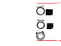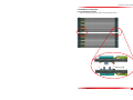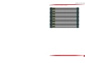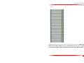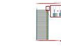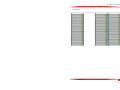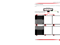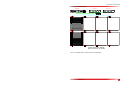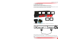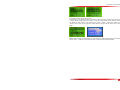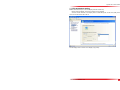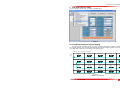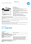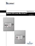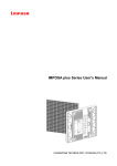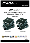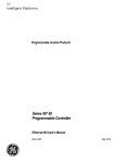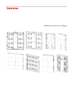
1
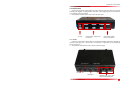
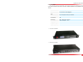
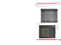
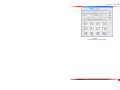
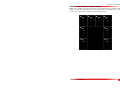
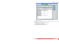
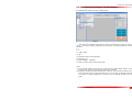
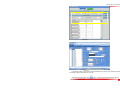
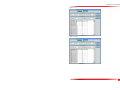
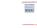
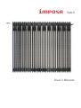
User’s Manual
Imposa Velo V User’s Manual
Content
1 Tile introduction....................................................................................................................................................4
1.1 Specification.................................................................................................................................................4
1.2 Components introduction...........................................................................................................................6
1.2.1 Power box......................................................................................................................................... 6
1.2.2 Hub box(HUB).............................................................................................................................6
1.2.3 VPU2000...........................................................................................................................................7
1.2.4 Bar Tiles............................................................................................................................................ 8
1.2.5 Cables................................................................................................................................................9
1.3 Hardware connection............................................................................................................................... 12
1.3.1 Tiles connection............................................................................................................................. 12
1.3.2 Power connection..........................................................................................................................17
1.3.3 Signal connection.......................................................................................................................... 20
1.4 VPU2000 connection............................................................................................................................... 20
1.5 PC Parameters setting.............................................................................................................................22
2 LDU2000 software setting............................................................................................................................... 24
2.1 Coordinate setting of regular display.....................................................................................................24
2.2 Coordinate setting of irregular display.................................................................................................. 27
2.3 Installation and setting for irregular display..........................................................................................29
2.4 Brightness adjustment............................................................................................................................. 34
2.5 Color temperature adjustment................................................................................................................ 34
File NO. WI/CZ-PM-M0001 Ver1.0
2
Imposa Velo V User’s Manual
Update record
Version
Modified content
modifier
Modified time
Ver1.0
First version
WJF、ZWJ
2013-08-01
File NO. WI/CZ-PM-M0001 Ver1.0
3
Imposa Velo V User’s Manual
1 Tile introduction
1.1 Specification
File NO. WI/CZ-PM-M0001 Ver1.0
4
Imposa Velo V User’s Manual
Model
VFO31.25
VFO62.5
VFO31.25
VFO62.5
Pixel Pitch
31.25mm
62.5mm
31.25mm
62.5mm
Pixel Configuration
1R1G1B
1R1G1B
3X32
2X24
3 in 1 SMD
3 in 1 SMD
Strip Information
Resolution of Strip (pixel)
(HXW)
Size of Strip (mm)(HXWXD)
77.4x1000x46.9
3X32
2X24
77.4x1500x46.9 77.4x1000x36.4 77.4x1500x36.4
Module Information
Resolution of Module(pixel)
(HXW)
Size of Module(mm)(HXWXD)
36X32
20X24
36X32
20X24
1125x1000x46.9 1250x1500x46.9 1125x1000x36.4 1250x1500x36.4
Display Information
Power Consumption (W/㎡)
Brightness(cd/㎡)
Viewing Angle
IP Rate
70
280
70
>6000
>1500
>2000
>1000
120°/120°
80°/80°
110°/ 50°
IP66
Grey Level
16 bit Per Color
Frame Frequency(Hz)
Refresh Frequency(Hz)
Brightness
280
Control
Nominal LED Working Life
File NO. WI/CZ-PM-M0001 Ver1.0
>60
>3000
100
Up to 100,000 Hours
5
Imposa Velo V User’s Manual
1.2 Components instruction
1.2.1 Power box
Power boxes provide the curtain display with power. Inside the power box, there are 3 48V/1000W
switching power supplies. It’s equipped with 4 output ports, 3 ports supplying power for LED bar tiles and
1 port supplying power for hub boxes.
Size (LXWLD): 520x500x120mm. Size is shown as below figure.
AC Input
DC48V Output. Supply power
for bar tiles.
DC5V Output. Supply
power for hub boxes.
1.2.2 Hub box
Hub box is a device used to receive data from LDU2000 and distribute these data to all display tiles.
There are 4 data output ports, 1 DC input port, 1 DC output port, 1 Signal input port and 1 Signal output
port for each hub box.
Size (LXWXD): 240x150x70mm. Size is shown as the below figure.
DC Output, 5V
Signal Output
DC Input,5V
Signal Input
Displaying data output ports,
connected with display tiles.
File NO. WI/CZ-PM-M0001 Ver1.0
6
Imposa Velo V User’s Manual
1.2.3 VPU2000
VPU is the main control for curtain display, which is used to transfer the PC displaying content into
specific data and deliver these data to hub boxes. Detailed specifications and parameters are as
followed.
Item
Parameters and specifications
Input
DVI signals
Max. Resolution:1920x1080@60Hz
Output
2 RJ45 ports
Max. control pixels of each port: 1920x340
Max. control pixels
1920x680
Communication
USB
Power supply
Input:100-240 VAC, 50-60 Hz
Power consumption: 10 W
Working temperature
-20~60 ℃
Working Humidity
0-95%
Size(WxHxD)
483x59x333 mm
Front view of VPU2000
Rear view of VPU2000
File NO. WI/CZ-PM-M0001 Ver1.0
7
Imposa Velo V User’s Manual
1.2.4 Bar tiles
A bar tile is the displaying unit of curtain display, which consists of 10 or 12 strips, as the following
figure shows.
Front view of one bar tile (12 strips)
Rear view of one bar tile (12 strips)
File NO. WI/CZ-PM-M0001 Ver1.0
8
Imposa Velo V User’s Manual
Curtain display enjoys great flexibility. It can be rolled up to move it, as the following figure shows.
Connector of bar tiles adopts the design of data and power sharing one connector, as the following
figure shows.
Power input connector of bar data
Power output connector of bar data
1.2.5 Cables
Two-in-one joint cable
File NO. WI/CZ-PM-M0001 Ver1.0
9
Imposa Velo V User’s Manual
Power cable
Data cable
Signal cable
File NO. WI/CZ-PM-M0001 Ver1.0
10
Imposa Velo V User’s Manual
Connection of cables
Bar tile
Power box
Two-in-one
joint cable
Power cable
Data cable
Hub
VPU2000
Signal cable
File NO. WI/CZ-PM-M0001 Ver1.0
HUB
11
Imposa Velo V User’s Manual
1.3 Hardware connection
1.3.1 Connection of tiles
Strips are connected by chain pin shafts, as the below figure shows.
File NO. WI/CZ-PM-M0001 Ver1.0
12
Imposa Velo V User’s Manual
Drawing of one tile when bar connection is finished:
File NO. WI/CZ-PM-M0001 Ver1.0
13
Imposa Velo V User’s Manual
Connect the tiles into one column in the same way. Number of tiles is subject to the real display
pixels.
But signal
cables and power cables are not connected one by one in series.
Connection of signal cables and power cables will be introduced later.
Special note: Above figures show how to connect tiles in series with chain pin shafts.
File NO. WI/CZ-PM-M0001 Ver1.0
14
Imposa Velo V User’s Manual
Hang and install the display with chain pin shafts and chain hooks, as the following figure shows.
File NO. WI/CZ-PM-M0001 Ver1.0
15
Imposa Velo V User’s Manual
Hang and install all columns of tiles one by one. Drawing of the whole display is shown as the
following figure.
。
。。 。。。
File NO. WI/CZ-PM-M0001 Ver1.0
16
Imposa Velo V User’s Manual
1.3.2 Power connection
One power box can be connected to 6 tiles. There are two connecting ways, as the following figure
shows.
Power supply
Output:48V DC
1 P ort: 20A Max. / Tota l:30A Max.
Output:4 8V DC
1 Po rt:20A Max. / Total:30A Max.
Output:48V DC
1 Port:20A Max. / Total:30A Max.
Output: 48V DC
To Hub
P1
AC IN
P2
P3
To hub box
Curtain screen unit quantity that
one power supply box can control
File NO. WI/CZ-PM-M0001 Ver1.0
17
Curtain screen unit quantity that
one power supply box can control
AC IN
Output:48V DC
P1
P2
1 Port:20A Max. / Total:30A Max.
Output: 48V DC
P3
1 Port:20A Max. / Total:30A Max.
Output: 48V DC
Power supply
1 Port:20A Max. / Total:30A Max.
To Hub
Output:48V DC
To hub box
Imposa Velo V User’s Manual
File NO. WI/CZ-PM-M0001 Ver1.0
18
Imposa Velo V User’s Manual
1.3.3 Signal connection
VPU2000
hub box 1
AC INPUT
100~240V
DC IN
CUBS2(PB)
CUBS1
CUBS3(Pr)
CUBS4(Y)
DC OUT
Signal input
Signal output
Port 1
hub box 2
Port 2
DC IN
DC OUT
Signal input
Signal output
Port 1
Port 2
。。。
USB
Port 1
DVI output
DVI i nput
Port 2
ETH
Signal output
USB
DVI-OUTPUT
DVI
DVI / HDMI / VGA
INPUT
Port 3
Port 4
Port 3
Port 4
Signal output
Signal input
Curtain screen unit quantity
that one hub box can control
(Notes: For detailed pictures, please refer to the attached files)
File NO. WI/CZ-PM-M0001 Ver1.0
19
Imposa Velo V User’s Manual
1. 4 VPU2000 connection
Connect PC to VPU with DVI cable(connector 4);
Connect the connector 1 to connector 3 on VPU with another DVI cable;
Connect the VPU (connector 2) with the control box with 9 Pin D Connector;
Connect the DVD to the 4 metal ports on the right, of which CVBS signal should connect to any one of
the 4 ports, while YPRPB signal should connect to the 3 ports outermost.
Converted
signal
input (1)
Display
signal
output (2)
Computer
signal
input(4)
YPRPB
input(3)
CVBS
input(4)
Converted
signal
output(3)
AC INPUT
100~240V
The connection of VPU of synchronous playing(not include the PC and DVD part)
Port 1
DVI output
DVI input
Port 2
Signal output
ETH
USB
DVI-OUTPUT
DVI
DVI / HDMI / VGA
INPUT
CUBS2(PB)
CUBS1
CUBS3(Pr)
CUBS4(Y)
After the connection, turn on the VPU to set the video sources;
The setting steps: MENU > SELECT VIDEO > (choose the signal format of corresponding video
source)
,press the buttons to choose the right video input sources according to the connecting video
signals.
File NO. WI/CZ-PM-M0001 Ver1.0
20
Imposa Velo V User’s Manual
The setting of shortcut key of video sources
Shortcut steps: In the working interface, press “select” to enter the menu; press the button up and down
to choose “system setting” menu, press “select” to enter the system setting, choose “shortcut”, then you
can define the video sources of the shortcut keys “Video1”, “Video2”, “Video3” and “Video4” in the
“shortcut” menu. Then you can switch the current video source input with the shortcut key on control
board.
Notes: When choosing the CVBS signals, you must choose the right CVBS according to the number of
the port, that’s: connector 1 should choose CVBS1; connector 2 should choose CVBS2.
File NO. WI/CZ-PM-M0001 Ver1.0
21
Imposa Velo V User’s Manual
1. 5 PC parameters setting
Notes: We recommend you to use the display card with NVIDIA chip.
Before setting the display, connect the computer to the VPU2000.
And then set the resolution of the display card as 1920X1080 pixels, set the color quality as 32-bit
color, and set the refresh rate as 60 Hz.
Set the display mode as “same on two display (copy mode)”
File NO. WI/CZ-PM-M0001 Ver1.0
22
Imposa Velo V User’s Manual
File NO. WI/CZ-PM-M0001 Ver1.0
23
Imposa Velo V User’s Manual
2
LDU2000 software setting
Set up the software Imposa Tools,click Tool > LDU2000 Setting.
Image 2.1
2.1 Coordinate setting of regular display
The maximum pixel number a hub box can control is 128x72 (WXH). When a display is arranged
into a regular rectangle, such as display with 608X252 (WXH) pixels, distribution situation of hub boxes
and control pixels of each hub box are shown as the following figure.
Distributin of hub boxes for the whole screen(608X252)
128X72
Signal
input
DC OUT
S ig nal input
Si gnal output
hub box
P or t 1
P or t 3
P ort 2
DC IN
DC OUT
S ig nal input
Si gnal output
DC IN
DC OUT
Si gnal output
S ig nal input
Si gnal output
DC OUT
P or t 1
P or t 3
DC IN
DC OUT
S ignal n
i put
S igna l output
P ort 3
DC IN
DC OUT
P ort 4
DC IN
DC OUT
S ignal n
i put
S igna l output
S igna l input
S ig nal ou tput
Po rt 2
DC N
I
DC OUT
P ort 3
Po rt 1
Po rt 3
DC IN
DC OUT
S igna l input
S ig nal ou tput
P or t 3
DC N
I
DC OUT
P or t 4
DC IN
DC OUT
S igna l input
S ig nal ou tput
Sig nal input
S ignal output
P ort 2
DC N
I
DC OUT
P or t 3
P ort 1
P ort 3
DC N
I
DC OUT
Sig nal input
S ignal output
P or t 3
DC N
I
DC OUT
P ort 4
DC N
I
DC OUT
Sig nal input
S ignal output
S ig nal input
P or t 1
P or t 3
P ort 2
P or t4
P ort 2
P or t4
96X72
P ort 2
DC N
I
DC OUT
P or t 1
P or t 3
S ig nal input
S ignal output
P or t 1
P or t 3
P or t 4
P ort 2
P or t4
96X36
hub box
P ort 2
DC N
I
DC OUT
S ig nal input
S ignal output
P or t 1
P or t 3
P or t 4
Image 2.2
example of regular display
File NO. WI/CZ-PM-M0001 Ver1.0
S ignal output
P or t 4
128X36
hub box
Po rt 2
P or t 1
hub box
P or t 1
P or t 3
P ort 4
S ignal output
96X72
P ort 2
128X72
Po rt 2
S ig nal input
P or t 4
hub box
P or t 1
P ort 4
128X36
hub box
P or t 2
hub box
P or t 1
hub box
P ort 1
P ort 3
P or t 4
S ignal output
128X72
Po rt 2
128X72
P or t 2
Sig nal input
P ort 4
hub box
P ort 1
P or t 4
96X72
hub box
P ort 1
128X72
P or t 2
128X36
hub box
P ort 2
S ig nal ou tput
hub box
Po rt 1
Po rt 3
P ort 4
S igna l input
hub box
Po rt 1
128X72
P ort 2
128X36
hub box
DC OUT
DC IN
P or t 4
hub box
P or t 1
P or t 3
D C IN
S igna l output
Po rt 3
hub box
S ig nal input
S ignal n
i put
P ort 4
128X72
DC OUT
P or t 2
128X72
P ort 2
128X72
hub box
Po rt 1
hub box
P or t 1
P or t 3
D C IN
S igna l output
Po rt 3
hub box
DC OUT
S ignal n
i put
P ort 4
128X72
D C IN
128X72
128X72
hub box
D C IN
24
P ort 2
P or t4
Imposa Velo V User’s Manual
Signal trend is shown as the following figure.
Image 2.3
example of regular display
In this case, please set LDU2000 parameters according to the following steps.
A Input the number of the connecting controller in the Tiles Count (20)
B:Input synchronous coordinates (The input number is subject to real synchronous position. As for this
example, we should input X: 3 Y: 10 here.), and control pixels of ports (Max.1920x340)
C Input corresponding data in Row and Column according to the arrangement of controller.(Row:4
Column:5)
D Input the width and height of each controller in Tile W and Tile H (Tile W :128 Tile H:72)
E
Choose corresponding Pattern according to the connecting direction of the controllers.
F
Click Send, and send the design to LDU2000.
The parameters setting interface is shown as the following figure.
File NO. WI/CZ-PM-M0001 Ver1.0
25
Imposa Velo V User’s Manual
Image 2.4
Coordinate setting of regular display
File NO. WI/CZ-PM-M0001 Ver1.0
26
Imposa Velo V User’s Manual
2.2 Coordinate setting of irregular display
Notes: If every controller control area of different size, and the arrangement of the controllers is irregular
(Image 2.5), the software will not be able to automatically determine the coordinate X and Y of every
controller. So you need to set the coordinate of every controller manually.
X=0
Y=0
X=120
Y=0
X=240
Y=0
X=0
Y=180
X=360
Y=0
X=360
Y=180
X=0
Y=360
X=360
Y=360
Image 2.5
File NO. WI/CZ-PM-M0001 Ver1.0
27
Imposa Velo V User’s Manual
Image 2.6 coordinates setting of irregular display
The setting steps are as follow:
A Draw a picture like Image 2.5 according to the reality, adjust the coordinate X and Y of every
controller.
B Input the number of connecting controller in Tiles’ Count.
C Choose Rectangle in Tiles’ Placement.
D Input the coordinate of every controller in the table.
E Click Send, send the design to LDU2000.
File NO. WI/CZ-PM-M0001 Ver1.0
28
Imposa Velo V User’s Manual
2.3 Installation and setting for irregular display
Run iMPOSA Tools software, click Tool / LDU2000 Setting:
Image 2.7
After entering the LDU2000 setting interface, please click OPEN button to insert the setting file
(tg.cnt) which will be provide by manufacturer into the program. In AREA CONTROLLED, the setting
should be:
X:0
Y:0
W:1280 or higher
H:205
In connection setting, the setting should be:
TILES’COUNT:23
TILES’PLACEMENT:FREEDOM
For PORT1 & PORT2, setting needs to be the same
Notes:
(1) Due to irregular display’s special structure, we will show the irregular display shape by covering
some parts, that is to say, the outlying LED modules are not installed.
(2) Because of our design, the width coordinate (X) of control box, every control box’s width is set to 144
pixels, that means even the actual width pixels are not up to 144 pixels, the resolution will be taken
as 144 pixels. For height coordinate (Y) of control box, you can calculate according to the actual
pixels.
File NO. WI/CZ-PM-M0001 Ver1.0
29
Imposa Velo V User’s Manual
Image 2.8
Image 2.9
If the display position is not correct, please use iMPOSA Player software to do download the remedy
files including 23 pcs PMG pictures & tg.SYL file.
After finish downloading files, click
File NO. WI/CZ-PM-M0001 Ver1.0
button. The interface will show yellow parts with red
30
Imposa Velo V User’s Manual
frame line which is taken control box as quantity units.
Take the following picture as an example, this display is showed at the LED sign’s left hand side,
you will see the red frame is a line consist of pixels. Please count how many pixels before the red dot
and how many pixels above the red dot.
If there are 3 red pixels before the red line, the X coordinate should be input “X-3”, likewise, if there
is one pixel above the red line, the Y coordinate should be input “Y-1”.
button again to see whether the display position is correct or not. If the display
Click the
position is correct, please modify the tile address’s X & Y coordinates.
Image 2.10
Control range for 23 pcs control boxes.
After adjustment
File NO. WI/CZ-PM-M0001 Ver1.0
31
Imposa Velo V User’s Manual
Reference value (the value of X & Y in the pictures are for reference only, the actual value may be
slightly different)
PORT1(1-12)
Image 2.11
PORT1(12-23)
Image 2.12
File NO. WI/CZ-PM-M0001 Ver1.0
32
Imposa Velo V User’s Manual
PORT2(1-12)
Image 2.13
PORT2(12-23)
Image 2.14
File NO. WI/CZ-PM-M0001 Ver1.0
33
Imposa Velo V User’s Manual
2.4 Brightness adjustment
Choose Manual in Bright Mode, input the wanted brightness value in Manual Adjust, and click Send.
Image 2.15
2.5 Color temperature adjustment
First click Color Adjust and open the color temperature adjusting interface.
Image 2.16 Open the adjusting interface of color temperature
File NO. WI/CZ-PM-M0001 Ver1.0
34
Imposa Velo V User’s Manual
Drag the slider to adjust the brightness value of R,G,B, you will get the effect immediately. When
you get the effect you want, please click Save to 9300,Save to 6500, Save to Preset. And then click OK
to close the adjusting interface of color temperature. In the end, click Send in LDU Setting, and send the
adjustment to the LDU.
Image 2.17 color temperature adjustment interface
File NO. WI/CZ-PM-M0001 Ver1.0
35