1
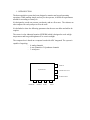
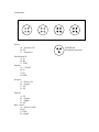
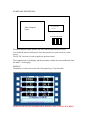
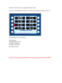
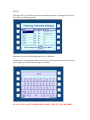
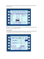
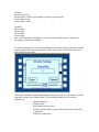
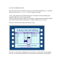
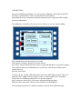
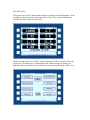
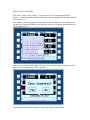
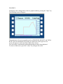
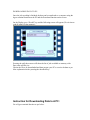
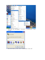
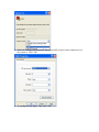
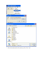
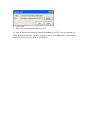
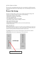
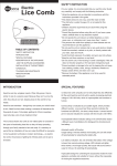
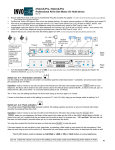
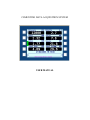
CEMENTING DATA ACQUISITION SYSTEM
USER MANUAL
TABLE OF CONTENT
1- INTRODUCTION
a. System description
b. Power connections
2- SENSORS CONFIGURATION
3- OPERATOR’S SCREEN
a. Job Set-up
b. Calibration
c. Recording
d. Graphics
e. Download data
1- INTRODUCTION:
The data acquisition system has been designed to monitor and record cementing
operations. While making simple and easy for the operator, it fulfills all requirements
needed for recording a cement j ob.
It is designed to record one pressure, one density and two flow rates. The volumes are
also computed for each pump as well as the total.
It is defaulted to show the following parameters but the user can delete and add as he
requires.
The screen is color industrial monitor QTHERM which is designed to work at high
temperatures and has good brightness to be seen in sunlight.
The computer box is based on a computer board with ADC integrated. The system is
capable of acquiring:
- 8 analog channels
- 4 rate channels or 2 Quadrature channels
- 3 serial ports
DISPLAY
Acquisition Box
DOWNLOAD TO PC
POWER SUPPLY
PRESSURE
DENSITY
RATE1
RATE2
Sensors Connection:
The system has been designed to be connected as per labels provided, mainly Pressure,
Density, Rate1 and Rate2.
The cables should not be interconnected or reversed, this my damage the computer board.
Below are the electronic specifications of each channel:
Channel 1:
Pressure (Defaulted), accepts 0 -20 mA or 4-20 mA signals. Other types of
sensors need a modification in order to use them.
This channel has a power supply for sensor of +15volts DC and a
maximum power under this voltage of 12 watts.
Channel 2:
Density (Defaulted), accepts 0 -20 mA or 4-20 mA signals. Other types of
sensors need a modification in order to use them.
This channel is not designed to power up the density sensor as most of
them required a high power rating. The densitometer need to be powered
externally. Please consult the densitometer user manual.
Channel 3&4: Flow rate 1 and 2(defaulted), accepts pulses up to 24 volts and frequency
of 10 khz. The signal needs to be clean and free of noise.
These channels provide 12 volts power supply to proximity switches or
equivalent speed sensors.
Magnetic pick-ups can be connected and would need special hardware
addition in order to be us ed.
The system can be extended to accept more channels as per previous specifications.
Power supply:
The system needs a clean DC power supply of 12 Volts. It can be adapted to run on
24VDC or mains AC if required which will need an upgrade for the hard ware.
Connections:
A
A
D
A
D
D
A
D
A
B
C
B
C
C
B
C
B
C
A
Power:
A: + (Positive)12V
B: NC
C: - (Negative)
Download to PC:
A: Tx
B: Rx
C: GND
Display:
A: + 12Volts
B: Tx
C: Rx
D: GND
Pressure:
A:
B:
C:
D:
+Power 15V
+ Signal
NC
NC
Density:
A: NC
B: + Signal
C: - Signal
D: NC
Rate 1 and 2:
A: + Power 12Volts
B: NC
C: GND
D: +Signal
B
POWER and
D ownload connectors
HARDWARE DESCRIPTION:
Main Computer
board
12-15V DC-DC
converter
Connection terminals
The main computer board includes the ADC and the flash memory as well.
Care should be taken in order not to leave the junction box open or next to a water
source.
The DC-DC converter is used to supply the pressure sensor.
The computer board , the display and the proximity switches are powered directly from
the main 12 Volts supply.
DISPLAY:
The display is color touch screen with 10 program keys (5 on each side).
ALWAYS USE CLEAN FINGERS OR A PLASTIC PEN TO TOUCH SCREEN
SETTING UP THE DATA ACQUISITION SYSTEM:
After power is supplied to the system, it will start with showing the following screen:
The following keys are accessible:
SETUP (Stup)
CALIBRATION (Calb)
NOT SAVE (N.Save)
DOWNLOAD (Dnld)
GRAPHICS (Grph)
ALWAYS USE CLEAN FINGERS OR A PLASTIC PEN TO TOUCH SCREEN
SETUP :
The setup will let you define your sensors and their parameters. Pressing the S etup key
will lead to the following screen:
In the above screen, the following steps are to be followed:
Channel name: It is defaulted as above but the user can change the name of the channel
by pressing it and a keyboard will appear as follows:
ALWAYS USE YOUR FINGERS OR A PLASTIC PEN TO TOUCH SCREEN
UNITS: The user, by pressing the unit for each cha nnel can have a choice between the
units as follows;
DISPLAY: The user can choose not to sho w one or several channels on the main screen.
He can do that by pressing the ON field .
PARAMETERS:
In this field the user should input the values for the sensors, that is, Max and Min values
corresponding to current outputs. Mainly it is for Pressure a nd Density:
Channel 1:
Pressure Min: 0 Psi
Pressure Max: 15000 Psi (Depending on sensor type connected)
Current Min : 4 mA
Current Max : 20mA
Channel 2 :
Density Min :
Density Max :
Current Min:
Current Max:
Note: The densitometer should be set-up to the same settings as above , otherwise a
discrepancy will be at the readings.
For the Rate channels it is obviously defaulted to a pulses that will correspond to a certain
volume pumped. Therefore the parameter will be only to enter t he K factor which is in
Pulses/Gallon as per below:
The K factor should be computed depending on the pump used . It is the number of pulses
required to pump a One Gallon volume. The following parameters to be used for
computing it:
- Plunger Diameters
- Plunger stroke
- Pump/main shaft gear ratio
- Number of bolts (teethes) on the main shaft or where the sensor
is mounted
- Efficiency of the pump
SAVING SAMPLING RATE:
Once the data saving is selected, the values are stored in the flash memory a t selectable
intervals by the user to 1, 5, 10, 15, 30 or 60 samples per minute.
If it is a long pumping job and data changes are not frequent, then the sampling rate
should be kept low to avoid a large data file.
If the job is short and critical where ac curate data is required then the maximum sample
rate of 60 is chosen which is equivalent to 1 sample of data in every second.
The above selection can be done from below screen:
After the set-up has been completed, the user needs to s ave the setting by pressing the
Save key. At any moment the Exit key can be pressed to cancel the set -up operation.
CALIBRATION:
For pressure and density channels, once the sensors settings have been input in the SET UP menu, a gain and offset values are calculated for each channel.
Depending on sensors, temperature and other parameters above gains and offsets might
need some adjustments.
The calibration screen allows the user to zero a sensor or to set it to certain reading.
First a channel has to be chosen between 1 and 2.
This function is mainly required for pressure sensors.
Zero sensor: Ensure that the pressure sensor is connected and there is no pressure applied.
The reading in above screen should close to 4 (wh ich is 4 mA if the 4-20mA sensor
chosen in set-up).
Press the Zero sensor.
In order to do the 2 points calibration, which is the zero and a higher pressure value, it is
required to have a high accuracy reference sensor (A dead weight tester if available).
First do the zero calibration when there is no pressure applied.
Apply a pressure at least 80% of the sensor maximum measuring range.
Enter the value read on the reference sensor and press Set Reading key.
For cementing operations, it is mostly accepta ble to do the Zero calibration alone.
SAVING DATA:
The system can be used to monitor data without recording it on the flash memory. If the
recording is required, the user need to press the “N.Save” key , which will change to
“Saving” and color to green as per below:
While in saving mode, a key “Mesg” at lower right screen will be activated. This is the
message key for entering any event during the job. Some messages are already pre defined on the screen but the user can enter an y comment by pressing the “Other” key:
ZERO TOTAL VOLUMES:
The Total1, Total2 or the Total (1+2) can be reset to zero by touching the display
directly. A small numerical keyboard will appear , then by typing 0 and enter the volumes
will be set to zero.
The volumes can also be preset to a fixed value to start counting from. For example, the
rig pumps have pumps 10 BBls of mud and they want you to continue displacement, then
set the volume to 10 .
You can reset volume 1 and volume 2 directly, but to reset the total, a warning sign will
appear to let you confirm it by”YES” as below:
Above action will zero total volume as well as the volume1 and volume2 .
GRAPHICS:
The display can be changed fro m values to graphics mode by pressing the “Grph” key.
The following screen will appear:
The parameters to be seen on graphics mode are PRESSURE, DENSITY and TOTAL
RATE, each one individually by pressing on required one on the upper scr een.
A dot will appear on each one to show which one is chosen.
The scale range is automatically adjusted depending on value being displaced.
To return to main screen, press the “values” key on upper left screen.
DOWNLOADING DATA TO PC:
Once the job recording is finished, the data can be transferred to a computer using the
hyper-terminal function on the PC and the Download function on the screen.
On the Display go to “Dwnld” key and the following screen will appear (Give it time to
read all what is in the memory):
Pressing the pull-down arrow will show the list of jobs available on memory with:
Date, time and file size.
Choose the file to be downloaded and then prepare your PC to receive the data as per
blow explanation before pressing the download key.
Instruction for Downloading Data to A PC:
Go to Hyper-terminal function as per below:
1. Click “start”, then “All Programs”, “Accessories”, “Communications”, “Hyper
Terminal”
2. Enter a new name as you like, su ch as “LINER WELL1”.Click “OK”.
3. Select the SERIAL port in your PC that you actually connect to the common port of
the system to. Click “OK”.
4. To configure as the figure. Then click “OK”.
5. Select “capture text…”
6. Click “Browse…”
7. Select the destination and the file name that you like. Click “Save”
8. Click “Start”
9. Then you can download the data to your PC.
10. After all the data you want have been downloaded to your PC; you can open the .txt
file in the destination where you have chosen to save to view and edit the .txt fil e and use
Microsoft Word or Excel to print or plot the data.
SETTING TIME ON SCREEN:
The screen has a programming mode that can be accessed only by qualified personnel.
The main parameter that the user might change is time. The following steps needs to be
followed:
Power On Setup
The Power On Setup utility is used to set up or change the operation settings of the
terminal. Power On Setup includes functions to do the following:
• Download new firmware to the terminal.
• Download user applications to the terminal.
• Select the application mode.
• Set communications settings for the terminal.
• Adjust display settings (contrast, backlight, orientation).
• Enter network (Ethernet) settings.
• Enter/change password (if used).
• Perform touch screen calibration (touch screen -based terminals only).
• Set the real time clock.
Using a Touch Screen
The touch areas used to enter the Power On Setup utility and calibrate the touch screen
are not shown on the screen. (However, after you enter the Power On Setup utility, the
touch keys used to perform the functions are shown on the screen.)
The [Setup] touch area on a screen is the left quarter of the touch screen, and the
[Calibration] touch area is the right quarter of the touch screen.
Touch this area to enter Setup
This means that you can touch the upper left corner to access the Power On Setup utility
and the lower right corner to perform calibration
Do the following to start Power On Setup using a touch screen:
1. Turn off power to the terminal.
2. Press and hold the [Setup] touch area (see figures on previous page) as you power on
the terminal.
3. Continue pressing until “Power On Setup” appears on the screen, then release the
touch area.
Use the touch keys descri bed below to select functions and options in Power On Setup.
To move from category to category:
Press [Next] to move forward from one category of functions (e.g., Flash Memory,
Display, Calibration, etc.) to another. A heading is highlighted when you move to it.
Continue to press [Next] to move to the next page. Press [Back] to move backwards
through the categories.
To move within a category:
When the heading of the category you want to edit is highlighted, press [Select] to move
to the first function. Press [Next] and [Back] to move from function to function in the
category. To go back to the category heading, go to the topmost function in the category
and press [Back]; or go to the bottommost function and press [Next]. [Next] and [Back]
then move from category to category again.
To change a function:
When at a function that you want to edit, press [Select] to move to the available options.
Press [Next] or [Back] to toggle through the options (e.g., “off” and “on”). When the
option you want is displayed, press [Select] to select the option and move back to the
function name.
To save and exit:
When you are ready to exit Power On Setup, press either [Next] or [Back] (with a
category heading highlighted) to move to DONE on the last page, and press [Select].
Save and Exit is highlighted. Press [Select] to save your changes and exit Power On
Setup. To exit without saving the changes, press [Next] to move to Exit w/o Save and
then press [Select].