1
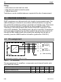
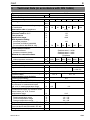
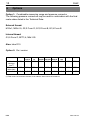
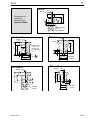
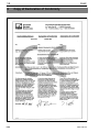
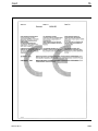
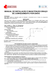
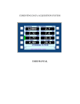
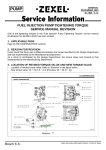
Operating manual
Absolute pressure
transducer
P8AP
A0514-30 en
3
P8AP
Contents
Page
Safety instructions . . . . . . . . . . . . . . . . . . . . . . . . . . . . . . . . . . . . . . . . . . . . . . . 4
1
List of components supplied . . . . . . . . . . . . . . . . . . . . . . . . . . . . . . . . . . . 7
2
Field of application . . . . . . . . . . . . . . . . . . . . . . . . . . . . . . . . . . . . . . . . . . . . 7
3
Mechanical construction . . . . . . . . . . . . . . . . . . . . . . . . . . . . . . . . . . . . . . . 7
4
Electrical connection . . . . . . . . . . . . . . . . . . . . . . . . . . . . . . . . . . . . . . . . . . 8
4.1 Pin assignment . . . . . . . . . . . . . . . . . . . . . . . . . . . . . . . . . . . . . . . . . . . . 8
5
Technical Data (in accordance with DIN 16086) . . . . . . . . . . . . . . . . . . 9
6
Options . . . . . . . . . . . . . . . . . . . . . . . . . . . . . . . . . . . . . . . . . . . . . . . . . . . . . 10
7
Dimensions . . . . . . . . . . . . . . . . . . . . . . . . . . . . . . . . . . . . . . . . . . . . . . . . . 13
8
Copy of Declaration of Conformity . . . . . . . . . . . . . . . . . . . . . . . . . . . . 14
A0514-30 en
HBM
4
P8AP
Safety instructions
Use in accordance with the regulations
The P8AP pressure transducer is to be used exclusively for pressure
measurement and directly related control tasks. Use for any additional
purpose shall be deemed to be not in accordance with the regulations.
To ensure safe operation the differential pressure gauge must be used only in
accordance with the information in the User Manual. It is also essential to
comply with the statutory and safety regulations relevant to the particular
application. This also applies to the use of accessories.
The differential pressure gauge is not a safety device even when used in accordance with the regulations. Perfectly safe operation of the differential pressure gauge requires proper transport, technically correct storage, installation
and assembly as well as careful operation and maintenance.
General dangers in non-observance of the safety instructions
The P8AP absolute pressure transducer corresponds to the state of the
art and is safe to operate. The differential pressure gauge may give rise to
further dangers if it is inappropriately installed and operated by untrained
personnel.
Any person instructed to carry out installation, commissioning, maintenance or
repair of the differential pressure gauge must have read and understood the
User Manual and in particular the technical safety instructions.
Residual dangers
The scope of supply and list of components supplied with the absolute pressure transducer cover only part of the scope of measurement technology. In
addition, equipment planners, installers and operators should plan, implement
and respond to the safety engineering considerations of measurement technology in such a way as to minimise remaining dangers. All existing regulations must be complied with. Reference must be made to remaining dangers
connected with measurement technology.
HBM
A0514-30 en
5
P8AP
In these mounting instructions remaining dangers are pointed out using the
following symbols:
DANGER
Symbol:
Meaning: Maximum danger level
Warns of an imminently dangerous situation in which failure to comply with
safety requirements will result in death or serious physical injury.
WARNING
Symbol:
Meaning: Potencially dangerous situation
Warns of a potentially dangerous situation in which failure to comply with
safety requirements can result in death or serious physical injury.
Symbol:
CAUTION
Meaning: Possibly dangerous situation
Warns of a potentially dangerous situation in which failure to comply with
safety requirements could result in damage to property or some form of
physical injury.
Symbol:
NOTE
Means that important information about the product or its handling is being
given.
Symbol:
Meaning: CE mark
The CE mark enables the manufacturer to guarantee that the product
complies with the requirements of the relevant EC directives (see Declaration
of Conformity at the end of this document).
A0514-30 en
HBM
6
P8AP
Conversions and modifications
The differential pressure gauge must not be modified from the design or
safety engineering point of view except with our express agreement. Any
modification precludes liability on our part for any damage resulting therefrom.
In particular, any repairs, soldering work on motherboards or replacement of
components is prohibited. Repairs may be carried out only by HBM.
Qualified personnel
This instrument is only to be installed and used by qualified personnel strictly
in accordance with the technical data and with the safety rules and regulations
below. It is also essential to comply with the statutory and safety regulations
relevant to the particular application. This also applies to the use of
accessories.
Qualified personnel means persons entrusted with the installation, assembly,
commissioning and operation of the product who possess the qualifications
appropriate to their function.
Conditions on site
Protect the transducer from damp and weather influences such as rain, snow,
etc.
Maintenance
The P8AP absloute pressure transducer is maintenance free.
Accident prevention
Even though the specified pressure in the destructive range is a multiple of
the final value of the measuring range, the relevant accident prevention regulations of the trade safety associations must be taken into consideration.
Thus, for example, a burst protector is to be provided on the transducer where
conditions cannot be perfectly defined.
Recalibration and repair
When you send the transducer for calibration or repair to HBM, please specify
the pressure medium used. Traces of the medium can always remain in the
measuring bore. We need this information to act adequately and, if required,
select the appropriate cleaning agent. If no medium has been specified, we
must possibly refuse to perform calibration or repair.
HBM
A0514-30 en
7
P8AP
1
List of components supplied
1 P8AP absolute pressure transducer
1 User Manual
2
Field of application
The P8AP series of absolute pressure transducers are suitable for measuring
static and dynamic pressures in fluids and gases. They are available for ranges 0...10, 0...20, 0...50, 0...100, 0...200 and 0...500 bar. Regardless of where
they are installed, the handy and compact transducers can be used even in
situations where space is at a premium.
3
Mechanical construction
P8AP pressure transducers are fitted with a connector tube (∅10 mm).
Where mechanical loading is high due to vibration or oscillation, and during
dynamic pressure measurement, we recommend retaining-ring glands on
safety grounds.
All commercially available clipping and retaining-ring glands can be used in
combination with the P8A during installation. The principle of clipping-ring
glands is illustrated in Fig.3.1 by the example of a progressive-ring gland
made by Ermeto Armaturen GmbH.
P8A tube
Sleeve-nut before tightening
Fig.3.1:
A0514-30 en
Sleeve-nut after tightening
Principle of the clipping-ring gland
HBM
8
P8AP
Fitting:
• Slide sleeve-nut and seal onto tube
• Plug tube into gland connection-piece
• Tighten sleeve-nut
Transducers can be installed wherever required at the site of measurement.
4
Electrical connection
P8AP transducers are delivered with a 5m length of unterminated cable. The
cable shielding is connected in accordance with the Greenline concept. By
this method the measuring system is enclosed in a Faraday cage. This means
that the measuring system is unaffected by electromagnetic interference.
Transducers with unterminated cable must be fitted with connectors conforming to EC standards. The shielding has to be put on smoothly. If transducers
are connected to amplifiers by any other method, the wiring loom must be fitted with an EMC-stable shield, and similarly the shielding must be put on
smoothly (see also HBM Greenline Information (publication G 36.35.0).
4.1 Pin assignment
-UB
bk
+UB bu
P
+UA wh
U
-UA
re
Excitation
voltage UB
Output
voltage UA
ye Cable shielding
Housing
Unterminated connector cable, 5m long
Fig.4.1:
Pin assignment
The pin assignment for amplifiers, compensators and channel transfer units
from HBM is as follows:
Cable termination at the transducer
Clamped or soldered connections
Amphenol connector pole
Tuchel connector pole
HBM
wh
bk
bu
re
ye
22
A
1
21
B
2
20
C
3
19
D
4
12
E
5
A0514-30 en
9
P8AP
5
Technical Data (in accordance with DIN 16086)
Type
Accuracy class
Mechanical input characteristics
Measurement span
Starting to measure
Fundamental resonance frequency
of membrane
Attenuation ratio of membrane
Operating range at 23°C
Overload cutoff at 23°C
Test pressure
Destructive range
With dynamic loading
permitted pressure
permitted oscillation bandwidth
(in accordance with DIN 50 100)
Material for parts in contact with the
measurement medium:
internal surfaces
pressure connector (tube)
Material for external surfaces
Dead volume with tube,
without pressure connector
Control volume
Output characteristics
Rated sensitivity
Input resistance
Output resistance
Rated range of the excitation voltage
(effective value)
Characteristic curve deviation
(Starting point setting)
Repeatability acc. to DIN 1319
Temperature coefficient of zero point,
by reference to measurement span,
per 10 K, in rated temperature range
Temperature coefficient of sensitivity
(measurement span), by reference to the
actual value, per 10 K, in rated
temperature range
Ambient conditions
Rated temperature range
Service temperature range
Storage temperature range
Impact resistance (acc. to DIN IEC 68)
Protection System
(in accordance with DIN 40050, IEC 68)
Weight (without cable) approx.
A0514-30 en
P8AP
0.3
bar
bar
(abs.)
10
kHz
1
%
%
%
%
12
20
50
100
200
500
60
0.01
0...150
175
175
>200
86
134
95
60
0
16
29
%
%
mm3
mm3
100
70
1110
(410)
mV/V
Ω
70
2 ± 2%
420 (+180/-120)
1020
(320)
0.3
370
(+130/-70)
330 (+90/-30)
0.5...5
%
%
%
95
Stainless steel 1.4542
Stainless steel 1.4301
Stainless steel 1.4301
Polythene
1100 1090 1060 1100
(400) (390) (360) (400)
2
1.5
0.5
Ω
V
85
0.5...12
0.3
±0.1
0.3
0.2
%
±0.3
°C
°C
°C
m/s2
-10...+70
-40...+80
-50...+85
800
IP67
g
40
HBM
10
6
P8AP
Options
Option 1: Combinable measuring range and pressure connector
The following pressure connectors may be used in combination with the final
scale values listed in the Technical Data:
External thread:
M10x1; M20x1.5; G1/2 Form D; G1/2 Form B; G1/4 Form B
Internal thread:
G1/4 Form Z; NPT1/4; M8x1.25
Also: tube D10
Option 2: Ex-i version
M10 x 1
G1/2
Form D
M20 x
1.5
G1/4
Form B
G1/2
Form B
G1/4
Form Z
M8 x
1.25
NPT1/4
Tube
Dead
volume2)
(mm3)
170
260
260
190
260
100
180
800
700
Final scale
value (bar)
500
500
1000
500
Material
1)
2)
16001) 16001)
1000
16001) 10001)
1.4542 1.4542 1.4542 1.4542 1.4542 1.4542 1.4542 1.4542 1.4571
Specifications in accordance with DIN 16 288
Dead volume of connector element, to be added to dead volume of transducer
HBM
A0514-30 en
11
P8AP
SW14
+0,2
Dimensions of
connector
elements with
external thread
∅3
2,5
°
∅5
∅8
M10
G1 Form D
SW27
13
19
M10x1
Packing surface
Flat / or
tapered gasket
M20x1.5
∅3
∅2
3
∅6
°
∅ 17.5
∅ 17.5
M20x1.5
G1/2 A
DIN 16288-D
SW27
∅3
∅5
∅ 10
IS0
228 G1/4
Packing
surface
5
8
5
3
13+0,3
32
20+0,3
SW27 ∅ 3
23
Packing
surface
G1 Form B
G1 Form B
A0514-30 en
32
20 +0,3
8
5
Packing surfaces for compact lenses
or tapered gasket
°
25 +0,3
32
SW27
∅5
∅ 17.5
ISO
228-G1/2
Packing
surface
HBM
12
P8AP
G1/4 Form Z
10
16,5
Dimensions of
connector
elements with
internal thread
∅ 5.5
ISO 228-G1/4
M8x1.25 internal
13
SW27
Packing surface
for flat gasket
NPT 1-18
SW27
∅16-0.
Packing surface
Flat gasket
SW14
∅ 11
NPT 1/4”-18
16,4
22,1
10
M8
11,5
8
1
Caulking
in thread
Tube Da\ 10
22,5
∅ 10
∅6
HBM
A0514-30 en
13
P8AP
5.2
6
Dimensions
10
7
Threaded connector in accordance with selection list
A0514-30 en
HBM
14
8
HBM
P8AP
Copy of Declaration of Conformity
A0514-30 en
P8AP
15
A0514-30 en
HBM
Modifications reserved.
All details describe our products in general form only.They are
not to be understood as express warranty and do not constitute
any liability whatsoever.
Hottinger Baldwin Messtechnik GmbH
A0514-30 en
Postfach 10 01 51, D-64201 Darmstadt
Im Tiefen See 45, D-64293 Darmstadt
Tel.: +49/61 51/ 8 03-0; Fax: +49/61 51/ 8039100
E-mail: [email protected] www.hbm.com