1
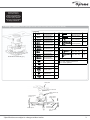
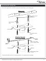
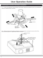
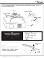
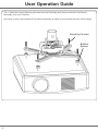
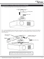
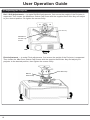
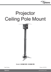
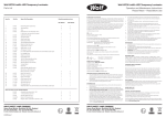
Projector
Flush Mount
ABtUS SIGAPORE PTE
LTDOCM818W / OCM818B
Model:
Patent Pending
Optoma Europe Limited
www.abtussingapore.com
Revision 04/01/2012
www.optoma.eu
User Operation Guide
IMPORTANT NOTES
●
Thank you for purchasing the Projector Flush Mount. This bracket is suitable for most
projectors up to a load of 15kg.
●
To ensure correct usage, please read this instruction manual thoroughly. Keep this manual for future
reference.
●
BRACKETS SHOULD BE MOUNTED ONLY BY A QUALIFIED INSTALLER.
●
User will be responsible for any injuries and damages that may arise from improper installation and
handing of Projector Flush Mounting Kit.
●
Ensure all mounting screws are appropriately positioned and properly tighten/ fastened.
●
Installers are to ensure customer’s safety during installtion.
●
We reserve the right to amend or undertake any necessary changes without prior notice.
●
Ensure the Ceiling can support the total weight of the Projector and the Projector Flush Mount.
●
All bolts and screws must be used at the designated points as per installation instructions to prevent
damage to the projector unit, or injury.
●
2
DO NOT install near an air conditioner or where there is excessive dust and smoke.
Please read these
instructions before
commencing installation
as faulty installation could
result in injury. Optoma
assumes no responsibility
for faulty installations.
Package Checklist (Each package should contain the parts listed and shown below)
Parts Bag
F
M4 x 15 Cross
Recessed Screw
M4 x 20 Cross
Recessed Screw
M4 x 25 Cross
Recessed Screw
M5 x 15 Cross
Recessed Screw
M5 x 20 Cross
Recessed Screw
M5 x 25 Cross
Recessed Screw
G
M6 x 15 Cross
Recessed Screw
4 pcs
3mm Allen Key
1 pc
H
M6 x 20 Cross
Recessed Screw
4 pcs
6mm Allen Key
1 pc
I
M6 x 25 Cross
Recessed Screw
4 pcs
J
1mm Washer
4 pcs
K
2mm Washer
4 pcs
L
4mm Washer
4 pcs
M
Bottom Spacer
4 pcs
N1
M5 x 10 Socket
Button Screw
4 pcs
N2
Square Nut
4 pcs
A
B
C
D
E
Flush Mount Assembly (x1)
4 pcs
a
4 pcs
b
M3 x 15 Cross
Recessed Screw
M3 x 20 Cross
Recessed Screw
c
M3 Flat Washer
4 pcs
d
Extension
Bracket (50mm)
4 pcs
4 pcs
4 pcs
4 pcs
4 pcs
4 pcs
4 pcs
Tools Included
Tools Required for mount assembly
1. 1x Star / Philips Screw Driver
2. 1x 13mm Spanner
Ceiling Plate
M4x6 Cross Recessed
Screw
M8x65 Socket Cap
Screw
Cross Recessed
Screw A—I
Extension Bracket
(100mm)
Bottom Spacer
M5x10 Socket
Button Screw
Square
Nut
Extension
Bracket (50mm)
1mm, 2mm, 4mm
Washers
*Specifications are subject to changes without notice.
3
User Operation Guide
(A) Removing the Ceiling Plate from the Flush Mount Assembly:
1. Loosen the M4x6 (x2) Cross Recessed Screw with a screw driver
2. Remove the M8x55 Socket Cap Screw and Nylock Nut from the Flush Mount Assembly as shown.
3. Removing the Ceiling Plate from the Flush Mount Assembly.
M8x55 Socket Cap Screw
Ceiling Plate
M8 Nylock Nut
M4x6 Cross
Recessed
Screw
Screw driver
6mm Allen Key
4
(B) Installing the Ceiling Plate:
Choose the appropriate installation procedure depending on your ceiling type.
Masonry
8mm (5/16”)
Holes
Nylon Anchor
Plug
*Washer
Ceiling Plate
*14 Gauge Coach
Screw
Plaster Board
Plaster
Board
3mm (1/8”) Holes
drill on Timber Beam
Timber
Beam
Ceiling Plate
*Washer
*14 Gauge Coach
Screw
* Plug and Screws are only for recommendation, not supplied within package
*Specifications are subject to changes without notice.
5
User Operation Guide
(C) Attaching the Flush Mount Assembly to the projector:
C.1— Loosen the M5x10mm Socket Button Cap Screws using the 3mm Allen key until you can slide the
extension brackets freely, as shown.
Extension Bracket
100mm
3mm Allen key
M5x10mm
Socket Button
Cap Screw
C.2— Place projector’s Flush Mount Assembly over the projector and align the centre of the Flush
Mount with the projector’s approximate Centre of Gravity.
Centre of Flush
Mount
This surface to be approximate parallel to
the projector front
Centre of Gravity
6
C.3— Place the Bottom Spacers in between the Extension Brackets and the Projector, and align the
mounting holes as shown below.
Extension Bracket
Bottom Spacer
Bottom Spacer
Mounting hole
NOTE
If the mounting holes on your projector
are recessed, you may need to use
the additional spacers supplied in the
parts bag. Please select the appropriate
spacers according to the design of
your projector.
Note 2:
If you cannot align the 100mm Extension
Bracket to the mounting hole on your
projector, you may need to use the
additional 50mm Extension Brackets
shown in the diagram on the right.
M5x10mm
Screw
Extension Bracket
Square Nut
Bottom Spacer
*Specifications are subject to changes without notice.
7
User Operation Guide
C.4— Select the correct Mounting Screws from the Parts bag and firmly screw the Flush Mount
Assembly onto your Projector.
Once this is done, the Projector Flush Mount Assembly is ready to be mounted onto the Ceiling Plate.
Mounting Screws
Bottom
Spacer
8
(D) Attaching the Flush Mount Assembly to the Ceiling Plate
D.1— Connect the Short Pole to the Ceiling Plate as shown be-
Ceiling Plate
Short Pole
D.2— Insert the M8x55 Socket Cap Screw into the slot on the Ceiling Plate to lock the Flush Mount
Assembly with the M8 Nylock Nut. Tighten the M4x5 Cross Recessed Screws to balance the Flush
Mount Assembly.
M8 Nylock Nut
and Washer
**M8X55 Socket Cap
Screw and Washer
Screw
Driver
M4X6 Cross
Recessed
Screw
6mm Allen Key
Tip: When the Projector required servicing, remove the
Projector via the easy disconnection point** to save time.
*Specifications are subject to changes without notice.
9
User Operation Guide
(E) Adjusting the Projector
Roll / Shift Adjustments — to make Roll/Shift adjustments, first ensure the weight of the Projector is
supported. Then loosen the M8x65mm Socket Cap Screw with the supplied 6mm Allen Key and adjust
to your desired position. Re tighten the screws firmly.
6mm Allen Key
M8X65mm
Socket Cap
Screw
Roll
Roll
Shift
Pitch Adjustment — to make Pitch adjustments, first ensure the weight of the Projector is supported.
Then loosen the M8x15mm Socket Cap Screws with the supplied 6mm Allen Key and adjust your
projector to the desired position, then tighten the screws firmly.
M8x15
Socket Cap
Pitch
10
6mm Allen Key
Pitch
*Specifications are subject to changes without notice.
11
Due to continuing product development, the manufacturer reserves the right to alter specifications without notice. Published: 04.01.2012