1
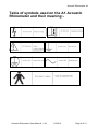
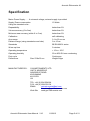
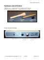
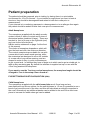
Acoustic Rhinometer A1 Acoustic Rhinometer A1 User Manual V10 Acoustic Rhinometer User Manual V10 11/09/12 Page 1 of 21 Acoustic Rhinometer A1 A1 Acoustic Rhinometer Safety Information WARNINGS The system must not be used in the presence of flammable gases or in an environment, which is susceptible to explosions. (Beware of oxygen, dust and anaesthetic gases!) If your PC or printer does not have a power supply approved for a patient environment, then an isolation transformer, which is in compliance with BS EN 60601 should be used to power the PC, printer and the A1 Acoustic Rhinometer. You must use the isolation transformer to ensure that the A1 Acoustic Rhinometer is in compliance with BS EN 60601. Parts marked for single use should not be re-used as no method of sterilisation can be guaranteed, disinfection materials may not be effective and may leave a residue, which could be harmful. As this is a mains powered, PC connected product, it is advisable not to touch the patient while using the equipment. CAUTIONS The nosepieces are made of a material, which may cause an irritation reaction in some patients. Use of the nosepiece should be discontinued in patients who exhibit such a reaction. Nosepieces are a single use item. Single use items should not be reused as they could carry infections between subjects. Federal (USA) law restricts this device to sale by or on the order of a physician. The use of an A1 Acoustic Rhinometer near to sources of electromagnetic radiation, such as mobile phones, radio transmitters, x-ray equipment etc, may prevent it from functioning correctly. The A1 Acoustic Rhinometer is a medical instrument, which has an electrical classification of Class 1 Type B and a Medical Device Directive classification of 2a. A Class 1 Type B device categorisation is used to describe an instrument which:a) Does not rely on basic insulation only to provide protection against electrical shock but is constructed in such a way that accessible metal parts cannot become live in the event of failure of the basic insulation and b) Applied parts offer protection to the subject against electrical shock and in the event of a single fault condition arising, leakage current will be limited to less than 0.5 mA. Acoustic Rhinometer User Manual V10 11/09/12 Page 2 of 21 Acoustic Rhinometer A1 Any incident, which results in actual or potential injury or death to a subject while using A1 should be immediately communicated to GM Instruments at the address below. A1 should only be connected to other devices such as computers and printers, which comply with EN 60950. Unless computers and printers built to EN 60950 are used, patient safety might be compromised. Non medical equipment such as computers and printers should be kept out of reach of subjects being tested as such equipment does not comply with medical safety standards. If the PC is allowed to go in to sleep mode, the USB interface is powered down. When brought out of sleep mode, the PC does not re initialise the USB interface, and therefore it is effectively not present. A solution is to remove the USB connection at the PC or instrument side then re connect. That may be sufficient, but if not, save any results, then close down the instrument software and restart it Servicing can only be carried out by GMI approved and authorised personnel. No modifications are allowed. Storage The A1 Acoustic rhinometer and its accessories should be stored within the following temperature and humidity range:Temperature Humidity -40C to + 60C 20 to 80% RH non condensing Accuracy Information Standardisation Document. Customers are referred to the under noted International Standardisation Committee publication which contains recommendations on the use of Acoustic Rhinometers. Acoustic Rhinometry: Recommendations for technical specifications and standard operating procedures. Rhinology supplement number 10, December 2000 Ole Hilberg and Ole Pedersen Acoustic Rhinometer User Manual V10 11/09/12 Page 3 of 21 Acoustic Rhinometer A1 Table of symbols used on the A1 Acoustic Rhinometer and their meaning:- Acoustic Rhinometer User Manual V10 11/09/12 Page 4 of 21 Acoustic Rhinometer A1 Specification Mains Power Supply ….. A universal voltage, external supply is provided Supply Power consumption 10 Watts Using the standard nose:Repeatability better than 2% Volume accuracy (0 to 5cm) better than 2% Minimum area accuracy (within 0 to 5 cm) better than 5% Calibration self calibrating Area range 0.1 to 20 cm.cm Distance range (using standard sound tube) 0 to 15 cm Standards BS EN 60601 series Warm up time 5 minutes Operating temperature + 15 to + 35C Operating humidity 20 to 80% RH non condensing Duty cycle Continuous Dimensions Size 27x8x30 cm Weight 2Kgm MANUFACTURED BY: G M INSTRUMENTS LTD UNIT 6 ASHGROVE ASHGROVE ROAD KILWINNING KA13 6PU UK TEL: +44 (0)1294 554664 FAX: +44 (0)1294 551154 EMAIL [email protected] [email protected] Web Site www.gm-instruments.com Acoustic Rhinometer User Manual V10 11/09/12 Page 5 of 21 Acoustic Rhinometer A1 CONTENTS A1 Acoustic Rhinometer Safety Information Page 2 Symbols Used Page 4 Specification Page 5 Introduction General Introduction To The Technique Page 7 Installation Installing The Hardware Page 8 Installing The Software Page 8 Hardware Identifier Page 9 To Make And Record Measurements Calibration Page 10 Patient Preparation Page 11 Nosepiece Options Page 11 Making Measurements Page 12 Factors which affect accuracy Page 13 Environmental Factors Page 14 Maintenance Overview Page 15 Spare Parts And Accessories Page 15 A1 Troubleshooting Page 16 Electrical Information Page 18 Instrument Cleaning And Decontamination Page 19 How To Sterilise Patient Applied Parts Page 20 Acoustic Rhinometer User Manual V10 11/09/12 Page 6 of 21 Acoustic Rhinometer A1 INTRODUCTION Hardware and software has been provided with the A1 Acoustic Rhinometer to allow the determination of Nasal Area-Distance plots by Acoustic Reflections. The method is based on the following principle : A sound pulse propagates in a tube and enters the nasal cavity through a nosepiece. Here it is reflected by local changes in cross-sectional area. The incident, and reflected, signals are measured by a microphone in the sound tube. From these measurements it is possible to calculate the cross-sectional area as a function of the distance into the cavity by use of algorithms developed by Ware and Aki (1969). By integration of this curve the volume of the nasal cavity is calculated. The method has been developed for use in the tracheo-bronchial system by Jackson et al.(1977). and for use in the nose by Hilberg et al.(1989). For further information the reader should consult these publications :1. JACKSON, A.C., J.P.BUTLER, E.J.MILLET, F.G.HOPPIN JR, AND S.V.DAWSON. Airway geometry by analysis of acoustic pulse response measurements. J.Appl.Physiol. 43(3):523-536,1977. 2. WARE, J.A., AND K. AKI. Continuous and discrete inverse scattering problems in a stratified elastic medium. I. Plane waves at normal incidence. J.Acoust. Soc.Am.45:911- 921,1969. 3. HILBERG,O., A.C.JACKSON, D.L.SWIFT, AND O.F.PEDERSEN. Acoustic rhinometry, evaluation of nasal cavity geometry by acoustic reflection. J.Appl.Physiol.66:295303,1989. Acoustic Rhinometer User Manual V10 11/09/12 Page 7 of 21 Acoustic Rhinometer A1 INSTALLATION Installing the hardware The A1 Acoustic Rhinometer can be made to work on any PC, which can run Windows 2000, XP, Vista or Windows 7 and which has a free USB socket. NB units which comply with EN60950 should be used. Installing the A1 unit Connections between the A1 box, it’s sound tube, it’s power module and the PC is by means of polarised connectors which can only be inserted in the correct place and the correct way round. Connect the sound tube and the power module prior to powering up the A1, but do not connect the USB cable until the A1 software and A/D board driver is installed. . Installing the A1 software Installation of the A1 software is described fully in the accompanying manual titled “A1 Acoustic Rhinometer Software Manual” Acoustic Rhinometer User Manual V10 11/09/12 Page 8 of 21 Acoustic Rhinometer A1 Hardware Identification Calibration plug ---- supplied with the A1 Compact and A1 Executive Artificial nose and Straight Tube ---- supplied with the A1 Executive A1 rear view and connections USB socket Acoustic Rhinometer User Manual V10 Sound Tube socket 11/09/12 Power module socket Page 9 of 21 Acoustic Rhinometer A1 TO MAKE AND RECORD MEASUREMENTS Having become familiar with the hardware and software you are now ready to record measurements. Calibration Having set the various options to the way you want, the next thing to do is calibration. To do a calibration, switch on the A1, put the calibration plug in the sound tube, click on the top bar acquisition icon and then on the Calibrate button as shown below. A message Calibration OK will show when completed. A1 sound tube with calibration plug fitted, ready for calibration. The system is now ready for use. Acoustic Rhinometer User Manual V10 11/09/12 Page 10 of 21 Acoustic Rhinometer A1 Patient preparation The patient should be prepared, prior to testing, by having them in a quiet stable environment for 15 to 20 minutes. If your interest is surgical and you want to look at structure, they should be decongested and asked to blow their nose prior to measurement. If your interest is in monitoring response to a decongestant or to an allergen then again the patient should be asked to blow their nose prior to measurement. Adult Nosepieces The nosepieces supplied with the adult acoustic system include 3 sizes of conical and 2 sizes of anatomical probes (medium & large). These are handed i.e. one is for use on the right side (red) and one for the left side (blue). NB the caution statement on page 2 at the front of this manual. The choice of nosepiece depends on which will give the best seal with, the minimum distortion. The conical nosepieces are suitable for use with a nose which has a small round opening, while the anatomical are designed to sit on the outside of a nose with a long narrow opening, and are shaped to make it easy, in most circumstances, to get a good seal. In addition they have a flange onto which can be put a soluble gel, to take up any remaining gap. By default the software is supplied set up for use with the 4.5cm long anatomical nosepieces. If you want to use the 7cm long conical nosepieces, the nosepiece length should be changed to 7cm in the setup screen found at:FILE/SETTINGS/ACOUSTIC/ACQUISITION (Adv) Child Nosepieces The nosepieces supplied with the child sound tube are 4.5cms long and are manufactured from silicone rubber. As the wall thickness is 1.5 mm it is possible to run a bead of gel round the end of the tube, and this will help obtain an airtight connection to the nose. Alternatively an additional washer can be added to the end of the child nose piece to increase the width where gel can be added. Acoustic Rhinometer User Manual V10 11/09/12 Page 11 of 21 Acoustic Rhinometer A1 Making measurements 1) Have the patient sit back in a chair (some workers advocate use of an adjustable forehead and chin rest), select and fit a nosepiece, and apply the sound tube (perhaps suitably prepared with gel) to the side to be measured. The sound tube can be held by the patient, or by the clinician but we believe this is best left to the patient, with one hand holding the sound tube near the bottom and one near the top. 2) When suitably positioned ask the patient to close their mouth and gently breath in and out through their nose to check for leakage between the sound tube and nose. 3) If ok ask them to open their mouth, and return to mouth breathing. When ready to make the measurement, ask them to breath in and then hold their breath. Click on the red acquire button to sample the data. This process can be repeated until at least 3 consecutive results show little variation. If the patient can cooperate the measurements may be made in rapid succession (with 600mS or so between samples) during a single breath hold manoeuvre. NB a footswitch is available as an alternative to clicking on the red acquire button. 4) If the results are satisfactory select the other side (L or R) and repeat the process. 5) The test results are automatically added to the patient results file. 6) Click on print, to print out the currently highlighted curves, or alternatively click on output to select the curves from the displayed list for printout. 7) The results can be saved by clicking on save, confirming the file name to save to, and then clicking on ok. Switching Off The program can be closed by clicking on FILE and then selecting EXIT from the drop down menu. NB If you allow the PC to go to sleep, Acoustic Rhinometer User Manual V10 11/09/12 Page 12 of 21 Acoustic Rhinometer A1 Factors which affect accuracy Measurement accuracy and repeatability will depend on the following:Calibration:- Do and accept (save) a calibration at least twice a day. Temperature:- Use equipment in controlled conditions between 20 & 23°C. External noise:- Use equipment in conditions where the background noise is below 65 dB. Angle of probe (relative to the head):- Aim for floor of nose. Rigidity of probe Don't move. Effect of probe on the nose:- Avoid distortion. Patient cooperation:- Hold breath during measures. Nosepiece/nose seal:- Use gel and careful positioning to ensure seal. Check for leaks/Distortion:- Repeat test at least twice if not 3 times and check for variation i.e. apply/remove probe 2 or 3 times, testing each time and compare results. The Acoustic Standardisation Committee have now reported on the measurement and this is referred to on page 3 of this manual. Acoustic Rhinometer User Manual V10 11/09/12 Page 13 of 21 Acoustic Rhinometer A1 Environmental factors Temperature effect An increase in the temperature of the gas through which the sound pulse travels lowers its density and therefore the rate at which it travels through the gas. The overall effect is in the range of 3% / 20 C. Distance is therefore slightly overestimated if there is an increase in temperature. Altitude effect The effect of altitude is significant on the density of a gas and therefore on the speed of sound at an altitude of 1000m, distance is overestimated by 7%. Acoustic Rhinometer User Manual V10 11/09/12 Page 14 of 21 Acoustic Rhinometer A1 MAINTENANCE Overview The acoustic rhinometer should be calibrated each day using the inbuilt facility. In addition to this the cables should be inspected regularly for signs of damage, in particular in the region of the sound tube and link to the PC. The nosepieces supplied are for single use only. Care should be taken in use to prevent the passage of nasal secretions down the nosepiece and into the sound tube. Should this occur, the sound tube should be removed from the sound box, cleaned by one of the methods described below and then thoroughly dried prior to fitting back on the sound box. NB take care not to over tighten the fixing screws when re fitting the tube. Spare Parts and Accessories. Nosepieces:A1/PR M Medium anatomically conformed nosepiece A1/PR L Large anatomically conformed nosepiece A1/PR 8 Small conical nosepiece A1/PR 10 Medium conical nosepiece A1/PR12 Large conical nosepiece Misc. :A1/PLUG Replacement calibration plug A1/MIC Replacement microphone and inner sound tube A1/CABLE USB Cable Acoustic Rhinometer User Manual V10 11/09/12 Page 15 of 21 Acoustic Rhinometer A1 A1 TROUBLESHOOTING. If the PC is allowed to go in to sleep mode, the USB interface is powered down. When brought out of sleep mode, the PC does not re initialise the USB interface, and therefore it is effectively not present. A solution is to remove the USB connection at the PC or instrument side then re connect. That may be sufficient, but if not, save any results, then close down the instrument software and restart it It is important that the software is loaded in the sequence suggested in the installation section of the A1 Acoustic user software guide. There are a number of ways of checking that this has been done correctlyNavigate to the MCC (Measurement Computing Company) folder, using My Computer and double click on the program Inscal32.exe. The opening dialog will show which boards are installed. The board you installed should be numbered 0. Right click on the board, and check that it is configured to 4 channel differential. Click ok once confirmed. Select TEST from the top bar and ANALOG from the drop down menu then CHO, signal source EXTERNAL and A/D range + 1.25V. The line you see should lie on zero volts and should respond to talking into the open end of the sound tube – if this is ok then the microphone and connections between A1, the A/D card and the PC are ok. Acoustic Rhinometer User Manual V10 11/09/12 Page 16 of 21 Acoustic Rhinometer A1 In the A1 folder you will find a program called A1TEST.EXE. Start it, select Gain = BIP1PT25 volts, Digital Port =A1, Sample Rate = 46000. Click on SAMPLE. You should see a pulse train on the screen. If you point the mouse cursor under the trace, it will tell you the amplitude of the trace at each point. The baseline should be between 1950 and 2050. The value is only updated when you click on SAMPLE. The picture below shows a typical display when the calibration plug is fitted to the sound tube and sample is selected. The peak pulse size can also be measured in this way but is also listed numerically on the table on the left hand side. It should peak at a level greater than that set within the A1 program for TRIGGER, and is normally set to greater than 2600 but smaller than 4000. If smaller than 2600 the level can can be increased by using the GAIN control VR2 on the A1 circuit board. If the calibration plug is removed, the trace will change as shown below and you will be able to hear the click when SAMPLE is selected. Acoustic Rhinometer User Manual V10 11/09/12 Page 17 of 21 Acoustic Rhinometer A1 The traces above show the microphone signal output plotted against time. The first large peak shows the response when the click sound reaches the microphone on it’s way up the tube. On the trace at the top of this page, the second peak shows the reflected signal from the calibration plug returning back down the tube and reaching the microphone again. Each pair, which follows shows the event repeating, as the sound travels up and down the closed tube. Selection of what constitutes incident and reflected waves is controlled by settings within the A1 program for incident wave window, reflected wave start point and reflected wavelength. These are set for a particular sound tube and should not be altered. Explanation of how the program Instacal works. Each time Instacal is opened, it looks to see what Measurement Computing Company interfaces it can find. The first one it finds it allocates to board 0 and the next to board 1 etc. It records the board type and serial number and automatically edits an INI file to include this information. If you change one acoustic system for another, it will have the same board type, but it will have a different serial number, which means that the USB will not be recognised and the driver will not be loaded. If you run Instacal again, it looks for Measurement Computing Company interfaces. It realises that the one already recorded is no longer present (by comparing serial numbers) and offers to remove it. When you answer yes, Instacal offers to record the new USB interface and when you say yes it edits the INI file to include the new board type and serial number. If board 0 is free, it automatically allocates it to board 0. It is for these reasons that you can't just unplug one A1 instrument and replace it with another. You must run Instacal to let it recognise that the first one is no longer present, delete it and replace it with the new one. If you have 2 A1 connected, both can be registered by Instacal ---- one as board 0 and one as board 1. Provided you go into the software of one of them (TOOLS/SETTINGS/DEVICE) and change it to board 1 then you can easily switch between each system without having to run Instacal. If one or both are linked TO A1/NR6 (Naris) systems the DEVICE tab for the rhinomanometer section would need to be changed to board 1 as well as in the acoustic section. One weakness we have found in the Instacal arrangement is that if the PC goes into sleep mode, the PC closes down USB connections --- turns off the power etc --- and when brought out of sleep, it doesn't load the driver back in again. You either have to unplug and then plug back in again the USB cable, or close down and then reboot the PC. Electrical Information. Servicing of the A1 acoustic rhinometer can only be undertaken by factory trained personnel or engineers familiar with the standard EN 60601. Circuit diagrams will be made available to competent persons on request. Acoustic Rhinometer User Manual V10 11/09/12 Page 18 of 21 Acoustic Rhinometer A1 Instrument cleaning / decontamination procedure Enclosure Should the enclosure require cleaning for any reason, unplug it from the PC and wipe it with a damp cloth, or a cloth soaked in a mild alcohol based solution or cleaning wipes. Do not allow liquid to run into the enclosure. Sound Tube In normal use, using the disposable nosepieces supplied, no routine cleaning is believed necessary. If in the course of use material should run past the nosepiece and into the sound tube this can be cleaned as follows:a) Switch off power to the instrument, unplug it’s supply and disconnect the USB link to the computer. b) Loosen the white round-headed screws, which secure the outer tube to the base. Loosen the white insert screw, which helps secure the outer tube to the inner, near the nosepiece end of the sound tube. Carefully slide the outer tube towards the nosepiece end of the sound tube, to uncover the microphone connector, then prise the microphone cable connectors apart. c) Loosen the inner sound tube securing white insert screw from the sound generator box and withdraw the tube. The tube can now be cleaned with an antiseptic wipe (push the wipe down the sound tube with a suitably long thin object) and if desired, gas sterilised. Do not allow liquids to run into the tube as the microphone could be damaged. e) Assembly is the opposite of the process above. Particular attention should be paid to ensuring 1) the sound tube locates fully in the holder at the bottom of the sound generator box and is held in this position while securing it carefully with the insert screw. 2) The microphone is carefully reconnected to the system by connecting the plug and socket again, but without pulling at the cable while doing so. 3) The outer tube is replaced after the microphone has been reconnected and securing screws replaced. Acoustic Rhinometer User Manual V10 11/09/12 Page 19 of 21 Acoustic Rhinometer A1 How to sterilise reusable patient applied parts Never reuse or re-sterilize any patient applied part whose original package was labelled with FOR ONE TIME USE, SINGLE USE, DISPOSE AFTER USE or equivalent wording. When in doubt about whether a patient applied part can be re-sterilised, always consider it for one time use. The following sterilisation procedure is intended for removable, reusable patient applied parts manufactured by GMI. For a product that is sold by GMI but not manufactured by GMI, refer to the sterilisation procedures in that product's operating manual where appropriate. DO NOT STERILISE THE INSTRUMENT. To sterilise patient applied parts follow these directions: 1) Place each part in a suitable vented sterilisation pouch (e.g. Tyvak side or port). Include a sterility indicator designed for use with Ethylene Oxide and heat seal the package with a device specifically designed for this purpose. 2) Place the sealed packages in a sterilisation chamber designed for 100% ethylene oxide gas. After loading the packages according to the sterilisation chamber manufacturer's directions, close and secure the chamber door. 3) Evacuate the sterilisation chamber to a pressure of 0.01 atmospheres (7.6 mm Hg). 4) Fill the sterilisation chamber with 100% ethylene oxide gas until the chamber pressure reaches 0.2 atmospheres (152 mm Hg). 5) Increase the sterilisation chamber temperature to 48 C. 6) Maintain the sterilisation chamber temperature at 48 C for 210 minutes (3.5 hours). 7) Reduce the sterilisation chamber temperature to room temperature. Purge ethylene oxide from the sterilisation chamber according to manufacturer's directions and local environmental regulations. 8) After sterilisation place the sealed packages in a quarantined, ventilated area away from human contact for at least 2 days to allow any residual ethylene oxide gas to disperse. Follow local environmental regulations selecting the area and posting necessary cautionary statements. 9) Examine each sealed package's sterility indicator. Discard or re-sterilize any part if its sterility indicator is negative or the package is broken or opened. Store the sterilised packages in a cool, dry place. Sterilization chamber conditions may be affected by age, lack of periodic re-calibration, metering errors or other problems. The effectiveness of the sterilisation procedure with your specific equipment should be validated by an independent, accredited testing laboratory to certify sterility and package integrity after sterilisation. Check with a local accredited laboratory for further guidance. Never make the assumption that re-sterilised Acoustic Rhinometer User Manual V10 11/09/12 Page 20 of 21 Acoustic Rhinometer A1 patient applied parts are sterile until sterility certification has been established. GMI assumes no responsibility that this sterilisation procedure for patient applied parts will be effective with your specific sterilisation equipment. Independent sterility certification by an accredited testing laboratory is the only validation method that can establish this level of confidence. Acoustic Rhinometer User Manual V10 11/09/12 Page 21 of 21