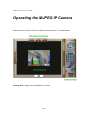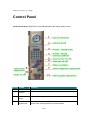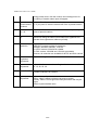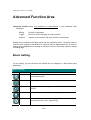
1
MJPEG IP Camera
User Manual Version 2.1.7
MJCAS-310PTD
MJPEG IP Camera User’s Guide
© 2004~2005.
Owner's Record
The model and serial numbers are located at the bottom. Record these numbers in the spaces provided
below. Refer to these numbers whenever you call upon your dealer regarding this product.
Model No. ______________ Serial No. ____________________
To prevent fire or shock hazard, do not expose the unit to rain or
moisture.
For AC Adaptor to avoid electrical shock, do not open the cabinet. Refer
servicing to qualified personnel only.
For customers in the U.S.A.
This equipment has been tested and found to comply with the limits for a digital device, pursuant to
Part 15 of the FCC Rules. These limits are designed to provide reasonable protection against harmful
interference in a residential installation. This equipment generates, uses, and can radiate radio
frequency energy and, if not installed and used in accordance with the instructions, may cause harmful
interference to radio communications. However, there is no guarantee that interference will not occur
in a particular installation. If this equipment does cause harmful interference to radio or television
reception, which can be determined by turning the equipment off and on, the user is encouraged to try
to correct the interference by one or more of the following measures:
– Reorient or relocate the receiving antenna.
– Increase the separation between the equipment and receiver.
– Connect the equipment into an outlet on a circuit different from that to which the receiver is
connected.
– Consult the dealer or an experienced radio/TV technician for help.
You are cautioned that any changes or modifications not expressly approved in this manual could void
your authority to operate this equipment.
The shielded interface cable recommended in this manual must be used with this equipment in
order to comply with the limits for a digital device pursuant to Part 15 of FCC Rules.
Declaration of Conformity
2/94
MJPEG IP Camera User’s Guide
This device complies with part 15 of the FCC Rules. Operation is subject to the following two
conditions:
(1) this device may not cause harmful interference, and
(2) this device must accept any interference received, including interference that may cause
undesired operation.
NOTICE TO USERS
© 2004~2005. All rights reserved. This manual or the software described herein, in whole or in part,
may not be reproduced, translated or reduced to any machine readable form without prior written
approval.
WE PROVIDES NO WARRANTY WITH REGARD TO THIS MANUAL, THE SOFTWARE OR
OTHER INFORMATION CONTAINED HEREIN AND HEREBY EXPRESSLY DISCLAIMS
ANY IMPLIED WARRANTIES OF MERCHANTABILITY OR FITNESS FOR ANY
PARTICULAR PURPOSE WITH REGARD TO THIS MANUAL, THE SOFTWARE OR SUCH
OTHER INFORMATION. IN NO EVENT SHALL WE BE LIABLE FOR ANY INCIDENTAL,
CONSEQUENTIAL OR SPECIAL DAMAGES, WHETHER BASED ON TORT, CONTRACT, OR
OTHERWISE, ARISING OUT OF OR IN CONNECTION WITH THIS MANUAL, THE
SOFTWARE OR OTHER INFORMATION CONTAINED HEREIN OR THE USE THEREOF.
We reserves the right to make any modification to this manual or the information contained herein at
any time without notice. The software described herein may also be governed by the terms of a
separate user license agreement.
3/94
MJPEG IP Camera User’s Guide
Table of Contents
Overview ............................................................................................................................. 6
Package Contents................................................................................................................ 8
Connections....................................................................................................................... 11
Hardware Installation....................................................................................................... 13
Logging in to Homepage................................................................................................... 15
Before Operation....................................................................................................... 15
Access the MJPEG IP Camera from the Internet Explorer for the first time............ 19
Logging in as an ordinary User................................................................................. 21
Logging in as an Administrator................................................................................. 21
Operating the MJPEG IP Camera.................................................................................... 22
Control Panel ............................................................................................................ 23
Advanced Function Area........................................................................................... 25
Basic Setting ..................................................................................................... 25
System .......................................................................................... 26
Camera.......................................................................................... 28
Network ........................................................................................ 31
User............................................................................................... 37
IP Filter ......................................................................................... 38
FTP Client..................................................................................... 41
SMTP............................................................................................ 43
Image Memory ............................................................................. 45
Alarm 1 ......................................................................................... 47
Alarm 2 ......................................................................................... 48
4/94
MJPEG IP Camera User’s Guide
Schedule ....................................................................................... 49
Motion Detection.......................................................................... 50
Time Setting ................................................................................. 51
Popup ............................................................................................ 53
Firmware upgrade:........................................................................ 54
Factory Default............................................................................. 57
Reboot........................................................................................... 58
Trigger............................................................................................................... 59
Capture.............................................................................................................. 60
RightMouseButton of ActiveX Control.............................................................................. 61
View Menu................................................................................................................ 62
“Image Recording…-> Save as JPEG” .................................................................... 68
“Save Current Picture As …” ................................................................................... 74
Appendix A: Restore Factory Default Settings ................................................................. 76
Appendix B: Alarm I/O Connector ................................................................................... 77
Appendix C: Troubleshooting & Frequently Asked Questions ......................................... 79
Appendix C: Troubleshooting & Frequently Asked Questions ......................................... 79
Appendix D: PING IP Address ......................................................................................... 84
Appendix E: Bandwidth Estimation .................................................................................. 85
Appendix F: Specifications ............................................................................................... 86
Appendix G: Time Zone Table........................................................................................... 88
Appendix H: DDNS Application ....................................................................................... 90
5/94
MJPEG IP Camera User’s Guide
Overview
This user’s guide explains how to operate the MJPEG IP Camera from a computer.
Basically, the user’s guide is written to be read on the computer display. However, users
might consider printing it out to access easily and read it before you operate the MJPEG
IP Camera.
Introduction
This MJPEG IP Camera is an inexpensive fully scalable surveillance technology.
Because the MJPEG IP Cameras can be plugged in to your existing computer network
infrastructure, you will potentially save thousands of dollars on unnecessary cabling.
The MJPEG IP Camera is accessible via the LAN or Internet connection. Connect your
MJPEG IP Camera directly to a computer network or DSL modem, and with a standard
Web browser you get instant, on demand video streams. Within minutes you can set up
the MJPEG IP Camera to capture a video sequence to a PC. Live video image can be
uploaded to a website for the world to see or made available only to select users on the
network.
Features:
z
High quality 1/3” CCD sensor
z
Composite video output
z
Motorized and wide-range pan and tilt operation
z
16 Preset Points
z
JPEG video compression
z
Built-in internal microphone
z
Remote-Control via Internet Explorer
z
Support statistic and dynamic IP address
z
DDNS and PPPoE
z
CF memory card interface (for CF card enabled version only)
z
Multi-channel control software for surveillance application
z
On-line firmware upgrade
6/94
MJPEG IP Camera User’s Guide
Application:
z
Remote monitoring
z
Surveillance
Minimum System Requirement
z
Microsoft Internet Explorer 5.0 or later
z
VGA Monitor resolution 1024 x 768
z
Pentium 4 1.3GHz or above
z
Memory Size: 256MB or above
z
Windows ME, 2000, XP, or 2003
7/94
MJPEG IP Camera User’s Guide
Package Contents
User can find the following items in the package:
1.
2.
3.
4.
5.
6.
7.
8.
PT MJPEG IP Camera x 1
Power adapter x 1
Power cord x 1
Decoration ring x 1
Screw x 4
Terminator for Alarm I/O x 1
Installation software and manual CD x 1
Quick Start Guide x 1
Item
Descriptions
1. This unit is the main element of
the system.
2. Switching Power Adapter
dedicates 12V DC electric power
output to MJPEG IP Camera.
8/94
MJPEG IP Camera User’s Guide
3. Power Cord provides connection
between AC Power Adapter and
Power Outlet for electricity.
4. Decorate the mounting parts.
Provide four screw holes to fix
MJPEG IP Camera.
5. Screws are used to fix MJPEG
IP Camera.
6. Alarm I/O connector is used to
provide an easy fixing interface for
the wire connection from alarm
devices and sensor devices to
MJPEG IP Camera.
7. User’s Manual provides
important information and
instructions for operating the
MJPEG IP Camera.
9/94
MJPEG IP Camera User’s Guide
8. Quick Start Guide provides
important information and
instructions for installing this device.
If any of the above items are missing, please contact your dealer immediately.
Note: Using a power supply with a different voltage than the one included with the
MJPEG IP Camera will cause damage and void the warranty for this product.
10/94
MJPEG IP Camera User’s Guide
Connections
DC Power and Video Output Cable
The DC power input and video output cable are located on the MJPEG IP Camera’s
back panel. The input power is 12VDC. Note that supply the power to the MJPEG IP
Camera with standard power adapter included in package. Otherwise, the improper
power adapter may damage the unit and result in danger.
The MJPEG IP Camera also provides composite video output. User can use BNC video
cable to connect the MJPEG IP Camera with a TV monitor or VCR.
LAN Socket
Beside the DC power and video output cable, the LAN socket is an RJ-45 connector for
connections to 10Base-T Ethernet or 100Base-TX Fast Ethernet cabling. This Ethernet
port built NWay protocol can detect or negotiate the transmission speed of the network
automatically. Please use Category 5 “straight through” cable to connect the MJPEG IP
Camera to a 100Mbps Fast Ethernet network switch or hub.
11/94
MJPEG IP Camera User’s Guide
Alarm I/O Connector
The MJPEG IP Camera provides a terminal block with 8 pins of connectors located on
the center of the back panel. There are 3 pins for two alarm inputs and 5 pins are for
alarm output. The I/O connectors are physical interface to sense and/or activate alarm
signals to a variety of external sensors or alarms. Please refer to the Appendix B in this
manual for more information.
CF Card Socket
The CF card socket is located on the right side of the back panel of the MJPEG IP
Camera. User can plug a CF memory card into this socket to store the alarm or
scheduled images. This is very useful to keep the evidence of alarms or scheduled
images for reference.
Factory Default Reset
This button is hidden in the pinhole above the Alarm I/O connector. Please refer to the
Appendix A in this manual for more information.
Microphone
The MJPEG IP Camera’s has built-in an internal microphone. This microphone is also
hidden in the pinhole above the Alarm I/O connector.
Status and 10/100M Ethernet LEDs
LED stands for Light-Emitting Diode. The Status and Ethernet LEDs are located on the
right side of the back panel of the MJPEG IP Camera. The Status LED will turn orange
while system is booting up successfully.
Ethernet LED is used to indicate the status of Network connection. While not any
connection to the MJPEG IP Camera, the LED will be off and flash orange while some
one access this MJPEG IP Camera.
12/94
MJPEG IP Camera User’s Guide
Hardware Installation
1. Fix the MJPEG IP Camera to Ceiling
Use 4 screws to fix the MJPEG IP Camera onto the ceiling as below. You can
also put the MJPEG IP Camera on the table directly.
2. Plug an Ethernet cable into MJPEG IP Camera
Connect an Ethernet cable to the LAN socket located on the MJPEG IP Camera’s back
panel and attach it to the network.
13/94
MJPEG IP Camera User’s Guide
3. Connect the external power supply to MJPEG IP Camera
Connect the external power supply to the DC power connector attached on the
extension cable from the MJPEG IP Camera. Note: Use the power adapter, 12VDC,
included in the package and connect the other end to wall outlet for AC power.
Once you have installed the MJPEG IP Camera well, the status LED will turn orange. It
means the system is booting up successfully. Furthermore, if you have a proper network
connection, and access to the MJPEG IP Camera, the 10/100M LAN LED will flash
orange
14/94
MJPEG IP Camera User’s Guide
Logging in to Homepage
Before Operation
Install the IP Address of MJPEG IP Camera
When you installed your MJPEG IP Camera on your LAN environment, you may execute
IPFINDER.EXE to discover MJPEG IP Camera’s IP address.
IPCam Finder program (IPFINDER.EXE) is used to scan the Installed MJPEG IP
Camera, setting the MJPEG IP Camera Name, IP address settings and so on.
Using your mouse to select any one of the MJPEG IP Cameras within your LAN
15/94
MJPEG IP Camera User’s Guide
environment, you can find out its IP address and other IP parameters as follows:
1. Edit the Name of this MJPEG IP Camera. Note that use “_” or “-“ to
replace “space” character to separate the name string. For example,
“PT_IP” or “PT-IP” will be right. However “PT IP” will not work here.
2. Might be needed to update the IP address of this MJPEG IP Camera.
( Power recycling might be necessary)
3. Might be needed to update the Gateway Address. ( Power recycling might
be necessary)
4. Might be needed to update the Network Mask (255.255.255.0). ( Power
recycling might be necessary)
5. Might be needed to modify the port number 1 of HTTP access. ( Power
recycling might be necessary)
6. Might be needed to modify the port number 2 of HTTP access. ( Power
recycling might be necessary)
7. ‘Submit’ it.
Click “submit”, the IP information of this MJPEG IP Camera will be updated after
seconds
Install the MJPEG IP Camera with an ADSL Router
If the MJPEG IP Camera was installed on the LAN with an ADSL router, then the MJPEG
IP Camera can get a dynamic IP address from the DHCP server. However, if the MJPEG
IP Camera wants to be access from the WAN, its IP address needs to be setup as fixed
IP, also the Virtual Server function of ADSL router needs to be setup as follows:
1. Setup the MJPEG IP Camera as Fixed IP, such as 192.168.0.49.
2. Enter the administrator page of ADSL router. (Use zonet ASDL router as an
example).
3. Enter the Virtual Server Page.
a. Setup the mapping of HTTP Port (80) to 192.168.0.49.
b. Restart the ADSL router.
Then the MJPEG IP Camera can be access from WAN by the ADSL WAN IP Address.
16/94
MJPEG IP Camera User’s Guide
First time uses the MJPEG IP Camera
The MJPEG IP Camera web page communicates with the MJPEG IP Camera using an
ActiveX control. The ActiveX control must be downloaded from the MJPEG IP Camera
and installed on your PC. Your Internet Explorer security settings must allow for the web
page to work correctly. To use the MJPEG IP Camera, user must setup his IE browser
as follows:
From your IE browse Î ”Tools” Î ”Internet Options…” Î ”Security” ΔCustom
Level…”, please setup your “Settings” as follow.
Set the first 3 items
• Download the signed ActiveX controls
• Download the unsigned ActiveX controls
• Initialize and script the ActiveX controls not masked as safe
To Prompt
17/94
MJPEG IP Camera User’s Guide
By now, you have finished your entire PC configuration for MJPEG IP Camera.
18/94
MJPEG IP Camera User’s Guide
Access the MJPEG IP Camera from
the Internet Explorer for the first time
1.
Start the web browser on the computer and type the IP address of the MJPEG IP
Camera you want to monitor as below:
The Login Window of the MJPEG IP Camera is displayed:
2.
Type in your login name and password under “USERNAME” and “PASSWORD”
textbox.
For the first time use (default value), input the
User Name: admin
Password:
19/94
MJPEG IP Camera User’s Guide
That’s, type in “admin” on the “USERNAME” as a default name and leave PASSWORD
textbox blank. Click “OK” button to start the main menu.
Now, you login to the MJPEG IP Camera as a full-authorized administrator. You can
enter “Setting” to change the password and setup “Administrator” or “User” authority.
Please refer to “Setting” Î “User” and “IP Filter”.
3. The IE Web Page will display the “Security Warning” window, select “Yes” to install
and run the ActiveX control into your PC.
4. Display the image. After the ActiveX control was installed and ran, the first image will
be displayed.
20/94
MJPEG IP Camera User’s Guide
Logging in as an ordinary User
For ordinary user usage, “Setting”, “Trigger”, and “Capture” will be not available. On the
right side of the screen, there are lots of controls and function buttons. If “Remote
camera control” is turned off by the administrator, then those control and function
buttons will not be available as well.
For the rest of this user guide, it is assumed that the “Remote camera control” will be
turned on for normal operation.
Logging in as an Administrator
If you log in the MJPEG IP Camera as the Administrator, you can perform all the settings
provided within the software. The Administrator may be logged in at any time, regardless
of the number of the users being accessed.
21/94
MJPEG IP Camera User’s Guide
Operating the MJPEG IP Camera
Start-up screen will be as follow no matter an ordinary users or an administrator.
Viewing Area: Images from the MJPEG IP Camera
22/94
MJPEG IP Camera User’s Guide
Control Panel
Control Panel Area: MJPEG IP Camera Manipulation and image quality control
Item Button
Meaning
1
Camera
direction
Control camera up/down/left/right and home position
2
Camera
speed
Adjust camera speed up / down
3
Preset /
Recall mode
Preset: Set up camera to fixed locations before operation
Recall: Drive camera position to preset location
23/94
MJPEG IP Camera User’s Guide
During preset mode, click the number and a dialogue box for
the inquiry of location name input will appear.
4
Preset /
Recall camera
locations
Preset or Recall camera 1~16 location(s)
Ex. If you press 5, then the camera will move to preset location
5.
5
Camera tour
on / off
Turn on or off the camera tour. Camera tour is comprised by
series of preset locations.
6
Auto pan on /
off
Turn on or off the auto pan of camera. While auto pan is on, the
camera will swing the camera from leftmost to rightmost tour
and then from rightmost to leftmost cyclically.
7
Video
resolution
Adjust Video resolution
MJPEG IP Camera provides 4 resolutions:
640x480, 352x288, 320x240, 176x144
For NTSC camera: 320x240 is suitable
For PAL camera: 352x288 and 176x144 are suitable
However, all resolution are available for NTSC and PAL camera
8
Video
brightness
adjustment
Adjust video brightness of camera
9
Frame rate
adjustment
Adjust video frame rate via scrolling the listed numbers: 1, 5,
10, 15, 20, 25, 30
10
Audio On/Off
Turn on/off audio output function. Note: This function is not
available in MJPEG IP Camera.
11
Video quality
adjustment
Adjust video quality.
Clarity: Video is better but frame rate may be slower
Fluency: Video is not as good as Clarity but frame rate may be
higher
Default: System default value
24/94
MJPEG IP Camera User’s Guide
Advanced Function Area
Advanced function area: only available for administrator. It has contained three
categories.
Setting
System Configuration
Trigger
Send out current message or setup activities
Capture
Capture current screen and save to HDD or other media
Setting menu consists of the Basic menu and the Application menu. The Basic menu is
used for basic settings of the MJPEG IP Camera, and the Application menu is used for
setting various applications according to individual. Click on each menu name to display
its setting page.
Basic Setting
For the setting, you will see there are divided into two categories – Basic Setting and
Application.
Basic Setting
Symbol
Item
Action
System
Define Frame Rate, Turn on/off “Remote camera control”, and
view system log file.
Camera
Adjust camera parameters and set camera tour
Network
Configure Network setting such as DHCP On/Off, DDNS and
PPPoE
User
Setup user name, password and login privilege
IP Filter
Setup legal IP address of user login (This function should be
used with function “User” respectively)
25/94
MJPEG IP Camera User’s Guide
System: Define Frame Rate and Turn on/off “Remote camera control”
System ID:
It’s a unique number for each MJPEG IP Camera for identification.
Camera Name:
You can enter the name of this unit here. It’s very useful to identify the specific device
from multiple units. Note that use “_” or “-“ to replace “space” character to separate the
name string. For example, “PT_IP” or “PT-IP” will be ok and “PT IP” will not work here.
Default frame rate:
You can set up frame rate here or via right-side control panel.
For example, set the frame rate to 5 FPS, then the image will be updated for 5 frames
per second, the time interval can be checked by the time displayed on the image.
Remote camera control:
Turn on “Remote camera control”: users will be able to use right-side control panel vice
versa.
Log:
26/94
MJPEG IP Camera User’s Guide
User can check the log information of the MJPEG IP Camera, including the Main Info,
Appended Info, Operator IP, Operator MAC, and Time.
Select the “View” button to check the log file.
27/94
MJPEG IP Camera User’s Guide
Camera: Adjust Camera parameters
Camera PT:
User can control the direction of Pan and Tilt as wish.
Reverse Pan: Check this option to reverse pan direction.
Reverse Tilt: Check this option to reverse tilt direction.
Image Size:
MJPEG IP Camera provides 4 resolutions:
• 176x144
• 320x240
• 352x288
• 640x480
Image Quality:
The MJPEG IP Camera provide 3 quality setting,
Clarity: Video is better but frame rate may be slower
Fluency: Video is not as good as Clarity but frame rate may be higher
28/94
MJPEG IP Camera User’s Guide
Default: System default value.
Note: The value on the list box display the current setting of the current image, when
you make a new selection, the value on the list box will be changed until you save the
new setting.
Image, Mirror, Focus Mode, White Balance Mode, Exposure Mode:
These functions are available for PTZ MJPEG IP Camera and Video Server only. It’s not
functional for this model.
Saturation, Sharpness, Contrast, Hue:
To control the camera parameters, key in these values respectively.
Audio:
PCM and ADPCM could be selected as compression method of audio. Normally,
ADPCM could generate smaller size of audio data rate.
Camera Tour:
Tour Name: The group name of the sequence of camera tour
Dwelling Time: The time period between every tour point.
Sequence: 16 points can be assigned. The tour point will also show the location name if
you had entered the location name while preset the camera.
Enable: Which sequence group should be activated.
To use the camera tour function, user must preset some camera positions first. The
maximum number of preset points is16.
In the Camera Tour page, choose the one tour name from A to E. Fill the dwelling time
and tour sequence by preset points, and then save these setting. You can repeat above
procedure to set more camera tours.
29/94
MJPEG IP Camera User’s Guide
Now, you could choose one of the camera tours and click “SAVE” button to enable it.
Reset to Default:
Restore the values of these pages to factory default value.
30/94
MJPEG IP Camera User’s Guide
Network: Configure Network setting such as DHCP On/Off, DDNS and
PPPoE
DHCP:
DHCP: Stands for Dynamic Host Configuration Protocol.
“DHCP ON” is default network setting of the MJPEG IP Camera, when a MJPEG IP
Camera is joined into the LAN, it will issue the DHCP packets to request an IP address
that is dynamically assigned by the DHCP server. If it can not get a DHCP address on a
limited tries, the MJPEG IP Camera will assigned a default IP address as the default IP
address.
31/94
MJPEG IP Camera User’s Guide
IP address, Subnet mask, Default gateway, Primary DNS, Secondary DNS:
If you turn DHCP OFF, then you need to enter those network parameters by yourself.
Note: User need to reboot the MJPEG IP Camera to make this setting to take effect.
HTTP Port 1:
Users could assign the port number of http protocol, and the WAN users should follow
the port number to login. If the http port1 is not assigned as 80, users have to add the
port number in back of IP address. For example: http://211.223.36.58:12000. If the http
port1 is assigned as 80, users do not have to add the port number in the back of IP
address.
HTTP Port 2:
The function is the same as http port 1. It’s the second choice of the port number.
Current implementation supports 2 HTTP port setting, the Http port 1 set to 80, the Http
port 2 is not defined. The user can access the IPCam by
http://xx.xx.xx.xx/, or
http://xx.xx.xx.xx:xxxx/ to access the IPCam.
Suggest keeping the Http port 1 as 80 to make sure the IPCam can be accessed by the
default HTTP port setting access on the LAN. http://xx.xx.xx.xx/
If multiple IPCams are installed on the LAN, also required to be accessed from the WAN,
then the Http port 2 can be changed as the virtual server port mapping to support
multiple IPCams.
Note: If you just want to reboot system without change anything. You could click SAVE
button directly, then system will reboot again without any setting changed.
IP Finder:
User can use IPCam Finder software program to find MJPEG IP Cameras on the LAN.
User also can set related parameters of MJPEG IP Camera by IPCam Finder. However
if administrator does not allow related parameters to be modified by IPCam Finder, then
disable this option.
DDNS:
DDNS: Stands for Dynamic Domain Name Server
The MJPEG IP Camera supports DDNS. DDNS allows the MJPEG IP Camera to use an
easier way to remember naming format rather than an IP address. The name of the
domain is like the name of a person, and the IP address is like his phone number. On
32/94
MJPEG IP Camera User’s Guide
the Internet we have IP numbers for each host (computer, server, router, and so on),
and we replace these IP numbers to easy remember names, which are organized into
the domain name. As to ADSL environment, most of the users will use dynamic IP
addresses. If users want to set up a web or a FTP server, then the Dynamic Domain
Name Server is necessary. For more DDNS configuration, please consult your local
dealer.
Your Internet Service Provider (ISP) provides you at least one IP address which you use
to connect to the Internet. The address you get may be static, meaning it never changes,
or dynamic, meaning it’s likely to change periodically. Just how often it changes,
depends on your ISP. A dynamic IP address complicates remote access since you may
not know what your current WAN IP address is when you want to access your network
over the Internet. The solution to the dynamic IP address problem comes in the form of a
dynamic DNS service.
The Internet uses DNS servers to lookup domain names and translates them into IP
addresses. Domain names, such as www.veo.com, are just easy to remember aliases
for IP addresses. A dynamic DNS service is unique because it provides a means of
updating your IP address so that your listing will remain current when your IP address
changes. There are several excellent DDNS services available on the Internet and best
of all they’re free to use. Two such services you can use are www.no-ip.com and
www.DynDNS.org. You’ll need to register with the service and set up the domain name
of your choice to begin using it. Please refer to the home page of the service for detailed
instructions.
A DDNS service works by uploading your WAN IP address to its servers periodically.
Your gateway-router may support DDNS directly, in which case you can enter your
DDNS account information into your router and it will update the DDNS servers
automatically when your IP address changes. Please consult your router’s
documentation for more information. If your router does not support DDNS, you can run
a small client utility on any PC on your network which will perform the updating. The
client utility is usually provided for free by the service.
33/94
MJPEG IP Camera User’s Guide
PPPoE:
PPPoE: Stands for Point to Point Protocol over Ethernet
A standard builds on Ethernet and Point-to-Point network protocol. It allows a local PC
with xDSL or cable connects with broadband network. Also this local PC gets a dynamic
IP address. For more PPPoE and Internet configuration, please consult your local dealer
or ISP.
34/94
MJPEG IP Camera User’s Guide
The MJPEG IP Camera can directly connect to the ADSL, however, it should be setup on
LAN environment to setup the PPPoE information, and then connect to the ADSL
modem. Power on again, then the MJPEG IP Camera will dial on to the ISP connect to
the WAN through the ADSL modem.
The procedures are
• Connect to the LAN by DHCP or Fixed IP
• Access the MJPEG IP Camera, enter Setting Î Network.
• Check the radio button of “PPPoE Setting”.
• If the ADSL Modem and MJPEG IP Camera were connected on a hub, after the
MJPEG IP Camera information were inputted, and then you can press “Dial” to
35/94
MJPEG IP Camera User’s Guide
do the PPPoE dial.
• Input the “User” and “Password” fields by the account and password provided by
the ISP.
• If the check box of “Send Mail after dialed” was checked, then the “MailServer“ and
“User on the MailServer” field need to be filled.
• If the mail server needs authentication, then the check box of “Password” needs to
be checked, and password information need to inputted.
• Also the “Sender email”, “Receiver email” needs to be inputted.
• The “Subject” field can be modified too.
• Select “Save” to save the setting.
If the PPPoE option “Send mail after dialed”, then when PPPoE dialed up to ISP, a mail
that contains the Dialup IP Address/ Netmask/ Gateway address/ DNS Server address
will be mailed to preset e-Mail address.
36/94
MJPEG IP Camera User’s Guide
User: Setup user name, password and login privilege
Disable Authentication: If user checks this option, MJPEG IP Camera or Video Server
will not check username and password any more while user log into the system.
User only can input or modify the password of “Administrator”. The username of
“Administrator” is fixed as “admin”
You can set up to 10 different usernames and passwords. Although there are 10 sets
only, you may have one group of people use one username and password to login.
Every one set of username and password can be acted as an Administrator or just a
normal user.
Select “Save” to save the setting.
37/94
MJPEG IP Camera User’s Guide
IP Filter: Setup user login right (This function should be used with function
“User” respectively).
You can enter 10 different user’s IP address which are allowing enter or disregarding by
the MJPEG IP Camera.
You should configure “User” before “IP Filter”. Each “User” username and password
matches with one “IP Filter” user.
Select “Save” to save the setting.
38/94
MJPEG IP Camera User’s Guide
Function Notification
The page of user setting is very closely related to the IP filter settings. While the
administrators are setting these two pages, they should notice that login
authorities are not only based on the login names but also the range of IP addresses.
Administrators could reject login users according to both login names and IP addresses.
We setup several examples to explain the logical relations between login names and the
IP policy. The users login in the name of ”admin” have the most power. System will
always accept no matter how IP filter setting was set.
-1-.
(User page) Login name 1= 12345, Password=12345, Access Authority=whatever
(IP filter page) Default Policy=Allow, login name1 comes from 192.168.0.A to B=Allow
That is, when the remote users login in the name of 12345 and come from the IP
addresses 192.168.0.A to 192.168.0.B, login will be successful. If these users did not
come from the IP addresses A to B, login access will be rejected.
-2-.
(User page) Login name 1= 12345, Password=12345, Access Authority=whatever
(IP filter page) Default Policy=Allow, login name1 comes from 192.168.0.A to B=Deny
That is, when the remote users login in the name of 12345 and come from the IP
addresses 192.168.0.A to 192.168.0.B, login will be denied. If these users did not
come from the IP addresses A to B, login access will be successful.
-3-.
(User page) Login name 1= 12345, Password=12345, Access Authority=whatever
(IP filter page) Default Policy=Deny, login name1 comes from 192.168.0.A to B=Allow
That is, when the remote users login in the name of 12345 and come from the IP
addresses 192.168.0.A to 192.168.0.B, login will be successful. If these users did not
come from the IP addresses A to B, login access will be rejected.
-4-.
(User page) Login name 1= 12345, Password=12345, Access Authority=whatever
(IP filter page) Default Policy=Allow, login name1 comes from 192.168.0.A to B=Allow
That is, login of all the login names will be rejected except the login name “admin”.
39/94
MJPEG IP Camera User’s Guide
Application Setting
Application
Symbol
Item
Action
FTP Client
Setup the MJPEG IP Camera as a client site and configure
Server site in order to upload images to server
SMTP
Setup Mail configuration
Image
Memory
Setup CF memory card setting or view the pictures stored in
CF memory card (Note: for CF memory card enabled version
only)
Alarm 1
Setup Alarm Output 1 action via manual or event
Alarm 2
Setup Alarm Output 2 action via manual or event
Schedule
Set the schedule to enable motion detection
Motion
Detection
Setup motion detection area and sensor sensitivity
Time
Setting
Setup the MJPEG IP Camera time configuration
Popup
Setup event message while motion or sensors has been
activated
Firmware
Upgrade
Firmware upgrade
Factory
Default
Recall the MJPEG IP Camera factory default setting
Reboot
Reboot this device
40/94
MJPEG IP Camera User’s Guide
FTP Client
: Setup the MJPEG IP Camera as a client site and configure
Server site in order to upload images to server
When alarm was enabled, user can send the captured images to the pre-set FTP server.
Entering server name and your login username and password, you will be able to upload
those previous captured image to the FTP server. You can also send data to the server
according to different situation such as by event or by period.
FTP server name:
Type the FTP server name to upload still images, or the IP address of the FTP server.
User name:
Type the user name for the FTP server.
Password:
Type the password for the FTP server.
Remote path:
41/94
MJPEG IP Camera User’s Guide
Type the path to the destination.
Image file name:
Type the basic file name you want to assign to the images when sending to the FTP
server.
Suffix:
Select the suffix to add to the file name.
- None:
No suffix is added. The basic file name is assigned to the image to be
sent to the FTP server.
- Date/Time:
The date/time suffix is added to the file name. The date/time suffix consists of
lower two-digits of year (2 digits), month (2 digits), date (2 digits), hour (2 digits),
minute (2 digits), second (2 digits) and consecutive number (2 digits), thus
14-digit number is added to the file name.
- Sequence number:
A consecutive number is added to the basic file name. A number of up to 10
digits between 0000000000 to 4294967295 is added to the file name.
Sequence No. clear:
Reset the sequence number to 0000000000.
Mode:
Send a captured image via three different situations – via event such as motion detected
or sensor1/2 activated or send it periodically or off.
Select “SAVE” to save the setting.
42/94
MJPEG IP Camera User’s Guide
SMTP: Setup Mail configuration
When alarm was enabled, user can setup the mail to send the captured images to the
pre-set mail address.
You may setup SMTP mail parameters for future event-message receiving such as
motion detected or sensor activated.
SMTP server name:
Type the SMTP server name up to 64 characters, or the IP address of the SMTP server.
User name:
Type the user name for the SMTP server.
Password:
Type the password for the SMTP server.
43/94
MJPEG IP Camera User’s Guide
Sender’s e-mail address:
Type the sender’s E-mail address.
Receiver’s e-mail address:
Type the receiver’s e-mail address. This address is used for reply mail. Note: you can
key in multiple receiver’s email address at the time.
Subject:
Type the subject/title of the E-mail up to 64 characters.
Mode:
Send a captured image via three different situations – via event such as motion detected
or sensor1/2 activated or send it periodically or off.
Select “SAVE” to save the setting.
44/94
MJPEG IP Camera User’s Guide
Image Memory: Setup CF memory card setting or view the pictures
stored in CF memory card
Note1: This function is for CF memory card enabled version only. If this option is not
listed on setting menu, it means this MJPEG IP Camera does not support CF memory
card function.
Note2: Currently, only SAM-DISK®’s CF memory card is approved for this device. We
could not guarantee compatible issue for other CF memory card.
User can store the picture into CF memory card locally by this function. It’s very useful to
keep image as evidence even though without remote surveillance and remote recording.
Image Memory:
Choose enable button will activate the CF memory card recording function or choose
disable button will stop this function.
Note: Because this device does not support plug and play function yet. Therefore, while
you want to plug a CF memory card into slot, please make sure power off the device first,
45/94
MJPEG IP Camera User’s Guide
then plug this CF memory card securely. When you want to remove this CF memory
card from device, make sure click the disable button first, power off this device, and then
remove this CF memory card. Otherwise, this CF memory card may be damaged and all
image files are lost.
File Name:
The recording filename can be based on either date/time or sequence number.
Overwrite:
While the attached CF memory card is full, either stop recording or overwrite the oldest
file.
Capacity Warning:
While the attached CF memory card is full, this device can send a email for warning.
Mode:
Send a captured image via three different situations – via event such as motion detected
or sensor1/2 activated or send it periodically or off.
Free Space:
Show the available space of the attached CF memory card.
Memory Content:
This function can view or delete the image files stored in the CF memory card.
Select “SAVE” to save the setting.
46/94
MJPEG IP Camera User’s Guide
Alarm 1: Setup Alarm Output 1 action
Duration:
Set up the alarm duration. “0” means the alarm working always.
Mode:
You can issue an alarm output action by manual or event such as motion detected or
sensor1/2 activated.
Select “SAVE” to save the setting.
47/94
MJPEG IP Camera User’s Guide
Alarm 2: Setup Alarm Output 2 action
Duration:
Set up the alarm duration. “0” means the alarm working always.
Mode:
You can issue an alarm output action by manual or event such as motion detected or
sensor1/2 activated.
Select “SAVE” to save the setting.
48/94
MJPEG IP Camera User’s Guide
Schedule: Setup event schedule
The schedule setting is used to set the time schedule for events. The event may be “Star
Motion Detection” or others. There are 6 schedules to be programmable.
Select “SAVE” to save the setting.
49/94
MJPEG IP Camera User’s Guide
Motion Detection: Setup motion detection area and sensor sensitivity
The motion detection is implemented by a patented software algorithm, it runs on the
MJPEG IP Camera, due to a larger processing power of motion detection, the overall
performance of MJPEG IP Camera will be degraded; the frame rate may be reduced.
You can enable or disable motion detection. If your enable motion detection, you can
also setup detection sensitivity from one of three sensitivity levels.
By dragging mouse position on the image, you can see a red-box area which is the
motion detection area according to your sensitivity.
50/94
MJPEG IP Camera User’s Guide
Time Setting: Setup the MJPEG IP Camera time configuration
You can setup the MJPEG IP Camera time or make it synchronized with PC or remote
server. Also, you may select your time zone in order to synchronize time locally.
Synchronize the time with PC’s time:
This is the default time adjust mode, the check box of “Synchronize with PC’s time”
would be checked by default.
Press “SAVE” button to do the time synchronization with PC time.
After the “SAVE” button was set, the MJPEG IP Camera time will be synchronized as
PC’s time. From the setting, the Server’s time is the same as PC’s time.
Change the time manually:
The following steps can change the time manually
1. Select the check box of “User Input”
2. Change the date according to the “yyyy/mm/dd” format.
3. Change the time according to the “hh:mm:ss” by 24 hours format.
4. Select the new time zone setting.
5. Select the “Adjust” button to adjust the time.
The time was changed by checking the “Server: “ time field.
51/94
MJPEG IP Camera User’s Guide
Get Time from a NTP server:
Select “NTP” Button
Key in the NTP server’s IP address.
Press “SAVE” to activate it.
After the MJPEG IP Camera gets the time from NTP server, it will update the
MJPEG IP Camera’s time field.
52/94
MJPEG IP Camera User’s Guide
Popup: Setup event message while motion or sensors has been activated
When any one of alarms enabled, and one of them detected, then a message window
will be displayed on the screen.
You can have output message in case of events activated such as sensors or motion
detection to warn user.
53/94
MJPEG IP Camera User’s Guide
Firmware upgrade:
The MJPEG IP Camera supports firmware upgrades (the software that controls the
operation in the MJPEG IP Camera). We would supply the latest firmware version for
upgrade. Please contact your dealer for the latest version.
Download the latest firmware file from our website. Unzip this firmware file to binary file
and store it into your PC. The file name should be RZ.BIN or similar for the MJPEG IP
Camera. Then follow the steps as bellows carefully:
1. Close all other application programs which are not necessary for firmware update.
2. Disable Motion Detection function.
3. Disable Camera Tour function.
4. Set the video resolution to 176 x 144 or smaller.
5. Set the frame rate to 1 fps.
6. Select “Firmware update”
7. The Firmware Upgrade menu will appear:
8. Select the Firmware binary file. (It must be make sure that the Firmware only apply to
54/94
MJPEG IP Camera User’s Guide
MJPEG IP Camera, once update, it will be burned into FLASH ROM of system.)
9. Once the firmware file was selected, select “Upload”.
10. Press the “here” button to begin to upgrade firmware.
11. Press the “OK” button to continue.
55/94
MJPEG IP Camera User’s Guide
The upgrade progress status information will be displayed on the screen.
Warning:
The download firmware procedure can not be interrupted. If the
power and/or network connection are broken during the download procedure, it
might possibly cause serious damage to the MJPEG IP Camera. Suggest that do
not upgrade firmware via Wireless LAN due to high error rate possibly.
Please be aware that you should not turn off the power during updating the firmware and
wait for finish message.
Once the upgrading process completed, the MJPEG IP Camera will reboot the system
automatically.
Note: please wait for 20 seconds, and then you can connect to MJPEG IP Camera
again.
56/94
MJPEG IP Camera User’s Guide
Factory Default: Recall the MJPEG IP Camera factory default setting
The “Factory Default” button will restore to the factory default configuration, all
information changed and saved on the flash will be lost, and restored to the factory
default setting.
You will be prompt before restore to factory default setting.
Select “OK” to continue, or “Cancel” to abort it.
57/94
MJPEG IP Camera User’s Guide
Reboot: Reboot the MJPEG IP Camera by hardware reset
The “Reboot” button will reboot the MJPEG IP Camera. It’s useful while the MJPEG IP
Camera got problem.
You will be prompt before restore to factory default setting.
Select “OK” to continue, or “Cancel” to abort it.
58/94
MJPEG IP Camera User’s Guide
Trigger
You can send an image or output a trigger to control the alarm output, using Trigger section
on the main page.
Action
Meaning
FTP
Upload a captured image to server
Mail
Mail captured image to specific mail address
Alarm 1
Enable Alarm output 1
Alarm 2
Enable Alarm output 2
Clear Alarm 1
Clear both alarm output 1 status
Clear Alarm 2
Clear both alarm output 2 status
Noted:
This function is available for logging-in as an administrator only.
59/94
MJPEG IP Camera User’s Guide
Capture
You can capture current image and save it to storage media. The image is saved in the
JPEG format.
Noted:
This function is available for logging-in as an administrator only.
60/94
MJPEG IP Camera User’s Guide
RightMouseButton of ActiveX
Control
On the view of video, the plug-in ActiveX control support a lot of functions by clicking the
right mouse button. This feature only supports on the ActiveX control within Microsfoft®
Internet Explorer.
On the ActiveX control, right click the RightMouseButton, then a menu pop-up. This
menu provides feature that are unique to the ActiveX control. These functions include
• “View”,
• “Splits”,
• “Rotate”,
• “Quality”,
• “Resolution”,
• “Image Recording…”,
• “Save Current Picture As …”
…
61/94
MJPEG IP Camera User’s Guide
View Menu
“Resizable”
Make the image is resizable, but “Actual size disable”, the “Splits” is supported on
this mode.
“Actual size “
Make the image show as the actual size, the “Splits” function does not work on this
mode.
“StatusBar”
A status bar display on the button of the image.
“View”
It makes the image resizable.
After the “Resizable” was selected, the border of the image changed to resizable border.
62/94
MJPEG IP Camera User’s Guide
After the “Actual size” was selected, the image will displayed as the actual size, in this
example, the image displays as a 640 x 480 pixels.
After the “Statusbar” was selected, a status bar will be displayed on the bottom of the
image. It displays
63/94
MJPEG IP Camera User’s Guide
• Status
Open/Close camera status
• Resolution
704x576, 640x480, 320x240, 352x288, 176x144, 160x120 (PAL)
640x480, 320x240, 352x288, 176x144, 160x120 (NTSC)
• Quality
Highest, High, Medium, Low, Lowest
• Split
1x1, 2x2, 3x3, 4x4
• Rotate
- Normal: “Rotate 0”, the defau state.
- Rotate: “Rotate 180”, rotate the image by 180 degree; used on the
camera was up side down mounted.
- Flip Vertical : Flip the image vertically.
- Flip Horizontal : Flip the image horizontally.
• Frame Rate
• URL
64/94
MJPEG IP Camera User’s Guide
“Split”
This function is used to support 4CH Video Server. Therefore, it’s not so useful in
Speed Dome MJPEG IP Camera.
65/94
MJPEG IP Camera User’s Guide
“Rotate”
66/94
MJPEG IP Camera User’s Guide
After the “Rotate 180” was selected, the image will be overturned from 0 to the
angle 180.
After the “Flip Vertical” was selected, the image will be overturned vertically.
After “Flip Horizontal” was selected, the image will be overturned horizontally.
“Resolution”
If MJPEG IP Camera type is NTSC, it will have 5 choices of resolution: 640x480,
352x288, 320x240, 176x144, and 160x120. While users control the PAL type of the
MJPEG IP Camera, they could have 6 choices of resolution: 704x576, 640x480,
352x288, 320x240, 176x144, and 160x120.
The control method is the same as control panel’s “Quality”.
67/94
MJPEG IP Camera User’s Guide
“Quality”
Highest (The same as “Clarity” on control panel )
High
Medium (The same as “Default” on control panel )
Low
Lowest (The same as “Fluency” on control panel )
The control method is the same as control panel’s “Quality”.
“Image Recording…-> Save as JPEG”
Select “Image Recording…”
The “Image Recording” pop-up window displays, select
“Save as JPEG”
Input the “Download Number” for the number of images desire to be saving, or
“Download No Limit” to save the images continuous, until the “Stop Image Recording” is
selected.
Select “SaveAs” , the pop-up window to select the save path and file name prefix, select
“Save” to continue.
68/94
MJPEG IP Camera User’s Guide
Select “Start” to do the images download and save as JPEG files into the local PC.
During the download and save as JPEG files process, the yellow mark will be displayed
on the right-down position to indicate the saving as JPEG files operation.
Before the “Download Number” of images is reached, or “Download No Limit”, select
“Stop Image Recording” to stop the image recording process.
69/94
MJPEG IP Camera User’s Guide
After “Stop Image Recording”, list the files,
file_name_prefixed_yyyy_mm_dd_hh_mm_ss_ms.jpg
70/94
these
files
are
named
as
MJPEG IP Camera User’s Guide
“Image Recording…-> Save as AVI”
1. Select “Image Recording…”
2. The “Image Recording” pop-up window displays, select
3. “Save as AVI”
4. Input the ”Avi Frame” and “Max Jpeg Num” on each AVI file, until the “Stop Image
Recording” is selected. “Avi Frame” is the frame rate setting of the recorded AVI
file.
5. For each AVI file, the maximum saved images in each file are specified in “Max
Jpeg Num”, once the saves image on each AVI file are reached by this number,
then a new AVI file will created to save the following images, until the “Stop
Image Recording” is selected.
6. Select “SaveAs”, the pop-up window to select the save path and file name prefix,
select “Save” to continue.
Select “Start” to start the AVI files recording.
During the AVI file recording, a red icon displays on right-down position of the image to
indicate the AVI saving process.
71/94
MJPEG IP Camera User’s Guide
Press the “Stop Image Recording” to stop the save as AVI process.
After the “Stop Image Recording”, list the file on the selected saved directory, the file
were saved by the filename_prefix_date_time.avi.
72/94
MJPEG IP Camera User’s Guide
The AVI files can be display by the standard Windows Media Player, but it needs the
DixectX 9.0 or higher version to be installed.
73/94
MJPEG IP Camera User’s Guide
“Save Current Picture As …”
Use the “Save Current Picture As …” to save the current display image into the local PC.
Input the saved “File name”, select “Save”
If you like to retrieve the saved image, select the file to display the saved image
by using any one of graph editing tools.
74/94
MJPEG IP Camera User’s Guide
75/94
MJPEG IP Camera User’s Guide
Appendix A: Restore Factory
Default Settings
There is a button hidden in the pinhole above the Alarm I/O connector. It is used to
restore the factory default settings. Sometimes restarting the MJPEG IP Camera will
make the system back to a normal state. If the system still got problems after reset, user
can restore the factory default settings and install it again.
Restore the MJPEG IP Camera:
1. Power off the MJPEG IP Camera.
2. Insert the paper clip or other tool and press and hold the button down
continuously.
3. Power on the MJPEG IP Camera again.
4. Wait at least 8 seconds and release the tool. Then the MJPEG IP Camera has
been restored to default settings.
5.
Note: Restoring the factory default setting will lose the all previous settings forever. User
needs to run the IP Finder program to search the MJPEG IP Camera and configure it to
let the MJPEG IP Camera work properly again.
76/94
MJPEG IP Camera User’s Guide
Appendix B: Alarm I/O Connector
Interfacing to the External I/O
Some features of the MJPEG IP Camera can be activated by an external sensor that
senses physical changes in the area MJPEG IP Camera is monitoring. These changes
can include intrusion detection or certain physical change in the monitored area. For
examples, the external sensor can be a door switch or an infrared motion detector.
These devices are customer provided, and are available from dealers who carry
surveillance and security products. Electrically, they must be able to provide a
momentary contact closure.
This MJPEG IP Camera provides a general I/O terminal block with two digital inputs and
two outputs for device control. Pin 7 and 8 can be connected to an external sensor 1. Pin
7 and 6 can be connected to an external sensor 2. Both of the inputs, the voltage will be
monitored from the initial state ‘LOW’. The relay switch of pin 3, 4 and 5 can be used to
turn on or off the external device 1. The relay switch of pin 1 and pin 2 can be used to
turn on or off the external device 2. External Inputs/Outputs are working independently.
Pin
Function
1
Alarm Output #2 (NO)
2
Alarm Output #2 (COM). Max 24VDC, 1A
3
Alarm Output #1 (NO)
4
Alarm Output #1 (COM)
5
Alarm Output #1 (NC). Max 24VDC, 1A
6
Alarm Input #2 (A). Max 24VDC, 12mA
7
Alarm Input #1/2 (K).
77/94
MJPEG IP Camera User’s Guide
8
Alarm Input #1 (A). Max 24VDC, 12mA.
Explanation of External I/O Circuit Diagram Example
CAUTION!
• THE LOW VOAGE/CURRENT CIRCUITS AND HIGH VOAGE/ CURRENT CIRCUITS
ARE IN THE MJPEG IP CAMERA CIRCUIT. THE QUALIFIED ELECTRICIAN SHOULD
DO THE WIRING NOT BY YOURSELF. INCORRECT WIRING COULD DAMAGE
MJPEG IP CAMERA. YOU COULD RECEIVE THE FATAL ELECTRIC SHOCK.
• THE EXTERNAL I/O IS NOT CAPABLE OF CONNECTING DIRECTLY TO DEVICES
THAT REQUIRE LARGE AMOUNTS OF CURRENT. IN SOME CASES, A CUSTOM
INTERFACE CIRCUIT (CUSTOMER PROVIDED) MAY HAVE TO BE USED. SERIOUS
DAMAGE TO MJPEG IP CAMERA MAY RESU IF A DEVICE IS CONNECTED TO THE
EXTERNAL I/O THAT EXCEEDS ITS ELECTRICAL CAPABILITY.
78/94
MJPEG IP Camera User’s Guide
Appendix C: Troubleshooting &
Frequently Asked Questions
Question
Answer or Resolution
Features
The video and audio The MJPEG IP Camera utilizes JPEG compression to
codec is adopted in the providing high quality images. JPEG is a standard for image
MJPEG IP Camera.
compression and can be applied to various web browsers
without the need to install extra software.
The audio codec is ADPCM compression.
The maximum number The maximum number of users is depend on the total
of users access MJPEG bandwidth accessed to MJPEG IP Camera from clients. The
IP
Camera data throughout of MJPEG IP Camera is around 5~6Mbps.
simultaneously.
Therefore, the maximum number of connected clients is
varying by settings of resolution and frame rate. Obviously,
the performance of the each connected client will slow down
when many users are logged on.
The MJPEG IP Camera The MJPEG IP Camera is not weatherproof. It needs to be
can be used outdoors or equipped with a weatherproof case for outdoors using.
not.
However, equipped with a weatherproof case will disable the
audio function of MJPEG IP Camera.
Install MJPEG IP Camera
Status LED does not
light up.
• Check and confirm that the standard AC adaptor, included
in packaged, is used. Secure the power connector and re
power it on again.
• If the problem is not solved, the MJPEG IP Camera might
be faulty. Contact your dealer for further help.
The network cabling is The MJPEG IP Camera uses Category 5 UTP cable allowing
required for the MJPEG 10 and/or 100 Base-T networking.
IP Camera.
The MJPEG IP Camera If a firewall exists on the network, port 80 is open for ordinary
will be installed and work data communication. The MJPEG IP Camera uses port
if a firewall exists on the 80(default) only. This port (or the port you specify from the
network.
Configuration screen if you change the default port) needs to
be opened on the firewall.
The
username
and Username = admin and leave password blank.
password for the first Note that it’s all case sensitivity.
time or after factory
default reset
Forgot the username Follow the steps below.
and password
1. Restore the factory default setting by press pressing and
holding down more than 8 seconds when power on
79/94
MJPEG IP Camera User’s Guide
Forgot the IP address of
the MJPEG IP Camera.
IP Finder program
cannot find MJPEG IP
Camera.
Internet Explorer does
not seem to work well
with the MJPEG IP
Camera
MJPEG IP Camera.
2. Reconfigure the MJPEG IP Camera.
Check IP address of MJPEG IP Camera by using the IP
Finder program.
• Re power the MJPEG IP Camera if cannot find the unit
within 1 minutes.
• Do not connect MJPEG IP Camera over a router. IP Finder
program cannot detect MJPEG IP Camera.
• If IP address is not assigned to the PC which running IP
Finder program, then IP Finder program cannot find MJPEG
IP Camera. Make sure that IP address is assigned to the PC
properly.
• Antivirus software on the PC might interfere with the setup
program. Disable the firewall of the antivirus software during
setting up MJPEG IP Camera.
Make sure that your Internet Explorer is version 5.0 or later. If
you are experiencing problems, try upgrading to the latest
version of Microsoft’s Internet Explorer from the Microsoft
webpage at: http://www.microsoft.com/windows/ie.
IP Finder program fails
to save the network
parameters.
• Don’t leave any space in the name field. Use underline, “_”,
or dash, “-“ to replace the space, “ “.
• Network may have trouble. Confirm the parameters and
connections of the MJPEG IP Camera.
Access MJPEG IP Camera
Cannot access the login
page and other web
pages of MJPEG IP
Camera from Internet
Explorer
• Maybe the IP Address of the MJPEG IP Camera is already
being used by another device or computer. To confirm this
possible problem, disconnect the MJPEG IP Camera from the
network first, and then run the PING utility to check it out.
• Maybe due to the network cable. Try correcting your
network cable and configuration. Test the network interface
by connecting a local computer to the MJPEG IP Camera via
a crossover cable.
• Make sure the Internet connection and setting is ok.
• Make sure enter the IP address of Internet Explorer is
correct. If MJPEG IP Camera has a dynamic address, it may
have changed since you last checked it.
• Network congestion may prevent the web page appearing
quickly. Wait for a while.
The IP address and Subnet Mask of the PC and MJPEG IP
Camera must be in the same class of the private IP address
on the LAN.
• Make sure the http port used by the MJPEG IP Camera,
default=80, is forward to the MJPEG IP Camera’s private IP
address.
• The port number assigned in your MJPEG IP Camera might
not be available via Internet. Check your ISP for available
port.
• The proxy server may prevent you from connecting directly
80/94
MJPEG IP Camera User’s Guide
Image or video does not
appear in the main page.
Check the MJPEG IP
Camera’s ActiveX is
installed on your
computer
to MJPEG IP Camera, set up not to use the proxy server.
• Confirm that Default Gateway address is correct.
• The router needs Port Forwarding feature. Refer to your
router's manual for details.
• Packet Filtering of the router may prohibit access from an
external network. Refer to your router's manual for details.
• Access MJPEG IP Camera from the Internet with the global
IP address of the router and port number of MJPEG IP
Camera.
• Some routers reject the global IP address to access MJPEG
IP Camera on the same LAN. Access with the private IP
address and correct port number of MJPEG IP Camera.
• When you use DDNS, you need to set Default Gateway and
DNS server address.
• If it’s not working after above procedure, reset MJPEG IP
Camera to default setting and installed it again.
• If the problem is not solved, the MJPEG IP Camera might
be faulty. Contact your dealer for further help.
• The first time the PC connects to MJPEG IP Camera, a
pop-up Security Warning window will appear to download
ActiveX Controls. When using Windows NT, Windows 2000
or Windows XP, log on with an appropriate account that is
authorized to install applications.
• Network congestion may prevent the Image screen from
appearing quickly. You may choose lower resolution to
reduce the required bandwidth.
Go to C:\Windows\Downloaded Program Files and check to
see if there is an entry for the file “WebWatch Class”. The
status column should show “Installed”. If the file is not listed,
make sure your Security Settings in Internet Explorer are
configured properly and then try reloading the MJPEG IP
Camera’s home page. Most likely, the MJPEG IP Camera
ActiveX control did not download and install correctly. Check
your Internet Explorer security settings and then close and
restart Internet Explorer. Try to browse and log in again.
Setup the IE security settings or configure the individual
settings to allow downloading and scripting of unsigned
ActiveX controls.
Internet Explorer
displays the following
message: “Your current
security settings prohibit
downloading ActiveX
controls”.
The MJPEG IP Camera • Might be caused from the firewall protection. Check the
work locally but not Internet firewall with your system or network administrator.
externally.
The firewall may need to have some settings changed in
order for the MJPEG IP Camera to be accessible outside
your LAN.
• Make sure that the MJPEG IP Camera isn’t conflicting with
any other web server running on your LAN.
• Check the configuration of the router settings allow the
MJPEG IP Camera to be accessed outside your local LAN.
81/94
MJPEG IP Camera User’s Guide
The unreadable
characters are
displayed.
Frame rate is slower
than the setting.
Use the operating system of the selected language. Set the
Encoding or the Character Set of the selected language on
the Internet Explorer.
• The traffic of the network and the object of the image affect
the frame rate. The network congestion causes frame rate
slower than the setting.
• When more than one client were viewing, the frame rate
becomes slower.
• Ethernet switching hub can smooth the frame rate especially
in viewing on the Multi-Camera screen.
• Your connection to the MJPEG IP Camera does not have
Blank screen or very
slow video when audio is enough bandwidth to support a higher frame rate for the
streamed image size. Try reducing the video streaming size
enabled.
to 176x144 or 320x240 and/or disabling audio.
• Audio will consume 32 to 64 kbps. Disable audio to improve
video. Your Internet connection may not have enough
bandwidth to support streaming audio from the MJPEG IP
Camera.
Image Transfer on
• Default Gateway and DNS server address should be set up
e-mail or FTP does not
correctly.
work.
• If FTP does not work properly, ask your ISP or network
administrator about the transferring mode of FTP server.
Pan/Tilt, Zoom and
• Click [Refresh] on the Internet Explorer when the
Focus do not work.
communication stops with the MJPEG IP Camera. The image
(including Click to
will refresh.
Center and Preset
• Other clients may be operating Pan/Tilt.
Positioning)
• Pan/Tilt operation has reached the end of corner.
• The Pan/Tilt operation may be locked by turning off Remote
Camera Control.
Pan/Tilt, Zoom and
There may be a slight delay when you are using the Pan/Tilt
Focus do not work
feature in conjunction with streaming audio and video. If you
smoothly.
find that there is a significant delay while panning or tilting the
camera, try disabling the audio streaming and/or reducing the
video streaming size.
Video Quality of MJPEG IP Camera
The focus on the
MJPEG IP Camera is
bad.
• The lens is dirty or dust is attached. Fingerprints, dust, stain,
etc. on the lens can degrade the performance of the
Automatic Focusing feature (for PTZ model). Clean the lens
with lens cleaner. Or adjust the camera focus manually (for
PT model)
• Manual focusing may be set. Press appropriate one of the
Focus buttons at the operation panel (for PTZ model).
• Blurred images may have been registered when registering
or modifying the preset button or home position button. Adjust
the focus in manual focusing again, or press the Auto Focus
button (for PTZ model).
• The image may be out of focus, if the object is too near, or
depending on the zoom position. Move the object off MJPEG
IP Camera, or adjust the zoom position (for PTZ model).
• Some objects are difficult to focus on by Auto Focus button.
82/94
MJPEG IP Camera User’s Guide
The color of the image is
poor or strange.
Image flickers.
Noisy images occur.
How to Reboot the
MJPEG IP Camera
Can not play the
recorded AVI file
Press the Auto Focus button and put it into operation again.
When the objects are still out of focus, adjust the focus using
manual focusing, or change the objects using Pan/Tilt
operation or Zooming features (for PTZ model).
• Adjust White Balance (for PTZ model).
• To insure the images you are viewing are the best they can
be, set the Display property setting (color quality) to 16bit at
least and 24 bit or higher if possible within your computer.
•The configuration on the MJPEG IP Camera image display is
incorrect. You need to adjust the image related parameters
such as brightness, contrast, hue and saturation properly.
• Wrong power line frequency makes images flicker. Make
sure the NTSC or PAL format of your MJPEG IP Camera.
• If the object is dark, the image will flicker. Make the
condition around the MJPEG IP Camera brighter.
The video images might be noisy if the MJPEG IP Camera is
located in a very low light environment. Make the condition
around the MJPEG IP Camera brighter.
Miscellaneous
If you just want to reboot system without change anything. Go
to Network page and click SAVE button directly, then system
will reboot again.
Have installed Microsoft®’s DirectX 9.0 or later and use the
Windows Media Player 9 or later to play the AVI filed
recorded by the ActiveX.
83/94
MJPEG IP Camera User’s Guide
Appendix D: PING IP Address
The PING (stands for Packet Internet Groper) command is used to detect whether a
specific IP address is accessible by sending a packet to the specific address and waiting
for a reply. It’s also a very useful tool to confirm MJPEG IP Camera installed or if the IP
address conflicts with any other devices over the network.
If you want to make sure the IP address of MJPEG IP Camera, utilize the PING
command as follows:
z
Start a DOS window.
z
Type ping x.x.x.x, where x.x.x.x is the IP address of the MJPEG IP Camera.
The replies, as illustrated below, will provide an explanation to the problem.
If you want to detect any other devices conflicts with the IP address of MJPEG IP
Camera, also can utilize the PING command but you must disconnect the MJPEG IP
Camera from the network first.
84/94
MJPEG IP Camera User’s Guide
Appendix E: Bandwidth Estimation
The frame rate of video transmitted from the MJPEG IP Camera depends on connection
bandwidth between client and server and quality setting of server. Here is a guideline to
help you roughly estimate the bandwidth requirements form your MJPEG IP Camera.
Image bandwidth is approximately equal to the average frame rate in frames per second
multiplied by the average frame data size in kilobits. Frame data size, or the number of
bits comprising a single video frame varies a great deal from depending on scene
complexity, lighting conditions, camera noise, etc. The table shown below is reference
figures. Actual results generated by the MJPEG IP Camera may be varying.
Image Resolution
176 x 144 (QCIF)
320 x 240 (QVGA)
352 x 288 (CIF)
640 x 480 (VGA)
Average range of Data Sizes
20 – 40k bit
56– 92k bit
64 – 112k bit
160 – 320k bit
For example, streaming 2 fps of 320 x 240 video requires 112 to 184 kbps (kilobits per
second). Therefore, with a 128K upload connection; you will typically see 3 to 6 frames
per second with 176 x 144 resolution and 1 to 2 frames per second with 320 x 240
resolution without audio stream.
Note: Audio streaming also takes bandwidth around 32 kbps to 64kbps.
Most ADSL/Cable modem upload speeds may not even reach up to 128
kbps. Thus, you may not be able to receive any video while streaming audio
on a 128 kbps or lower connection. Even though the upload speed is more
than 128kbps, for optimal video performance, disabling audio streaming will
get better video performance.
85/94
MJPEG IP Camera User’s Guide
Appendix F: Specifications
Model
MJCAS-310PTD
Internet Explorer
Control Interface
16
Preset Number
Horizontal rotation range
0° to 325°
Vertical rotation range
0° to 90°
5°C to 45°C (40°F to 113°F)
O.P Temperature
10% ~ 80%
Operating Humidity
12V DC ± 10%
Power Supply
6W max.
Power Consumption
2xIn / 2xOut
Alarm Input/Output
120*116.5 (DXH)
Dimension
Camera Module
Image Pick-up Device
Effective Picture Elements
Sharp 1/3“ interline transfer CCD sensor
NTSC:768*494 (H*V), PAL: 752*582 (H*V)
380 TV lines
Horizontal Resolution
Sensitivity
0.2 Lux @ F=2.0
S/N Ratio
More than 48 dB
0.45
Gamma Characteristics
Video-Drive Iris Control
Auto Iris Control
Auto Gain Control
Auto White Balance
Built in
Color Temperature: 2500°K ~ 9500°K.
Internal, Negative sync.
Synchronous System
1Vp-p / 75 Ohm
Video Output
Yes
BNC Video Out
IP Module
JPEG, 3 levels
Codec
86/94
MJPEG IP Camera User’s Guide
Resolution
704*576, 640*480, 352*288, 320*240, 176*144, 162*120
Frame Rate
Up to 30fps for all resolutions
Yes
Audio Streaming
Windows ME, 2000, XP, 2003
Compatibility
10/100M
LAN I/F
Email, FTP
Notification
RAM
64Mb SDRAM
Flash
16Mb NOR Flash Memory
By CF Card
Image Storing Memory
uCLinux
Operating System
Statistic or Dynamic
Type Of IP Address Needed
CF Memory Card
Extensible Port
Ethernet
Firmware Upgrade
2 Levels, Administrator or user
Security
Viewer
Microsoft® Internet Explorer 5.0 or later
Yes
IP Filtering
Networking Protocol
TCP/IP, HTTP, SMTP, FTP, NTP, DNS, DDNS, ARP and
DHCP
PPPoE
Communication Protocol
87/94
MJPEG IP Camera User’s Guide
Appendix G: Time Zone Table
GMT stands for Greenwich Mean Time which is the global time that all time zones are
measured from.
88/94
MJPEG IP Camera User’s Guide
89/94
MJPEG IP Camera User’s Guide
Appendix H: DDNS Application
1. Preface
If you have a Cable modem, xDSL, ISDN or Dialup, this is a great way to host your own Web
Server, FTP Server, Mail Server, MJPEG IP Camera or other TCP/IP Service. Get your
own domain like www.yourname.com*, www.yourname.com.tw* etc. (Note: This domain must
be registered with Internic via registration authorities such as Network Solutions, DirectNIC,
Register.com etc). Your domain name's dynamic IP address is automatically tracked by a
DDNS server.
Host your own Web Server, FTP Server, Mail Server, MJPEG IP Camera and much much
more no matter what your computer's IP address may be and even if you have dialup, DSL or
cable modem internet connection where your computer's IP address changes all the time!!
DDNS service supports all top level domain names including but not limited
to .com, .net, .org, .to, .uk etc.
2. Ethernet Network Environment
Normally, DDNS services is only necessary for the users that could only obtain dynamic IP addresses.
As to the users that could obtain the static valid IP address, they do not usually have to apply the
DDNS service. Before we decide if DDNS is necessary for the users, we have to check what kind of
Ethernet network environment we have to install our MJPEG IP Camera or IP camera on.
(1) Environment of Fixed Valid IP Network
If users could obtain valid IP addresses, they could save the effort to apply DDNS service.
Because the IP address in this environment is fixed, users could input the IP address or domain
name of demo site directly in the IE browser.
(2) Environment of Dynamic IP Network
If users is under a environment of dynamic IP network (Dial-up ADSL), they have to apply a
domain name in advance. Then apply DDNS service. Finally setup the necessary information
of DDNS and PPPoE of the MJPEG IP Camera or IP camera in order to let the outside
administrator be able to access through internet.
90/94
MJPEG IP Camera User’s Guide
3. Application Steps—DDNS & Domain Name
(1). Visit the following web site : http://www.dyndns.org/ (Pink No.1)
(2). Click “Account” (Pink No. 2)
(3). After the columns show up at the left side, click “Create Account”.
(4). Fill the application agreement and necessary information.
a. Input Name
b. E-mail input and confirmation
c. Password input and confirmation
d. Submit all the input information and finish creating a account
91/94
MJPEG IP Camera User’s Guide
(5). Check your e-mail mailbox. There will be an e-mail with a title “Your DynDNS.org Account
Information “. Click the hyperlink address to confirm the DDNS service that you just applied.
Then DDNS you applied activated.
92/94
MJPEG IP Camera User’s Guide
(6). Enter the web page http://www.dyndns.org/ again. Input your username and password that you
just applied to login administration interface of DDNS service.
(7). If the correct username and password are input, you can see the following picture at the top-right
of the login page.
(8). Click the “Services”.
(9). Click the “ Dynamic DNS ” and then click the “Add a host”.
93/94
MJPEG IP Camera User’s Guide
(10). We could create a domain name without any charge at this step. First, we input the host name.
(Pink No.1) Then we pick a domain that is easy to remember. (Pink No.2) Finally, click the “Add
Host” to submit the domain name information. (Pink No.3)
4. Setup the DDNS and PPPoE
At last, users have to enter the web page of MJPEG IP Camera or IP camera and setup the
necessary information of DDNS and PPPoE after the application of DDNS service. Please
check the user manual to access the DDNS and PPPoE pages. After saving the modification,
restart the device. The external users could browse the MJPEG IP Camera or IP camera by the
input of their domain name.
94/94