1
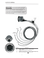
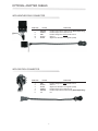
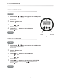
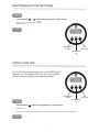
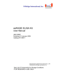
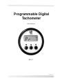
Programmable Digital
Tachometer
USER MANUAL
REV. 7
08-10001-10500
TABLE OF CONTENTS
PARTS IDENTIFICATION........................................................................ 1
BUTTON FUNCTIONS
VIEW BATTERY VOLTAGE......................................................................................... 1
VIEW TOTAL HOURS................................................................................................. 1
DISABLE OUTPUTS................................................................................................... 1
OUTPUT WIRING.........................................................................................2
OPTIONAL ADAPTER CABLES
WITH WEATHER-PACK CONNECTOR...................................................................... 3
WITH DEUTSCH CONNECTOR................................................................................. 3
PROGRAMMING
SINGLE OUTPUT MODELS........................................................................................4
DUAL OUTPUT MODELS........................................................................................... 4
RESTORING FACTORY SETTINGS.............................................. 5
SCROLL FEATURE..................................................................................... 5
TROUBLE SHOOTING............................................................................. 6
i
Thoroughly read and understand all information presented in this manual before using your digital
control.
NOTICE:
The information contained in this manual is subject to change without notice.
LOR Manufacturing shall not be liable for errors contained herein or for consequential damages in
connection with the furnishing, performance, or use of this material.
CAUTION
DISCONNECT FROM BATTERY BEFORE WELDING
ON MACHINE. FAILURE TO DO THIS MAY CAUSE
DAMAGE TO ELECTRONIC COMPONENTS, THUS
VOIDING WARRANTY.
TWO YEAR WARRANTY
LOR Manufacturing Co., Inc., for two years from the date of shipment of this item from LOR
Manufacturing Co., Inc. facilities, will repair or replace the item from LOR Manufacturing Co., Inc. (FOB
Weidman, MI U.S.A.) if it should prove to be defective in materials or workmanship. This warranty does
not cover damage resulting from mishandling in transit, vandalism, misuse, abuse, acts of nature,
alteration or lack of reasonable care. LOR Manufacturing Co., Inc. does not assume, and is not
responsible for any real or consequential damages from claims against the performance of our product,
nor is it liable for any cost related to loss of life, property, or revenue. Further, LOR Manufacturing Co.,
Inc. is in no way responsible for installation of our product, and will assume no cost of reinstallation or
removal. LOR Manufacturing Co., Inc. warranty is in lieu of all other warranties expressed or implied.
You should test your entire system daily to ensure that all components are working properly.
No implied warranty of merchantability or fitness for a particular purpose shall extend beyond two years
from date of shipment. The liability of LOR Manufacturing Co., Inc., under any such implied warranty
and under this limited warranty shall be limited to the repair or replacement of defective parts within two
years of date of shipment. LOR Manufacturing Co., Inc. shall not be liable for any incidental or
consequential damages. Some states do not allow limitations of incidental or consequential damages,
so the above limitations or exclusions may not apply to you. This warranty gives you specific rights, and
you may also have other rights which vary from state to state.
ii
PARTS IDENTIFICATION
Red LED
(lights when Output 1 is activated)
WING NUTS
LCD
DISPLAY
BEZEL
FACE
PLATE
MOUNTING
BRACKET
DOWN
BUTTON
UP
BUTTON
SET
BUTTON
OUTPUT
RECEPTACLE
HOUSING
CAN
BUTTON FUNCTIONS
VIEW BATTERY VOLTAGE
= Press and hold
+
Image above is an example of a 12 Volt gauge display. Actual voltage displayed by your
gauge may vary.
VIEW TOTAL HOURS
= Press and hold
DISABLE OUTPUTS
= Press and hold
for 4 seconds.
In this mode the LCD will alternate displaying engine RPMs for 9 to 10 seconds and “off” for
1 second. To revert to ENABLED OUTPUTS simply press
once.
1
OUTPUT WIRING
IMPORTANT: It is of the utmost importance that the digital
control be connected to a clean power source. The clean power
source can or could include (first choice) the accessory side of the
keyswitch or (second choice) the run side of the keyswitch.
A clean power source is the result of filtering unwanted voltage spikes
and EMF. Spikes can be prevented by the installation of clamping
diodes at their source (coils).
7.5 AMP
FUSE
RED
GREEN
BROWN
WHITE
(Dual Output Only)
BLACK
A
E
D
B
C
POSITION
A
B
C
D
E
=
=
=
=
=
FUNCTION
WHITE - Signal from alternator or magnetic pickup
BLACK - Ground
GREEN - Positve Output #1 to solenoid coil
BROWN - Positive Output #2 to solenoid coil (Dual Output Only)
RED - Positve Voltage from clean power source
2
OPTIONAL ADAPTER CABLES
WITH WEATHER-PACK CONNECTOR
POSITION
D C B A
D
C
B
A
COLOR
FUNCTION
BROWN
GREEN
RED
BLACK
WHITE
Positive Output #2 to solenoid coil (Dual Output Only)
Positve Output #1 to solenoid coil
Positve voltage from clean power source
Ground
Signal from alternator or magnetic pickup
WITH DEUTSCH CONNECTOR
1
2
3
6
5
4
POSITION
1
2
3
4
5
6
COLOR
FUNCTION
RED
BLACK
WHITE
GREEN
BROWN
n/a
Positve voltage from clean power source
Ground
Signal from alternator or magnetic pickup
Positve Output #1 to solenoid coil
Positive Output #2 to solenoid coil (Dual Output Only)
n/a
3
PROGRAMMING
SINGLE OUTPUT MODELS
1.
Press and hold
+
Continue to hold until display reads
Release buttons.
2.
Press the
while turning ignition key to “ON” position.
0
button once.
Release button.
3.
4.
Use the
or
Press the
button.
Use the
or
Press the
button.
button to set the HI RPM Value.
button to set the Lo RPM Value.
INCREMENT
DOWN
SET
BUTTON
INCREMENT
UP
DUAL OUTPUT MODELS
1.
Press and hold
+
Continue to hold until display reads
Release buttons.
2.
Press the
while turning ignition key to “ON” position.
0
button once.
Release button.
3.
4.
5.
Use the
or
Press the
button.
Use the
or
Press the
button.
Use the
or
button to set the HI RPM Value.
button to set the Lo RPM Value.
button to set the value for the BACK-UP TIME.
Increments are in tenths of a second (example:
Press the
button.
= 3 tenths of a second).
4
RESTORING FACTORY SETTINGS
Press and hold
+
Continue to hold until display reads
Release buttons.
while turning ignition key to “ON” position.
”dEF”
INCREMENT
DOWN
SET
BUTTON
INCREMENT
UP
SCROLL FEATURE
The Scroll Feature briefly displays each of the OEM Program
settings once. This allows the user to view every parameter
without risking an inadvertent programming change.
INCREMENT
DOWN
SET
BUTTON
INCREMENT
UP
Press and hold
while turning ignition key to “ON” position.
Release buttons.
After each of the OEM Program settings have been displayed once, the gauge reverts back to normal operation.
5
TROUBLE SHOOTING
NOTE: Test Lights are not acceptable for trouble shooting
electronic equipment because they can’t give an accurate indication of
what is happening. We suggest using a Digital Multi-meter such as the
Radio Shack p/n 22-805 or the Fluke p/n 112.
PROBLEM:
CAUSE:
SOLUTIONS:
No display
Gauge not getting power.
Check continuity of RED wire to clean power
source.
Check 7.5 Amp fuse.
Feed does not re-engage after
stopping.
Gauge not properly grounded.
Check continuity of BLACK wire to ground
connection.
Engine RPM not reaching HI set point
on gauge.
Check for stretched or out of adjustment
throttle cable - it may not allow engine to
reach HI RPM setting.
Check HI RPM setting on gauge to make
sure it is not set too close to the top RPM of
engine. (HI setting should be 150-200 RPM
below top engine RPM.)
Gauge won’t set properly.
Engine not running.
Normal operating condition.
WHITE wire not connected.
Check connection of WHITE wire to
Alternator or Magnetic Pick-up.
Open connection in WHITE wire.
Check continuity of WHITE wire from
connector at gauge to Alternator or Magnetic
Pick-up.
No Signal from Alternator.
Check for at least 3.5 VAC output at idle and
10-12 VAC at HI RPM.
No Signal from Magnetic Pick-up.
Check for 6-7 VAC at idle and 17-20 VAC at
HI RPM. Remove, clean off Magnetic Pick-up
and re-adjust pick-up per manufacturer
specification.
Magnetic Pick-up open.
Check resistance of Magnetic Pick-up.
Datcon = 130-150 ohms
(Should not be an open circuit.)
Error made during programming
sequence.
Restore Factory Settings. See page 5 of this
manual.
For further technical assistance call 1-866-644-8622.
6
LOR Manufacturing Company, Inc.
Weidman, MI 48893