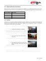
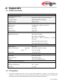
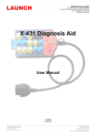
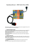
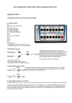
1
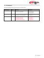
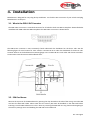
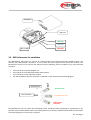
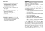
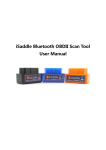
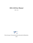
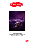
User Manual
Contents
1.
Introduction................................................................................................................................ 2
1.1. MtrackScout OBD-II Compliant ........................................................................................................... 2
2.
Hardware Features .................................................................................................................... 2
2.1.
2.2.
2.3.
2.4.
2.5.
3.
Installation .................................................................................................................................. 4
3.1.
3.2.
3.3.
3.4.
3.5.
4.
OBD-II Protocol.................................................................................................................................. 2
Micro USB Connection ....................................................................................................................... 2
Buzzer............................................................................................................................................... 2
Power Supply .................................................................................................................................... 2
LED Indication ................................................................................................................................... 3
What is the OBD-II DLC Connector..................................................................................................... 4
SIM Card Access ............................................................................................................................... 4
GPS Performance for Installation ........................................................................................................ 5
Simple Verification of Installation......................................................................................................... 6
Security ............................................................................................................................................ 6
Appendix..................................................................................................................................... 7
4.1. Hardware Specification ...................................................................................................................... 7
4.2. FCC Regulations ............................................................................................................................... 7
4.3. RF Exposure Information ................................................................................................................... 8
Page | 1
1. Introduction
The MtrackScout GPS Tracking Device is the most advanced and economical diagnostic device for communicating
vehicle information to the GSM/GPRS networks. With an integrated high sensitivity GPS receiver, the
MtrackScout provides the fundamental functions with optional advanced features for tracking light trucks and
passenger vehicles in need of monitoring location, speed, and many other codes available on the OBD port of
the vehicle.
1.1. MtrackScout OBD-II Compliant
OBD-II is a standard that was created by SAE (Society of Automotive Engineers) in the early 1990s. However,
some vehicles do not follow this standard. Therefore MtrackScout cannot guarantee the OBD-II performance of
the MtrackScout with every vehicle. For more information about MtrackScout’s OBD-II compliance, please refer to
MtrackScout OBD-II Compliance Guide document.
2. Hardware Features
2.1. OBD-II Protocol
There are five signaling protocols that are permitted with the OBD-II interface. Most vehicles have been issued
with only one of the protocols. The MtrackScout features a superior protocol detection algorithm that ensures
the device connects reliably even to vehicles that do not fully conform to the OBD-II standards. The
MtrackScout supports all legislated OBD-II protocols below:
•
•
•
•
•
J1850 PWM (Ford vehicles)
J1850 VPW (GM vehicles)
ISO9141-2 (Asian, European, Chrysler vehicles)
ISO 14230-4 KWP
ISO 15765-4 CAN (11/29 bit ID,250/500 Kbaud)
2.2. Micro USB Connection
The Micro USB can supply power to the MtrackScout device for parameter setting or firmware upgrade
purpose. When micro USB is connected to your laptop/PC and mains power is not applied, the OBD-II and
GSM/GPRS functions will be turned off temporarily. This function is used by MtrackScout technical support
staff.
2.3. Buzzer
The internal buzzer of the MtrackScout can be configured to be triggered by any number of events (speeding,
excessive idling, harsh braking or acceleration and RPM). The buzzer also indicates the operational status of the
MtrackScout explained in section 3.5 of this manual.
2.4. Power Supply
The MtrackScout device connects to the OBD-II SAE J1962 connector of the vehicle and draws power from the
OBD port. No additional power cabling is required for operation.
Ver 2.0 Page 2
2.5. LED Indication
The following table describes the LED operation of the MtrackScout:
LED Indicators
Color
Green
LED Status
Solid OFF Fast blinking
Blinking every 10 seconds
Description
OBD Protocol not found OBD-II
data transmission.
Deep sleep mode
OBD
GPS
Blue
Solid OFF
Blinking every 1 second Solid ON
GPS power OFF GPS not fix
GPS Location Fix
GSM
Red
OFF
Blinking every 1 second
Blinking every 2 seconds
Blinking twice every 2 second
GSM Power OFF
GSM no signal
GSM registered
GPRS connected
Ver 2.0 Page 3
3. Installation
MtrackScout is designed for easy Plug & Play installation. Just find the DLC connector of your vehicle and plug
MtrackScout in to the port.
3.1. What is the OBD-II DLC Connector
The OBD-II DLC connector is a standard connector for all vehicles which are OBD-II compliant. Almost all vehicles
manufactured in 1996 or later are OBD-II compliant. The OBD-II DLC connector is shown below:
The OBD-II DLC connector is most commonly found underneath the dashboard on the driver side. See the
following figure for DLC location for most vehicles. Location #1-#3 is under the dashboard of the driver side.
Location #4-#5 is on the dashboard instrument/gauge area. Location #6-#7 is near radio and climate controller.
Location #8 is near the armrest and handbrake area.
3.2. SIM Card Access
Remove the top cover of the MtrackScout by pressing the clips located on the side of the casing. Insert the SIM
card into the SIM card holder. Please note that the security PIN must be disabled on the SIM card before
inserting it into the MtrackScout unit. This is done my inserting the SIM card into any phone and navigating to
the security settings menu and disabling the PIN code on the SIM card.
Ver 2.0 Page 4
Top Cover
SIM Card
OBD LED
GPS LED
GSM LED
Micro USB
3.3. GPS Performance for Installation
The MtrackScout determines its position by communicating with Global Positioning Satellites (GPS). The
accuracy of the GPS location will have a lot to do with the overall performance of the GPS receiver. The
MtrackScout device has an internal GPS antenna and the following interior conditions may cause bad GPS
reception:
•
•
•
•
Your vehicle has a metallic window tint
Your vehicle has a windshield mounted radio antenna
Your vehicle has a solar reflective window
The AX5 installation direction should be considered as well. Please see the following figure:
Sky
GPS Antenna
Good for GPS
reception
DLC Connector
Acceptable for GPS
Bad for GPS
reception
The MtrackScout uses the latest GPS technology which accelerates GPS positioning by capitalizing on the
periodic nature of GPS satellite orbits. GPS orbit predictions are directly calculated by the GPS receiver and no
external aiding data or connectivity is required.
Ver 2.0 Page 5
3.4. Simple Verification of Installation
When the device is configured and first plugged into the OBD port. The MtrackScout will have some buzzer
indications for basic function test. The user can simply to verify if the MtrackScout device is installed properly.
Buzzer Indication
Beep 1 time
Description
Device Power ON
Beep 2 times
OBD Protocol Connected
Beep 3 times
GSM/GPRS Connected
Beep 4 times
GPS Fix
3.5. Security
Once the unit is installed the flashing LED lights might be visible due to the location of the OBD-II DLC
connector on the dash board. If this is the case we suggest that the LED lights are covered / concealed by
sticking a piece of black tape over the LED lights.
•
LED Lights are visible after installation.
•
Cover the LED lights with a piece of black
sticky tape.
•
After applying the black sticky tape the LED
Lights are no longer visible when active in the
vehicle.
Ver 2.0 Page 6
4. Appendix
4.1. Hardware Specification
MtrackScout
GSM/GPRS Specification
GSM Module
Quad band (850/900/1800/1900MHz)
Communication
SMS/USSD/GPRS /TCP/UDP
GSM Antennas
Internal Type
GPS Specification
GPS Receiver
50 Channels, L1 Band, C/A Code
Sensitivity
-159dBm
Accuracy
2.5m CEP
Assisted GPS
Supported
OBD-II Specification
Supported Protocol
ISO 15765-4 (CAN)
ISO 14230-4 (KWP2000)
ISO 9141-2
vehicles)
(Asian,
European,
Chrysler
SAE J1850 VPW (GM vehicles)
SAE J1850 PWM (Ford vehicles)
Electrical Characteristics
Power Source
8-20 VDC
Power Consumption
Sleep
Deep Sleep
Operation
al
140 mA @ 12VDC (Average)
18 mA @ 12VDC
<2 mA @ 12VDC
Mechanical Specification
Dimension
50 x 46 x 25 mm
OBD Connector
SAE J1962 Type A
Weight
54g (Include OBD Option)
Environmental Characteristics
Operation Temperature
-25 ~ +70°C
Storage Temperature
-40 ~ +85°C
Humidity
5 ~ 95%
4.2. FCC Regulations
•
This device complies with part 15 of the FCC Rules. Operation is subject to the following two
conditions: (1) This device may not cause harmful interference, and (2) this device must accept any
interference received, including interference that may cause undesired operation.
Ver 2.0 Page 7
•
This device has been tested and found to comply with the limits for a Class B digital device, pursuant to
Part 15 of the FCC Rules. These limits are designed to provide reasonable protection against harmful
interference in a residential installation. This equipment generates, uses and can radiate radio
frequency energy and, if not installed and used in accordance with the instructions, may cause harmful
interference to radio communications. However, there is no guarantee that interference will not occur
in a particular installation. If this equipment does cause harmful interference to radio or television
reception, which can be determined by turning the equipment off and on, the user is encouraged to
try to correct the interference by one or more of the following measures:
Reorient or relocate the receiving antenna.
Increase the separation between the equipment and receiver.
Connect the equipment into an outlet on a circuit different from that to which the
receiver is connected.
Consult the dealer or an experienced radio/TV technician for help.
Changes or modifications not expressly approved by the party responsible for compliance could void the user’s
authority to operate the equipment.
4.3. RF Exposure Information
This device meets the government’s requirements for exposure to radio waves.
This device is designed and manufactured not to exceed the emission limits for exposure to radio
frequency (RF) energy set by the Federal Communications Commission of the U.S. Government.
This device complies with FCC radiation exposure limits set forth for an uncontrolled environment. In order to
avoid the possibility of exceeding the FCC radio frequency exposure limits, human proximity to the antenna
shall not be less than 20cm during normal operation.
Ver 2.0 Page 8