1
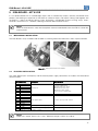
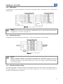
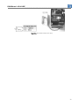
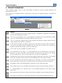
Motors | Energy | Automation | Coatings
Soft-Starter
SSW-06 V1.6X
Multimotor Application Guide
Language: English
Document: 10000603753 / 00
Multimotor Application Guide
Series: SSW-06 V1.6X
Language: English
Document Nr: 10000603753 / 00
Publication date: 08/2009
Index___________________________________________________________________________
INDEX
ABOUT THE MANUAL................................................................................... 6
ABREVIATIONS AND DEFINITIONS ........................................................................................................... 6
NUMERICAL REPRESENTATION ............................................................................................................... 6
1 INTRODUCTION TO THE MULTI MOTOR CONTROL ........................... 7
1.1
PARALLEL MULTIMOTOR................................................................................................................ 7
1.2
CASCADE MULTIMOTOR................................................................................................................. 7
1.2.1
Advantage................................................................................................................................... 8
1.2.2
Disadvantages............................................................................................................................ 8
2 SSW-06 MULTIMOTOR CONTROL......................................................... 9
2.1
2.2
ADVANTAGES.................................................................................................................................... 9
DISADVANTAGES.............................................................................................................................. 9
3 SOFTPLC FUNCTION ............................................................................ 10
3.1
MMC FUNCTION BLOCK – MULTIMOTOR CONTROL ............................................................... 10
3.1.1
Used Motors ............................................................................................................................. 10
3.1.2
Inputs ........................................................................................................................................ 10
3.1.2.1
Two-wire............................................................................................................................ 11
3.1.2.2
Three-wire ......................................................................................................................... 11
3.1.2.3
Protection .......................................................................................................................... 11
3.1.3
Outputs ..................................................................................................................................... 12
3.1.3.1
Start-Stop Output ............................................................................................................. 12
3.1.3.2
By-pass Output ................................................................................................................. 12
3.1.4
Starting Data Modification ...................................................................................................... 13
3.1.4.1
Not Used Starting Data Modification.............................................................................. 13
3.1.5
Fixed Motor............................................................................................................................... 13
3.1.6
Minimal Operation Conditions................................................................................................ 14
3.2
MONITORING .................................................................................................................................. 14
4 SSW-06 SOFT-STARTER PARAMETERIZATION................................. 16
4.1
4.2
4.3
4.4
4.5
P140 – EXTERNAL BY-PASS CONTACTOR.................................................................................. 16
P220 - LOCAL/REMOTE SOURCE SELECTION ........................................................................... 16
P621 – CLOSED BY-PASS CONTACTOR...................................................................................... 16
P950 – ENABLE SOFTPLC.............................................................................................................. 16
P951 – DIGITAL INPUT AND OUTPUT EXPANSION BOARD ENABLING................................... 17
5 IOS6 BOARD – KIT K-IOE...................................................................... 18
5.1
MECHANICAL INSTALLATION....................................................................................................... 18
5.2
ELECTRIC INSTALLATION ............................................................................................................. 18
5.2.1
Digital Inputs ............................................................................................................................ 19
5.2.2
Digital Relay Outputs............................................................................................................... 19
5.2.3
IOS6 External Power Supply ................................................................................................... 19
6 PROJECT EXAMPLES ........................................................................... 21
6.1
PROJECT 1 – TWO MOTOR SEQUENTIAL CASCADE ................................................................ 23
6.1.1
SoftPLC Project 1 .................................................................................................................... 23
6.1.2
Project 1 Electric Diagram...................................................................................................... 24
6.2
PROJECT 2 – THREE MOTOR SEQUENTIAL CASCADE............................................................. 25
6.2.1
SoftPLC Project 2 .................................................................................................................... 25
6.2.2
Project 2 Electric Diagram...................................................................................................... 26
6.3
PROJECT 3 – THREE MOTOR FIXED SEQUENTIAL CASCADE ................................................. 27
6.3.1
SoftPLC Project 3 .................................................................................................................... 27
4
Index___________________________________________________________________________
6.3.2
Project 3 Electric Diagram...................................................................................................... 28
6.4
PROJECT 4 – THREE MOTOR INDIVIDUAL CASCADE ............................................................... 29
6.4.1
SoftPLC Project 4 .................................................................................................................... 29
6.4.2
Project 4 Electric Diagram...................................................................................................... 30
6.5
PROJECT 5 - MULTIPUMP............................................................................................................. 31
6.5.1
Multipump System ................................................................................................................... 31
6.5.2
SoftPLC Project 5 .................................................................................................................... 31
6.5.3
Project 5 Electric Diagram...................................................................................................... 32
5
About the Manual________________________________________________________________
ABOUT THE MANUAL
This manual provides the necessary information for the operation of the SSW-06 soft-starter, used in the
multimotor application, with the IOS6 digital input and output expansion board and programmed in ladder
language. This manual must be used together with the SSW-06 user manual, SoftPLC manual and the WLP
software.
ABREVIATIONS AND DEFINITIONS
PLC
RAM
WLP
USB
Programmable Logic Controller
Random Access Memory
Ladder language programming software
Universal Serial Bus
NUMERICAL REPRESENTATION
Decimal numbers are represented by means of digits without suffix. Hexadecimal numbers are represented with
the letter ‘h’ after the number.
6
Introduction To The Multimotor Control__________________________________________
1 INTRODUCTION TO THE MULTI MOTOR CONTROL
Soft-starter multimotor control consists in starting more than one motor with the same soft-starter. It is still used
in the industry with the purpose of reducing the cost of the motor starting system. It can be implemented in two
ways, in parallel or in cascade.
1.1
PARALLEL MULTIMOTOR
All the motors are connected in parallel, starting and stopping simultaneously
Figure 1.1: Parallel multimotor
The soft-starter must be selected in order to withstand the sum of the individual motor currents for both the
starting and the continuous operation. It is feasible for low power applications where the motor costs are less
than the soft-tarter cost. All the soft-starters allow this type of application.
Some of the soft-starter protections can be used, phase loss for instance – if the detection is carried out
through the voltage monitoring, others like overload, must be performed by means of individual overload relays
for each motor.
1.2
CASCADE MULTIMOTOR
The soft-starter is used to start each motor individually, which is then connected directly to the line. The
cascade starting can be performed in two forms: In sequence - the motors are started in a sequence, one after
another, and stopped simultaneously - or individually - the motors are started and stopped individually.
Figure 1.2: Cascade multimotor
The soft-starter must be selected to withstand the duty cycles of the motors, i.e., the starting current and time,
and the number of starts per hour considering all the motors.
7
Introduction To The Multimotor Control__________________________________________
It requires auxiliary contactors for controlling the motors. The contactors K2, K4 and K6 are used to start the
motors individually through the soft-starter, while K3, K5 and K7 are used to connect the motors to the line after
their starting.
The majority of the most advanced soft-starters on the market do not allow this type of application because they
are every time more focused in the protection of the electric motor and the electric installation, and not only in
starting the motors.
1.2.1
Advantage
■ Reduction of the driving system cost, by using only one soft-starter for starting more than one motor, in cases
when the soft-starter cost is significant compared to the cost of entire motor driving system.
1.2.2
Disadvantages
■ The motor protections implemented in the soft-starter are not used.
■ The need of protections like overload relays, phase loss relays, fuses, etc., for every driven motor.
■ It only allows the starting of the motors, but does not allow their controlled stopping in applications like
centrifuge hydraulic pumps.
■ It uses the same starting data for all the motors, which limits its use to identical motors.
■ Complex motor driving system, because of the wiring, contactors, timers or PLCs used.
8
SSW-06 Multimotor Control______________________________________________________
2 SSW-06 MULTIMOTOR CONTROL
It is achieved by using an SW-06 soft-starter with the IOS6 board from the K-IOS kit in cascade multimotor
applications.
2.1
ADVANTAGES
■ It makes it possible to control up to three motors with only one SSW-06 soft-starter.
■ Starting and stopping in a sequential cascade or individually.
■ It allows the modification of some of the starting characteristics, by means of the modification of up to three
parameters for each of the three motors, for instance, starting current and motor current. Therefore, it makes
the starting of three different motors possible, within a range from 30 % to 100 % of the SSW-06 soft-starter
rated current.
■ By allowing the controlled starting and stopping of the driven motors, it makes the use with centrifuge
hydraulic pumps possible.
■ A reduction in installation and maintenance costs due to the simplicity of the motor driving system,
implemented inside the SSW-06 by means of the IOS6 board and the SoftPLC software.
■ Easy implementation and modification of functions and protections through the SoftPLC, by using the project
software WLP.
2.2
DISADVANTAGES
■ Many of the motor protections implemented in SSW-06 soft-starters are not used.
■ The need of protections like overload relays, phase loss relays, fuses, etc., for every driven motor.
9
SoftPLC Function_______________________________________________________________
3 SOFTPLC FUNCTION
The SSW-06 has the capacity to implement the SoftPLC, a programable logic controller software with contact
language - Ladder - and the possibility 1 k byte of applicative software.
With the SoftPLC, interlocking logics, between digital and analog inputs and outputs, for driving motors, among
other logics, can be created. SoftPLC is programmable through the WLP software. This software also allows
on-line monitoring of the applicative program developed by the user, which facilitates its development.
The WLP software comes for free together with the SSW-06 soft-starter and can also be downloaded from
WEG’s website. Information on its use can be obtained in the SSW-06 WLP software manual.
3.1
MMC FUNCTION BLOCK – MULTIMOTOR CONTROL
A function block called Multimotor Control (MMC) has been developed for the multimotor control system, which
together with the IOS6 board allows the automatic control of up to three motors.
Input:
EN:
Enables the block
Output:
ENO:
Indicates that the block is active
Properties:
Motor1, 2 or 3
START:
Starts the motor in 1
STOP:
Stops the motor in 0
FAULT:
Stops the motor in 0
STARTING: Indicates motor starting or stopping
BYPASS:
Indicates active by-pass
SRC1:
Data source
SRC2:
Data source
SRC3:
Data source
DST1:
Data destination
DST2:
Data destination
DST2:
Data destination
Figure 3.1: MMC function block
3.1.1
Used Motors
The block is divided into three sub-blocks, Motor 1, Motor 2 and Motor 3, with each motor characteristics.
Initially, the not used motors must be disabled in the block, by means of the properties of each motor. In order
to get access to these properties, double-click on the block.
Figure 3.2: Not used Motor 3
3.1.2
Inputs
The control logic for each motor is performed based in three inputs: Start, Stop and Fault. Those inputs make
different types of control logics possible, either two-wire or three-wire start/stop commands.
10
SoftPLC Function_______________________________________________________________
3.1.2.1
Two-wire
In the example below the digital input 7 (DI7 = Start/Stop) of the IOS6 board starts the Motor 1 when closed
and stops it when opened. The inputs Start, Stop and Fault are programmed as the same DI.
Figure 3.3: Two-wire control
3.1.2.2
Three-wire
In the example below the digital input 7 (DI7 = Start) of the IOS6 board starts the Motor 1 when pressed to
close, and the digital input 8 DI8 = Stop) stops it when pressed to open. The inputs Stop and Fault are
programmed as the same DI.
Figure 3.4: Three-wire control
3.1.2.3
Protection
In the example below the digital input 9 (DI9 = Fault) allows the installation of any type of protection, which
disables the motor when it opens. The Fault input only disables the motor or prevents its starting, but it does not
cause a SSW-06 soft-starter fault.
Figure 3.5: Protection input
11
SoftPLC Function_______________________________________________________________
One example is the installation of a motor temperature sensor, which by tripping stops the motor and after
cooling down allows the motor start again.
Another example is the installation of level sensors (floating level switches) with centrifuge pump applications.
When the level is too high or too low, then the level sensors will trip stopping the motor, and when the correct
level is restored, allow the motor start again.
Figure 3.6: Protection examples
3.1.3
Outputs
They are used to control the power contactors that will connect the motors to the soft-starter during their start
and stop stages, and to connect them to the supply line, when necessary, releasing the soft-starter.
3.1.3.1
Start-Stop Output
It is used to connect the motor to and disconnect it from the SSW-06 soft-starter, during the start and stop
stages. In the figure 3.7 example the digital output 4 (RL4 = Starting) controls the contactor K2, which is
responsible for the connection of the M1 motor to the soft-starter during the start and stop stages.
3.1.3.2
By-pass Output
It is used to connect the motor directly to the supply line after its starting. In the figure 3.7 example the digital
output 5 (RL5 = By-pass) controls the contactor K3, which is responsible for the connection of the M1 motor to
the supply line after its starting.
Figure 3.7: Start-stop and by-pass outputs
12
SoftPLC Function_______________________________________________________________
3.1.4
Starting Data Modification
The MMC block allows the modification of up to three pieces of data for each motor. This data is loaded from
the source into the destination (Source 1, 2 and 3 into Destin 1, 2 and 3), during every starting and stopping of
the respective motor. In the example below the M1 motor current P401 is loaded with 100.0 A (1000) and the
current limit is loaded with 2.7 x In of the motor (270).
Figure 3.8: M1 motor data change
3.1.4.1
Not Used Starting Data Modification
When there is no data modification from one motor to another, a word marker must be reserved as destination.
In the example below the Word Marker %MW 8000 has been reserved. All the used motors can use this same
word marker.
Figure 3.9: Not used data change
3.1.5
Fixed Motor
Through this property it can be determined if, after the drive of the last motor, the SSW must be by-passed
through the contactor of by-pass or if it must keep supplying the motor. Some restrictions for the use of this
property exist, as: only the last motor of the sequence can be fixed; all the motors must be turn on or turn off in
the same instant; the fault protections must be turn off all the motors. In item 6.3 am use example is shown.
Figure 3.10: Fixed Motor 3
13
SoftPLC Function_______________________________________________________________
3.1.6
Minimal Operation Conditions
An example showing the starting of two motors with three-wire command, using the digital inputs 7 and 8 for
the M1 motor, and 9 and 10 for the M2 motor.
Figure 3.11: Minimal operation conditions
In order to start-up this example, simply follow the next steps:
■ Insert a coil for the soft-starter General Enable via SoftPLC, %SX3003: 1 = General Enable.
■ Insert the MMC function block.
■ Enable the MMC block at the EN input.
■ Insert a coil at the MMC block output - ENO - and reserve a bit marker %MX5000 for this coil.
■ Program the MMC block properties.
■ The following parameters must be changed: P140 = 1, P220 = 9, P621 = 0, P950 = 1 and P951 = 1. These
parameters are detailed in the next chapter.
■ Compile the project and transfer it to the soft-starter.
3.2
MONITORING
The WLP has “on-line” monitoring of the applicative software developed for the SoftPLC, which makes the
development and debugging of the project easier. The monitoring of the digital inputs and outputs is showed in
the figure 3.12.
Figure 3.12: Monitoring of the digital inputs and outputs
The monitoring of an MMC block is showed in the figure 3.13.
14
SoftPLC Function_______________________________________________________________
Figure 3.13: Monitoring of an MMC block
15
SSW-06 Soft-Starter Parameterization____________________________________________
4 SSW-06 SOFT-STARTER PARAMETERIZATION
The parameters related to the multimotor control using the IOS6 board from the SSW-06 soft-starter K_IOS6
kit, are described next.
4.1
P140 – EXTERNAL BY-PASS CONTACTOR
It is used in this application to indicate to the SoftPLC that an external by-pass contactor will be used, 1 =
active.
Range
0 = Inactive
1 = Active
Factory setting
1 = Inactive
Access
Reading / writing
■ 0 – Inactive: Without external by-pass contactor
■ 1 – Active: With external by-pass contactor
4.2
P220 - LOCAL/REMOTE SOURCE SELECTION
It must be programmed in order to allow the control of the motors via SoftPLC, 9 = SoftPLC Local.
Range
0 = Always Local
1 = Always Remote
2 = HMI (L)
3 = HMI (R)
4 = Digital inputs DI4 to DI6
5 = Serial (L)
6 = Serial (R)
7 = Fieldbus (L)
8 = Fieldbus (R)
9 = SoftPLC Local
10 = SoftPLC Remote
4.3
Factory setting
2 = HMI (L)
Access
Reading / writing
P621 – CLOSED BY-PASS CONTACTOR
It is used in this application to make it possible the disabling of the by-pass contactor closed/short-circuit
protection. In this application the protection would trip due to the short-circuit made by the external by-pass
contactor controlled by the SoftPLC, which has not been opened in the instant the SSW-06 soft-starter was
removed from the circuit after starting one of the motors.
Range
0 = Inactive
1 = Active
Factory setting
1 = Active
Access
Reading / writing
■ 0 – Inactive: It makes it possible the use of the SSW-06 soft-starter in multimotor control applications.
■ 1 – Active: Active protection, it is the factory default setting.
NOTE!
Deactivate this protection only to make the SSW-06 use in multimotor applications possible, i.e.,
when the SSW-06 drives more than one motor.
4.4
P950 – ENABLE SOFTPLC
It allows enabling the execution of the SoftPLC user applicative software, 1 = Yes.
Range
0 = No
1 = Yes
Factory setting
0 = No
Access
Reading / writing
■ 0 – No: Disabled SoftPLC applicative
16
SSW-06 Soft-Starter Parameterization____________________________________________
■ 1 – Yes: Enabled SoftPLC applicative
4.5
P951 – DIGITAL INPUT AND OUTPUT EXPANSION BOARD ENABLING
Its function is to enable the K-IOE kit digital inputs and outputs expansion board IOS6. This board can only be
used through the SoftPLC, 1 = Yes.
Range
0 = No
1 = Yes
Factory setting
0 = No
Access
Reading / writing
■ 0 – No: IOS6 board disabled
■ 1 – Yes: IOS6 board enabled
17
IOS6 Board – Kit K-IOE__________________________________________________________
5 IOS6 BOARD – KIT K-IOE
It is an optional board with six isolated digital inputs and six isolated relay outputs, internally connected to the
product, and allowing the expansion of the SSW-06 number of inputs and outputs. Being used together with
the SoftPLC, it allows the electric driving system, eliminating a considerable amount of wiring, relays, timers,
contactors and micro PLCs. Therefore, reducing installation and maintenance costs.
NOTE!
When the IOS6 board is used, then the optional communication boards from the KFB kits cannot be
used anymore.
5.1
MECHANICAL INSTALLATION
The IOS6 board is easily installed inside the SSW-06, allowing mechanical robustness and a simple installation.
Figure 5.1: IOS6 board mechanical installation
5.2
ELECTRIC INSTALLATION
The signal (digital inputs and outputs) and the external power supply connections are made at the IOS6 board
terminal strip X4.
X4 terminal strip
Description
1
DI7
2
DI8
3
DI9
Digital inputs
4
DI10
5
DI11
6
DI12
7
DI COM
Common point for the digital inputs
8
RL4 NO
9
RL5 NO
10
RL6 NO
Relay digital outputs
11
RL7 NO
12
RL8 NO
13
RL9 NO
14
RL COM
Common point of the relay outputs
15
+24Vdc
Board external power supply input
16
0Vdc
NO = Normally open contact, COM = Common
Specifications
6 isolated digital inputs
Minimum high level: 18Vdc
Maximum low level: 3Vdc
Maximum Voltage: 30Vdc
Input Current: 11mA@ 24Vdc
To be used only for the digital inputs
Contact capacity: 1A @ 240 Vac
To be used only for the relay outputs
24 Vdc, (20 to 30 Vdc / 150 mA)
NOTE!
Cable cross section, from 0.5 to 1.0 mm2. Maximum torque: 0.50N.m (4.50 lbf.in).
18
IOS6 Board – Kit K-IOE__________________________________________________________
5.2.1
Digital Inputs
The digital inputs must be activated with an external 24 Vdc power supply, using either 0 V or +24 Vdc as the
common point.
Figure 5.2: Connection diagram of the digital inputs
NOTE!
The digital inputs wiring must be made with shielded cables and must be laid separately from other
wiring (power, 110 V/220 V command, etc.).
5.2.2
Digital Relay Outputs
The digital outputs are normally open relay contacts. They close the contacts when activated.
Figure 5.3: Relay outputs diagram
NOTE!
Relays, contactors, solenoids or electromechanical brake coils connected to relay outputs can
generate interference in the control circuit. To eliminate this effect, RC suppressors must be
connected in parallel with the coils of those devices in case of AC supply, and free-wheeling diodes
in case of DC supply.
5.2.3
IOS6 External Power Supply
The IOS6 board needs to be fed externally for the operation of both the relay outputs and the digital inputs. It
should be supplied by a 24 Vdc source with current capacity higher than 150 mA. The same power supply can
be used for the digital inputs and outputs.
19
IOS6 Board – Kit K-IOE__________________________________________________________
Figure 5.4: IOS6 board external power supply
20
Project Examples_______________________________________________________________
6 PROJECT EXAMPLES
Some suggestive projects, which can be used integrally or partially to create the desired application, are
presented in this section.
Those examples are available in the WLP, listed with the same used in this application guide, as showed in the
figure below:
Figure 6.1: Accessing the WLP examples
NOTES!
The main warning notes for all of the suggestive projects, listed below, are indicated in the diagrams
by means of their respective numbers.
The use of ultra-rapid action fuses is not mandatory for the SSW-06 soft-starter operation, however,
their use is recommended for the complete protection of the thyristors.
The “T1” transformer is optional and must be used when the supply line voltage is different from the
supply voltage for the electronics and the fans.
In the event of damage in the SSW-06 power circuit that keeps the driven motor running due to
short-circuit; the motor protection is obtained with the use of the K1 contactor. This contactor must
be able to withstand the starting current of the used motors.
X1E (33 and 34) is only available in the models with fans.
For the protection of the motors, it is recommended the use of overload relays, thermistors or
thermostats, for each used motor. When thermistors or thermostats are used, they must provide
normally closed contacts, which must be wired to the Fault input of the MMC block.
Remember that when using two-wire command (single pole single throw switch) every time the power
returns after a power failure, the motor will restart immediately if the switch remains closed
In case of maintenance in the Soft-Starter SSW-06 or in the motors, it is necessary to disconnect the
power supply input, in order to assure complete isolation of the equipments from the supply line.
An emergency stop can be implemented by cutting off the system command supply.
The contactors (K2 to K7) must be able to withstand the starting current of the motors they drive.
It is recommended to use slow blow fuses for the individual protection of the motors against
short-circuits.
Verify whether the relay outputs have the current capacity required to switch the power contactors.
The supply must come from a 24 Vdc power supply with a current capacity higher than 150 mA.
21
Project Examples_______________________________________________________________
It is recommended to use slow blow fuses for the protection of the complete system against shortcircuits. These fuses must withstand the total current consumed by the system, plus the starting
current of the biggest driven motor.
Project a circuit breaker for the protection of the control circuit and the interruption of the supply to
the K1 contactor coil.
The K1 contactor will be switched off when the SSW-06 indicates an error, thus protecting the driving
system. This contactor must be able to withstand the starting current of the biggest motor and the
current of the other motors running simultaneously.
22
Project Examples_______________________________________________________________
6.1
PROJECT 1 – TWO MOTOR SEQUENTIAL CASCADE
Example with the control of two motors in cascade - starting sequentially one after the other.
It comprises:
■ two motors;
■ single command – it starts always the two motors, one after the other;
■ with controlled deceleration – through the start/stop input – it stops a motor of each time;
■ without controlled deceleration – through the general enable/disable input – it stops the two motors
simultaneously by opening the contactors;
■ input fault – it stops the motor that is with fault.
6.1.1
SoftPLC Project 1
Figure 6.2: SoftPLC Project 1
Description:
■ %IX2 (SSW-06) = digital input for general enable (closed) and general disable (open);
■ %SX3003 = General Enable via SoftPLC;
■ %MX5000 = bit marker reserved for the MMC block output;
■ %IX1 (SSW-06) = start (closed) and stop (open) digital input;
■ %IX3, %IX4 (SSW-06) = Fault (closed = no fault) digital inputs;
■ %QX4, %QX6 (IOS6), starting digital outputs;
■ %QX5, %QX7 (IOS6), by-pass digital outputs;
■ %MW8000 = word marker reserved for the modification of not used parameters.
23
Project Examples_______________________________________________________________
6.1.2
Project 1 Electric Diagram
24
Project Examples_______________________________________________________________
6.2
PROJECT 2 – THREE MOTOR SEQUENTIAL CASCADE
Example with the control of three motors in cascade - starting sequentially one after the other.
It comprises:
■ three motors;
■ single command – it starts always the two motors, one after the other;
■ with controlled deceleration – through the start/stop input – it stops a motor of each time;
■ without controlled deceleration – through the general enable/disable input – it stops the three motors
simultaneously by opening the contactors;
■ input fault – it stops the motor that is with fault.
6.2.1
SoftPLC Project 2
Figure 6.3: SoftPLC Project 2
Description:
■ %IX2 (SSW-06) = digital input for general enable (closed) and general disable (open);
■ %SX3003 = General Enable via SoftPLC;
■ %MX5000 = bit marker reserved for the MMC block output;
■ %IX1 (SSW-06) = start (closed) and stop (open) digital input;
■ %IX3, %IX4, %IX5 (SSW-06) = Fault (closed = no fault) digital inputs;
■ %QX4, %QX6 (IOS6), starting digital outputs;
■ %QX5, %QX7 (IOS6), by-pass digital outputs;
■ %MW8000 = word marker reserved for the modification of not used parameters.
25
Project Examples_______________________________________________________________
6.2.2
Project 2 Electric Diagram
26
Project Examples_______________________________________________________________
6.3
PROJECT 3 – THREE MOTOR FIXED SEQUENTIAL CASCADE
Example with the control of three motors in cascade - starting sequentially M1, M2 and M3, with the motor 3
connected directly to SSW without by-pass contactor.
It comprises:
■ three motors;
■ single command – it starts always the three motors, starting sequentially M1, M2 and M3;
■ with controlled deceleration – through the start/stop input – it stops a motor of each time, sequentially M3, M2
and M1;
■ without controlled deceleration – through the general enable/disable input – it stops the three motors
simultaneously by opening the contactors;
■ input fault – it stops the motor that is with fault.
6.3.1
SoftPLC Project 3
Figure 6.4: SoftPLC Project 2
Description:
■ %IX2 (SSW-06) = digital input for general enable (closed) and general disable (open);
■ %SX3003 = General Enable via SoftPLC;
■ %MX5000 = bit marker reserved for the MMC block output;
■ %IX1 (SSW-06) = start (closed) and stop (open) digital input;
■ %IX3, %IX4, %IX5 (SSW-06) = Fault (closed = no fault) digital inputs;
■% MX5001 = bit marker reserved for the fault indication;
■ %QX4, %QX6 (IOS6), starting digital outputs;
■ %QX5, %QX7 (IOS6), by-pass digital outputs;
■ %MW8000 = word marker reserved for the modification of not used parameters.
27
Project Examples_______________________________________________________________
6.3.2
Project 3 Electric Diagram
28
Project Examples_______________________________________________________________
6.4
PROJECT 4 – THREE MOTOR INDIVIDUAL CASCADE
Example with the individual control of three motors, which allows the individual starting and stopping control of
each motor.
It comprises:
■ three motors;
■ three-wire individual command – via digital inputs (separated start and stop) for each motor;
■ without controlled deceleration – through the general enable/disable input – it stops the three motors
simultaneously by opening the contactors;
■ input fault – it stops the motor that is with fault.
6.4.1
SoftPLC Project 4
Figure 6.5: SoftPLC Project 3
Description:
■ %IX1 (SSW-06) = digital input for General Enable;
■ %SX3003 = General Enable via SoftPLC;
■ %MX5000 = bit marker reserved for the MMC block output;
■ %IX7, %IX9, %IX11 (IOS6), Start digital inputs;
■ %IX8, %IX10, %IX12 (IOS6), Stop digital inputs;
■ %IX2, %IX2, %IX4 (SSW-06), Fault digital inputs;
■ %QX4, %QX6, %QX8 (IOS6), starting digital outputs;
■ %QX5, %QX7, %QX9 (IOS6), by-pass digital outputs;
■ %MW8000 = word marker reserved for the modification of not used parameters.
29
Project Examples_______________________________________________________________
6.4.2
Project 4 Electric Diagram
30
Project Examples_______________________________________________________________
6.5
PROJECT 5 - MULTIPUMP
Example with multipump control, which makes the automatic control of three pumps, with rotation, for low
power applications.
It comprises:
■ Three motors with three centrifuge pumps;
■ Manual and automatic command: Manual - via three digital inputs (separated start/stop for each motor).
Automatic with rotation - via digital input for the level sensors;
■ Rotation: in automatic mode, at every activation via level sensors, it starts two of the three pumps;
■ Manual/automatic selection via digital input - manual mode if open and automatic when closed;
■ Manual activation is only allowed in manual mode and with closed level sensors;
■ General disable input – allows immediate stop of all the motors;
■ Phase loss protection via SoftPLC, E03, even with motors driven via by-pass;
■ Programmed automatic error reset for faults of the SSW.
6.5.1
Multipump System
Figure 6.6: Multipump system
The figure 6.4 system is often used in residential or commercial buildings where it is necessary to keep a water
reservoir full through the activation, with rotation, of two of the three used centrifuge pumps. In this system only
two pumps are necessary, and the third is a stand-by one for a case of failure, therefore, the rotation is
necessary in order to keep this pump in perfect operation conditions.
6.5.2
SoftPLC Project 5
Because of the size of this project SoftPLC applicative, it must be visualized directly in the WLP.
31
Project Examples_______________________________________________________________
6.5.3
Project 5 Electric Diagram
32