1
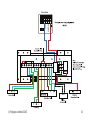
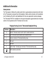
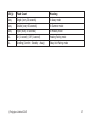
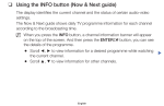
Wetroom Thermostat
Installation Instructions
Wetroom thermostat for zonal Underfloor heating temperature control for new installations
or to replace existing Polypipe wired Room thermostats in wetroom environments. Support
for up to 10 separate heating zones. Provides programmer / time clock functionality.
Requires Heating Hub Unit to operate.
IN THE BOX:
Wetroom Thermostat
Backplate
Safety Cover
© Polypipe Limited 2015
Temperature
Sensor
2 x AAA
alkaline battery
1
Introduction
This thermostat is a part of the Polypipe range of cloud connected monitoring and control
products. Its operation is dependant upon being paired to the broadband Internet connected Heating Hub Unit (supplied separately). The thermotstat provides both room thermostat
and programmer / time clock functionality.
Basic day-to-day user operation changes can be made using the three buttons. Additionally
there is comprehensive yet intuitive and easy to use control via the Polypipe web dashboard. Accessible from any Internet connected computer anywhere in the World. iPhone
and Android smartphone apps are also available for free download.
It is recommended that this product is installed by
a suitably qualified heating engineer, plumber or
electrician.
Please read the Safety Information section of this
document before proceeding.
2
© Polypipe Limited 2015
Version Information
This thermostat is battery powered with a latching relay. It has 3 control buttons - Comfort
(+), Standby and Away with associated LED indicators.
Installation Configurations Supported
This thermostat can be used in several ways to suit various heating control needs:
Thermostat Type: Wired connection Polypipe wired master or slave unit.
Multi Heating Zone Control: A single Polypipe system can support up to 10 thermostats
(one for each heating zone) in a wired configuration. This flexibility enables Polypipe to be
used to control heating systems that are Building Regulations Part L compliant and beyond.
Maximum Number of Devices: Every Polypipe device within a single system, e.g. Wetroom thermostat, Room thermostat must be paired to the Heating Hub. The Heating Hub
supports up to a maximum of 10 devices.
© Polypipe Limited 2015
3
Installation Instructions
Single or multiple heating zones
If this is a single zone heating system then simply follow these instructions. The Polypipe
system will support up to 10 heating zones. For additional thermostats simply repeat these
instructions for each one required. The web dashboard will automatically update the Heating widget with the additional device when you next log in.
STEP ONE - Install Heating Hub Unit
•
•
If you are adding heating controls to an existing Polypipe installation then please jump
to STEP THREE - Log in and follow Wizard.
If this is a new Polypipe installation then you will first need to install the Heating Hub
(supplied separately). For full details please refer to the Heating Hub installation guide
supplied with that product, however a summary of the steps are listed below:
1. Connect Ethernet cable between spare active LAN port on your broadband Internet router and the Heating Hub.
2. Plug the power supply into the mains and insert the DC jack connector into the
base of the Heating Hub.
3. Wait until the green LED on the top of the Heating Hub is flashing with a “triple
blip” pattern. This should not normally take longer than 2 minutes.
4. Do NOT proceed to STEP TWO until this flashing pattern is observed.
4
© Polypipe Limited 2015
STEP TWO - Create Polypipe online account
•
•
If you are adding heating controls to an existing Polypipe installation then please jump
to STEP THREE - Log in and follow Wizard.
If this is a new Polypipe installation then you will first need to create a new Polypipe
account. For full details please refer to the Polypipe installation guide supplied with
that product, however a summary of the steps are listed below:
1. Using a web browser visit https://controlmyheating.poypipe.com
2. Click “Create Account”.
3. Check and confirm that the Heating Hub is online.
4. Fill in the information requested.
5. Click “Create Account” button.
6. Ensure successful account creation completion message is displayed.
© Polypipe Limited 2015
5
STEP THREE - Log in and follow Wizard
•
•
•
•
•
•
•
•
•
•
Log in to the Polypipe account with username and password.
If this is a new system the installation & configuration Wizard will automatically open.
For existing Polypipe installations you should start the Wizard by clicking the Wizard
menu bar option at the top of the screen.
Select “Heating / Hot Water Control”
from the drop down box.
Click the “Start” button and follow
the Wizard through these steps:
Select “Room/Wetroom Thermostat”
from the drop-down box in the
Wizard.
Click the Next button and carefully
follow Wizard on-screen instructions
to pair the Thermostat to the Heating
Hub.
Fit Thermostat to its back plate.
Test for correct operation including - safety switch must be closed for correct
operation.
Click the “Finish” button.
Unless you have further Polypipe devices to install / configure then click the “Finish”
6
© Polypipe Limited 2015
•
button.
Click the “OK” button to close the Wizard. The web dashboard will then automatically
refresh itself and you should now have a Heating widget within the web dashboard.
STEP FOUR - Log in and Configure
If you are not already, please log in to your Polypipe account with your username and
password at:
https://controlmyheating.polypipe.com
You should now have a Heating widget within your web dashboard.
1. Configure System Settings
Property EPC / Energy Efficiency Rating
Select the System menu. Select an
appropriate Energy Performance
Rating
Score
Description
Certificate (“EPC”) rating for this
A
92+
Exceptional
property. Enter the actual EPC rating
B
81 - 91
if you have one, if not just estimate
Above Average
how you would rate the energy efC
69 - 80
ficiency of the property on the A to
D
55 - 68
G scale below. Be sure to click the
UK Average
E
39 - 54
“Save” button before closing the
window.
F
21 - 38
Below Average
2. Configure Heating Settings
G
1 - 20
You can make any necessary changes
© Polypipe Limited 2015
7
to the various Heating settings by clicking on the “gear wheels” icon on the grey Heating widget title bar.
3. Configure Time Clock
The Heating Time Clock defines the periods during which the home is automatically
heated and to what temperature. These periods are called Comfort Periods. Polyipe
will intelligently calculate what time to
switch the heating system on and off to
Preset Heating
maintain the target temperature for the
‘Comfort’ Time Clock Settings
whole of the Comfort Period. Each day
of the week can be programmed with up Monday to Friday
Start Time
End Time
Temperature
to 10 different Comfort Periods.
The preset heating ‘Comfort’ Time Clock
07:00
08:30
18°C
settings are shown in the table opposite.
16:30
22:30
20°C
These can be modified using the PolypSaturday & Sunday
ipe web dashboard.
a. On the Heating widget click on the
Start Time
End Time
Temperature
“Clock” icon. This opens the Heating
07:30
10:00
18°C
Time Clock widget.
16:30
22:30
20°C
b. Select the day you wish to amend,
then click an option on the line you Note: Outside of these preset heating ‘Comfort’
wish to amend.
periods, the Room Sensor will be in Standby mode
(15°C - configurable).
8
© Polypipe Limited 2015
c.
d.
e.
f.
i. Pencil icon to edit the line.
ii. Cross icon to delete the line.
Amend details within the Edit box as required then click on the Tick icon to update
the table.
To add a new line simply fill in the Add box with the required details and click on
the Tick icon.
When you are happy with your changes you can use the Copy Current Day feature
to quickly duplicate to other days.
IMPORTANT: When you have finished making changes you must save them to
your Heating Hub Unit by clicking on the “Save To Heating Hub” button.
STEP FIVE - Physical installation of the Thermostat
Refer to the schematics and diagram shown on pages 12 & 13 for the wiring arrangement
for a typical heating system. The diagram should be used for guidance only.
They can also be downloaded from the Polypipe web dashboard under Manuals.
The Thermostat should be located on an internal wall outside of the wetroom area approximately 1500mm above floor level, you must use the backplate provided. It should be
positioned away from draughts, direct heat and sunlight. The Wetroom Sensor also needs
the temperature probe plugged into the rear of the device and stowed away in the sensor
housing provided, which should be wall mounted in the wetroom area. The backplate is
suitable for direct wall mounting using two wood screws No. 6 x 1” or M3.5 x 25mm into
© Polypipe Limited 2015
9
correctly sized wall plugs if required. Alternatively mount on to a single gang flush wiring
box complying with BS4662, using two M3.5 screws.
1. Check Signal Strength - With the thermostat at the chosen installation location
you should now check the signal strength icon shown on the web dashboard Heating widget. The signal should be at least 2 bars and preferably more. Try moving the
Heating Hub closer to the thermostat if you have a signal strength problem.
2. Ensure there will be enough space to allow easy screwdriver access to the two captive screws located at the base of the backplate.
3. Electrical Connections: - If in any doubt whatsoever, do not continue, but
consult a qualified electrician or heating engineer.
WARNING: ISOLATE THE MAINS SUPPLY BEFORE COMMENCING INSTALLATION
For existing installations, remove the old room thermostat to expose the wiring back
to the heating system. Check the wiring at both ends to correctly identify
which wire is Live and which is Switched Live.
For new installations, run a new cable between the heating system and chosen thermostat Location. The recommended cable size is 1.0mm2. See diagram.
a. Ensure that the Live feed to the thermostat is correctly fused (3A or 5A
maximum) - This protection is normally provided by the Polypipe master
wiring unit.
b. Fix the backplate - Offer the backplate supplied to the
10
© Polypipe Limited 2015
wall in the position where the thermostat is to be mounted.
Drill and plug the wall, then secure the plate into position. The slots in the backplate
will compensate for minor misalignment of the fixings.
c. Wiring - All necessary electrical connections should now be made.
• The Thermostat is double insulated and does not require an earth connection.
• An earth connection block is provided on the backplate for terminating any cable
earth conductors.
• Earth continuity must be maintained and all bare earth conductors must be sleeved.
• If one of the existing wires is a Neutral supply then this should be ‘parked’ on the
terminal labelled ‘N’.
• Ensure that no conductors are left protruding outside the central space enclosed by
the backplate.
• Please ensure that all installations comply with the current IEE regulations.
• Please consult the heating system manufacturers installation instructions before
making these connections and note that a link may need to be removed when connecting external controls.
4. Fit Safety Cover - Check all of the wiring is safely attached to the appropriate backplate terminals and the screws are tight. Then fit the Safety Cover by clipping it into
place over the wiring terminals.
5. Complete the installation by mounting the Thermostat to the backplate. To do this
engage the Thermostat on the lugs at the top of the backplate, then carefully swing
© Polypipe Limited 2015
11
12
© Polypipe Limited 2015
© Polypipe Limited 2015
13
the Thermostat down and push it carefully back into its plug-in terminal connectors.
Locate over the captive screws at the base of the backplate and tighten them so that
the Thermostat is locked into position.
6. Existing Programmer / Time Clock - any existing programmer or time clock is now
redundant. You should either program it to be permanently on (24/7) or preferably
remove it, ensuring that the two wires it was switching are safely electrically linked
together, preferably by installing a link wire within the heating system. Please check
heating system manufacturers wiring instructions for further details.
7. Finally check that the Thermostat is functioning correctly and switching the heating
system on and off correctly. A simple test for this is to press and hold the Comfort (+)
button for 5 seconds. This will activate the Boost mode and turn the heating system
on. Check that the web dashboard Heating widget is now showing that the Boost is
activated and the heating system is running (Red-glow around house icon at top of
Heating widget).
8. Handover - Please ensure you handover this document to the householder and direct
them to the Heating & Hot Water Control User Manual available for download by clicking on Manuals on the web dashboard (lower right).
14
© Polypipe Limited 2015
Additional Information
Safety Switch
The Thermostat is fitted with a safety switch that is automatically activated when the front
of the Thermostat is removed from the backplate. Safety switch activation will immediately
turn the heating off and the web dashboard will show an appropriate warning message.
The Thermostat MUST be installed onto the special backplate supplied otherwise the safety
switch will not operate and the Thermstat will not work.
Polypipe Heating Control Thermostat Backplate Wiring
Terminal
Description
N
Neutral - Not used, may be used to ‘park’ unused neutral wire.
L
Live - Not used, may be used to ‘park’ unused live wire.
1
Common terminal of Thermsotat latching relay
2
Not used
3
Not used
4
‘Call for Heat’ - Normally open terminal of Thermostat latching relay
Earth continuity connection
© Polypipe Limited 2015
15
Thermostat - Delete Heating Hub Pairing
You can delete the Thermostat to Heating Hub pairing by pressing both the Standby and
Away buttons together for a minimum of 10 seconds (count to 15). The 3 LEDs will start
flashing indicating that it is in pairing mode.
Thermostat Factory Reset
You can factory reset the Thermostat by pressing both the Comfort and Standby buttons
together for a minimum of 20 seconds (count to 25). The 3 LEDs will start flashing indicating that it is in Heating Hub pairing mode.
Thermostat - LED Meanings
LED(s)
Flash Count
Meaning
Comfort
Single
In Comfort period and heating
Comfort
Double
In Comfort period and up to temperature
Comfort
Triple
Boost mode active
Standby
Single
In Standby mode
Away
Single (every 1 second)
Battery running low
16
© Polypipe Limited 2015
LED(s)
Flash Count
Meaning
Away
Single (every 30 seconds)
In Away mode
Away
Double (every 60 seconds)
In Summer mode
Away
Triple (every 30 seconds)
In Holiday mode
ALL
On (1 second) / Off (1 second)
Heating Pairing mode
ALL
Scrolling (Comfort - Standby - Away)
Relay Unit Pairing mode
© Polypipe Limited 2015
17
SAFETY INFORMATION
To ensure that you use your product safely and correctly please read the warnings & safety
precautions below before installing your Polypipe Room Thermostat.
•
•
•
•
•
•
•
•
•
•
•
•
•
Isolate the mains power supply to the heating appliance that the Thermostat will be
connected BEFORE commencing any wiring work.
If you are in any doubt about the Thermostat installation whatsoever, DO NOT attempt to install, but consult a qualified electrician or heating engineer.
Before attempting to fix the backplate to the wall you must ensure that there are no
electrical cables or pipes that will be damaged drilling the fixing holes.
Do not immerse the unit in water or other liquids. If you spill liquid over it, dry it
immediately with a soft cloth.
Do not use or store the product in conditions that could adversely affect the product
such as rain, snow, desert and magnetic fields.
Do not subject the product to excessive force, shock, dust, temperature or humidity.
Keep the product away from heat sources - radiators, stoves, heaters etc.
Do not use the product in or near water or in high moisture areas such as bathrooms.
Do not tamper with the product’s internal components. This invalidates the warranty.
Do not attempt to repair the product yourself.
Contact the retailer or Customer Services if your product requires servicing.
If the equipment is used in a manner not specified in this manual, the protection
provided by the equipment may be impaired.
Take care when handling all battery types. Batteries can cause injuries, burns or
18
© Polypipe Limited 2015
•
•
•
•
damage to property if they come into contact with conducting materials, heat,
corrosive materials or explosives.
Remove the batteries before storing the product for extended periods.
Only use fresh batteries. Do not mix new and old batteries.
Do not dispose of old batteries as unsorted municipal waste, only do so in accordance
with your local waste disposal regulations.
When disposing of this product do so in accordance with your local waste disposal
regulations.
CARING FOR YOUR PRODUCT
•
•
•
•
Before cleaning, remove the Thermostat from the backplate and remove the batteries.
Use a lightly dampened cloth. Do not use liquid or aerosol cleaning agents, benzene,
thinners, abrasive or corrosive materials.
Do not scratch hard objects against the product.
Do not leave discharged batteries in the product.
COMPLIANCE
The CE marking certifies that this product meets the main requirements of the European
Parliament and Council Directive 1999/5/EC. A copy of the signed and dated Declaration
of Conformity is available on request. Polypipe products are manufactured to ISO-9001
Quality Assurance Standards.
© Polypipe Limited 2015
19
SPECIFICATIONS - Thermostat
Case dimensions
86mm x 86mm x 37mm
Case material
Thermoplastic, flame retardant
Case ingress protection
IP30
Case electrical protection
Double Insulated
Radio frequency band
868MHz unlicenced ISM band
Operating range
Up to 50m (in free space)
Power source
2 x 1.5V Alkaline AAA batteries
Temperature accuracy - typical
±0.5°C
Temperature accuracy - typical
±0.2°C
Humidity accuracy - typical
±1.8%RH
Latching relay voltage rating
230V a.c. ±10% 50/60Hz
Latching relay contacts rating - Inductive Load
3.5A @250V a.c. power factor Ø0.4
Latching relay contacts rating - Resistive Load
8A @250V a.c. power factor Ø1
Operating temperature range
0°C to +40°C
Storage temperature range
-25°C to +65°C
Relative humidity
25% to 95% non-condensing
20
© Polypipe Limited 2015
Page intentionally left blank.
© Polypipe Limited 2015
21
For details on using your new Polypipe heating controls, please
download the Heating & Hot Water Controls User Manual document
by clicking on Manuals (web dashboard - lower right).
Customer Support
If you have any further questions please check our frequently asked questions at:
https://www.polypipeufh.com
You can also call us on: 01709 770000
(please ensure you state your Heating Hub Unit MAC ID)
Polypipe Limited operate a policy of continuous development and improvement, therefore
the content of this document is subject to change without notice.
Issue 1.2
22
Wetroom Thermostat Installation Manual
© Polypipe Limited 2015