1
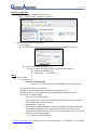
Productivity 3000/ C-More Demo Page |2 Ethernet Configuration: Go to: Start –> Settings –> Network Connections or Start –> Control Panel –> Network Connections: Double click on Local Area Connection Click Properties Scroll down until you see “Internet Protocol (TCP/IP)” then double-click on it Click – use the following IP address Click on “Use the following IP address” and enter these settings: IP address: 192.168.1.100 Subnet mask: 255.255.255.0 Demo: OK, Let’s begin - Clear PAC memory o Put switch into STOP mode Click PAC – Remove PAC project – see WARNING – remove PAC project - File, new project, (No use PC project) Fit ladder to size of window using zoom and click on double arrow Now we will make sure our program knows what hardware it is being used with Go to Setup - Hardware Config. o Double click on local base group o Read configuration – this reads the PAC to find out what base is being used and which modules are currently installed. o Base Mismatch – Yes to all Note: With the “Read Configuration” function, the software automatically senses your hardware setup but if you are programming without a PAC next to you, modules can be added from the list to the right…just drag the module into the rack. o Go back to local base group again Double click on P3-550 CPU www.quantumautomation.com | 4400 East La Palma Ave. Anaheim, CA 92807. | P: 714-854-0800. | F: 714-854-0803 Page |3 Click to enable project transfer to/from USB drive Click on Ethernet Tab o Click on Use the following IP Address – “192.168.1.102” Click on the tab labeled “Serial Ports”. Notice the color coding of the ports and the Click OK to exit o o - Now you will assign Tag Names to the hard I/O points that will be used in this demo Double click on 1st input module This is where we can change the tag names of the IO points Let’s change the 1st point, DI-0.1.1.1 to “Start Pump 1” 2nd point to “Stop Pump 1” 3rd point to “Manual Pump 1” 4th point to “Start Pump 2” 5th point to “Start Pump 3” 6th point to “Pump 3 Timer Reset” 9th point to “Data Log Trigger” (Note: this module is Hot Swappable if we enable it) Click OK Double Click module 2 Change D0-0.1.2.1 to “Pump 1” 2nd point to “Pump 2” 3rd point to “Pump 3” Click OK Double Click on module 3 This is where we configure our Analog module Point out the configurability of the module 0-10V or 0-5V o Each point can have a different range (Click Input Range of each tag to change it) o Go to P3-User Manual to differentiate module configurability (Note: P3-08AD can be configured to read current and voltage on the same module and the same for the P3-06DAS also can be configured on a point to point basis). De-select ALL and select the first 2 channels of the module to be updated o Change the tag name AIS32-0.1.3.1 to “Tank Level 1 Raw” o 2nd point to “Tank Level 2 Raw” o Click OK X out of hardware configuration (Note: You do not have to change the default Tag Names if you don’t want to. They will function the same either way. ) Application Tools (Note: read them all to familiarize yourself with the navigating tools) Application Tools – Setup – Set PAC time/date – PC Time – Apply – X out Now we can start programming www.quantumautomation.com | 4400 East La Palma Ave. Anaheim, CA 92807. | P: 714-854-0800. | F: 714-854-0803 Page |4 o o Optional: If you would like to reference the keyboard shortcuts Open “Help” Menu Click on Index Type Keyboard Shortcuts o Note most Direct-soft Hot Keys are available for use in the Productivity 3000 software Return to ladder window Press F2 for NO Contact (normally open) Use the Tag you created called “Start Pump 1.” (Notice: predictive typing searches the Tag Database and displays the closest match to what you are typing even before you finish. This feature saves time and is convenient for programs with many Tags.) Click on column 2 or press right arrow key Press F3 for NC Contact (normally closed) (or could be safety interlocks) Start typing tag name “Sto” – now select “Stop Pump 1” from list shown – then click OK To create space for an OR branch, press ENTER or carriage return Press F2 for NO Contact Start typing the tag name “Man” – now select “Manual Pump 1” from list shown – then click OK Complete OR branch by drawing wires – press and hold CTRL key and arrow right, then arrow right, then arrow up. This should complete the OR branch. (Note: to erase wires, press and hold the CTRL and Shift keys and arrow over wire to be erased. Click on Zoom double arrow once to fit to screen Click on END coil Press F4 for OUT coil o Type “Pum” – then select “Pump 1” from list --- OK Go to Rung# 2 - Now you will program a simple timer F2 for NO contact – “Start Pump 2” ---- OK Drag Simple Timer from Instruction List to End of Rung 2 o Type Preset Value to “500” = 5 seconds o Tab or click to the next field Current Value “Pump 2 Delay Time” o Tab or click to the next field Done “Pump 2 Delay Done” o Click OK o Define Tag Dialog will pop up showing because you have created two new Tags. The pop up displays the New Tag Names, Description, and Data Type– click OK to confirm Click on Rung 3 o F2 for NO contact “Pump 2 Delay Done” o Click on END of rung 3 and press F4 for OUT coil “Pump 2” o Click OK www.quantumautomation.com | 4400 East La Palma Ave. Anaheim, CA 92807. | P: 714-854-0800. | F: 714-854-0803 Page |5 o Now Resize (if necessary) Now we will program a complex timer F2 for NO contact on rung 4 – “Start Pump 3” ---- OK Drag Timer from Instruction List to End of Rung 4 o Type Preset Value to “5000” o Tab or click to Current Value – “Pump 3 Delay Time” o Tab or click to = Preset – “Pump 3 Timer Done” o Click on <Preset – “Pump 3 Timer Enable” ( Note: This is equivalent to an AB T4:5.EN for enable bit of timer) o Click on >Preset – “Pump 3 Timer Done” (Note: This is the same tag name that we used for =Preset because it will give us the status when Timer is > or = to preset) o Change Time Base to msec (ie 5000 msec = 5 sec) o Click OK o Define Tag dialog box opens (confirm tags) --- OK Click on Rung 4.1 o F2 for NO contact – “Off” --- OK o Define Tag opens (confirm tags) --- OK (Note: this tag is a never on dummy – i.e. our timer will only be counting up) Click on Rung 4.2 o F2 for NO contact – “Pump 3 Timer Reset” --- OK o Press ENTER (Note: created space for rung 4.3) o F2 for NO contact – “C-more Pump 3 Timer Reset” --- OK o Press and hold CTRL and arrow right to draw wire, arrow up to complete OR branch Click on Rung 5 o F2 for NO contact – “Pump 3 Timer Done” --- OK o Click on END – F4 for OUT coil – “Pump 3” --- OK Now you will convert the 0-10V analog input signals to engineering units. In this case a 0-100 scale will be used to simulate the percentage of volume used in two tanks. In the Instruction List find “Application Functions” - Drag Scale (Linear) to end of Rung 6 o Input “Tank Level 1 Raw” o Output “Tank Level 1” o In Min “0” o In Max “65535” (this is the largest 16-bit binary number which is equivalent to 10V for the P3-8AD4DA-2 module) o Out Min “0” o Out Max “100” o Click OK o Define Tags dialog --- OK Highlight the “SCALE LINEAR” block at the end of Rung 6 o Use Ctrl+C to copy it www.quantumautomation.com | 4400 East La Palma Ave. Anaheim, CA 92807. | P: 714-854-0800. | F: 714-854-0803 Page |6 o o Use right click or ctrl+v to paste it to the end of Rung 7 Double click the pasted box and change only the following: Input “Tank Level 2 Raw” Output “Tank Level 2” o Click OK o Define Tags dialog --- OK Save Program o File – Save Project – Tank Pump Application – Save Transfer to PAC o File – Transfer Project – To PAC Run the application o Flip switch on PAC to RUN mode o Click Monitor Mode in the Gray portion of Ladder window Move switch 1 to on position – turns on pump 1 Move switch 2 to on position – turns pump 1 off Move switch 3 to on position – turns pump 1 on Move switch 4 to on position – starts pump 2 delay timer Move switch 5 to on position – starts pump 3 delay timer Move switch 6 to on position – resets pump 3 delay timer o In the “Application Tools” pane open “Data View” Click Add Tags o (Note: for those familiar with C-more, this is the same look and feel – instructions to the right – navigation to the left) Add the following Tags by clicking the empty space in the Tagname column and Typing the name. (note predictive typing can be used here too) “Start Pump 1” “Start Pump 2” “Start Pump 3” “Pump 1” “Pump 2” “Pump 3” “Pump 2 Delay Time” “Pump 3 Delay Time” “Tank Level 1 Raw” “Tank Level 1” “Tank Level 2 Raw” “Tank Level 2” Observe status by switching the simulator input module Observe analog values by turning potentiometers (note: raw vs engineering units) - USB functionality (Note: Sandisk pen drives are the only ones approved/tested by ADC) www.quantumautomation.com | 4400 East La Palma Ave. Anaheim, CA 92807. | P: 714-854-0800. | F: 714-854-0803 Page |7 o Put Pen Drive into “USB OUT” port Application Tools – Monitor & Debug – Data Logger – double click Click Event Data Logging Type a tag into Event Bit Tag Name – “Data Log Trigger” USB Device File Name – “Customer first name” Tag names to Log – “Tank Level 1” “Tank Level 2” “Start Pump 1” “Start Pump 2” “Start Pump 3” Apply – X out o o o o o - - - - File - Save – Project File – Transfer Project – To PAC Stop Mode Transfer (Note: when modifying ladder, runtime edits are allowed) (This download actually modified CPU configuration which requires a Stop Mode Transfer) Now to log some data. The “Data Logger” triggers on the rising edge (off-on) of a Boolean tag, in your case “Data Log Trigger”. It can also occur at regularly scheduled intervals. o Change value (off to on) in switch 1 – then flip switch 9 on then off o Change value (on to off) in switch 1 – then flip switch 9 on then off o Change value (off to on) in switch 2 – then flip switch 9 on then off o Change value (on to off) in switch 2 – then flip switch 9 on then off o Change potentiometer 1 – then flip switch 9 on then off o Change potentiometer 2 – then flip switch 9 on then off o Etc On the physical P3-550 CPU, press the menu button, down arrow to M8USB DRV, then press ENT button to access the USB drive options. o Put CPU switch in STOP position o Press ENT to select SAVE->PEN to save program to USB stick (note: this function only works when CPU switch is in STOP position o The LED should say PASSWORD:0000 Press ENT when ready Arrow down to Remove Press ENT Message should read “REMOVE PEN DRIVE NOW” Take USB stick and put it in PC USB port o You should have a LOGS directory and a P3-550 directory LOGS should read customer name and date and time Double click on the file and it will be in EXCEL - P3-550 is the saved project for your backup records C-more programming o Open C-more software (must be V2.53 or greater – see Help – About) File – Start Project Make New Project – Type Project Name “Tank Pump Application” www.quantumautomation.com | 4400 East La Palma Ave. Anaheim, CA 92807. | P: 714-854-0800. | F: 714-854-0803 Page |8 Specify HMI type – EA7-XXX --- OK Function – Double click panel manager Click on DEV001 o Change PLC protocol Automation Direct Productivity 3000 Ethernet All tags associated with this device mode will be set as Internal. Do you want to proceed? --- Yes o Type IP address “192.168.1.102” --- OK Click to highlight Panel EA7-XXX o Go to bottom right field called BEEP Click OFF --- OK File – Import – Tag Name Database – Click Browse button – find your P3000 Tank Pump application – Click on it – Click on open – then click Import Import Complete --- OK From Object Library Drag indicator light to display o Change Name text, Off Text, & On Text, to “Pump 1” o Change Tag Name to “Pump 1” o Leave as default colors o Click on object and drag to desired spot on screen (change size to 5 vertical by 7 horizontal) o Control C, then Control V to make 3 identical objects o Double click on 2nd and 3rd objects and change text and tag name to “Pump 2” and “Pump 3” respectively Drag Numeric Display to your page o Tag Name to “Pump 2 Delay Time” o Change fractional digits to “2” o OK o Move and size just left of “Pump 2” o Control C, then Control V to make duplicate object and place left of “Pump 3” o Double click and change tag name to “Pump 3 Delay Time” o Change Fractional Digits “3” (Note: msec timer) o OK Drag Pushbutton to page o Change Name text, Off Text, & On Text to “Pump 3 Timer Reset” o Change tag name to “C-more Pump 3 Timer Reset” o Object type – click Momentary On o OK o Size and position below Pump 3 Drag Bar Meter to page o Tag name – “Tank Level 1” o Click on label – “Tank 1” o Click on Show Digital Display --- OK o Position it left of all the Pump Indicator Lights www.quantumautomation.com | 4400 East La Palma Ave. Anaheim, CA 92807. | P: 714-854-0800. | F: 714-854-0803 Page |9 o o o o o - Size to 8 wide by 22 (top of Pump 1 to bottom of Pump 3 Timer Reset) Control C, Control V and move to left of 1st one Tag name – “Tank Level 2” Click on label – “Tank 2” --- OK Move everything to the top left of the page – see below o File – Save Project Your screen should look like this: Send Project to Panel o Transfer type – Ethernet – then Browse o Click to highlight auto discovered C-more panel o Click on the Change IP Address at the bottom left In the Change IP Address window Change Panel Name to “Tank_Pump_Application” Click on Use the following IP Address o “192.168.1.101” Click on Subnet Mask field o “255.255.255.0” OK Click to highlight C-more panel OK Click Transfer Button on Step 3 Project Transfer Page Adjust to Original Resolution (if necessary) --- OK www.quantumautomation.com | 4400 East La Palma Ave. Anaheim, CA 92807. | P: 714-854-0800. | F: 714-854-0803 P a g e | 10 - Time to have fun and use the switches on your simulator input module and make sure everything works. o Don’t forget about the LED on the Analog Module Press and hold SEL button until the desired display title is shown Display units – Volts and release o By turning the Potentiometer you should see the voltage changing on the analog module LED from 0 – 10V. Display units – Decimal and release o By turning the Potentiometer you should see the Decimal change from 0 – 65535 depicting 16-bit resolution. Thank you for your time. You are now ready to program the Automation Direct Productivity 3000 Programmable Automation Controller, the C-more Human Machine Interface, use the Pen Drive to Data Log to a .CSV file, and import to PC directly opening up an Excel Spreadsheet. Congratulations!!! - Now it’s time to talk about your application. www.quantumautomation.com | 4400 East La Palma Ave. Anaheim, CA 92807. | P: 714-854-0800. | F: 714-854-0803