1
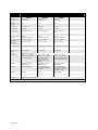
HS-5100, HS-5200, HS-5400 ANALOGUE ADDRESSABLE CONTROL PANELS Remote Terminal Manual Approved Document UI-ELAN-03 Revision 02 Item Specification Details HS-5010 HS-5020 HS-5030 Enclosure Steel IP30 Steel IP30 Steel IP30 Dimensions H x W x D mm 218 x 300 x 42 218 x 300 x 42 263 x 300 x 42 Weight (excluding batteries) 2.1Kg 2.1Kg 2.5Kg Temperature -5°C to 40°C -5°C to 40°C -5°to 40°C Humidity (RH) 95 % Max 95 % Max 95 % Max Cable Entries (20mm knockouts) 4x top / 4x bottom rear 4x top / 4x bottom rear 4x top / 4x bottom rear / 2 bottom DC Power Supply Voltage 24 VDC, Operating range 15-30V 24 VDC, Operating range 15-30V 24 VDC, Operating range 15-30V DC Supply Current (Maximum) DC Supply Current (Quiescent – backlight dimmed) 115mA (/FT: 150mA) 115mA (/FT: 150mA) 115mA (/FT: 150mA) 70mA (/FT: 105mA) 70mA (/FT: 105mA) 70mA (/FT: 105mA) Supply Monitoring Monitored External Fault Input Monitored External Fault Input Monitored External Fault Input Number of Fire Zones 2000 ‘Dynamix’ 2000 ‘Dynamix’ 2000 ‘Dynamix’ Display Backlit 240 x 64 graphical LCD LED Indicators 2 Red (1 x Fire, 1 x More Alarms), 1 Green (Power) & 3 Yellow (Fault & Status) 2 Red (1 x Fire, 1 x More Alarms), 1 Green (Power) & 3 Yellow (Fault & Status) – Optional 1 bi-colour Red/Yellow and 3 Yellow (Status) 2 Red (1 x Fire, 1 x More Alarms), 1 Green (Power), 6 bi-colour Red/Yellow (Status) & 18 Yellow (Fault & Status) Keypad Alpha Numeric Keypad, Navigation Keys Alpha Numeric Keypad, Navigation Keys Alpha Numeric Keypad, Navigation Keys Controls System Key for Mute System Keys for Mute, Silence, Reset & Resound & More Alarms System Keys for Mute, Silence, Reset & Resound & More Alarms – 6 Optional Programmable keys Serial port USB only USB only USB and RS232 Event Log 1000 Event & Diagnostic + 500 Fire As our policy is one of constant product improvement the right is therefore reserved to modify product specifications without prior notice Page 2 of 36 Table of Contents 1 Page INTRODUCTION ___________________________________________________________ 5 1.1 Standards _____________________________________________________________ 1.2 Cautions and Warnings __________________________________________________ 1.3 Description ____________________________________________________________ 1.3.1 HS-5000 Series _____________________________________________________ 1.4 EN54 Functions ________________________________________________________ 1.4.1 EN54 Optional Features with Requirements ______________________________ 1.5 Installation Approvals ____________________________________________________ 1.5.1 Fire System Installations ______________________________________________ 1.5.2 Wiring Regulations __________________________________________________ 2 5 6 6 6 7 7 8 8 8 OPERATION ______________________________________________________________ 9 2.1.1 HS-5010 __________________________________________________________ 9 2.1.2 HS-5020 __________________________________________________________ 9 2.1.3 HS-5030 __________________________________________________________ 9 2.2 Controls and Indications_________________________________________________ 10 2.2.1 Graphical Display __________________________________________________ 10 2.2.2 LED Status Indicators _______________________________________________ 11 2.2.3 Control Buttons ____________________________________________________ 12 2.2.4 Navigation Buttons _________________________________________________ 12 2.2.5 Number and Letter Buttons ___________________________________________ 13 2.2.6 Buzzer ___________________________________________________________ 13 2.3 Access Levels ________________________________________________________ 13 2.3.1 Changing from Access Level 1 to Level 2 _______________________________ 14 2.3.1.1 2.3.1.2 Menu Access ___________________________________________________________ 14 Control Buttons at Level 1 _________________________________________________ 14 2.3.2 Changing from Access Level 2 to 1 ____________________________________ 2.4 User Menu Functions ___________________________________________________ 2.4.1 View ____________________________________________________________ 2.4.2 Disable __________________________________________________________ 2.4.3 Enable ___________________________________________________________ 2.4.4 Test _____________________________________________________________ 2.4.5 Print _____________________________________________________________ 3 INSTALLATION __________________________________________________________ 17 3.1 Identification of Parts ___________________________________________________ 3.1.1 HS-5010 / HS-5020_________________________________________________ 3.1.2 HS-5030 _________________________________________________________ 3.2 Installing the Enclosure _________________________________________________ 3.2.1 Opening the Enclosure Cover _________________________________________ 3.2.2 Removing the Chassis ______________________________________________ 3.2.3 Mounting the Enclosure _____________________________________________ 3.2.4 Remounting the Chassis _____________________________________________ 3.2.5 Recommended Cable Routing Arrangement _____________________________ 3.3 Wiring Installation ______________________________________________________ 3.3.1 DC Power Installation _______________________________________________ 3.3.2 Network Interface __________________________________________________ 3.3.3 Switch Inputs ______________________________________________________ 3.3.4 RS232 Interface ___________________________________________________ 3.3.5 USB Interface _____________________________________________________ 4 14 15 15 15 15 16 16 17 17 17 18 18 18 18 19 19 20 20 21 21 22 22 PROGRAMMING _________________________________________________________ 23 4.1 Introduction___________________________________________________________ 4.1.1 Access Levels _____________________________________________________ 4.1.2 Memory Lock _____________________________________________________ 4.1.3 Navigating through menus ___________________________________________ 4.1.4 Changing Text Descriptions __________________________________________ 4.1.5 Numeric data entry _________________________________________________ 4.2 Level 3 Menu Functions _________________________________________________ 23 23 23 23 24 25 25 Page 3 of 36 4.2.1 4.2.1.1 4.2.1.2 PC ONLY Functions ________________________________________________ 25 Fire Protection Indications _________________________________________________ 25 Beacons _______________________________________________________________ 25 4.3 Recommended Programming Procedure ____________________________________ 26 4.3.1 Zones ____________________________________________________________ 26 4.3.2 Exit ______________________________________________________________ 26 4.3.3 View Options ______________________________________________________ 26 4.3.4 Passwords ________________________________________________________ 27 4.3.5 Time and Date _____________________________________________________ 27 4.3.6 PC Config ________________________________________________________ 27 4.3.7 Setup ____________________________________________________________ 28 4.3.7.1 4.3.7.2 4.3.7.3 4.3.7.4 4.3.7.5 4.3.7.6 4.3.7.7 5 Network _______________________________________________________________ 28 Panel Zone _____________________________________________________________ 28 Service Number _________________________________________________________ 28 Service Due Date ________________________________________________________ 28 Trace Logging Mode _____________________________________________________ 28 Resound _______________________________________________________________ 29 Config Data ____________________________________________________________ 29 SERVICE AND MAINTENANCE ______________________________________________ 30 5.1 Maintenance Schedule __________________________________________________ 30 5.1.1 Daily Actions ______________________________________________________ 30 5.1.2 Monthly Actions ____________________________________________________ 30 5.1.3 Quarterly Actions ___________________________________________________ 30 5.1.4 Annual Actions_____________________________________________________ 30 5.2 Replacement of Components _____________________________________________ 31 5.2.1 Liquid Crystal Display _______________________________________________ 31 5.2.2 Spares ___________________________________________________________ 31 6 APPENDICES ____________________________________________________________ 32 6.1 Appendix 1 – Forgotten Level 3 Password ___________________________________ 32 6.2 Appendix 2 – Recommended Fire Rated Cables ______________________________ 33 6.2.1 Network Cables ____________________________________________________ 33 Page 4 of 36 1 Introduction 1.1 Standards Advanced Electronics Ltd declares that the products identified below conform to the essential requirements specified in the Construction Products Directive 89/106/EEC: 0786-CPD-20952 EN54-2: 1997 +A1:2006 Control and indicating equipment for fire detection and fire alarm systems for buildings Provided options: Outputs to Fire Alarm Devices Output to Fire Routing Equipment Output to Fire Protection Equipment Output to Fault Routing Equipment Investigation Delays to Outputs Dependency on more than one alarm signal Fault Signals from Points Disablement of Points Alarm Counter Test Condition Standardised Input / Output HS-5030, HS-5030-FT, In addition, the products comply with the following: Low Voltage Directive 2006/95/EC BS EN60950-1: 2006 Safety of information technology equipment Electromagnetic Compatibility Directive 2004/108/EC BS EN55022: 1998 Emissions, Class B BS EN50130-4: 1996 +A2: 2003 Immunity, Product Family Standard Page 5 of 36 1.2 Cautions and Warnings BEFORE INSTALLATION – Refer To the Ratings shown on the label inside the product and to the ‘Specifications Chart’ in this document. Please read this manual carefully. If you are unclear on any point DO NOT proceed. Contact the manufacturer or supplier for clarification and guidance. STOP Only Trained service personnel should undertake the Installation, Programming and Maintenance of this equipment. This product has been designed to comply with the requirements of the Low Voltage Safety and the EMC Directives. Failure to follow the installation instructions may compromise its adherence to these standards. ATTENTION OBSERVE PRECAUTIONS FOR HANDLING ELECTROSTATIC SENSITIVE DEVICES PC ONLY 1.3 This equipment is constructed with static sensitive components. Observe antistatic precautions at all times when handling printed circuit boards. Wear an anti-static earth strap connected to panel enclosure earth point. Before installing or removing any printed circuit boards remove all sources of power (mains and battery). Where you see the “PC Only” symbol, these features can either only be set-up using the PC Configuration Tool or there are additional options that are only available via the PC Configuration Tool. Description This manual covers the installation, programming and operation of the Mx-5000 Series Remote Control Terminal Panels. This manual provides generic programming and installation information. Refer to the User Manual (Document No. 680-166) for additional details of how to operate the fire alarm control panel. 1.3.1 HS-5000 Series The HS-5020 is a basic Remote Control Terminal. The HS-5030 is a full function Remote Control Terminal. Install the panel in accordance with the instructions in Section 3 and then program the operation in accordance with the instructions detailed in Section 4. The basic operation is indicated in Section 2 and is fully detailed in User Manual UI-ELAN02 which is common to all of the HS-5000 control panels. Page 6 of 36 1.4 EN54 Functions The Remote Terminal Panels in conjunction with the HS-5000 Control Panels are compliant with the requirements of EN54-2 (1997) and EN54-13 (2005). In addition to the basic requirements, the following optional functions are provided and these comply with the requirements of EN54. C.I.E Optional Functions Indication Outputs Controls Outputs to Fire Alarm Devices Outputs to Fire Routing Equipment Investigation Delays to Outputs Co-incidence Detection Alarm Counter Fault Signals from Points Output to Fault Routing Equipment Disablement of Points Test Condition Standardised I/O EN54-2 Clause 7.8 7.9 7.11 7.12 Type B & Type C 7.13 8.3 8.9 9.5 10 11 1.4.1 EN54 Optional Features with Requirements In addition to the mandatory requirements of EN54 Part 2, the Remote Terminal Control and Indicating Equipment (C.I.E) supports the indication and control of the following optional features with requirements: Outputs to Fire Alarm Devices. Section 7.8 The Remote Terminal C.I.E has provision for the indication of conditions relating to fire alarm device outputs. It is possible to Silence and Re-sound the alarms at Level 2. Outputs to Fire Routing Equipment. Section 7.9 The Remote Terminal C.I.E has provision for the indication of conditions relating to the transmission of the fire alarm condition to a remote receiving station such as the fire brigade office. Outputs to Fire Protection Equipment. Section 7.10 The Remote Terminal C.I.E has provision for the indication of conditions relating to the transmission of the fire alarm condition to fire protection equipment. Delays to Outputs. Section 7.11 The Remote Terminal C.I.E has provision for the indication of conditions relating to Output and Investigation Delays. Page 7 of 36 Coincidence Detection. Section 7.12 The Remote Terminal C.I.E has provision for the indication of Coincidence Detection. Types B and C are supported in the HS-5000 Series control panels. Alarm Counter. Section 7.13 The Remote Terminal C.I.E has provision to record the number of times that the fire alarm condition is entered. Fault Signals from Points. Section 8.3 The Remote Terminal C.I.E has provision for the indication of conditions relating to fault signals from points. These are indicated on a per zone basis. Outputs to Fault Routing Equipment. Section 8.9 The Remote Terminal C.I.E has provision for the indication of the conditions relating to the transmission of the fault condition to a remote receiving station such as the service centre office. Disablement of Points. Section 9.5 The Remote Terminal C.I.E has provision for enabling and disabling signals from points over the Ad-Net Network. Test Condition. Section 10 The Remote Terminal C.I.E has provision for enabling the testing of the installation on a per zone basis over the Ad-Net Network. Standardised Input/Output interface. Section 11 1.5 The Remote Terminal C.I.E provides the Standardised I/O interface for the indication and control of the mandatory conditions over the Ad-Net Network. Installation Approvals 1.5.1 Fire System Installations The panel must be installed and configured for operation in accordance with these instructions and the applicable code of practice or national standard regulations for fire systems installation (for example BS5839-1: 2002) appropriate to the country and location of the installation. 1.5.2 Wiring Regulations The panel and system must be installed in accordance with these instructions and the applicable wiring codes and regulations (for example BS7671) appropriate to the country and location of the installation. Page 8 of 36 2 Operation The operation of the remote terminals and the available controls and indications are identical to those of the HS-5000 Series Control Panels. For full details, refer to the User Manual UI-ELAN02. The following information identifies the buttons and indications available on each variant of the remote terminals. The fascia layouts for the standard UK Remote Terminals Panels are as follows: 2.1.1 HS-5010 2.1.2 HS-5020 2.1.3 HS-5030 Slide-in labels are used to annotate Function Indicators and Programmable Control Keys and Indicators. Page 9 of 36 2.2 Controls and Indications 2.2.1 Graphical Display The graphical display provides detailed information of the source of fire alarms, faults and warnings. It also shows menus for use when inspecting or programming the operation of the panel. Under normal conditions the panel display shows the access level, time, date and status: - HS-5000 LEVEL 2 16:05 04 MAR 2008 NORMAL PANEL OPERATION (Press Menu to View) For full details, refer to the User Manual UI-ELAN-02. Page 10 of 36 2.2.2 LED Status Indicators The LED Status Indications show the basic operational state of the panel and whether the panel is in a fire alarm, fault, disabled or test condition. Function 5010 5020 5030 Colour Description FIRE 4 4 4 Red Indicates that the system has detected a fire alarm condition MORE ALARMS 4 4 4 Red Indicates that the system has detected a fire alarm condition (on steady) in more than one zone. Fault 4 4 4 Yellow Indicates that the system has detected a fault condition Disable 4 4 4 Yellow Indicates that part of the system has been disabled (i.e. isolated) Test 4 4 4 Yellow Indicates that part of the system is in a test condition Power 4 4 4 Green Indicates the presence of power Fire Routing Activated 5 5 4 Red Indicates that the output to call the Fire Brigade has been Activated Fire Routing Fault 5 5 4 Yellow Indicates that there is a fault condition in the Fire Brigade signalling equipment. Fire Routing Disabled 5 5 4 Yellow Indicates that the output signal to the Fire Brigade is Disabled Pre-Alarm 5 5 4 Yellow Indicates that a smoke or heat detector has detected a change in the environment that may develop into a possible fire alarm condition. Delayed 5 5 4 Yellow Indicates that one or more output circuits are in a delayed operating condition Fire Protection Activated 5 5 4 Red Indicates that the circuit to fire extinguishing or other fire protection equipment has been activated or that the fire protection equipment itself has been activated. Sounder Silenced 5 5 4 Yellow Indicates that the sounders have been silenced Sounder Fault 5 5 4 Yellow Indicates the presence of a fault in one or more sounder wiring circuits Sounder Disabled 5 5 4 Yellow Indicates that one or more sounders have been disabled (i.e. isolated) System Fault 5 5 4 Yellow Indicates the presence of a system fault Function 1 5 OPT 4 Red/Yel Spare function LED Function 2 5 OPT 4 Yellow Spare function LED Function 3 5 OPT 4 Yellow Spare function LED Function 4 5 OPT 4 Yellow Spare function LED Function 5 5 5 4 Yellow Spare function LED The function LED Indicators are programmable and can be configured and labelled accordingly during installation and commissioning of the system. The arrangement and definition of the Status LED Indicators depend on the country and market requirements. The functions described are the same and the most common layout is shown. Page 11 of 36 2.2.3 Control Buttons The following table contains a list of all of the control button functions available. The buttons available on each product depend on the country of installation and specific market requirements. Button ! Description Access Level More Alarms Press to scroll through Zones in Alarm. The LED indicator turns on to indicate if more than one zone is in alarm. Available in both Level 1 and Level 2 Reset Press to reset the panel from a fire alarm or latched fault condition. Only available with Level 2 Access. Mute Press to mute the internal buzzer. Available in both Level 1 and Level 2 Silence Only available with Level 2 Access. Press to silence the sounders. Resound Press to re-activate the sounders. Only available with Level 2 Access. Evacuate Press to initiate a manual evacuation and sound the alarms. Only available with Level 2 Access. LED Test Press to illuminate ALL LED indicators Available in both Level 1 and Level 2 Disable Press to disable the zone or device in a fire alarm condition (Australia only). Only available with Level 2 Access. Function Button Programmable function – an associated LED indicator can also be programmed Depends on Programming 2.2.4 Navigation Buttons Press to scroll through Menu Options. Press to display more information. Press to scroll through lists of zones or devices. Page 12 of 36 Press to confirm entry of numeric or letter information entry. Press to confirm selection of a menu option. Press to change some of the configuration options. 2.2.5 Number and Letter Buttons GHI ABC D EF JKL MN O Used to enter numbers or letters. PQRS TUV ESC WXYZ MENU Esc Press to return to a previous menu. Press to exit the menu functions and return to the normal display. Menu Press to show or return to Menu Functions. 2.2.6 Buzzer The buzzer produces two different sounds to differentiate between fire alarm conditions and fault conditions. Condition Operation Fire Alarm The buzzer operates with a continuous tone. Fault The buzzer operates intermittently. 2.3 Access Levels The panel operation is protected from inadvertent and erroneous misuse by means of four access levels. These levels are as follows: Level 1 Level 2 Level 3 Level 4 Untrained user Authorised User Service and Maintenance Engineer Service and Maintenance Engineer – Special Tools required A Level 1 Untrained User can view the current operational condition of the system and may MUTE the internal buzzer. NOTE: Depending on the configuration settings, a Level 1 user may also be permitted to EVACUATE and/or SILENCE and/or RESET the system by pressing the appropriate button and entering a password. A Level 2 Authorised User can view the operational condition of the system and may MUTE the internal buzzer. In addition, the SILENCE, RESOUND and RESET buttons are enabled and access to the Level 2 Menu functions is available. EVACUATE is also possible on the HS-5030. NOTE: There are up to 10 User ID codes available, each with its own password, which can be configured with varying permissions to specific menu function options. A Level 3 User has access to program and configure the operation of the panel. This is described in detail in Section 4. Page 13 of 36 2.3.1 Changing from Access Level 1 to Level 2 If the panel has an access key switch fitted, use the key in preference to the menu options shown below. 2.3.1.1 Menu Access Press the ‘MENU’ button. The level 1 menu will be displayed as shown below: [ CONTROLS DISABLED ] ENABLE CONTROLS LED-TEST VIEW STATUS To enable the controls, ensure the “Enable Controls” option is highlighted and then press the 4 button. The display then requests entry of the Level 2 or 3 passwords as follows: [ CONTROLS DISABLED ] Please Enter Your Password Enter the password using the number buttons and then press the 4 button. As each number is entered, an asterisk (*) is shown on the display. For example: [ CONTROLS DISABLED ] Please Enter Your Password ** If the password is correct, the Level 2 Menu options will be shown. If the password is incorrect, the display briefly shows the following message. [ CONTROLS DISABLED ] Please Enter Your Password Password Not Recognised ! 2.3.1.2 Control Buttons at Level 1 If any of the control buttons (Reset, Silence / Resound or Evacuate) are pressed, the display automatically prompts for the password. Enter the password as above. 2.3.2 Changing from Access Level 2 to 1 If the panel has an access key switch fitted, use the key switch. Alternatively, if passwords are used, select the “Disablement” menu and then select “Disable/Controls” – refer to HS-5000 User Manual for full details. Page 14 of 36 2.4 User Menu Functions When Level 2 is enabled, the following User Menu is shown. [Commission Menu 1] VIEW TEST DISABLE PRINT ENABLE COMMISSION When a menu is displayed, use the buttons to highlight the required menu option and then press the 4 button to select it. Press the ‘Esc’ button from within a menu option to return to the previous menu. The display can be forced back into status mode by pressing the ‘Esc’ button when at the top level commissioning menu (or by waiting 60s). 2.4.1 View Refer to the HS-5000 User Manual for further information. The following options can be viewed: Fire Alarms Fault Conditions Other Alarm Conditions Disablement Conditions Inputs Outputs Network Software Versions 2.4.2 Disable Refer to the HS-5000 User Manual for further information. The following options can be disabled: Zones / Inputs Outputs Delay Mode Groups 2.4.3 Enable Refer to the HS-5000 User Manual for further information. The following options can be disabled: Zones / Inputs Outputs Delay Mode Groups Page 15 of 36 2.4.4 Test Refer to the HS-5000 User Manual for further information. The following functions can be tested: Zones / Inputs Display Buzzer Printer (if available – Mx-5030 only) 2.4.5 Print The HS-5030 can support an external printer connected via the RS232 I/F. Refer to the HS-5000 User Manual for further information. Page 16 of 36 3 Installation 3.1 Identification of Parts The following diagrams show the major parts of the panels. 3.1.1 HS-5010 / HS-5020 The HS-5010 and HS-5020 comprise of a back box, chassis plate electronic assembly and a cover. Back Box The chassis plate is fixed to the back box with two screws. The cover is fixed to the back box with two hex (Allen) key screws. The cover earth lead must be connected to the spade terminal in the back box. Chassis Earth Point Cover Earth Lead 3.1.2 HS-5030 The HS-5030 comprises of a back box, chassis plate electronic assembly and a cover. Back Box The chassis plate is fixed to the back box with two screws. The cover is fixed to the back box with two hex (Allen) key screws. The cover earth lead must be connected to the spade terminal in the back box. Chassis Earth Point Cover Earth Lead Page 17 of 36 3.2 Installing the Enclosure Use the appropriate fixing hardware to secure the panel to the wall. See table below for maximum weights. Enclosure HS-5010 Weight 2.1kg Maximum Battery N/A Overall Maximum Weight 2.1kg HS-5020 2.1kg N/A 2.1kg HS-5030 2.5kg N/A 2.5kg 3.2.1 Opening the Enclosure Cover The enclosure covers are fixed with two screws – use the supplied Allen key. Detach the earth lead from the back box to completely remove. Place the cover in a safe place to prevent accidental damage and retain the fixing screws. 3.2.2 Removing the Chassis It is recommended that the chassis be removed before fitting the panel to the wall. To remove the chassis: Disconnect the earth cable connecting the chassis to the spade terminal on the rear enclosure. Remove the two screws holding the chassis to the back box and carefully remove the chassis from the rear enclosure. Place the chassis in a safe place to prevent accidental damage and retain the fixing screws. Do not lift the chassis by holding onto any of the printed circuit cards. Hold the chassis by the metal plate only. 3.2.3 Mounting the Enclosure Firstly, remove the required knockouts for the installation wiring. There are sufficient knockouts on the top of the enclosure for all installation wiring. In addition, there are knockouts at the bottom of the back wall, if required, for rear entry cabling. The enclosure is provided with three fixing points. 296 Ensure that there is sufficient space to allow the door to be opened when the panel is mounted. Finally, use a brush to remove any dust or swarf from inside the enclosure. Page 18 of 36 174 23 Drill the required holes in the supporting wall using a drill bit diameter 7.0 mm and plug with a suitable 40mm or longer expansion plugs. Affix the panel to the wall with M5 screws or No.10 screws. Use appropriate fixings to support the weight including the batteries. 213 The diagrams opposite and below show the positions of the three holes and dimensions of each enclosure. Use all three positions to ensure the panel is held securely to the wall. 113 113 HS-5010/HS-5020 Enclosure Size and Fixing Point Dimensions 23 219 258 296 113 113 HS-5030 Enclosure Size and Fixing Point Dimensions 3.2.4 Remounting the Chassis Carefully replace the chassis and fix into place using the two screws. Reconnect the chassis earth cable to the spade terminal in the rear of the enclosure. 3.2.5 Recommended Cable Routing Arrangement It is recommended that the typical routing arrangement shown in the diagram opposite be employed. Power NET In NET Out Segregate the low voltage wiring (DC Power and Network Wiring) from any AC Mains Wiring. Refer to Appendix 2 – Recommended Fire Rated Cables for further information on cable types to be used. Tie-wrap the cables to the back of the enclosure using the anchor points provided. Internal arrangement showing recommended routing of cables. Page 19 of 36 3.3 Wiring Installation All electrical wiring installation work should be carried out in accordance with the code of practice or applicable national standards appropriate to the country of installation. To maintain electrical integrity of the SELV wiring on the DC Power and communications lines all SELV wiring should be segregated from the LV mains wiring and be wired using cable with insulation suitable for the application. To minimise the effects of EMC interference all data wiring circuits should be wired with a twisted pair of conductors with a cross sectional area suitable for the loading conditions. In areas where cabling may come into contact with high frequency interference, such as portable radio transceivers etc. the data wiring cable should be of a twisted pair construction within an overall screen. Care should be taken to correctly terminate this screen, refer to the appropriate sections of this manual for further information for each circuit type. Minimum / Maximum cable size for all external connections is limited to 0.5mm² / 2.5mm² (22-14AWG). 3.3.1 DC Power Installation +24V 0V E 0V +24V The main electronics requires a 24V DC supply – this must be a Safety Extra Low Voltage (SELV) supply provided by an EN54-4 certified PSE. +24V 0V E 0V +24V COM FLT COM NB: The connectors are symmetrical and reversible. The power supply can be distributed to the next unit if required. FEED 1 FEED 1 OUT To Next Unit +24V 0V E 0V +24V Either one (default) or two feeds can be used. EN54-4 Clause 6.4 requires that two separate feeds when the PSE is housed in a separate cabinet. The feeds should be run in separate cables for integrity. Each feed can be monitored and a fault is registered on the loss of any one feed. Monitoring of the second feed can be turned on / off (programming). A common separate PSE fault input can also be connected to the panel to indicate other PSE failures such as charger failure, battery missing, etc. This should be arranged for fail-safe operation with the contacts closed under no fault conditions. If not used, short the FLT and COM terminals with the link provided. Page 20 of 36 +24V 0V E 0V +24V COM FLT COM Must be earthed The enclosure must be connected to the supply earth through the power cable. FEED 1 FEED 2 FEED 1 OUT FEED 2 OUT To Next Unit To Next Unit 3.3.2 Network Interface The network permits the connection of other panels, remote terminals and other devices to complete a distributed system. The Remote Terminal is available as either a (STD) standard network interface peripheral or as an (FT) fault tolerant network interface peripheral. All network nodes must be installed with the same type of interface. Each card has independent connectors for the outgoing and incoming network cable. Using a twisted-pair cable, connect from the “OUT” socket on the first panel to the “IN” socket on the next panel as follows. Cable must be twisted pair 18AWG or 20AWG. OUT Screen B A Screen B A A IN STD (Up to 32 nodes) The “IN” terminals on the first node and the “OUT” terminals on the last node are not used. Connect an ELR (150Ω) resistor between A and B on the terminal blocks of the unused sockets. STD ELR 150ohm ½ W IN O UT ELR 150ohm ½ W IN O UT Maximum cable length (overall length) is 1500m using recommended cables. FT (Up to 200 nodes) Other Network devices must be fitted with a FT type adaptor card. Install a cable from the last node “OUT” terminals back to the first node “IN” terminals to form a ring. Maximum cable length between nodes is 1500m using recommended cables. Maximum cable length (overall length) is 20000m using recommended cables. 3.3.3 B SCN A Do not connect cable screen to earth. B SCN Screened type cable is recommended (e.g. Belden 8760, 8762). Connect the screen to the designated terminal block positions only. IN OUT IN OUT 1500m FT 1500m IN O UT IN O UT IN OUT IN OUT 20000m (m ax) Switch Inputs One key-switch input is provided as standard. An aperture is provided in the cover to mount the key-switch. The function is programmable but typically used for “Access Enable”. Page 21 of 36 The terminal block connections are shown opposite. RX TX RS232 Interface The HS-5030 is equipped with an isolated RS232 I/F Circuit at the bottom of the base card. GND 3.3.4 RS232 TX = Transmit Data from the panel, RX = Receive Data into the panel, GND = Ground Reference. This interface can be used for connection to a modem, PC or external printer. Base Card Connections – typical. 3.3.5 USB Interface The HS-5000 Series Remote Terminals are equipped with an isolated USB I/F Circuit. This can be used for connection to a PC for use of the PC Configuration Tool. The USB Interface uses common signals with the RS232 Interface (if available) – plugging in a USB connection disconnects and isolates the RS232 Interface. Page 22 of 36 4 Programming 4.1 Introduction PC ONLY 4.1.1 These instructions cover the configuration and programming of the panels. Where you see the “PC Only” symbol, these features can either only be set-up using the PC Configuration Tool or there are additional options that are only available via the PC Configuration Tool. Access Levels The panel operation is protected from inadvertent and erroneous misuse by means of four access levels. These levels are as follows: Level 1 Untrained user Level 2 Authorised User Level 3 Commissioning, Service and Maintenance Level 4 Commissioning, Service and Maintenance – Special Tools Required This document covers the Level 3 functions. For details on the operation and use of the panel at Levels 1 & 2, refer to User Manual UI-ELAN-02. Full details are supplied with the special tools. A level-3 password is required to enter the commissioning menus. For details of Passwords, refer to Section 4.3.4. Level-3 Passwords. If this number is lost, it is not possible to enter commission mode functions. Refer to section 6.1 for further formation. 4.1.2 Default 7654 Memory Lock The configuration memory may be protected against inadvertent change by means of a memory lock. Before making any configuration data changes, move the jumper strap to the OPEN position. After all changes have been made, move the jumper strap back to the CLOSE position to protect the memory against inadvertent change. Refer to the diagram opposite for information on the jumper settings. 4.1.3 Typical View – Unlocked Navigating through menus The display will revert to status mode after 60s. Press the ‘Menu’ button to restore the display. [Commission Menu 1] PASSWORDS PC CONFIG ZONES ENABLE EXIT VIEW When a menu is displayed, use the buttons to highlight the required menu option and then press the 4 button to select it. Press the ‘Esc’ button from within a menu option to return to the previous menu. Page 23 of 36 The display can be forced back into status mode by pressing the ‘Esc’ button when at the top level commissioning menu (or by waiting 60s). 4.1.4 Changing Text Descriptions Various parameters can have a text description defined. These include loop devices, zones, etc. The zone and device text descriptions will be shown on the display in the Fire Alarm, Fault and Warning Conditions, etc. to provide a quick and clear indication of the source of the problem. To change the text description, first highlight the text description within the appropriate programming option and then press the 4 button. The display then changes to show the text entry dialogue screen. For example: >RESTAURANT < 1 KEY IN THE REQUIRED TEXT 2abc 3 def 4 ghi 5 jkl 6 mno The method of entering the characters is similar to the method employed on mobile telephones. The number buttons provide both their appropriate number and several letters of the alphabet. An example of the keypad is shown opposite. 7pqrs 8 tuv 9wxyz Esc 0 Menu For example, Button 2 allows entry of the number 2 and letters A, B and C. When a button is pressed, the first character is shown on the display at the current cursor position. If the button is pressed again within ½ second, the second character replaces the first. A further press displays the third available character and so on – see table below. After pressing the button to obtain the required character, wait for 1-second and the character will be entered and the cursor will move to the next character in the text description. Pressing another button will immediately enter the previous character and move the cursor on to the next character. Use the buttons to move backwards or forwards along the line. When the text description is as required, press the 4 button to confirm the change. If the text has been entered incorrectly, press the ‘Esc’ button to cancel all changes and return to the previous display. The following table shows the numbers, characters and symbols assigned to each button on the keypad. st nd 2 Press rd 3 Press th 4 Press th Button 1 Press 5 Press Further Characters 1 1 2 A B C 2 Ä, Æ, Å, À, Á, Â, Ã, Ç 3 D E F 3 È, É, Ê, Ë, Đ 4 G H I 4 Ì, Í, Î, Ï 5 J K L 5 6 M N O 6 7 P Q R S 8 T U V 8 9 W X Y Z 0 Blank 0 Ö, Ø, Ò, Ó, Ô, Õ, Ñ 7 Ù, Ú, Û, Ü 9 Ý, Þ Alternatively, press the buttons to scroll through a list of characters. When the required character is shown, press the button to move on to the next character. The list of characters available and the order of presentation is as follows: Page 24 of 36 Blank !“#$%&‘()*+,-./ 0123456789 :;?@ ABCDEFGHIJKLMNOPQRSTUVWXYZ [‘]^_ 4.1.5 Numeric data entry Numbers are entered by moving to the required field, and then typing in the required number, followed by the 4 button. If the number is entered incorrectly, press the ‘Esc’ button to restore the previous number. 4.2 Level 3 Menu Functions The following table gives a list of the Level 3 Menu Functions, the sub-functions available within each main function and a brief description for each function. The menu options are available on three pages – select “Next Menu” to switch between pages. Main Menu Option Sub Menus Comments 3 ZONES -- Configure the Zone texts. EXIT -- Cancel Level 3 Access and return to Level 2 Menu Options. VIEW Fires View Zones and Inputs that are reporting a fire alarm condition. Faults View Zones and Inputs that are reporting a fault condition. Alarms View Zones and Inputs that are reporting an alarm condition during test. Disabled View Zones, Inputs and Outputs that are disabled. Inputs View the current state of Zones and Inputs. Outputs View the current operational condition of all output circuits. Log View the Event Log. Network View Network Diagnostics. -- Configure the Level 2 and Level 3 passwords. 2 PASSWORDS PC-CONFIG -- Enable the PC Link for transfer of configuration data to and from the panel. 1 SETUP -- Configure General Operating Parameters. 4.2.1 PC ONLY Functions The following features can only be configured using the PC Configuration Tool. Programmable Buttons Programmable LED Indications LCD Back Light Dimming Control Investigation Delays DC Power Feeds – one or two User access permissions The following must also be considered for full compliance and indication in accordance with the requirements of EN54-2 4.2.1.1 Fire Protection Indications If fire protection outputs are configured on the HS-5000 panels, then configure two of the front panel “Function” LED indicators to indicate the fault and the ONLY disabled states of these outputs. PC 4.2.1.2 Beacons PC ONLY If beacon outputs are configured so that they can be independently disabled / enabled, then configure one of the front panel “Function” LED indicators to indicate the disabled state of these devices. Page 25 of 36 4.3 Recommended Programming Procedure The main programming steps required will necessarily be different for each installation. However, the following is the minimum recommended. Step 1 – SET-UP, Define General Set-up Information (Phone Numbers, etc.). Step 2 – PASSWORDS, Define Level 2 and Level 3 Passwords as required. Step 3 – ZONES, Enter Zone Texts as required. 4.3.1 Zones The Commission Zones option lists all the zones in use by this panel and allows the zone text description to be changed. [Commission Zones] Zone Location 0001 BASEMENT WEST 0002 RECEPTION 0015 EAST WING 0018 TOWER BLOCK To change the location text assigned to the Zone, press the 4 button when the Zone Location Text is highlighted. Refer to Section 4.1.4 for guidance on how to change text descriptions. To select a different zone, use either the scroll up/down keys, or just type in the number of the required zone, followed by the 4 button. Note that only zones in use are displayed. 4.3.2 Exit To exit the Commission Mode and return the panel to normal operation (i.e. level 2), select the “Exit” option. The display will prompt for confirmation of the Level 3 password. For example: [Commission Menu 1] Please Enter Your Password Next Menu If the password is incorrect (this will be indicated) or if the password is not entered within 5seconds, the display will revert to the Commission Level Menu and level-2 will not be entered. After commissioning, the panel must always be returned to level 2 (or level 1) to give normal fire coverage. 4.3.3 View Options The View Menu Options are identical to those available during Level-2 operation – refer to User Manual UI-ELAN-02 for further information. Page 26 of 36 4.3.4 Passwords The panel provides up to 10 User Level-2 passwords and 2 Level-3 passwords. All of the passwords 1 can be changed. On entry to the function, the display shows a list of the passwords. For example: Password 15633 9988 13344 10000 10000 Access level 2 2 2 2 2 User ID 01 02 03 04 05 To change a password, use the buttons to highlight the required password and then enter the new password using the number buttons. When the password is correct, press the 4 button to confirm. Level-3 Passwords. Care should be taken when changing the Level-3 password. If this new number is lost, it is not possible to enter commission mode functions. Refer to 6.1 for further information. The factory default level 3 password is 4.3.5 7654 Time and Date This function allows the time and date in the panel to be changed. On entry to the function, the display shows the current time and date with confirmation of the day of the week on the bottom line. For example: [SET TIME/DATE] TIME = 15:28 DATE = 15/01/09 THU 15 JAN 2009 To change the settings, use the buttons to highlight the required option. Directly enter the new time or date using the number buttons. As soon as a number button is pressed, the display will clear the current setting and show the new value as it is entered. For example: [SET TIME/DATE] TIME = 1-:-DATE = 15/01/09 4.3.6 THU 15 JAN 2009 PC Config The PC Link Option enables the connection of the PC Configuration Tool for retrieving configuration data from the panel and programming configuration data from a file on the PC. For further information, refer to the Manual supplied with the PC Configuration Tool. 1 The passwords can be further qualified using the PC CONFIG TOOL to provide permission / restriction to specific menu options. See HS-5000 User Manual and PC CONFIG TOOL Manual for further details. Page 27 of 36 4.3.7 Setup The Setup Options Menu enables the configuration of panel generic operating parameters. When the option is selected, the display shows a list of the available parameters. For example: [Setup] THIS NETWORK NODE NEXT NETWORK NODE PANEL ZONE SERVICE NUMBER : . 0 : 0 : 100 : 01234 567890 . Use the buttons to scroll through the list of options. The following will then be shown: [Setup] SERVICE DUE DATE TRACE LOGGING MODE DETECTOR BLINKING COMPANY LCD LOGO : : : : 01 JAN 2011 STANDARD NONE 4 10:00 More> 4.3.7.1 Network This Network node is set to 0 as default. For panels in a networked application please refer to the Network document. 4.3.7.2 Panel Zone By default all the panel inputs are assigned to the Panel Zone. Alternatively the PC configuration program allows individual inputs to have different zones if required. 4.3.7.3 Service Number The Service Number is the telephone number that is shown on the status display whenever a fault condition is accepted. To change the number, press the 4 button when the option is highlighted. The number is entered using the text entry facility; refer to Section 4.1.4 for guidance on how to enter text. 4.3.7.4 Service Due Date The next service (over) due date can be entered into the panel memory. When this date is reached, the panel will enter a fault condition to alert the site operator that a service visit is overdue. To change the due date, press the 4 button when the option is highlighted. The display prompts for entry of the next service date. For example: [NEXT SERVICE DUE] TIME = 12:00 DATE = 24/04/12 Use the buttons to select between the time and date. Use the number buttons to enter the required time or date. As soon as a new service date is entered, the panel will cancel any Service Due Fault condition. 4.3.7.5 Trace Logging Mode The Trace Logging Option determines what type of information and to what level is stored in the Event Log. There are three options: STANDARD Page 28 of 36 = the normal operating mode logging fire alarm, fault and warning conditions as they occur. STANDARD + = an extended version of the standard operating mode where the removal of fault and warning conditions are also logged. DIAGNOSTIC = a full diagnostic trace of all conditions with greater depth to aid diagnosis of fault conditions. To change the option, press the 4 button. To erase the event log, press the button to view the additional command option as follows: [Setup] TRACE LOGGING MODE DETECTOR BLINKING COMPANY LCD LOGO PROGRAM ID : Wipe Event Log : : : Press the 4 button and the display will show that the event log is being erased by display the message “WORKING…” After the event log is erased, the display reverts to the Set-up Options screen. 4.3.7.6 Resound The Resound option defines whether silenced sounders shall resound when either a new zone is in alarm (default EN54-2 setting) or a new device is in alarm. 4.3.7.7 Config Data The Config Data option shows the loop protocol selected and the checksum for the configuration data. A note of this number can be taken and then checked on the next service visit to see if any changes have been made to the configuration data. [Setup] CONFIG DATA : More> To view the Config Data Checksum, press the button. The display then shows: [Setup] CONFIG DATA :CGF= 351677 <More> In addition, there is an option to erase the Config Data. Press the button. The display then shows: [Setup] CONFIG DATA :ERASE CONFIG <More Press the 4 button. A pop-up menu will be shown to confirm whether the configuration data shall be erased. Page 29 of 36 5 Service and Maintenance 5.1 Maintenance Schedule This equipment should be maintained in accordance with the regulations and codes appropriate to the country and location of installation. The following is recommended if no other regulations apply. 5.1.1 Daily Actions The site operator / user should perform the following checks and actions: a) The panel indicates normal operation. If any faults exist, these should be recorded in a logbook. b) Any recorded faults have received attention and have been signed off. 5.1.2 Monthly Actions The site operator / user should perform the following checks and actions: a) Any stand-by generators should be started and fuel levels checked. b) Operate at least one call point or detector (from different zones each month) and check that the panel enters a fire alarm condition and that the appropriate / programmed alarm or warning devices are sounded / operated. Where permissible, this should include any links to the fire brigade or remote centre. c) Check that all outstanding faults have been recorded and have received attention. 5.1.3 Quarterly Actions The service / maintenance contractor should perform the following checks and actions: a) Check that all entries in the logbook have been addressed, check the event log in the panel and take the necessary remedial actions. b) Visually inspect the panel for any moisture ingress or other deterioration, check all battery connections and test / check the alarm, fault and other functions of the panel operation. c) Ascertain if any building or structural alterations have been carried out that would affect the placement / location of call points or detectors. If so, perform a visual inspection. d) Record in the logbook any defects or remedial actions that must be undertaken and arrange for these to be carried out as soon as possible. 5.1.4 Annual Actions The service / maintenance contractor should perform the following checks and actions: a) Perform the checks as recommended above in the daily, monthly and quarterly schedules. b) Perform a complete “Walk Test” of the system to check that each call point and detector is operating to its manufacturers’ specification. c) Visually inspect all cable fittings. Check that the equipment is undamaged and that the conditions of installation have not changed such that they fall outside of the equipment specifications. d) Inspect and test all batteries and replace as required – refer to Section 5.2 for recommended replacement schedule. e) Record in the logbook any defects or remedial actions that must be undertaken and arrange for these to be carried out as soon as possible. Page 30 of 36 5.2 Replacement of Components In general, all of the components parts used in the construction of the panel have been selected for long life and reliability. However, certain components may require to be changed on a regular service basis. The details of these are as follows: 5.2.1 Liquid Crystal Display Expected Life: - > 10 years Replacement Schedule: - When the display becomes difficult to read. The display contrast will gradually fade with time. Manufacturer / Part Number: - Replace the complete display / keyboard assembly. 5.2.2 Spares Part Number Description HSS-506 HS-5010 PCB HSS-507 HS-5020 PCB HSS-508 HS-5030 PCB For all other items, please refer to the sales part list for the sales item part number. Page 31 of 36 6 Appendices 6.1 Appendix 1 – Forgotten Level 3 Password Should the Level-3 password be forgotten, contact Customer Support to obtain a temporary permit number to regain access to the panel programming functions. Customer Support will require a decryption key displayed by the panel. To obtain this number, attempt to gain access to the Level-3 Programming Functions entering “1” when prompted for the password. As soon as the “Password Invalid” message is shown, press the “0” button and the display will show a decryption key. Make a note of the first part of this number. For example: [Level 2 Menu] Please Enter Your Password 214728378 Customer Support will provide a temporary permit number that you can enter when prompted for the Level-3 password. As soon as access has been regained to the Level-3 Programming Functions, select the Passwords Menu Option and check / change the Level-3 password. (Refer to Section 4.3.4 for further information). Page 32 of 36 6.2 Appendix 2 – Recommended Fire Rated Cables The following table provides a list of suitable fire rated cables with standard (30 minute) and enhanced (120 minute) classification. Core Sizes (mm) 5839-1 Rated 1.0 1.5 2.5 S (30) Firetec Multicore Ref. F1C AEI Firetec Armoured Ref. F1C Calflex Calflam CWZ Manufacturer Cable Type AEI Net Cavicel SpA Firecel SR/114H Cavicel SpA Firecel SR/114E Draka Firetuf (OHLS) FTZ Draka Firetuf PLUS Huber & Suhner Radox FRBS/M1x2 Irish Driver-Harris Co Ltd Kilflam 2000 Irish Driver-Harris Co Ltd Kilflam 3000 Pirelli FP200 Flex Pirelli FP200 Gold Pirelli FP PLUS Tratos Cavi SpA FIRE-safe TW950 Tyco Thermal Controls Mineral Insulated Twin Twisted PYRO-E CCM2T Tyco Thermal Controls Pyrotenax Served Mineral Insulated Cable (light and heavy duty) Tyco Thermal Control Pyro-S Wrexham Mineral Insulated Cable (light and heavy duty) 6.2.1 E (120) Network Cables For a list of recommended cables, refer to the AdNeT document. Page 33 of 36 USER NOTES Page 35 of 36 www.haes-systems.com